Article

Effect of Wood Medium on Dispersion Parameters of Prefabricated Spherical Fragments in Forest

College of Mechanical and Electrical Engineering, North University of China, Taiyuan 030051, China
*
Author to whom correspondence should be addressed.
Appl. Sci. 2022, 12(22), 11333; https://doi.org/10.3390/app122211333
Submission received: 14 October 2022 / Revised: 3 November 2022 / Accepted: 5 November 2022 / Published: 8 November 2022

Abstract

:
In order to study the influence of the forest environment on the killing power of prefabricated fragments, the relationship between the wood medium in the forest and the residual velocity of prefabricated fragments and a simple calculation model were obtained. The impact test of 300 mm thick pine target plate was carried out with 6 mm and 11 mm diameter tungsten alloy spherical fragments. The LS-DYNA finite element modeling of wood was carried out and compared with the experimental parameters, which verified the reliability of the numerical simulation method on the residual velocity of fragments. Based on this, a simple mathematical calculation method for the forest environment is constructed to calculate the penetration track length of fragments in the forest environment. Combined with the model and the formula for calculating the residual velocity of wood, the impact of forests on fragments within a certain radius can be evaluated. According to the characteristics of the forest environment, the boundary effects of the multi-layer spacing targets and trees were further studied. The research shows that the wood reduces the fragment power mainly by affecting the penetration length. The influence of forest density, tree diameter, and other parameters on the fragment velocity attenuation in the forest environment is analyzed. Using this method, the influence of forest environmental parameters on fragment dispersion parameters can be simply evaluated.

1. Introduction

As a natural environment widely distributed on the land, the latitude and geographical environment make the species of trees very rich, and their density changes greatly, generally between 0.4~0.8 g/cm3. In a battlefield environment, the forest is generally used for military purposes such as concealing troop movements and military equipment. When the kill-blasting warhead acts on the forest environment, fragments may penetrate trees in the process of dispersion. Trees affect the flying motion of fragments, resulting in the reduction of flying distance and residual speed of fragments. As a factor to be considered for all types of weapons in the battlefield environment, environmental media can generally be divided into natural environment and artificial environment. The natural environment includes soil, trees, air, water, etc., and the artificial environment includes concrete materials, metal materials, etc. For the penetration study of metal target and concrete targets, Xu et al. [1] studied the failure behavior and damage mechanism of tungsten alloy fragments penetrating low carbon steel targets at high speed. The impact of a shaped charge jet on the penetration, performance, and penetration mechanism of different metals was studied, and the penetration depths were compared [2]. It can be seen that because tanks and armored vehicles and other military equipment use metal protection, the penetration of metal and composite targets was studied in depth. Similarly, there have been many penetration theories and calculation formulas about concrete in the attack on various types of fortifications. Fu, H. [3] proposed a formula based on a penetration theory of thick concrete, an acceleration theory, and a model of projectile penetration of concrete. The calculated values were found to be consistent with the experimental values. Dong, YX [4] used finite element software to analyze the ballistic characteristics of flat-nosed projectiles on concrete, their penetration depth, residual velocity, and other indicators.
At present, in the research of projectile penetration, the target plates are mostly reinforced concrete and metal targets; there is less research on wood-medium penetration and high-speed impact, and the research is mostly about the mechanical properties of wood materials, such as fatigue and low-speed impact. The impact resistance of three kinds of wood materials was studied with experiments, and the ultimate speed and energy absorption of different materials were obtained [5]. By changing the types of wood in the sandwich panel, the damage difference of the sandwich panel under different impact energies was studied, and the influence of the sandwich panel on resisting damage was analyzed [6]. The mechanical behavior of palm wood particle-reinforced high-density polyethylene under high strain-rate compression and ballistic impact load was investigated, and it was found that the mechanical properties can be enhanced [7]. The damage mode of the wood sandwich panel under low velocity impact was studied, and it was found that a light wood core panel could have a greater impact load [8]. Due to the anisotropy and low density of wood target plate, and the fact that its structure is fibrous material, which is different from most man-made materials, its structural characteristics and strength are special, and its damage state is different when impacted [9]. The material density, tree diameter, skin thickness, inner core thickness, and other parameters of different trees are also different. In addition, the impact of wood moisture content in the natural environment may have different effects on the penetration process of fragments. The long-term bearing capacity of wood is far lower than its temporary bearing capacity. This is because under long-term load-bearing conditions, the wood will experience fiber creep, which will cause large deformation after accumulation, thus reducing the wood-bearing capacity [10]. Therefore, it is necessary to analyze the anti-destruction ability of wood materials under instantaneous impact.
In order to study the penetration mechanism of high-speed fragments into wood and their influence on the residual velocity of fragments, the laws of forest density, tree diameter and other parameters on the residual velocity and killing radius of fragments were obtained, and the penetration mechanism of fragments impacting wood materials and the formula calculation method of penetration resistance were analyzed and calculated. The method of comparison between experiment and simulation is used to compare the failure mode and residual velocity of wood materials, and the method of comparison between modeling calculation and theoretical calculation is used to verify the reliability of theoretical calculation value of average penetration length. Through the comparison between the actual value and several residual velocity formulas, the calculation model of the residual velocity of light wood materials was obtained.

2. Comparison of Penetration Experiment and Simulation

The 12.7 mm ballistic gun was used for the test of fragment penetration into a wood medium. Three pine target plates, with parameters of 300 mm × 300 mm × 100 mm, were placed in the target box, and two velocity measuring targets were set in front of and behind the target box and connected with a six-channel velocity meter to measure the initial velocity and residual velocity of the fragments. Figure 1 and Figure 2 show the schematic diagram and physical diagram of the fragment penetration test.
The ballistic gun test was carried out on 11 mm and 6 mm tungsten alloy spherical fragments using the above device. In Figure 2, the left side is the fragment, cartridge holder and cartridge, and the right side ① is the front velocity target; ② This is a rear-speed measuring target; ③ This is a box for placing three wood target plates; ④ In order to connect the wires of the tachometer, the on-off test method was adopted for the test speed measurement. Different initial velocities were obtained by controlling the amount of charge in the cartridge.
The penetration test of tungsten alloy fragments into the wood target was conducted 16 times in the speed range of 589.55 m/s~1363.24 m/s. Table 1 shows the initial and residual velocities of the fragments, where 0 represents no penetration.
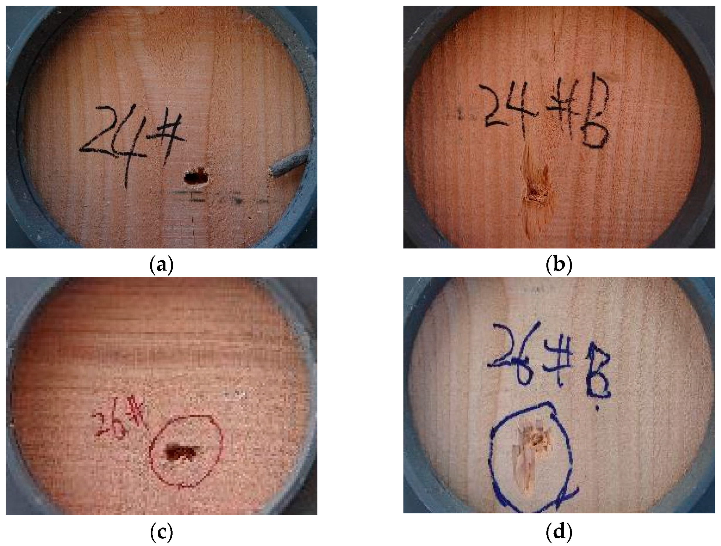
It can be seen from the damaged state of the wood in Figure 3 that the front-end face of the wood leaves a hole with a diameter similar to the fragment after penetration, and there is no obvious damage expansion effect around the hole; The rear-end face is basically the same as the front-end face. Some wood chips are brought out at the mouth, and some wood is peeled off along the axial surface of the wood. It can be seen that when the wood was penetrated by small caliber projectiles, the removal of the penetration trajectory did not damage the additional part of the wood, and the trajectory had no obvious deviation. Therefore, the damage of tungsten alloy spherical fragments to the wood was only a tunnel with a diameter similar to that of the fragments.
Using mat in LS-DYNA MAT_WOOD material parameters, which include parameters of various strength indexes of wood, can also add erosion contact, and can be modified according to different strength indexes in radial and axial directions caused by different wood anisotropy. The material parameters of wood mainly include density, elastic modulus, shear modulus, tensile strength, compressive strength and shear strength, and other parameters are shown in Table 2.
In Table 2, ρ is the density of wood, E// is the parallel modulus of elasticity, E is the vertical modulus of elasticity, σst is the parallel tensile yield stress, σsc// is the parallel compression yield stress, σst is the vertical tensile yield stress, σsc is the vertical compression yield stress, and μ is Poisson’s ratio.
From the photos of the wood target plate, it can be seen that the cutting plane is perpendicular to the radial direction, which is consistent with the state of most fragments in the actual situation. Based on this, a model with the same parameters as the experiment was established in the simulation, and the residual velocity was taken as the main parameter for comparison, as shown in Table 3.
From the comparison of simulation and experimental parameters in Table 3, it can be seen that the material model of wood has a high degree of explanation for residual velocity and failure mode, wherein the maximum error of residual velocity is 22.18% and the minimum error is 0.14%. The failure mode in the simulation is the same as that in the experiment. A little wood flies out on the back of the target plate, as shown in Figure 4.

3. Fragment Penetration Calculation Based on Forest Environment

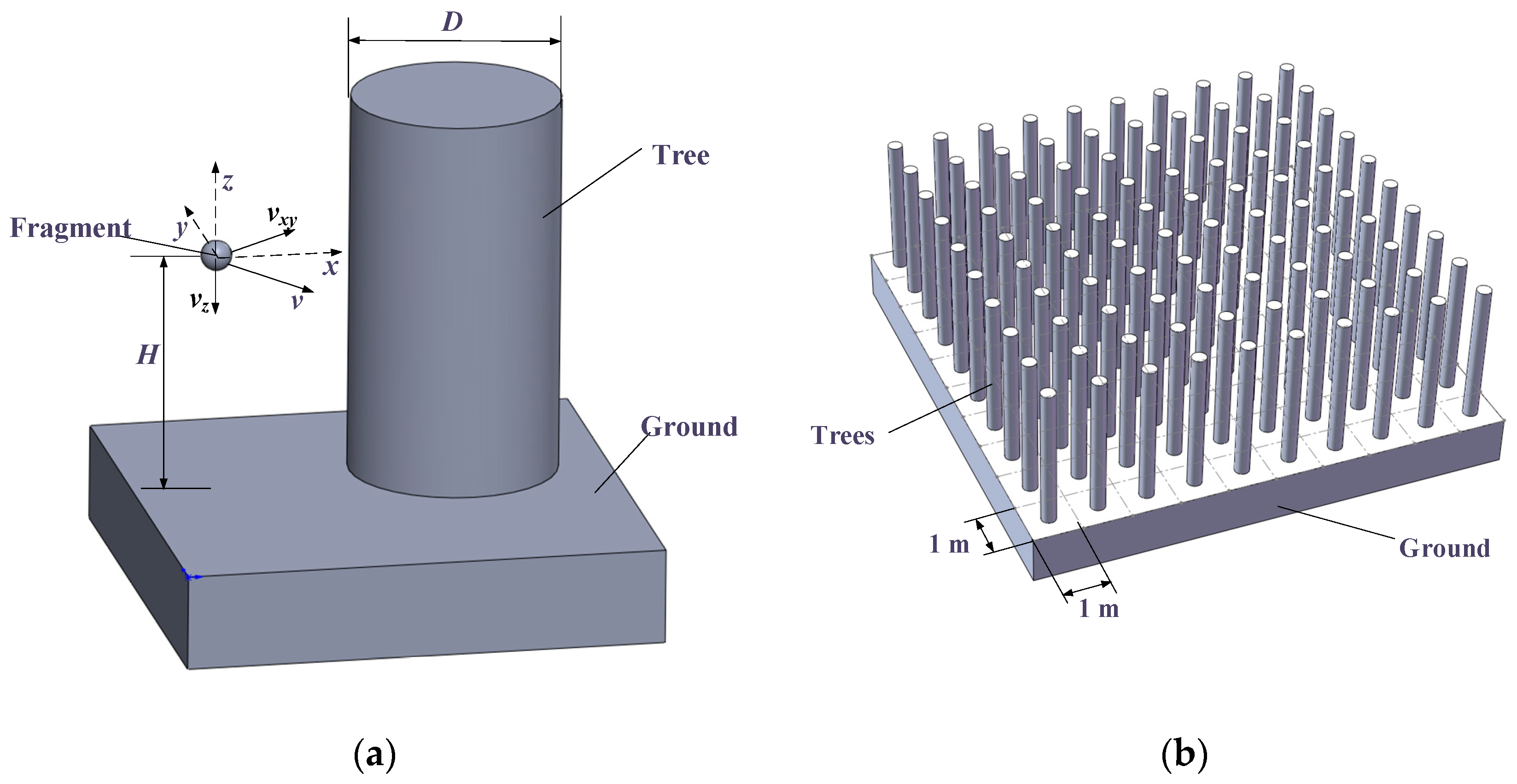
When a warhead is detonated in the forest, various parameters of the warhead and the forest will cause different initial variables of fragment scattering, such as the height H of warhead initiation, the size and direction v of fragment velocity vector, the main wood species caused by forest environment, tree diameter D, and forest density [11] ρ, etc. Among them, due to the difference of tree species, the strength and density of bark and inner core of trees are different, and the thickness of bark is also different [12], so the difference between bark and inner core is ignored in this study. The initial velocity vector of the fragment is decomposed into a vector vxy parallel to the ground and a vector vz perpendicular to the ground, where vxy mainly controls the flight direction of the fragment in the horizontal direction; vz mainly controls the flight time of fragments in the vertical direction. It can be seen that vz and H determine the flight time of fragments in the air, and then affect the flight distance of fragments. See Figure 5 for the fragment penetrating trees and the relationship between the variable parameters of fragments.
In the x-y plane, the fragments may penetrate the wood in the forest in all directions, based on the forest density ρ and tree diameter D. assuming that the trees are evenly distributed in the forest, the number of trees per unit area can be determined according to the stand density (n/m2), so as to determine the land area of each tree. If each tree is placed in the center of its occupied area, the following forest average distribution diagram can be obtained.
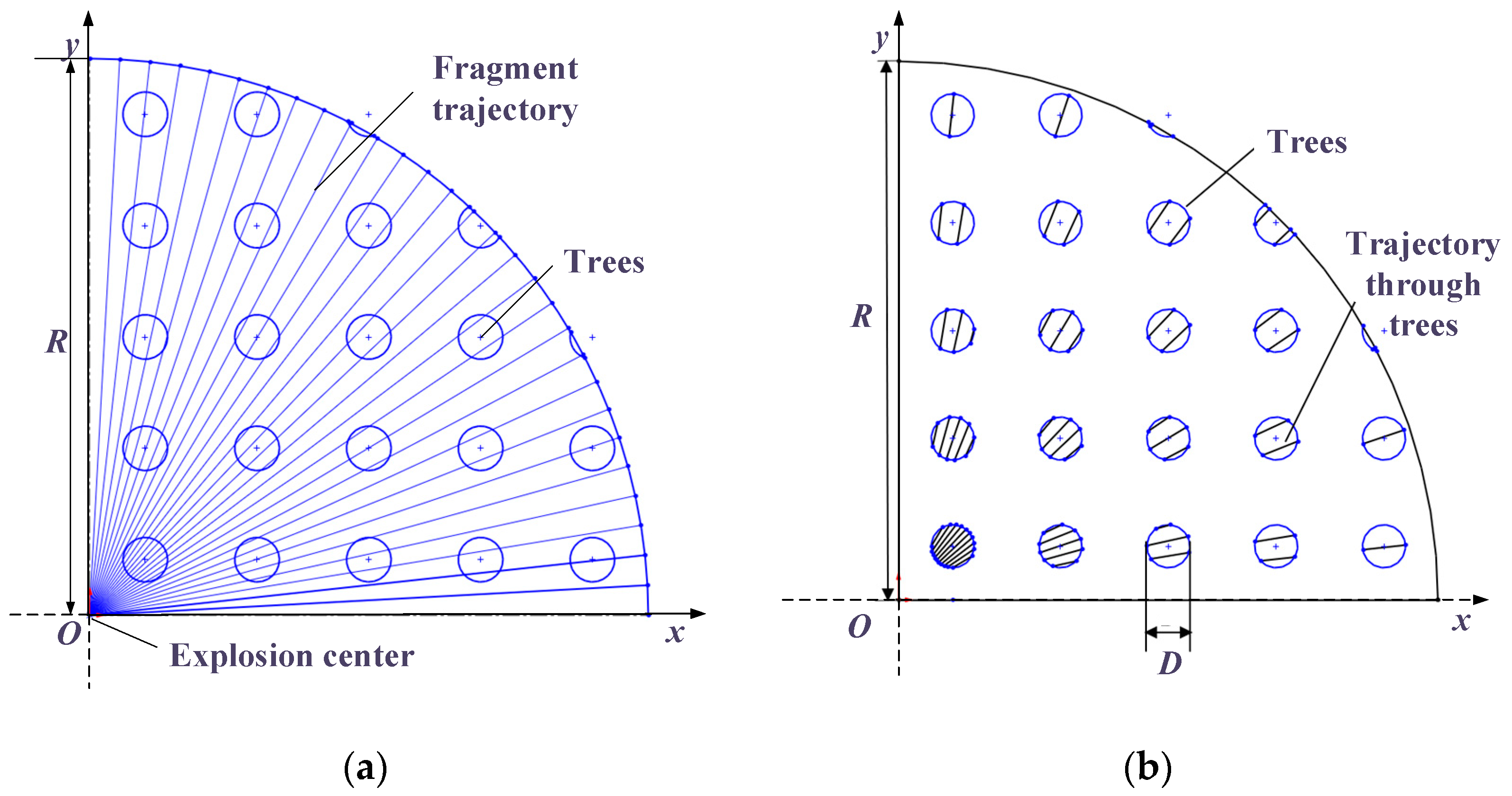
Taking the 1/4 model as an example, the lower left corner is the explosion center, the stand density is 1/m2, and the tree diameter is 300 mm. From the top view, the trajectory of the fragments will fly around without considering the vertical movement time until vxy is 0. By numbering the fragment trajectories at 3° intervals, it can be seen that the lengths of different fragments penetrating the wood in the same radius area are different, some through four trees, and some through only one tree. Although this difference can reflect the maximum damage radius and the minimum damage radius of fragments in the forest environment, individual differences cannot reflect the comprehensive damage degree of all fragments. The trajectory of fragments penetrating trees is shown in Figure 6.
In this paper, a method of average distribution of wood area is adopted. The penetration trajectory area of fragments in the x-y plane is equivalent to the product of fragment diameter d and trajectory length L. The wood area S penetrated in the penetration area can be calculated through the trajectory area it passes through. Ignoring the irregular part of the tree penetration surface, the path length L of the wood medium can be obtained by dividing the penetration area S by fragment diameter d, as shown in formulas (1) to (3).
The calculation formula of the average area of trees is:
S w = ρ D 2 / 4
Among ρ is the density of trees per unit area (n/m2), and D is the average diameter of trees.
The penetration area of the fragment with diameter d on the horizontal plane is:
S p = S w d R
R is the radius length of fragment flight. The average penetration path of fragments is:
L p = S p / R = ρ d D 2 / 4
In the above formula, the following table p represents penetration and w represents wood.
In order to verify the accuracy of the calculation method, the above method is used to verify different parameters in the following three cases:
  • Set the wood diameter and stand density as fixed values, change the horizontal dispersion angle between two adjacent fragments, and compare the average penetration trajectory length of fragments with formula (3). (1°, 3°, 5°)
  • Set different wood diameters without changing the stand density and scattering angle, and compare the average penetration trajectory length of fragments with formula (3). (200 mm, 300 mm, 400 mm)
  • The average penetration trajectory length of fragments is compared with formula (3) by setting different stand densities without changing the tree diameter and scattering angle. (1/m2, 0.5/m2, 0.25/m2)
The comparison results are shown in Table 4.
It can be seen from the error between the actual value and the calculated value corresponding to the three variables of different scatter angles, tree diameters, and stand densities that the calculated value was generally larger than the actual value, and the error rate increased with the increase in the scatter angle. It decreased with the increase in tree diameter, and with the increase in stand density. It can be seen that the accuracy of the simple calculation formula was closely related to the three variables. Therefore, on the one hand, the appropriate range of use of each variable could be obtained to improve the accuracy. On the other hand, the correction coefficient w for the three variables could be added to Equation (3). The dimensionless expression of w is:
w = α D ρ
Using the penetration area of the fragment, the length of the fragment penetrating the wood in the horizontal direction can be obtained, that is, the thickness of the target plate of the fragment penetrating the wood. The overall penetration path Lxyz can be obtained by using the penetration length Lxy of the horizontal plane and the angle β between the fragment velocity vector and the horizontal plane, as shown in formula (5).
L x y z = L p w / cos β
According to the experimental results of 11 mm tungsten alloy fragments and 6 mm fragments, the relationship between the residual velocity and the final velocity is an exponential function when the thickness H of the target plate is constant, which is similar to the velocity attenuation law of the projectile in the air.
Due to the low density and low quality of wood, the velocity attenuation formula of fragments in air is considered first [13]. When fragments fly in the air, they are affected by gravity and air resistance, and gravity makes the flight trajectory of fragments bend. Air resistance causes the attenuation of fragment velocity. Since the distance from the fragment to the target is not too long and the time is very short, the influence of gravity can be ignored, and the fragment trajectory can be approximated as a straight line.
The differential equation of fragment motion is:
m d v d t = 1 2 C D ρ a S v 2
where, CD is the aerodynamic resistance coefficient; ρa is the air density; S is the windward display area of fragments; m v and t are fragment mass, fragment velocity and time respectively. The above formula is transformed into the differential form of velocity v and distance x:
m d v d x = 1 2 ρ a S v
To integrate the above formula, there are:
v 0 v x d v v = C D ρ a S 2 m 0 x d x
So we get:
v x = v 0 e C D ρ a S 2 m x
It can be seen from the above formula that the relationship between vx and v0 should be linear when the thickness x of the target plate and the mass m of the projectile are constant. However, it can be seen from the simulation results that the growth of vx is nonlinear with the increase in v0, as shown in Figure 7. Therefore, the velocity attenuation formula in air cannot be applied to the case of penetrating wood.
According to the hypothesis of Poncelet [14], the equation of penetration depth of a stable moving projectile varying with velocity can be obtained by integration:
m d v d s v = A ( c 1 + c 3 v 2 )
The result is:
s = m 2 c 3 A ln ( c 1 + c 3 v 0 2 c 1 + c 3 v 2 )
where s represents the distance along the straight trajectory. The speed after passing through the obstacle with thickness h is:
v 2 = v 0 2 exp ( 2 c 3 A h m ) + c 1 c 3 exp ( 2 c 3 A h m ) + 1
where v is the residual velocity; v0 is the initial speed; c1 and c3 are constants; A is the cross-sectional area of the projectile; h is the thickness of target plate; and m is the fragment mass. Since the prefabricated fragments are spherical, the above formula can be simplified as:
v 2 = v 0 2 exp ( c 3 h r ρ ) + c 1 c 3 exp ( c 3 h r ρ ) + 1
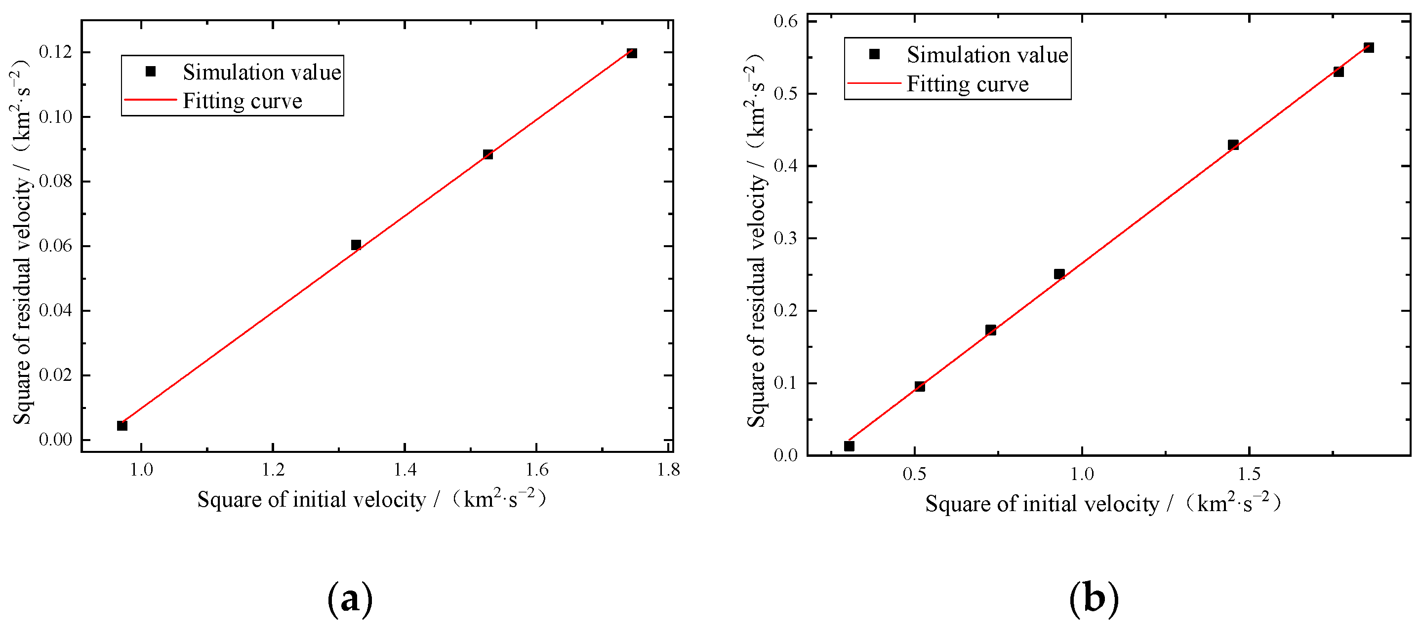
r is the radius of the fragment. According to the Poncelet formula, the difference between the two parameters c1 and c3 obtained from the initial and residual velocity data of 11 mm and 6 mm projectiles is too large, and the difference between c1 and c3 is more obvious. This may be caused by experimental errors, and there is a problem of an insufficient number of samples. Therefore, the simulation values of the two fragments are fitted to obtain the following relationship between v2 and v02, as shown in Figure 8.
From the results of linear fitting, it can be seen that there is an obvious linear relationship between the two, so the c3 value of the two fragments can be calculated. Through comparison, it is found that the difference ratio between the two is not large, so the c3 parameter value of the dried pine wood is 325; However, the c1 value obtained by the Poncelet formula is too different and cannot be regarded as consistent. This should be the result of fragment parameters. Therefore, the fragment radius r in the latter half of the formula is modified and r2.2 is added to the denominator term and substituted into the latter half of the formula. At this time, the c1 value obtained is −2.6. Thus, a modified formula about the residual velocity of wood based on the Poncelet formula is obtained:
v 2 = v 0 2 exp ( 325 h r ρ ) + 2.6 r 2.2 exp ( 325 h r ρ ) + 1
After the residual velocity calculation formula is obtained, the influence of forest on fragment velocity can be obtained according to the scattering radius, stand density, and tree diameter.

4. Simulation Comparison of Different Penetration Modes

Based on the material parameters of wood, this chapter expands and analyzes the influence of the edge effect of wood medium and the number of interval target layers on the residual velocity.

4.1. Edge Effect of Wood Penetration

From the fragment scattering trajectory shown in Figure 6, it can be seen that there are a large number of fragment trajectories passing through the edge of the tree, that is, from the cross-section of the top view, the chord tangent length of the trajectory is very short, and the wood located outside the trajectory is very low in strength, so it is more easily damaged. At this time, it is obviously unscientific to compare the length of the penetration trajectory to the thickness of the target plate [15,16]. Therefore, based on the wood parameter in LS-DYNA, the position of velocity penetration was changed, so as to change the thickness of trees outside the track. The track length in each case was measured and compared with the remaining velocity under the target plate with the same thickness, and the relationship between the outside thickness and the phase difference ratio was observed. See Table 5 for the comparison of the two cases.
Figure 9 is a schematic diagram of the relationship between the difference ratio values of the two cases corresponding to different outer thickness. With the increase in the outer thickness of the trees, the residual velocity of penetrating the trees is always greater than the residual velocity of the normal target plate with the same thickness, and the difference value generally shows a trend that fluctuates upwards. However, it should also be seen that the maximum difference is only 19.2 m/s, so it can be considered that the edge effect has little influence on the high-speed impact fragments.
In conclusion, due to the edge effect of wood penetration, the impact can not be ignored when the outer thickness d is greater than a certain value. Therefore, the penetration trajectory of fragments to trees is still an important basis for the residual velocity of fragments.

4.2. Influence of the Number of Target Layers on the Residual Velocity

Due to the particularity of the forest environment, the penetration factors in the target area are affected by the tree parameters. The most significant of these is the large number of trees on the fragment penetration trajectory caused by the large forest density, which makes the fragments penetrate multi-layer spaced targets. It can be seen from the above inference that the penetration type in the forest environment is generally interval target, and the relationship between the thickness of interval target and the overall target needs to be further calculated [17,18,19,20]. In order to analyze the influence of the number of spaced target layers on the residual velocity under the same target plate thickness, the initial velocity of spherical fragments is set to be 1000 m/s, the fragment diameter is 10 mm, and the total thickness of wood target plates is 500 mm. The target plate layers are divided into six types: 1, 3, 5, 7, 9, and 11. The residual velocity of fragments after penetration is counted separately.
It can be seen from the analysis results in Table 6 that with the increase in the number of target layers, the residual velocity also increases, that is, the number of wood target plates weakens the impact of the thickness of the target plate, and the smaller the thickness of the target plate, the smaller the impact resistance, so that the residual velocity of fragments increases continuously [21,22]. When the number of target plates is 11, the difference ratio reaches 23.89%.

5. Conclusions

Through the penetration test of tungsten alloy spherical fragments into wood targets and the construction of wood parameters in finite element analysis, we achieved a preliminary understanding of the calculation of residual velocity of fragments penetrating wood. By analyzing the relationship between the initial parameters of fragments, residual velocity, stand density and average diameter of trees in the forest, the Poncelet formula was used to obtain the calculation formula of residual velocity, and a calculation model for fragment track length was proposed. The main conclusions of this paper are as follows:
  • Based on the Poncelet formula, it is feasible to calculate the residual velocity of the spherical fragment penetrating the wood target, which is verified by the comparison with the experiment.
  • Based on the forest parameters such as stand density, tree diameter, and fragment flying angle, a simple calculation model of penetration path length is obtained, which has good applicability when the flying angle is small and the stand density is large.
  • The residual velocity increases with the increase in the number of spacer targets on the fragment penetration trajectory, and it changes most obviously when the number of layers is seven. The wood target is less affected by the boundary effect. When the thickness d outside the penetration trajectory decreases continuously, the influence of the wood boundary effect on the residual velocity is relatively stable, and the maximum difference is 2.67%.

Author Contributions

Conceptualization, Z.W. and J.Y. (Jianping Yin); Methodology, Z.W.; Software, Z.W.; Validation, Z.W.; Investigation, Z.W., J.Y. (Jianya Yi), X.L. and J.Y. (Jianping Yin); Experiment, Z.W. and X.L.; Data curation, Z.W. and J.Y. (Jianya Yi); Writing—original draft preparation, Z.W.; Writing—review and editing, J.Y. (Jianping Yin); Supervision, X.L. and J.Y. (Jianping Yin); Project administration, Z.W. All authors have read and agreed to the published version of the manuscript.

Funding

The authors would like to acknowledge the financial support from the 2021 Basic Research Pro-gram of Shanxi Province (Free Exploration), grant number 20210302123207.

Institutional Review Board Statement

Not applicable.

Informed Consent Statement

Not applicable.

Data Availability Statement

The data presented in this study are available on request from the corresponding author. The data are not publicly available due to programming privacy in structural design.

Conflicts of Interest

The authors declare no conflict of interest.

References

  1. Xu, Y.X.; Han, X.G.; Zhao, X.X.; Wang, S.S. Experimentation Research on Failure Behavior of Tungsten Alloy Penetrating Low Carbon Steel Plate at High Velocity. Rare Met. Mater. Eng. 2016, 45, 122–126. [Google Scholar]
  2. Guo, W.Q.; Liu, J.X.; Xiao, Y.; Li, S.K.; Zhao, Z.Y.; Cao, J. Comparison of penetration performance and penetration mechanism of w-cu shaped charge liner against three kinds of target: Pure copper, carbon steel and Ti-6Al-4V alloy. Int. J. Refract. Met. Hard Mater. 2016, 60, 147–153. [Google Scholar] [CrossRef] [Green Version]
  3. Fu, H.; Gao, S.Q.; Jin, L.; Wu, Q.H. Research on the acceleration phenomenon of projectile leaving the target when penetrating thick concrete target. Int. J. Impact Eng. 2022, 164, 104191. [Google Scholar] [CrossRef]
  4. Dong, Y.X.; Feng, S.S.; Huang, G.Y.; Liu, C.M.; Xiao, L.X.; Song, Q. Ballistic Impact Characteristics of Flat-nose Projectile Penetrating Concrete and Soil Compound Target. Int. J. Nonlinear Sci. Numer. Simul. 2012, 13, 255–260. [Google Scholar] [CrossRef]
  5. Naghizadeh, Z.; Pol, M.H.; Alawode, A.O.; Faezipour, M.; Liaghat, G.H.; Via, B.K.; Abdolkhani, A. Performance Comparison of Wood, Plywood, and Oriented Strand Board under High- and Low-Velocity Impact Loadings. For. Prod. J. 2021, 71, 362–370. [Google Scholar] [CrossRef]
  6. Wang, H.X.; Ramakrishnan, K.R.; Shankar, K. Experimental study of the medium velocity impact response of sandwich panels with different cores. Mater. Des. 2016, 99, 68–82. [Google Scholar] [CrossRef]
  7. Haro, E.E.; Szpunar, J.A.; Odeshi, A.G. Dynamic and ballistic impact behavior of biocomposite armors made of HDPE reinforced with chonta palm wood (Bactris gasipaes). Def. Technol. 2019, 14, 238–249. [Google Scholar] [CrossRef]
  8. Basha, M.; Wagih, A.; Melaibari, A.; Lubineau, G.; Abdraboh, A.M.; Eltaher, M.A. Impact and post-impact response of lightweight CFRP/wood sandwich composites. Compos. Struct. 2021, 279. [Google Scholar] [CrossRef]
  9. Kerkhoff, W.; Alberink, I.; Mattijssen, E.J.A.T. An Empirical Study on the Relation Between the Critical Angle for Bullet Ricochet and the Properties of Wood. J. Forensic Sci. 2015, 60, 605–610. [Google Scholar] [CrossRef] [PubMed]
  10. Xia, Z. Numerical Simulation and Experimental Analysis of Cutting Soil and Wood Based on ANSYS/LS-DYNA; Beijing Forestry University: Beijing, China, 2016; pp. 40–45. [Google Scholar]
  11. Zhang, L.J.; Hui, G.Y.; Sun, C.Z. Comparison of different stand density measures. J. Fujian For. Univ. 2011, 31, 257–261. [Google Scholar]
  12. Tan, L.; Liu, Y.; Wei, G.Y. Study on the Bark Basic Density and the Timber Basic Density of Acacia mangium and Acacia crassicarpa. Anhui Agric. Sci. 2013, 41, 2993–2994. [Google Scholar]
  13. Wang, S.S. Endpoint Effect; Science Press: Beijing, China, 2019; pp. 182–208. [Google Scholar]
  14. Backman, M.E. Terminal Ballistics; National Defense Industry Press: Beijing, China, 1981; pp. 49–53. [Google Scholar]
  15. Zhang, X.L.; Wang, H.; Tan, Z.J. Relevance Between Aspect Ratio of Projectile and Boundary Effect of Concrete Target. J. Weapon Equip. Eng. 2018, 39, 11–13. [Google Scholar]
  16. Minak, G.; Ghelli, D. Influence of diameter and boundary conditions on low velocity impact response of CFRP circular laminated plates. Compos. Part B-Eng. 2008, 39, 962–972. [Google Scholar] [CrossRef]
  17. Yuan, Y.N.; Hu, J.; Wang, S.L. Numerical Simulation and Experimental Investigation on Slanting Penetration of Tungsten Alloy Long Rod upon Three-ply Me. J. Sichuan Mil. Eng. 2011, 32, 10–15. [Google Scholar]
  18. Wu, X.M.; Zhai, X.L.; Jiang, H.Z. An investigation on the penetration of multi-layered space plates of aluminum alloy by a tungsten sphere. J. Beijing Univ. Technol. 1997, 1, 115–120. [Google Scholar]
  19. Sun, T.; Feng, S.S.; Pei, S.X. The study of penetration of tungsten spheres at ly12cz spaced layered targets. Acta Armamentarii. 1998, 2, 108–112. [Google Scholar]
  20. Bi, G.J.; Yin, J.P.; Wang, Z.J.; Jia, Z.J. Micro Fracture Behavior of Composite Honeycomb Sandwich Structure. Materials 2021, 14, 135. [Google Scholar] [CrossRef] [PubMed]
  21. Tang, X.Z.; Wang, Z.J.; Dong, L.Y.; Dong, F.D. Numerical Simulation Analysis of Projectile Oblique Impact Target Plate. J. Ordnance Equip. Eng. 2019, 40, 47–50. [Google Scholar]
  22. Zhou, X.; Long, Y.; Yue, X.B. Effects of the yaw on kinetic projectile penetrating into spaced targets in high impact. J. Ballist. 2004, 4, 7–11. [Google Scholar]
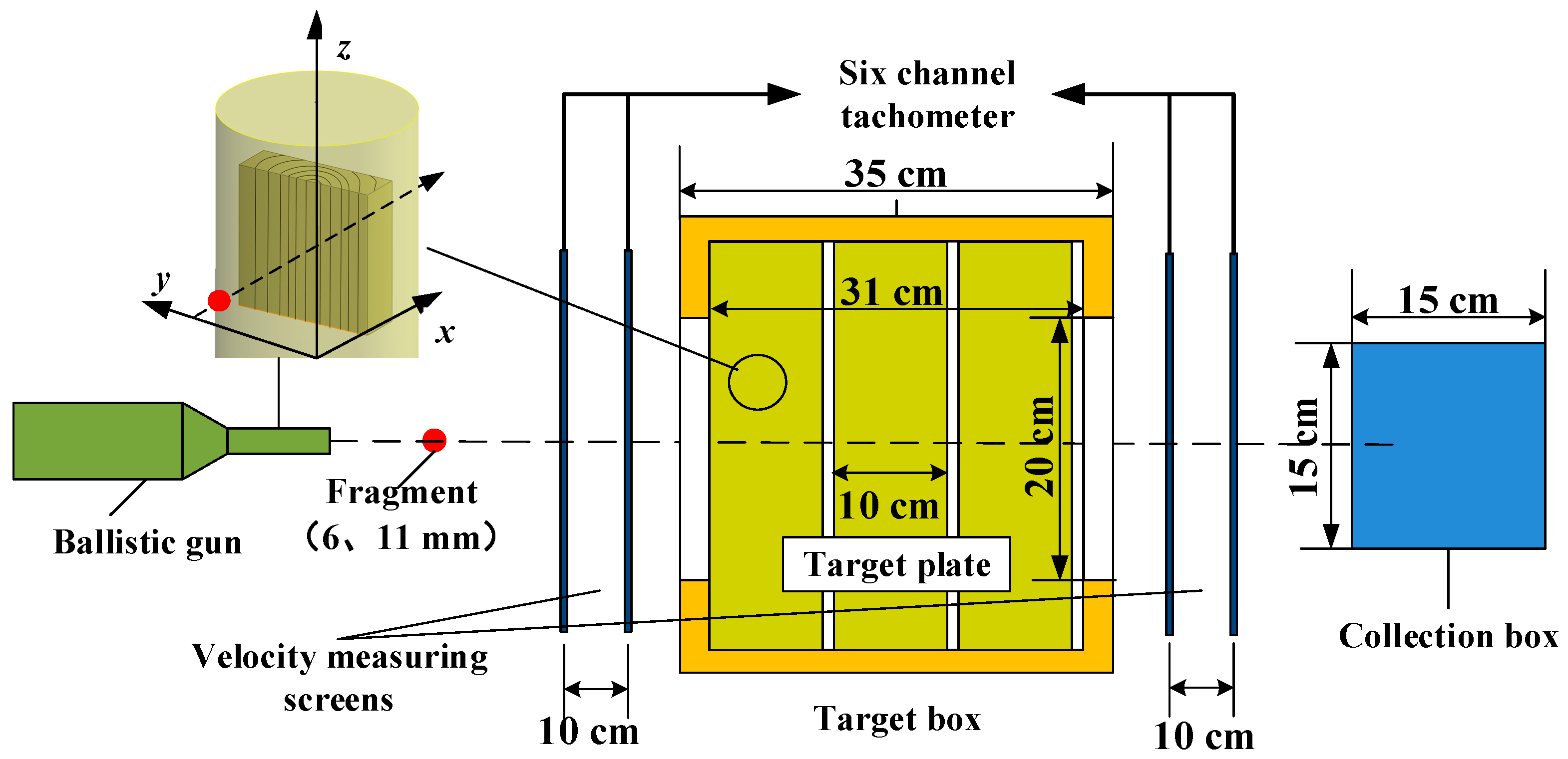
Figure 1. Schematic diagram of penetration test scheme.
Applsci 12 11333 g001
Figure 2. Physical diagram of test device. (a) is experimental cartridge (sabot, fragment); (b) is the experimental station.
Applsci 12 11333 g002
Figure 3. Failure of wood target at two speeds. (a) is 965 m/s frontal failure; (b) is 965 m/s back failure; (c) is 1363 m/s frontal failure; (d) is 1363 m/s back failure.
Applsci 12 11333 g003
Figure 4. Comparison of experiment and simulation on the back of target plate. (a) is experiment; (b) is numerical simulation.
Applsci 12 11333 g004
Figure 5. Model of fragment penetrating trees in forest. (a) This is a schematic diagram of fragments penetrating trees; (b) This is an assumption of average distribution of trees (1/m2).
Applsci 12 11333 g005
Figure 6. A model for the uniform dispersion of fragments in forests.(1/4 model) (a) is schematic diagram of evenly scattered fragments; (b) is penetration trajectory through trees.
Applsci 12 11333 g006
Figure 7. Relationship curve between v0 and vx obtained by fitting. (a) is 6 mm fragment; (b) is 11 mm fragment.
Applsci 12 11333 g007
Figure 8. Relationship curve between v02 and vx2 obtained by fitting. (a) is 6 mm fragment; (b) is 11 mm fragment.
Applsci 12 11333 g008
Figure 9. Influence of edge effect on residual velocity. (a) is comparison between residual velocity considering edge effect and plane target; (b) is residual speed difference and difference ratio under two conditions.
Applsci 12 11333 g009
Table 1. Test conditions.
NumberFragment Type/mmTarget Plate TypeInitial Speed/(m·s−1)Residual Speed/(m·s−1)
16pine985.65115.36
26pine1151.6153.24
36 pine854.05no penetration
46 pine1321.07347.36
56 pine1235.48172.36
66 pine785.44no penetration
76 pine663.28no penetration
86 pine589.55no penetration
911 pine1205.19654.09
1011 pine853.13426.81
1111 pine965.77539.42
1211 pine1363.24708.13
1311 pine551.4870.84
1411 pine717.86306.18
1511pine435.76no penetration
1611pine1329.6598.68
Table 2. Wood material parameters.
ρ/(g·cm−3)E///GPaE/GPaσst///GPaσsc///GPaσst/GPaσsc/GPaμ
0.47311.350.24680.08520.02120.002050.004080.157
Table 3. Comparison of residual velocities of 6 mm and 11 mm fragments.
NumberFragment Diameter/mmInitial Speed/(m·s−1)Experimental Residual Speed/(m·s−1)Simulation Residual Speed/(m·s−1)Difference Ratio/%
16985.6585.3666.4322.18
261151.6223.24245.710.06
36854.05no penetrationno penetrationnothing
461321.07347.36346.00.39
561235.48272.36297.39.16
66785.44no penetrationno penetrationnothing
76663.28no penetrationno penetrationnothing
86589.55no penetrationno penetrationnothing
9111205.19654.09655.00.14
1011853.13426.81416.32.46
1111965.77539.42500.97.14
12111363.24708.13750.76.01
1311551.4895.84114.419.37
1411717.86306.18308.80.86
1511435.76no penetrationno penetrationnothing
16111329.6598.68728.121.62
Table 4. Comparison between model calculation value and formula calculation value under different conditions.
NumberStand Density
ρ/(n·m−2)
Tree Diameter D/mmScattering Angle αModel Calculation Value/mmFormula Calculation Value/mmError Rate/%
113001336.78353.44.93
213003335.82353.45.23
313005270.10353.430.84
412003138.85157.0813.13
513003335.82353.45.23
614003596.26628.35.37
713003335.82353.45.23
80.53003165.76176.76.60
90.25300366.0588.433.84
Table 5. Residual velocity considering edge effect and residual velocity of normal target plate.
NumberThickness/mmEdge Effect/(m·s−1)Normal Target Plate/(m·s−1)
10467.2464.0
25473.3464.3
315476.7467.8
425481.4470.4
535486.6473.6
645488.9480.4
755508.7495.3
865517.6508.3
975528.3524.5
1085556.3543.2
1195579.7563.4
12105598.3597.1
13115643.1629.0
14125686.8672.3
15135745.0738.5
16145857.5838.3
Table 6. Effect of the number of spacer layers on the residual speed.
NumberFragment Diameter/mmNumber of Spacer LayersSimulation Residual Speed/(m·s−1)Difference Ratio/%(Compared with 1)
1101112.60
2103109.5−2.75
3105110.7−1.69
4107124.010.12
5109129.214.74
61011139.523.89
Publisher’s Note: MDPI stays neutral with regard to jurisdictional claims in published maps and institutional affiliations.