Article

A Novel Fluorescent-Material-Based Simple Method for Sunscreen Evaluation

1
Department of Precision Machinery Engineering, College of Science and Technology, Nihon University, 7-24-1 Narashinodai, Funabashi-shi, Chiba 274-8501, Japan
2
Department of Mechanical Engineering, College of Engineering, Shibaura Institute of Technology, 3-7-5 Toyosu, Koto-ku, Tokyo 135-8548, Japan
*
Author to whom correspondence should be addressed.
Appl. Sci. 2022, 12(22), 11521; https://doi.org/10.3390/app122211521
Submission received: 15 September 2022 / Revised: 1 November 2022 / Accepted: 9 November 2022 / Published: 13 November 2022
(This article belongs to the Section Optics and Lasers)

Abstract

:
ISO standards exist for evaluating sunscreens, such as those based on visual inspection. This assessment yields subjective results and is thus unreliable. Therefore, to verify the results of the visual assessment of sunscreens, quantitative evaluation methods are necessary. These methods require the measurement of the total radiation energy that is diffusely transmitted in all directions. For the measurements, although an integrating sphere is widely used to measure diffusely transmitted radiation, a simpler measurement would contribute to the easy usage of quantitative and objective evaluation. We propose the use of fluorescent materials as an alternative method to characterize sunscreens. In this method, a layer containing a fluorescent material is placed behind the sunscreen, and when the excitation radiation transmitted through the sunscreen reaches the fluorescent layer, it emits fluorescence. The feasibility of this measurement method was evaluated through numerical analysis and it demonstrated that hemispheric transmittance can be measured when the fluorescent layer is of high concentration or thick. Additionally, a prototype fluorescent layer was fabricated, and also the results were compared with the amount of diffusely transmitted UV from several commercial sunscreens. This pilot evaluation measurement method showed that the UV shielding index shown on the package does not necessarily truly reflect the amount of UV energy transmitted through the sunscreen, thus failing to provide the expected protection.

1. Introduction

Recently, the harmful effects of UV rays on human skin have attracted increasing attention. To protect the skin from these harmful effects, sunscreens have been developed, and the performance of sunscreens is expressed by two values: SPF and PA. SPF stands for the sun protection factor, and the higher its value, the better the performance in shielding ultraviolet B (UVB) radiation in the wavelength range of 290–320 nm. PA stands for the protection grade of UVA, and this index is used in Japan and Korea. UVA is ultraviolet A, in the wavelength range of 320–400 nm. The UVA protection factor (UVAPF) has been used in Europe since 2013. The higher the level of PA or UVAPF, the better the shielding performance against UVA [1,2].
For many years, SPF and PA (UVAPF) values have been measured according to regulations set by the Comité de Liaison des Industries de la Parfumerie (COLIPA) in Europe and by the Food and Drug Administration (FDA) in the United States [3,4,5]. Additionally, ISO 24444 and ISO 24442 were published in 2010 and 2011 [6,7], respectively. These standards regulate the evaluation method for sunscreens and unify the index of shielding effectiveness against UVA to UVAPF. Before ISO 24444 and 24442, sunscreens were evaluated not only by visual changes in skin color caused by UV rays irradiated from a predetermined light source, but also by hemispherical transmittance measurement [8]. The existing COLIPA and FDA standards do not specify a method for determining UVAPF values but stipulate that SPF values are determined by hemispherical transmittance measurement of sunscreens using an integrating sphere. Alternatively, the ISO standard specifies that both SPF and UVAPF values should be determined through visual evaluation. However, the visual observation evaluation method may yield different results depending on the nature of the subject’s skin, differences in health status, and the evaluator’s skill. Therefore, it is necessary to conduct a quantitative evaluation by measuring the hemispherical transmittance of the sunscreens.
When measuring the hemispherical transmittance of sunscreens, the integrating sphere has long been used as a basic tool [9], and research has continued to not only expand the range of types of measurement objects and wavelengths [10,11,12,13,14,15,16] but also to improve the accuracy of measurement [17,18,19,20,21,22,23] with the details of a few studies described as follows. Pickering et al. [11] studied a system to simultaneously measure the scattering coefficient, absorption coefficient, and anisotropy factor to determine the optical properties of biological tissue. In this study, a measurement system with a scattering sample placed between two integrating spheres was constructed to measure the scattering parameters experimentally and evaluate them theoretically. Gaigalas et al. [15] proposed a method to measure the fluorescence quantum yield using a commercial spectrophotometer with a 150 mm integrating sphere detector. They obtained the fluorescence quantum yield from a combination of absorbance measurements of the buffer and analyte solution inside and outside the integrating sphere. Bergmann et al. [19] developed a spectroreflectometer/transmissometer that can determine absolute optical characteristics in the wavelength range of 300–2600 nm by using three rapidly interchangeable 20 cm integrating spheres. They showed that these values can be measured with extremely high accuracy. Zerlaut et al. [23] developed an accurate method to determine the optical properties of scattering media using an integrating sphere-based setup based on theoretical investigations of the light propagation within an integrating sphere. They tested their experimental system or model with Monte Carlo simulations and in practice using an integrating sphere made by a 3D printer. Then, they determined the effective scattering coefficient and the absorption coefficient in the wavelength range of 400–1500 nm.
These examples show that integrating spheres are generally used to measure the hemispherical reflectance and transmittance of scattering and absorbing media. However, there is a disadvantage in that the integrating sphere is a highly specialized instrument and cannot be used easily. Thus, this study proposes a measurement system specialized for measuring radiation scattering/absorbing media, particularly diffused transmitted radiation, without the use of an integrating sphere.
First, the procedure for calculating the hemispherical transmittance from the experimental data and an overview of the measurement apparatus are presented. Next, verifications are performed both experimentally and analytically. Finally, the method is tested by measuring the amount of UV radiation transmitted from the sunscreens.

2. Concept of Proposed Measurement Method

Generally, hemispherical transmittance is used as an indicator of radiation [24].
T = q t / q i n
where qin and qt are the incident and transmitted flux, respectively. In a conventional measurement system, as shown in Figure 1, to obtain the incident radiation flux, the incident radiation is first made to enter directly into the integrating sphere, and then a portion of the emitted radiation is measured. Next, to obtain the transmitted flux through the sunscreen sample, the incident radiation through the sample is made to enter the integrating sphere, and a portion of the emitted radiation is measured in the same manner that the incident flux was obtained. Because the measured values obtained by the photodetector are proportional to the amount of radiative energy detected, E(AS), they are expressed by Equation (2) using the radiative intensity I(θ, φ) emitted from the integrating sphere. Here, A and S represent the apertures of the integrating sphere and photodetector, respectively.
E ( A S ) = I ( θ , φ ) cos θ Δ S L 2 Δ A
where ΔΩ is the area of the integrating sphere aperture, ΔS is the area of the photodetector, L is the distance between the integrating sphere aperture and photodetector, and θ and φ are the polar angle and azimuthal angle from the integrating sphere aperture to the photodetector, respectively. In most integrating-sphere measurement systems, although a photodetector is installed directly at the aperture of the integrating sphere (Figure 1), the integrating-sphere aperture and photodetector are shown separately to correspond to the system proposed in this study. Generally, θ, φ, ΔS, L, and ΔA are constants in the experimental apparatus because the positional relationship between the aperture of the integrating sphere and detector is fixed. Therefore, the measured value obtained by the detector is proportional to the radiative intensity I. Because the radiation is not directional, the relationship between the emitted flux from the integrating sphere q and intensity I is given by Equation (3).
q = 2 π π / 2 I cos θ · sin θ d θ d φ = π   I
If the radiation escaping from the aperture is negligible, the amounts of radiation entering the integrating sphere and being emitted are equal. Therefore, in a measurement system using an integrating sphere, the hemispherical transmittance T can be obtained using Equation (4):
T = E t / E i n
where Ein is the measured value of the radiation passing through the integrating sphere without a sample and Et is the measured value of the radiation through the sample and integrating sphere. Because the measured values are proportional to the amount of detected radiation energy, they are represented by the symbol E. Thus, to measure the hemispherical transmission, the radiation has to diffuse in order to be detected by the photodetector and thus would require a diffuser.
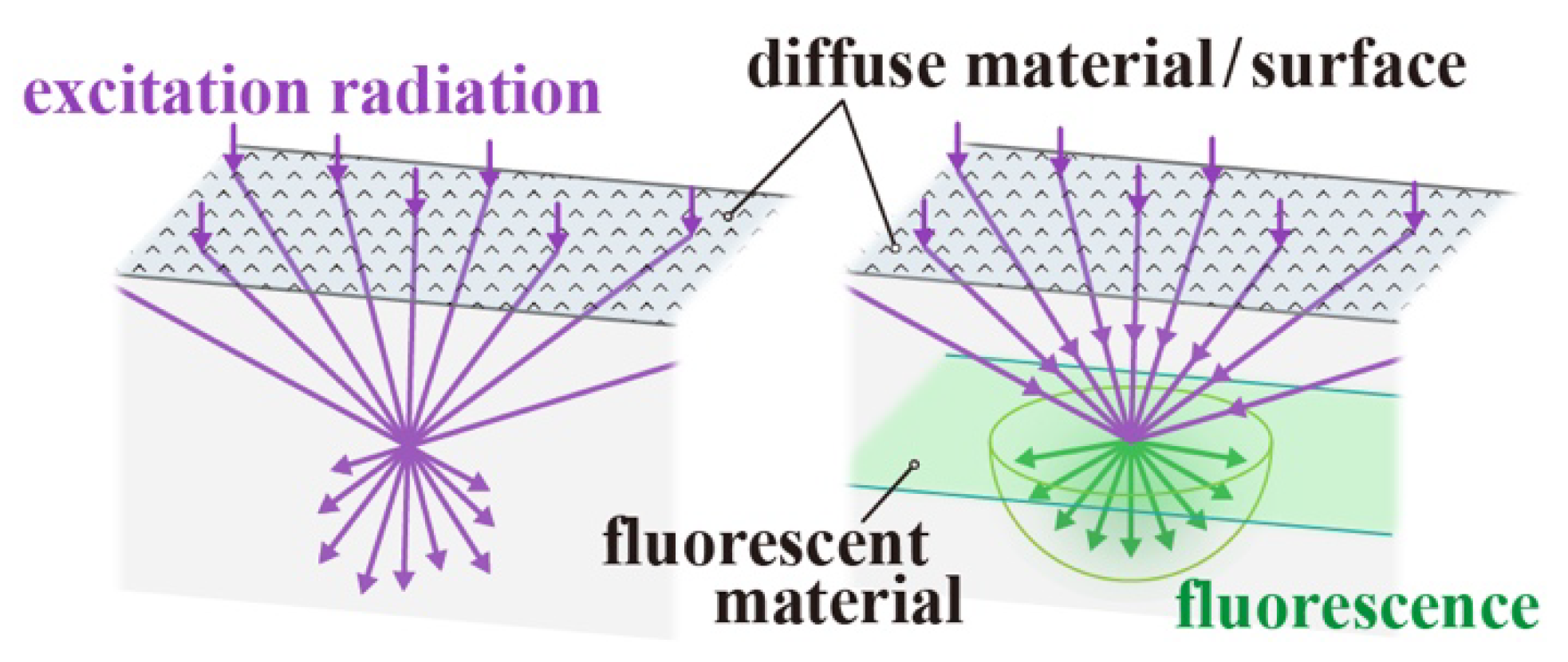
This study proposes a layer that includes a fluorescent material placed behind the sample, as shown in Figure 2. The radiation transmitted through the sample penetrated the fluorescent layer, which in turn emitted fluorescence. The emitted fluorescent radiation is proportional to the excitation radiation incident on the material and is always isotropic. Therefore, having a fiber to detect the emitted fluorescence would make it possible to measure the hemispherical transmittance from Equations (1) to (4).
As shown in Figure 3, the hemispherical transmittance T is calculated from Equation (5) using the fluorescent radiation measured when the excitation radiation is incident on a smooth glass slide at an incidence angle θin with reflectance R(θin) obtained from Fresnel’s law.
T = q s q i n = q f · s q f · i n / { 1 R ( θ i n ) } = E f · s E f · i n { 1 R ( θ i n ) }
where qf·in refers to the fluorescence flux generated by the excitation radiation incident on a smooth glass slide, and qf·s is the fluorescence flux generated by the excitation radiation transmitted through the sample placed on the glass slide surface.
Hernández-Rivera et al. [25] also proposed a study using fluorescent films to examine the effectiveness of sunscreens. Although the concept is the same, our study details a procedure to calculate the hemispheric transmittance, an engineering index that can be applied to fields other than cosmetics from the measured data.

3. Measurement System

Figure 4a shows a detailed view of the region, where the incident excitation radiation was converted to fluorescence. The fluorescent layer was prepared by mixing powdered fluorescent material UV-G (TERRENAVI Co., Tokyo, Japan) and transparent UV-curable resin HI-LOCK UV-591 (Toho-Kasei Co., Tokyo, Japan). This fluorescent material emits green fluorescence (517 nm) by absorbing UV rays as the excitation radiation with a recommended wavelength in the range of 200–365 nm (Figure S1). Although UV-G was used as a target to evaluate the sunscreen agents in this study, it is also possible to measure the hemispherical transmittance at other wavelengths by selecting a fluorescent material that matches the measurement target.
The viscosity of HI-LOCK UV-591 was reduced by heating it to approximately 70 °C in a hot water bath so that UV-G could be sufficiently dispersed while stirring, suppressing the inclusion of air bubbles. The mixture of resin and fluorescent material was sandwiched between two glass slides and cured or, in other words, the mixture was hardened by exposure to UV light. The curing process fixes the fluorescent material within the resin. Consequently, the fluorescent material remains uniformly dispersed, ensuring the generation of uniform fluorescence irrespective of the direction of the excitation radiation.
Figure 4b shows the overall experimental configuration for measuring the fluorescent radiation. A semiconductor laser emitting UV rays (375 nm, TC20-3720-15, NEOARK Corporation, Tokyo, Japan) was used as the light source. The laser beam was expanded by a beam expander so that the beam had a uniform intensity. An aperture of 10 mm diameter was used to create uniform illumination on the sample surface. Thus, as there is also a zero gap between the sample and the fluorescent material, we can say approximately that the size of the beam incident on the sample surface with a fluorescent layer was 10 mm. This beam, 10 mm in diameter, was incident on the sample surface with a fluorescent layer. The diffuse material as the sample should be applied to a uniform thickness on the surface of the glass slide as shown in Figure 4a. While UV radiation passed through the fluorescent layer, we detected the emitted fluorescent radiation through a sharp cut filter (SCF-50S-42L, Sigmakoki Co., Ltd., Tokyo, Japan) and an optical fiber probe with a receiving lens with a narrow view angle (0.6 × 10⁻³ sr) (fiber collimator, C-OPCL05G-001/101-L=2, Nippon Sheet Glass Co., Ltd., Tokyo, Japan). The view area on the glass slide surface was approximately 2 mm in diameter. The sharp cut filter was used to remove the excitation radiation transmitted through the fluorescent layer. The light collected by the optical fiber probe was detected by a photomultiplier tube (R374, Hamamatsu Photonics, Shizuoka, Japan) at a specific frequency of a light chopper placed in front of the laser source. A lock-in amplifier (LI5640, NF Corporation, Kanagawa, Japan) was used to selectively measure the signal that varied at the chopper frequency, rejecting the detected signal at other frequencies, and thus removing noise. The output value of the lock-in amplifier yields the hemispherical transmittance obtained using Equation (5).
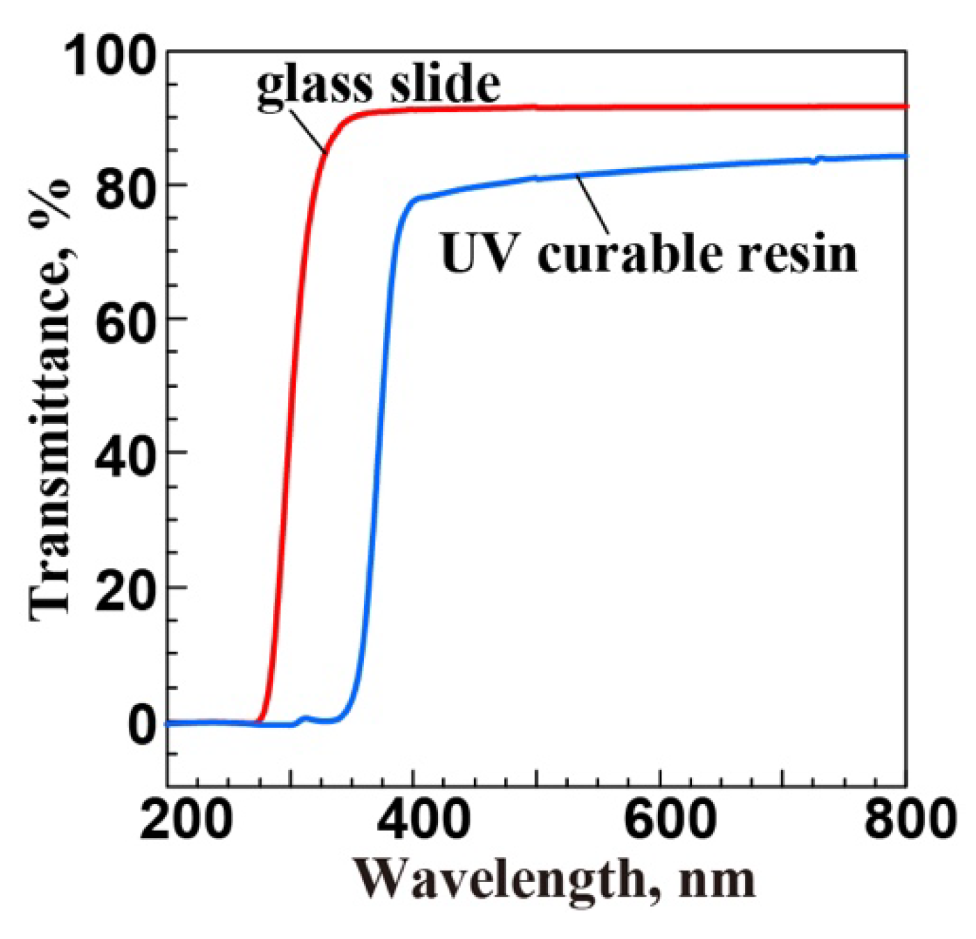
The glass slides used in this study were 1 mm thick soda-lime glass slides. Generally, soda-lime glass does not have high transmittance for radiation that has wavelengths in the range of 400 nm or less. Figure 5 shows the spectral transmittance of the glass slides used in this study and that of the UV-curable resin. For the UV-curable resin, the transmittance dropped sharply for radiation wavelengths below 400 nm and was approximately 50% at 375 nm. In contrast, the transmittance of the resin was more than 80% at approximately 517 nm, the wavelength of fluorescence, and was sufficiently detectable by our system. Because the transmittance of the glass slide used in the experiments was more than 90% for radiation with a wavelength of 375 nm, it is expected to decrease the amount of fluorescent radiation and thus will put a limit on the detectable limits.
However, such effects could be considerably reduced by slide glasses made of quartz which has much higher transmittance over a wider range of UV wavelengths. For example, the report on the effectiveness of different substrate materials for in vitro sunscreen tests mentioned that the application of sunscreen products on roughened quartz plates was performed efficiently [26]. As the main focus of this study is the demonstration of the technique itself, we would like to point out that even having a glass slide makes the measurement possible as shown later.

4. Validation of Proposed Method

4.1. Validation Procedures

While the amount of fluorescence emission is proportional to the amount of absorbed UV energy, the amount of absorbed UV energy depends on the distance or thickness that the UV radiation travels through the fluorescent layer. To include the physical distance and characteristics of the material, a dimensionless parameter called the distance index or thickness index τ was introduced, which is the product of the extinction coefficient β and the physical distance of radiation traveling through the fluorescent layer x, as shown in Equation (6). The units of β and x are mm−1 and mm, respectively:
τ = 0 x β   d x
The distance of the UV radiation traveling through the fluorescent layer is determined by the incident angle of the UV radiation. Thus, the measured fluorescence intensity could differ depending on the incident angle of the UV radiation, even at the same incident energy. For this method to be effective, irrespective of the incident angle, when the amount of energy incident on the fluorescent layer is the same, the same fluorescence intensity must be measured.
In practical applications, UV radiation is incident on the fluorescent layer in various directions because it is transmitted through scattering materials, such as sunscreen. Therefore, the validity of this system was evaluated by both numerical analysis and experimental measurement of the amount of fluorescence generated when the UV radiative energy Eet was incident on a fluorescent layer with a thickness index τf at different incident angles.

4.2. Experiments

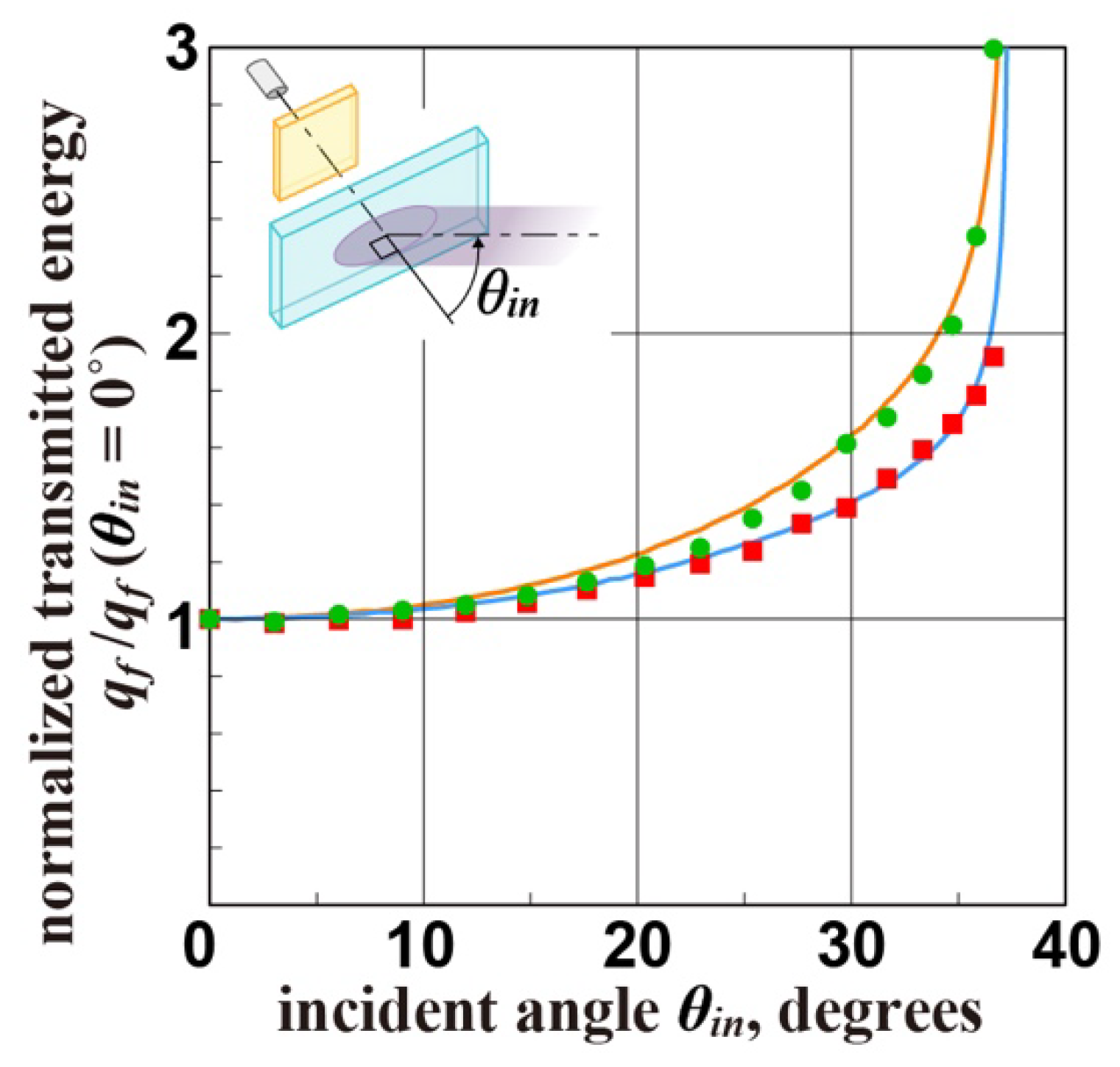
The fluorescence intensity was measured when the UV radiation was incident on the fluorescent layer at different incident angles. Fluorescent layers with two different mass concentrations of 33 wt% and 20 wt% of fluorescent materials with the same thickness of 1 mm were prepared for the preliminary experiment. These two fluorescent layers were examined to determine whether the generated fluorescence intensity was constant regardless of the incident angle of the excitation UV radiation. The UV excitation energy was kept constant. Because the physical properties of the fluorescent layer for UV radiation are unknown, the radiative properties of the prototype fluorescent layers were estimated by comparing the experimental and analytically calculated results.

4.3. Numerical Analysis

Although the analytical model established in this study is not necessarily precise, it can verify the feasibility of the developed method and clarify the feasible conditions. The numerical model is composed of a fluorescent layer of a continuous medium with a thickness index of τf; the radiation is scattered and/or absorbed in this medium. The refractive index of the fluorescent layer is assumed to be 1.65, which is the same as that of the UV-curable resin used. At the interface between the layer and air (n = 1.0), differences in the indices generate Fresnel reflections at the surface. Although the actual fluorescent layer is sandwiched between glass slides, the effect of the glass slides can be omitted because they have almost the same refractive index as the resin. Propagations of UV radiation and fluorescence within the layer are described by radiation transfer Equations (7) and (8), respectively [27] (Figure S2):
d I e ( τ , Ω ) d τ = I e ( τ , Ω ) + ω e 4 π 4 π I e ( τ , Ω ) Φ ( Ω Ω ) d Ω ( 1 ω e )   Q · I f ( τ , Ω )
d I f ( τ , Ω ) d τ = I f ( τ , Ω ) + ω f 4 π 4 π I f ( τ , Ω ) Φ ( Ω Ω ) d Ω
where Ω is a unit vector representing the propagation direction of the radiation, and τ is the coordinate along the direction of the distance index. Ie is the intensity of the UV radiation propagating within the layer. If is the intensity of the fluorescent radiation in the Ω direction that is produced by absorbing excitation radiation when Ie passes the microvolume at position τ in the Ω direction, and ω is the albedo, which is defined as follows. The radiation intensity decreases as the radiation passes through the scattering/absorbing medium according to the extinction coefficient β, which can be expressed by Equation (8), where σ is the scattering coefficient and α is the absorption coefficient. The albedo ω is defined by Equation (9):
β = σ + α
ω = σ β
In other words, the albedo ω, is the fraction of the amount of scattered radiation out of the absorbed excitation radiation as it propagates within the medium. ωe is the albedo of the excitation radiation, whereas ωf is that of the fluorescent radiation. Fluorescent materials absorb only the UV radiation; the generated fluorescence is not absorbed but scattered. Therefore, the albedo of the fluorescent layer was assumed to be ωf = 1.
Q is the fluorescence yield, which describes the probability of the material emitting fluorescence when an activated atom returns to the ground state. Although the actual fluorescence yield Q of this fluorescent material is unclear, the ratio of the measured fluorescence intensity is not affected by the value of Q. Therefore, the analysis was performed as Q = 1. Generally, fluorescence is assumed to be emitted isotropically. When UV radiation and fluorescence are scattered in the fluorescent layer, they are assumed to be anisotropic scattering and follow the Henyey–Greenstein function Φ(Ω′→Ω). The scattering phase function depends on the wavelength of the radiation. However, the difference in the scattering phase functions between the excitation radiation and fluorescence is considered negligible because these radiations are scattered many times within the fluorescent layer. Therefore, the same scattering phase function was assigned to both types of radiation in this model. Similarly, because the distance index τ also depends on the wavelength, it is necessary to define different distance indices for the excitation radiation and fluorescence. However, the same distance index τ was applied to both types of radiation to simplify the numerical model.

5. Results and Discussions

5.1. Regarding the Validation

Figure 6 shows the experimental results of the measured fluorescence intensity for the two fluorescent layers normalized with θin = 0°. The radiative properties of the two prototype fluorescent layers were estimated by fitting the analytical results to the experimental results. The thickness index of the fluorescent layer ωf and asymmetry factor g in the Henyey–Greenstein function used to determine the scattering direction of the fluorescent layer are listed in Table 1. According to Table 1, the estimated results were within reasonable ranges. The reasons are as follows. First, the thickness and distance indices are proportional to the extinction coefficient, as shown in Equation (6). The extinction coefficient is also proportional to the concentration of the mixture or the material. The thickness indices of the fluorescent layers at two different concentrations were estimated to be approximately double.
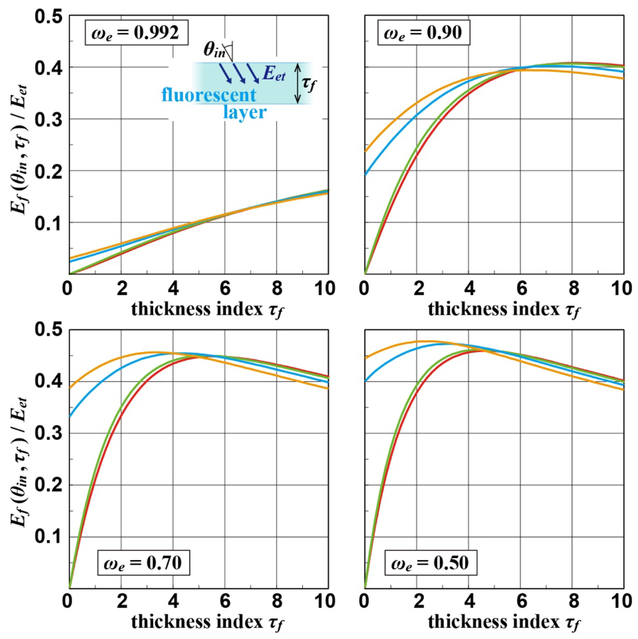
Figure 7 shows the results of three relationships analyzed numerically: incident angle, thickness index of the fluorescent layer, and fluorescence intensity. The reason for this numerical analysis is that the fluorescence intensity is affected by the distance taken by the UV radiation through the fluorescent layer, and this distance depends on the incident angle. When the thickness index of the fluorescent layer was small, the generated fluorescence intensity was highly dependent on the incident angle of the UV radiation. The generated fluorescence intensity was significantly affected by the albedo; the lower the albedo, the greater the absorption of the UV radiation ωe. On the other hand, the generated fluorescence intensity was independent of the incident angle of the UV radiation when the thickness index of the fluorescent layer was greater than τf = 6.0 for any albedo ωe values.
The results shown in Figure 7 indicate that when the thickness index of the two prototype fluorescent layers is too thin, it is difficult to correctly obtain hemispherical transmittance. However, for a comparison of the amount of fluorescence generated when the same fluorescent layer was used in the measurement, the same ratio of fluorescence was generated, with the direction of propagation of the excitation radiation being the same.
Based on Figure 7, to measure the hemispherical transmittance using the proposed system, the thickness index of the fluorescent layer must be greater than that of the prototype. The thickness index can be adjusted by increasing the concentration of the fluorescent layer or increasing the actual thickness of the layer.

5.2. Evaluation of Sunscreens

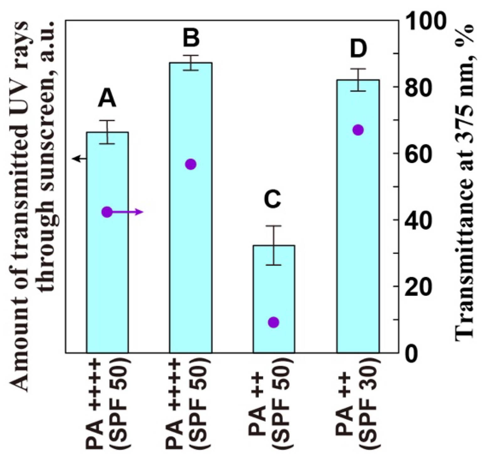
As mentioned above, it is possible to compare the amount of UV energy reaching the fluorescent layer when the same fluorescent layer is used. Therefore, a prototype with a thickness index of approximately 0.4 for the fluorescent layer used in the previous section was tested to evaluate the performance of the sunscreens. The results were compared with those obtained using the classic integrating sphere method. UV radiation at 375 nm was used for this experiment. Because the shielding effect against this wavelength is indicated by the PA or UVAPF values, sunscreens with the same SPF and different PA levels were selected as much as possible. Figure 8 shows the UV transmission characteristics of a 10 µm-thick coating applied onto the fluorescent layer using a film applicator and irradiated with UV radiation and transmittance at 375 nm measured by the classic integrating sphere method. Because it is incorrect to term this result as the hemispherical transmittance, the measured values were labeled as the “amount of transmitted UV” and the unit was set to a.u. Although the proposed measurement method and classical integrating sphere method cannot be directly compared because of the difference in units, results with similar trends were obtained. The measurement results showed that some products claiming UV shielding effectiveness had almost no effect, whereas others had the same shielding effectiveness, even if the PA value was different. This could be attributed to the density of the sunscreen agent. These differences affect the texture and spreadability on the skin or the test plate. This could be the reason why the actual UV transmittance differs even though the same UV shielding level is shown in the package. The effects of sunscreen spreadability and application way onto the evaluation plate on the performance of sunscreens were raised by Wakabayashi et al. [28] This issue needs to be addressed in the future.

6. Conclusions

In this study, a measurement system for the hemispherical transmittance of materials that scatter and absorb UV radiation, such as sunscreens, was proposed. Conventionally, an integrating sphere was used to measure hemispherical transmittance. Here, we proposed a fluorescent material instead of the integrating sphere for conducting hemispherical transmittance measurements and demonstrated the application of the method in the evaluation of sunscreens. The feasibility of the proposed system was verified both numerically and experimentally to evaluate the amount of fluorescence generated by the excitation radiation directly incident on the fluorescent material. Because the excitation radiation passing through the scattering and absorbing material enters the fluorescent material in various directions, for the method to be effective, the thickness index of the fluorescent layer must be increased to 6.0 or more. The thickness index of the fluorescent layer can be increased by increasing its concentration and/or actual thickness.

Supplementary Materials

The following supporting information can be downloaded from https://www.mdpi.com/article/10.3390/app122211521/s1, Figure S1: (a) Absorption spectrum of the UV-G fluorescent material obtained using a spectrophotometer. UV-G was dispersed in water at 0.2 wt% and measured through a 10 mm size quartz cell. V-630BIO (JASCO Corporation, Tokyo, Japan) was used for the measurement. (b) Emission spectrum of the fluorescent material UV-G at an excitation radiation of 375 nm obtained by absolute PL quantum yield measurement; measured using a C9920-02 (Hamamatsu Photonics, Shizuoka, Japan) with air as the reference signal. Figure S2: Graphical description of Equations (7) and (8). Radiation scattering, absorption, and fluorescence emission of the fluorescent layer. These equations and figures illustrate the conservation of radiative energy for a small volume in a medium.

Author Contributions

Conceptualization, writing—original draft preparation, K.N.; validation, T.K.; writing—review and editing, U.M.R.; supervision and funding acquisition, J.Y. All authors have read and agreed to the published version of the manuscript.

Funding

This research was funded by Grants-in-Aid from the Japan Society for the Promotion of Science and Japan Science (grant number:22360090).

Institutional Review Board Statement

Not applicable.

Informed Consent Statement

Not applicable.

Data Availability Statement

Not applicable.

Conflicts of Interest

The authors declare no conflict of interest.

Nomenclature

qradiative flux, W·m−2
Iradiative intensity, W·m−2·sr−1
Eradiation energy, W
Φscattering phase function
Ωsolid angle, sr
θpolar angle, degrees
φazimuthal angle, degrees
nrefractive index
τcoordinate along the direction of the distance and thickness indices of the fluorescent layer
ωalbedo
βextinction coefficient, mm−1
σscattering coefficient, mm−1
αabsorbing coefficient, mm−1
xactual distance, mm
Qfluorescent yield
Rhemispherical reflectance
Themispherical transmittance
Subscripts
sscattering/absorbing sample
eexcitation light
ffluorescent
ttransmitted
inincident

References

  1. Moyal, D. UVA protection labeling and in vitro testing methods, Photochem. Photobiol. Sci. 2010, 9, 516–523. [Google Scholar] [CrossRef] [PubMed]
  2. Sato, K. Sun protection test methods–Current situation and future issues of measurement and labeling of SPF and PA. J. Jpn. Cosmet. Sci. Soc. 2017, 41, 44–48. (In Japanese) [Google Scholar] [CrossRef]
  3. Gollavilli, H.; Hegde, A.R.; Managuli, R.S.; Bhaskar, K.V.; Dengale, S.J.; Reddy, M.S.; Kalthur, G.; Mutalik, S. Naringin nano-ethosomal novel sunscreen creams: Development and performance evaluation. Colloids Surf. B 2022, 193, 111122. [Google Scholar] [CrossRef]
  4. Ionescu, M.A.; Gougerot, A. Sun protection and sunscreen labeling—An update. Acta Dermatovenerol. Croat 2007, 15, 92–95. [Google Scholar]
  5. Code of Federal Regulations. Available online: https://www.ecfr.gov/current/title-21/chapter-I/subchapter-C/part-201/subpart-G/section-201.327#p-201.327(c) (accessed on 1 September 2022).
  6. ISO 24444:2019(en) Cosmetics—Sun Protection Test Methods—In Vivo Determination of the Sun Protection Factor (SPF). Available online: https://www.iso.org/obp/ui/#iso:std:iso:24444:ed-2:v1:en (accessed on 13 September 2022).
  7. ISO 24442:2022(en) Cosmetics—Sun Protection Test Methods—In Vivo Determination of Sunscreen UVA Protection. Available online: https://www.iso.org/obp/ui/#iso:std:iso:24442:ed-2:v1:en (accessed on 13 September 2022).
  8. Lakhdar, H.; Zouhair, K.; Khadir, K.; Essari, A.; Richard, A.; Seité, S.; Rougier, A. Evaluation of the effectiveness of a broad-spectrum sunscreen in the prevention of chloasma in pregnant women. J. Eur. Acad. Dermatol. Venereol. 2007, 21, 738–742. [Google Scholar] [CrossRef]
  9. Ohkubo, K. Integrating sphere theory for measuring optical radiation. J. Light Visual Environ. 2010, 34, 111–122. [Google Scholar] [CrossRef] [Green Version]
  10. Clarke, F.J.J.; Larkin, J.A. Measurement of total reflectance, transmittance and emissivity over the thermal ir spectrum. Infrared Phys. 1985, 25, 359–367. [Google Scholar] [CrossRef]
  11. Pickering, J.W.; Prahl, S.A.; Wieringen, N.; Beek, J.F.; Sterenborg, H.J.C.M.; Gemert, M.J.C. Double-integrating-sphere system for measuring the optical properties of tissue. Appl. Opt. 1993, 32, 399–410. [Google Scholar] [CrossRef]
  12. Roos, A. Use of an integrating sphere in solar energy research. Sol. Energy Mater Sol. Cells 1993, 30, 77–94. [Google Scholar] [CrossRef]
  13. Yaroslavsky, I.V.; Yaroslavsky, A.N.; Goldbach, T.; Schwarzmaier, H.J. Inverse hybrid technique for determining the optical properties of turbid media from integrating-sphere measurements. Appl. Opt. 1996, 35, 6797–6809. [Google Scholar] [CrossRef]
  14. Chin, J.; Byrd, E.; Embree, N.; Garver, J.; Dickens, B.; Finn, T.; Martin, J. Accelerated UV weathering device based on integrating sphere technology. Rev. Sci. Instrum. 2004, 75, 4951–4959. [Google Scholar] [CrossRef]
  15. Gaigalas, A.K.; Wang, L. Measurement of the fluorescence quantum yield using a spectrometer with an integrating sphere detector. J. Res. Natl. Inst. Stand. Technol. 2008, 113, 17–28. [Google Scholar] [CrossRef] [PubMed]
  16. Zhong, M.; Jang, M. Light absorption coefficient measurement of SOA using a UV-Visible spectrometer connected with an integrating sphere. Atmospheric Environ. 2011, 45, 4263–4271. [Google Scholar] [CrossRef]
  17. Rehman, A.; Ahmad, I.; Qureshi, S.A. Biomedical applications of integrating sphere: A review. Photodiagnosis Photodyn. Ther. 2020, 31, 101712. [Google Scholar] [CrossRef] [PubMed]
  18. Pettit, R.B. Hemispherical transmittance properties of solar glazings as a function of averaging procedure and incident angle. So. Energy Mater. 1979, 1, 125–140. [Google Scholar] [CrossRef]
  19. Zerlaut, G.A.; Anderson, T.E. Multiple-integrating sphere spectrophotometer for measuring absolute spectral reflectance and transmittance. Appl. Opt. 1981, 20, 3797–3804. [Google Scholar] [CrossRef]
  20. Kessel, J. Transmittance measurements in the integrating sphere. Appl. Opt. 1986, 25, 2752–2756. [Google Scholar] [CrossRef]
  21. Hanssen, L.M. Effects of non-Lambertian surfaces on integrating sphere measurements. Appl. Opt. 1996, 35, 3597–3606. [Google Scholar] [CrossRef]
  22. Prokhorov, A.V.; Mekhontsev, S.N.; Hanssen, L.M. Monte Carlo modeling of an integrating sphere reflectometer. Appl. Opt. 2003, 42, 3832–3842. [Google Scholar] [CrossRef]
  23. Foschum, F.; Bergmann, F.; Kienle, A. Precise determination of the optical properties of turbid media using an optimized integrating sphere and advanced Monte Carlo simulations. Appl. Opt. 2020, 59, 3203–3215. [Google Scholar] [CrossRef]
  24. Brewster, M.Q. Thermal Radiative Transfer and Properties, 1st ed.; John Wiley & Sons, Inc.: Hoboken, NJ, USA, 1992; pp. 39–53. [Google Scholar]
  25. Hernández-Rivera, D.; Torres-Landa, S.D.; Rangel-Ayala, M.; Agarwal, V. Fluorescent films based on PVDF doped with carbon dots for evaluation of UVA protection of sunscreens and fabrication of cool white LEDs. RSC Adv. 2021, 11, 32604–32614. [Google Scholar] [CrossRef] [PubMed]
  26. Garoli, D.; Pelizzo, M.G.; Nicolosi, P.; Peserico, A.; Tonin, E.; Alaibac, M. Effectiveness of different substrate materials for in vitro sunscreen tests. J. Dermatol. Sci. 2009, 56, 89–98. [Google Scholar] [CrossRef] [PubMed]
  27. Siegel, R.; Howell, J.R. Thermal Radiation Heat Transfer, 3rd ed.; Taylor & Francis: Oxfordshire, UK, 1992; pp. 513–588. [Google Scholar]
  28. Wakabayashi, M.; Okano, K.; Mukawa, T.; Maezawa, D.; Masaki, H.; Kuroda, A.; Asakura, K. Problems on the Evaluation of the Critical Wavelength of Sunscreens for “Broad Spectrum” Approval Brought on by Viscous Fingering During Sunscreen Application. Photochem. Photobiol. 2016, 92, 637–643. [Google Scholar] [CrossRef] [PubMed]
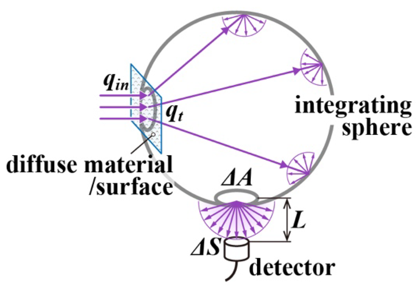
Figure 1. Schematic diagram of transmitted radiation measurement from a diffuser surface using integrating sphere.
Applsci 12 11521 g001
Figure 2. Concept of a measurement method for transmitted radiation.
Applsci 12 11521 g002
Figure 3. Conversion procedure to hemispheric transmittance in the proposed method.
Applsci 12 11521 g003
Figure 4. (a) Detailed view of the site where incident excitation radiation is converted to fluorescence. 1: detector, 2: sharp cut filter, 3: fluorescent layer, 4: glass plate, 5: diffuse material. (b) Experimental configuration for measuring the transmitted radiation. 1: detector, 2: sharp cut filter, 3: measured object, 4: aperture, 5: collimate lens, 6: special filter (pinhole, φ10 μm), 7: light chopper, 8: semiconductor laser.
Applsci 12 11521 g004
Figure 5. Spectral transmittance of the glass slide and UV curable resin used in this study. Both were 1 mm thick, and the V-630BIO spectrophotometer (JASCO Corporation, Tokyo, Japan) was used for the measurements.
Applsci 12 11521 g005
Figure 6. Results of fitting analytical results to experimental results; red square is fluorescent material concentration 33 wt%, green circle is 20 wt%, blue line is fitting for 30 wt% of samples and estimated as τf = 0.35, orange line is fitting for 20 wt% of samples and estimated as τf = 0.18.
Applsci 12 11521 g006
Figure 7. Fluorescence energy emission as a function of thickness index at different values of ωe and different incident angles; θin = 0° in red line, θin = 20° in green line, θin = 40° in blue line, and θin = 60° in orange line.
Applsci 12 11521 g007
Figure 8. Evaluation of the performance of commercial sunscreens; light blue areas indicate the mean amounts of three times measured by the proposed method, the error bars are the standard deviation, and the purple plots indicate the transmittance at 375 nm of each sunscreen obtained by the classical method.
Applsci 12 11521 g008
Table 1. Estimated radiative properties of the fluorescent layer produced in preliminary experiments. ωe is albedo of the fluorescent layer for the excitation radiation; τf is a thickness index of the fluorescent layer; g is the asymmetric factor of the scattering phase function for both excitation radiation and fluorescence.
Fluorescent Material Concentration in Fluorescent Layer
20 wt%30 wt%
ωe0.9920.992
τf0.180.35
g0.750.65
Publisher’s Note: MDPI stays neutral with regard to jurisdictional claims in published maps and institutional affiliations.