Article

Improved MUSIC Method against Range Dimension Deceptive Jamming Based on FDA-MIMO

1
Air and Missile Defense College, Air Force Engineering University, Xi’an 710051, China
2
College of Electronic Science, National University of Defense Technology, Changsha 410000, China
*
Author to whom correspondence should be addressed.
Appl. Sci. 2022, 12(22), 11695; https://doi.org/10.3390/app122211695
Submission received: 7 October 2022 / Revised: 29 October 2022 / Accepted: 14 November 2022 / Published: 17 November 2022

Abstract

:
Frequency diverse array-multiple-input multiple-output (FDA-MIMO) radar makes it transmit beam range–angle two-dimensional freedom by attaching a small frequency offset increment between the array elements. With the widespread use of digital radio frequency memory (DRFM) technology, it is able to delay the false target to any range bin and doppler unit by delaying and forwarding the radar transmits signals, resulting in the deceptive jamming effect of range dimension. To this end, based on the research of the existing main-lobe deceptive interference methods, this paper proposes a new improved MUSIC method based on the FDA-MIMO radar against deceptive jamming in the range dimension. Firstly, the range information of target and jamming is determined through spatial spectrum search by using the mismatch of jamming in the airspace position and range bin position, and then the process of range dimension deceptive jamming suppression is given. The simulation analysis results show that the proposed anti-jamming method can effectively mitigate against range dimension deceptive jamming.

1. Introduction

In the five-in-one high-tech warfare of modern land, sea, air, space, and electricity, the great role of electronic warfare has become increasingly prominent, and even without the right to electromagnetic, it cannot refer to “land, sea, air, space” correctly. The electromagnetic environment is becoming more and more complex, and various types of electromagnetic jamming seriously threaten the normal operation and viability of radar. Therefore, how to guarantee the normal functioning of the radar in the electronic countermeasure environment, and exploring effective anti-jamming methods are the key to defeating the enemy in modern warfare. Phased array provides great anti-jamming potential due to its spatial freedom and flexible beam-pointing ability, and the rapid development of array signal processing technology has also greatly improved the target detection and parameter estimation performance of the phased array, especially in the subspace class algorithms such as the multi-signal classification algorithm [1] (MUSIC), which can improve the super-resolution of the spatial spectrum [2]. The development of digital beamforming technology also makes the beam pattern of phased array generate zero notches at the jamming position and further suppress the jamming performance [3,4]. However, the transmit beam pointing of the phased array is only dependent on the angle parameter, and not on the range parameter. In the range dimension jamming suppression [5,6], the beam pointing needs to change with the range.
Antonik et al. first introduced the concept of Frequency Diverse Array (FDA) at the IEEE Annual Radar Conference in 2006 [7], and then applied for a patent in the US [8]. Unlike phased arrays that can only transmit the same carrier frequency signal, by attaching a frequency offset increment to the array element, which is much smaller than the carrier frequency, the transmitted beam of the FDA has a range–angle that is dimension dependent [9,10]. By combining the FDA with the MIMO radar, it is possible to aggregate information from the transmitter side to the receiver side and to be more flexible in the use of range dimension freedom [11,12], giving the FDA-MIMO radar great potential for applications against main-lobe deceptive interference [13,14,15,16,17,18].
Xu established the model of the FDA deceptive interference signal in [19] and derived its expression. Reference [20] studies beamforming methods based on the direct data domain. However, none of [19,20] consider the effect of time delay, so the interference model is incomplete. Taking into account the effect of time delay, the FDA deceptive jamming model is rederived in [21]. The deceptive interference signal flow is corrected in [22,23], and a new range dimension deceptive interference method is proposed. Yang Chen [24] proposed a composite interference method of suppression and range deception for FDA-MIMO beamforming. References [25,26] proposed a method based on subarray and meshless compressed sensing for evaluating the range parameters information and angle parameters information based on the FDA radar. When multiple signal sources are present, a method to estimate the angle of arrival by phase interferometry is proposed in [27].
Based on the FDA-MIMO radar, reference [19] studied a robust adaptive beamforming algorithm against deceptive jamming, but the steering vector assumed by this method is only a special case among many cases. Reference [28] proposed a dual-pulse detection scheme based on FDA-MIMO, which can ensure a high suppression probability of deceptive jamming. New methods against deceptive interference based on sample selection and non-uniform sample detection are proposed in [29,30]. In [31], a “low-rank + low-rank + sparse” factorization model is used to separate low-rank target signals and suppress deceptive interference signals. Against the range dimension main-lobe deceptive interference, reference [32] proposed a simulated annealing algorithm based on FDA-MIMO. A preset null-broadening beamformer is used in [33] to solve the problem of jamming suppression in case of frequency mismatch. A new weighting design method is proposed in reference [34] to suppress the deceptive interference by using the range dimension degrees of freedom of the FDA to control the location distribution of the zero notches. However, the beamforming anti-jamming methods in [19,29,30,33,34] are easily affected by the signal mismatch caused by incoherent scattering [35], array error [36], direction error [37], and channel gain [38]. For non-uniformly spaced FDA radars, Ge [39] proposed a phase-centric cognitive adaptive anti-interference method. In general, the suppression ability of range dimension deceptive jamming is limited, so it is urgent to study the methods against deception interference in the range dimension.
Based on the FDA-MIMO radar system, this paper studies the range dimension deceptive jamming suppression method. The main innovations are the following:
(1)
The FDA-MIMO deceptive jamming method in the range dimension is analyzed, and an accurate understanding of its interference model is presented.
(2)
An improved MUSIC method against deceptive jamming in the range dimension is proposed.
(3)
A flow chart against deceptive jamming in the range dimension of the FDA-MIMO regime is proposed.
The rest of the article is structured in such a way that the signal models of FDA-MIMO are analyzed in Section 2. Section 3 analyzes the existing range dimension deceptive jamming models and methods. In Section 4, an improved MUSIC method against range dimension deceptive jamming is proposed. Section 5 provides a simulation analysis and validation of the method, and Section 6 concludes the text.

2. The FDA-MIMO Signal Model

Consider a one-dimensional uniform line array with a transmitting array of M elements and a receiving array of N elements. The reference carrier frequency is f 0 and its reference array element is the first array element. The array spacings of the transmitting elements and the receiving elements are d T and d R , respectively, and the speed of light is denoted by c . Its structure is shown in Figure 1.
The frequency offset of the m - th array element of the FDA-MIMO radar is Δ f m , and its transmit frequency is
f m = f 0 + m Δ f ,       m = 0 , 1 ,   . . .   , M 1
For the desired target point P in space, the signal to reach that desired target point can be written as
s m ( t ) = ϕ m ( t ) r e c t ( t T p )   e j 2 π f m t
In Equation (2), T p denotes the pulse duration and ϕ m ( t ) denotes the complex envelope of the m - th transmitted signal. Let us define the function r e c t ( x ) to be
r e c t ( x ) = { 1 ,   0 x 1 0 ,   e l s e
Supposing the range and angle position parameter at a point in space is ( r 0 , θ 0 ) , each array element signal of the FDA-MIMO satisfies the orthogonal condition, with
ϕ m 1 * ( t ) ϕ m 2 ( t τ )   d t = 0 , m 1 m 2 , τ
Then the signal received by the n - th array element after the m - th array element transmits the signal can be written as
s m , n ( t ) = ϕ m ( t τ m , n ) r e c t ( t τ m , n T p )   e j 2 π ( f 0 + Δ f m ) ( t τ m , n )
In Equation (5), τ m , n represents the time delay between the m - th transmitted signal and the n - th received signal.
Assuming the spatial conditions in the far field, these are
τ m , n = 2 r 0 / c ( m d T + n d R ) sin θ 0 / c
Since there is a difference in the phase between the reference array element and the signal of the m - th received array element, Equation (5) can also be approximated as
s m , n ( t ) ϕ m ( t ) r e c t ( t / T p )   e j 2 π f m t e f 0 ( m d T + n d R ) sin θ 0 / c
In Equation (7), t = t 2 r / c is the time index within the pulse, and ϕ m ( t ) can be approximately expressed as
ϕ m ( t ) 2 π [ ( f 0 + Δ f m ) t + f 0 ( m d T + n d R ) sin θ / c ]
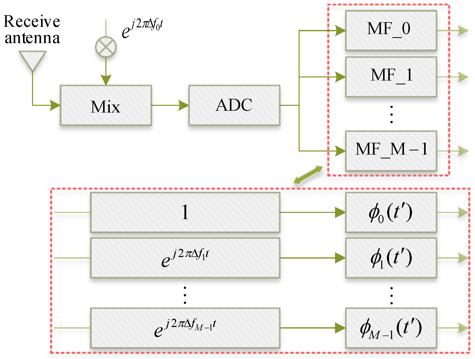
After the radar receiving antenna receives the signal, it performs signal processing on the received signal, and finally, matched filtering is carried out. The signal processing flow at the receiving end is shown in Figure 2.
After signal processing, the signal output from the output can be written as
s m , n ( t ) ξ s r e c t ( t / T p ) e j 4 π f m r 0 / c e j 2 π f 0 ( m d T + n d R ) sin θ 0 / c
In Equation (9), ξ s represents the complex coefficient after processing by the signal processing equipment. After matched filtering, the output signal is only dependent on the range dimension information, but not on the time information, so Equation (9) can again be written as
s m , n = ξ s e j 4 π f m r 0 / c e j π ( m sin θ 0 + n sin θ 0 )
Then, the array factor of the FDA-MIMO radar is
A F = n = 0 N 1 m = 0 M 1 s m , n ( t ) = ξ s r e c t ( t T p ) n = 0 N 1 m = 0 M 1 e j 4 π f m r 0 / c e j 2 π f 0 ( m d T + n d R ) sin θ 0 / c
From Equation (11), we know that the difference in the phase from the reference signal to the m - th transmit signal is range-dependent and independent of the time parameters.
The steering vector is
S = a ( r , θ ) b ( θ )
In Equation (12), is the Kronecker product, a ( r , θ ) and b ( θ ) are the transmitting and receiving steering vectors, respectively, and we have
a ( r , θ ) = [ 1 e j 2 π [ Δ f 1 2 r / c + f 0 d T sin θ / c ] e j 2 π [ Δ f M 1 2 r / c + f 0 ( M 1 ) d T sin θ / c ] ]
b ( θ ) = [ 1 e j 2 π f 0 d R sin θ / c e j 2 π f 0 ( N 1 ) d R sin θ / c ]
Its transmit–receive antenna pattern can be written as
B = | w D H S | 2 = | n = 0 N 1 e j 2 π f 0 n d R ( sin θ sin θ 0 ) c | 2 × | m = 0 M 1 e j 2 π [ Δ f m 2 ( r r 0 ) c + f 0 m d T ( sin θ sin θ 0 ) c ] | 2
At this time, the transmit–receive antenna pattern can be decomposed into the transmit antenna pattern and the receive antenna pattern, and the FDA-MIMO radar scheme using multi-matching filters can generate an antenna pattern related to the range dimension.

3. Model and Method of Range Dimension Deceptive Jamming

3.1. Deceptive Jamming Model for FDA-MIMO

DRFM can generate dummy targets with obvious range offset by sampling, storing, jamming modulation, copying, and forwarding the received signal. The dummy target deceptive jamming produced after DRFM processing can be written as
y m , n = ξ j e j 2 π [ f 0 2 ( r j + Δ r ) c m Δ f 2 ( r j + Δ r ) c + m sin θ j 2 + n sin θ j 2 ] = ξ j e j 2 π [ m Δ f 2 ( r j + Δ r ) c + m sin θ j 2 + n sin θ j 2 ]
where ξ j is the compound coefficient of the interference signal, ξ j = ξ j e j 2 π f 0 2 ( r j + Δ r ) c .
The dummy targets enter the received side of the FDA-MIMO radar and undergo signal processing, the signal processing flow associated with the range parameter is shown in Figure 3.
The range parameter information of the desired target is determined by estimating the range bin, which is mainly defined by pulse repetition period T p and time delay τ , thus
r = mod ( c × τ / 2 , R max )
In Equation (17), mod ( a , b ) denotes the remainder of ( a , b ) . After signal processing at the receiving end, its array factor can be written as
A F = n = 0 N 1 m = 0 M 1 e j 2 π ( m Δ f 2 r c + m sin θ 2 + n sin θ 2 )
After normalizing its antenna pattern, it can be written as
B ( r , θ ) = | w 0 H S ( r , θ ) M N | 2 = | 1 N n = 0 N 1 e j 2 π n ( sin θ sin θ 0 ) 2 | 2 × | 1 M m = 0 M 1 e j 2 π [ m Δ f 2 ( r r 0 ) c + m ( sin θ sin θ 0 ) 2 ] | 2
When the MVDR adaptive beamforming technique is used to analyze the FDA-MIMO radar, it achieves maximum gain at the desired target location and minimum gain at the interference location, that is
G = B ( r , θ ) | r = r s , θ = θ s = | 1 M m = 1 M e 0 | 2 × | 1 N n = 1 N e 0 | 2 = 1
G = B ( r , θ ) | r = r j , θ = θ j = | 1 M m = 1 M e j 2 π ( m 2 Δ r c ) | 2 × | 1 N n = 1 N e 0 | 2 < 1
It can be seen from Equations (20) and (21) that after weighting processing in the FDA-MIMO radar receiver, different range information and angle information of the output signal will result in different gains.

3.2. Range Dimension Deceptive Jamming Method

The existing deceptive jamming can create a significant deceptive interference effect for the FDA-MIMO radar at the range bin estimation level through the range dimensional beam gain over the airspace. The spatial location of the jammer is ( r j , θ j ) , and its intercepted FDA-MIMO radar signal is
s ( t ) = m = 1 M ϕ m ( t τ j 2 τ j , m ) r e c t ( t τ j / 2 τ j , m T p ) e j 2 π f m ( t τ j 2 τ j , m )
In Equation (22), τ j = 2 r j / c denotes the propagation delay, and τ j , m denotes the propagation delay difference among the reference array to the m - th transmitting array.
After the interferer receives the signal transmitted by the radar, it first passes through the power amplifier for power amplification, then after the local oscillator f F T G for down-conversion, and finally performs filtering and other processing. Figure 4 is the signal processing flow at the receiving end of the spoofing interference model.
After filtering the radar-received signal at the receiver end through a filter bank with center frequency p Δ f and bandwidth Δ f , the output signal of the p - th filter can be written as
s 1 ( t ) = φ τ m = 1 M ϕ m ( t τ j / 2 τ j , m ) r e c t ( t τ j / 2 τ j , m T p ) × e j 2 π [ Δ f m ( t τ j 2 τ j , m ) f 0 ( τ j 2 + τ j , m ) ]
In Equation (23), there is p = m M 1 , φ τ denotes the public phase change items. The filter is first matched-filtered for the intercepted signal, and then modulated with a delayed forwarding such as its phase φ j and time delay τ j , where φ j = 2 π Δ f m τ j and τ j = 2 Δ r / c . The final false target is
s 2 ( t ) = A φ m = 1 M ϕ m ( t τ j / 2 τ j , m τ j a m ) r e c t ( t τ j / 2 τ j , m T p ) × e j 2 π [ Δ f m ( t τ j 2 τ j , m τ j a m ) f 0 ( τ j 2 + τ j , m ) + Δ f m τ j a m ]
where A is the amplitude modulation, and φ = φ τ exp { j 2 π f 0 τ j a m } denotes the public phase change items. By mixing with the local oscillator signal and then up-conversion processing, the processed signal is
s 3 ( t ) = A φ τ m = 1 M ϕ m ( t τ j / 2 τ j , m τ j a m ) × r e c t ( t τ j / 2 τ j , m T p ) e j 2 π [ f m ( t τ j 2 τ j , m ) ]
where φ τ denotes the public phase change items after up-conversion. Thus, the signal of the n - th received array element at the receiver is
y j , n = A φ τ m = 1 M ϕ m ( t τ j τ j , m τ j , n τ j a m ) × r e c t ( t τ j τ j , m τ j , n τ j a m T p ) e j 2 π f m ( t τ j τ j , m τ j , n )
where τ j , n denotes the transmission time delay difference among the reference array to the n - th receiving array, and τ j , n = d R n sin θ / c .
In the far-field spatial conditions, the time delay between the n - th received array and the m - th transmitted array is
τ n , m = 2 r j / c n d T sin θ / c m d R sin θ / c
Let τ 0 , 0 = 2 r / c , and r e c t [ ( t τ n , m τ j a m ) / T p ] is approximated as r e c t [ ( t τ 0 , 0 τ j a m ) / T p ] , then Equation (26) be approximated as
y j , n A φ m = 1 M ϕ m ( t ) r e c t ( t T p ) e j 2 π f m ( t 2 r j c ) e j π ( m sin θ j + n sin θ j )
In Equation (28), t = t 2 r / c 2 Δ r / c denotes the pulse time index. After signal processing such as frequency mixing at the receiving end, the matched filter is performed by ϕ m ( t ) within the signal processing device, and the final signal obtained after the matched filter is
y n , m = ξ j 1 e j 4 π f m r j / c e j π ( m sin θ j + n sin θ j ) = ξ j 1 e j 4 π m Δ f r j / c e j π ( m sin θ j + n sin θ j )
where ξ j 1 = ξ j 1 e j 4 π f 0 r j / c , ξ j 1 are the complex coefficients after matched filtering. Consider a self-defending interferer, there are ( r j = r 0 , θ j = θ 0 ) , to detect the desired target, its steering vector is set to
w 0 = S ( r , θ ) | r = r 0 , θ = θ 0 = a ( r 0 , θ 0 ) b ( θ 0 )
The normalized antenna pattern is
B ( r , θ ) = | w 0 H S ( r , θ ) M N | 2 = | 1 M m = 0 M 1 e j 2 π [ m Δ f 2 ( r r 0 ) c + m ( sin θ sin θ 0 ) 2 ] | 2 × | 1 N n = 0 N 1 e j 2 π n ( sin θ sin θ 0 ) 2 | 2
The weight vector of the deceptive jamming signal generated by the jammer is
w j = S ( r , θ ) | r = r 0 , θ = θ 0 = a ( r 0 , θ 0 ) b ( θ 0 )
So, the beam gain is normalized to obtain
G = B ( r , θ ) | r = r 0 , θ = θ 0 = | 1 M m = 1 M e 0 | 2 × | 1 N m = 1 M e 0 | 2 = 1
From Equation (33), we can know that the false target deceptive jamming and the real target can achieve the same large beam gain, and the power of the jamming will not be attenuated after signal processing. By changing the size of the time delay τ , the false target can emerge at various range bins, thereby creating a significant range dimension deceptive interference effect as a way to interfere with the regular operation of radars.

4. Improved MUSIC Method against Range Dimension Deceptive Jamming

The existing deceptive jamming mode can utilize the range dimension degrees of freedom of the FDA-MIMO radar to create a significant deceptive interference effect on the range bin through the beamforming gain in the range dimension, and at this time, it matches the angle and distance parameter information of the desired signal at the beamforming level. When the adaptive beam is focused, the interfering beam will also be focused, but the energy entering the receiver will not be reduced, which leads to the mismatch between the position of the airspace and the position of the range bin. Through a range–angle dimension spatial spectrum search, the angle and distance parameter information of the desired signal and the jamming can be determined by utilizing the mismatch of the range dimension information against deceptive jamming.
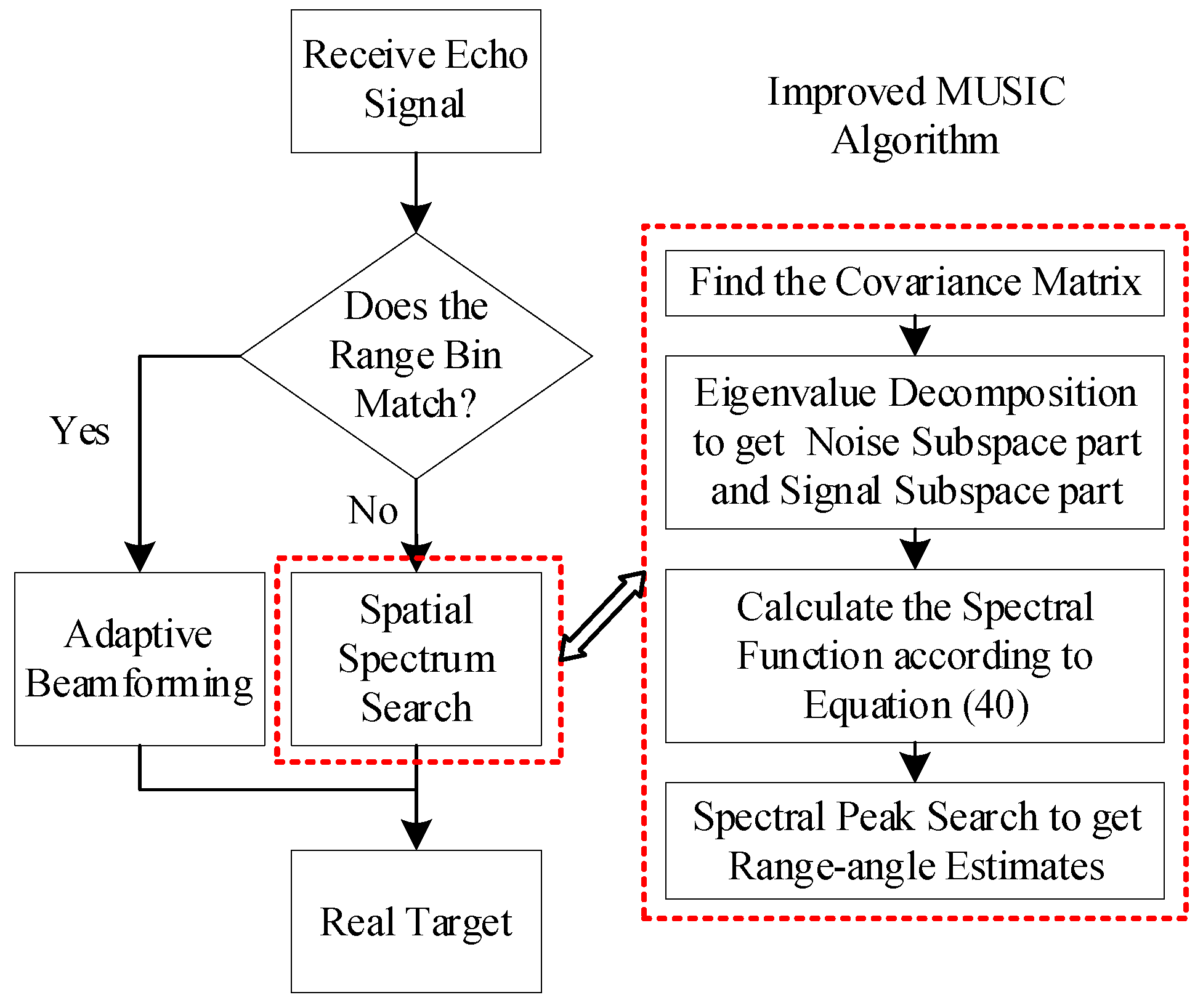
The improved MUSIC algorithm’s basic idea is to first obtain the covariance matrix by maximum likelihood estimation of the received signal, and then perform the eigendecomposition of the covariance matrix to obtain two groups of mutually orthogonal signal subspaces and noise subspaces. Finally, utilizing the orthogonality of the two subspaces, the range and angle information of the received signal are determined by constructing the spatial spectrum function.
The mathematical model of the radar received signal can be written as
s ( t ) = m = 1 M ϕ m ( t τ j 2 τ j , m ) r e c t ( t τ j / 2 τ j , m T p ) e j 2 π f m ( t τ j 2 τ j , m )
where τ j = 2 r j / c denotes the reference propagation delay. For desired targets and false targets in airspace, Equation (34) can also be written as
s ( l ) = s d ( l ) v ( r d , θ d ) + j = 1 K s j ( l ) v ( r j , θ j ) + n ( l )
After receiving the signal at the radar receiver, the covariance matrix can be found:
R x = E ( s s H ) = j = 1 K + 1 α j 2 α ( r d , θ d ) α H ( r d , θ d ) + σ 2 I
where σ 2 denotes the noise signal power, and I denotes the identity matrix of order M × M . Then, the eigendecomposition of R x is carried out. After analyzing the covariance matrix of the noise signal and the desired signal, respectively, we can get the covariance matrix of the noise signal to be
R N = σ 2 I
Decompose R x to get
R ^ x = U U H = [ S , G ] [ S H G H ]
In Equation (38), denotes the vector diagonal array, and takes the first D larger eigenvalues of R x relating to the eigenvector matrix to constitute the signal subspace S , and takes the last M D smaller eigenvalues of R x relating to the eigenvector matrix to constitute the noise subspace G .
To study the relationship between signal subspace S and noise subspace G , multiply both sides of R x by G , and simplify it; there are
R ^ x G = [ S , G ] [ S H G H ] G = [ S , G ] [ O I ] = σ 2 G
The spatial spectrum can be defined as
P ( θ , r ) = α H ( θ , r ) U ^ α ( θ , r ) α H ( θ , r ) G G H α ( θ , r )
where U ^ = σ 2 k = 1 p λ k ( σ 2 λ k ) 2 u k u k H . According to the orthogonality principle of subspace, when the noise subspace part and the signal subspace part are mutually orthogonal, the denominator in Equation (40) is the smallest and P ( θ , r ) reaches the maximum value. At this time, the angle parameter and range parameter information is derived from the coordinates corresponding to the spectral peak position of P ( θ , r ) , and then the target can be located.
Steps to improve MUSIC algorithm:
(1)
Perform maximum likelihood estimation according to the N received signal vectors to obtain the covariance matrix estimate R ^ x ;
(2)
The covariance matrix R ^ x is decomposed into eigenvalues, and then the number of sources is determined according to the eigenvalues;
(3)
Sort the eigenvalues according to the size of eigenvalues, and the noise subspace part and the signal subspace part are obtained;
(4)
The spectral function is calculated according to the formula
P ( θ , r ) = α H ( θ , r ) U ^ α ( θ , r ) α H ( θ , r ) G G H α ( θ , r )
The estimated values of range and angle are obtained by traversing and searching the spectral peaks.
Figure 5 is the flow chart of range dimension deceptive jamming suppression. When the FDA-MIMO radar is interfered at the range bin level and is unable to operate properly, due to the mismatch of range dimension parameter information, the spatial spectrum search can be used to locate the target at this time, determine the range information of the real target and the fake target, and then combined with the adaptive beamforming technology against the range dimension deceptive jamming.

5. Simulation and Analysis

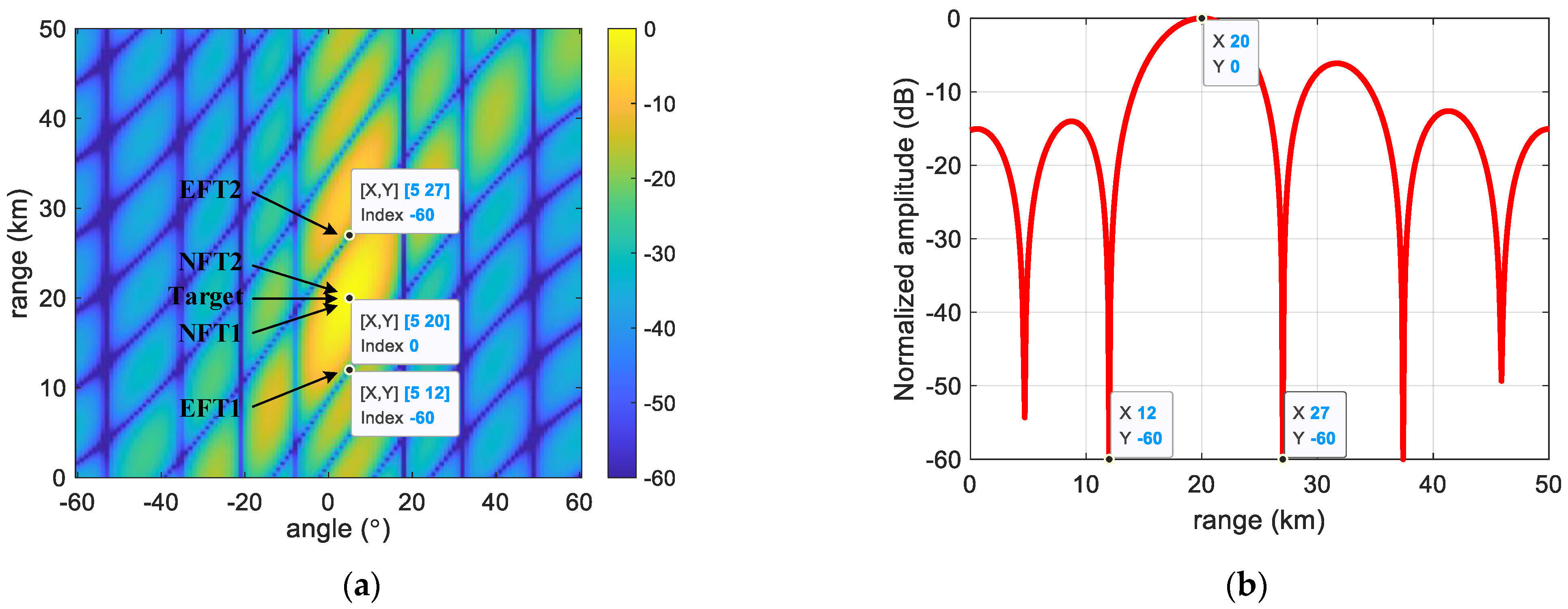
In this section, the proposed anti-jamming method is simulated and validated. The existing deceptive interference false targets are named EFT1 and EFT2, respectively, and new deceptive interference false targets are named NFT1 and NFT2, respectively. Considering that the number of transmit array elements of the radar is M = 10 , the number of receive array elements is N = 10 , the information of the range parameter and angle parameter of the desired target is ( 20   km , 5   ° ) , and the pulse repetition cycle is 0.2   ms , so the maximum blur-free distance is 30   km , and the range bin is set to 300 . Table 1 shows the simulation parameter settings of the FDA-MIMO radar.

5.1. False Target Deceptive Jamming

The distance-angle two-dimensional adaptive beamforming gain of the FDA-MIMO radar is shown in Figure 6. From Figure 6a,b, we can know that the existing deceptive interference EFT1 and EFT2 are located at the sidelobe location of the beam pattern, at which time the beam gain drops sharply, forming a zero notch at this location, while the new deceptive jamming NFT1 and NFT2 are located at the same gain location as the real target, and the beam gain obtained is as high as the target.
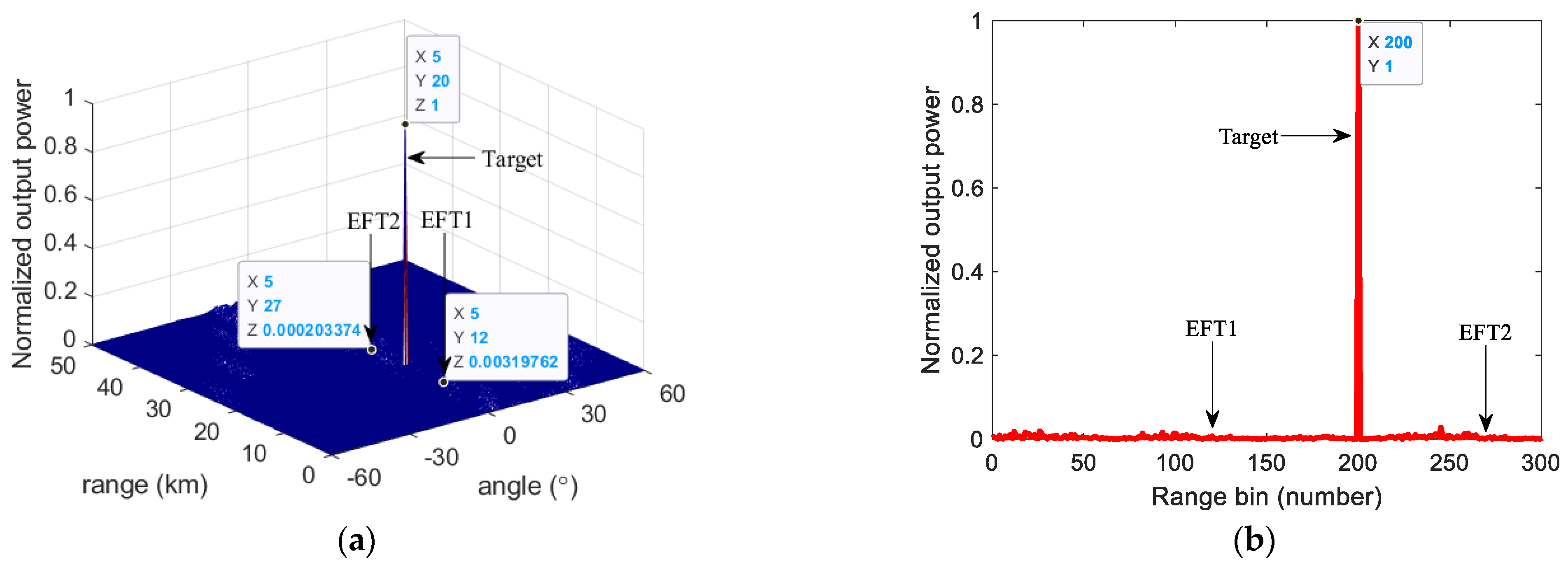
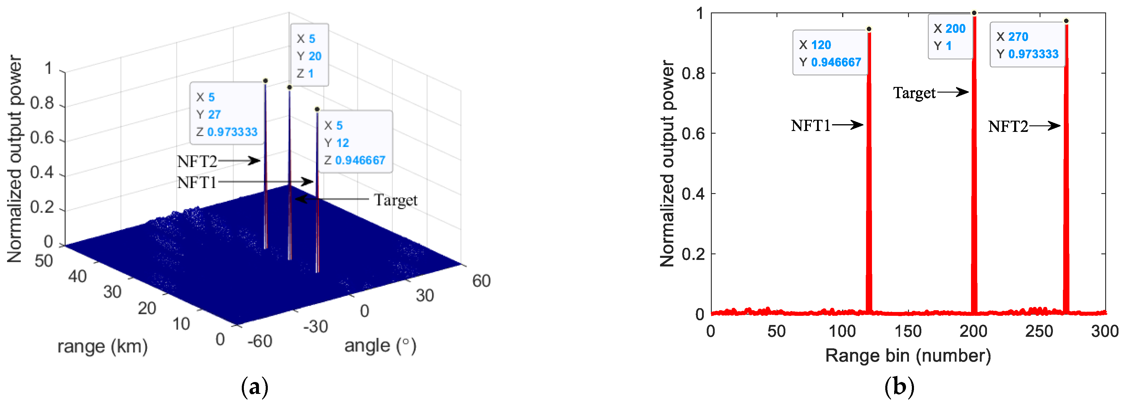
The output power of the range–angle two-dimensional adaptive matched filter for existing false targets and new deceptive interference is shown in Figure 7 and Figure 8, respectively. As can be seen from Figure 7a and Figure 8a, the output power of existing deceptive interference EFT1 and EFT2 is greatly weakened, and its power magnitude is not much different from the power of ordinary noise. The new deceptive interference NFT1 and NFT2 have the same large power as the real targets, which is almost unaffected by the adaptive beam.
The range bin analysis results of existing deceptive interference and new deceptive interference are shown in Figure 7b and Figure 8b, respectively. From Figure 7b and Figure 8b, we also can observe that the output power of the existing deceptive interference EFT1 and EFT2 are greatly weakened, the new deceptive interference NFT1 and NFT2 can effectively influence the range bin of the FDA-MIMO radar, and the interference can appear at any range bin, which can form an effective deceptive jamming effect.

5.2. Improve MUSIC Method against Range Dimension Deceptive Jamming

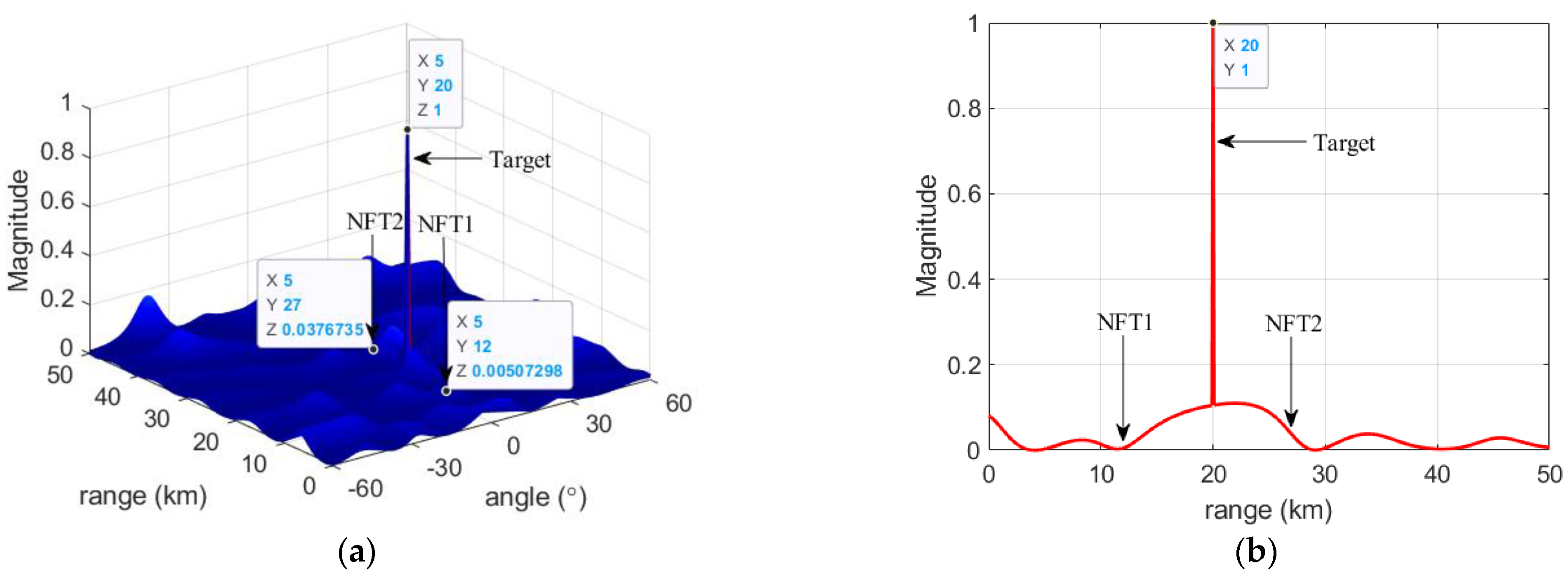
The spatial spectra of the desired targets and the existing false targets are shown in Figure 9. From Figure 9, we can detect that the existing deceptive interference EFT1 and EFT2 have the same large output power as the real targets. The spatial spectra of the desired targets and the new deceptive jamming are shown in Figure 10. From Figure 10, we can see that the output power of the new deceptive jamming NFT1 and NFT2 has been severely suppressed. By performing the range–angle two-dimensional spatial spectrum search in the airspace, the beamforming gain of the desired targets has hardly changed at this time, and it can still obtain large output power, while the deceptive jamming NFT1 and NFT2 have been suppressed because of the mismatch of distance dimensional information.
Since the FDA-MIMO radar has range–angle two-dimensional freedom, the energy of deceptive jamming NFT1 and NFT2 is not lost when they influence the range bin of the FDA-MIMO radar, which causes a mismatch between the range displayed by the range bin and the equivalent range between the airspace where the target is located, so after the range–angle two-dimensional spatial spectrum search, it can be effective against the range dimension deceptive jamming.
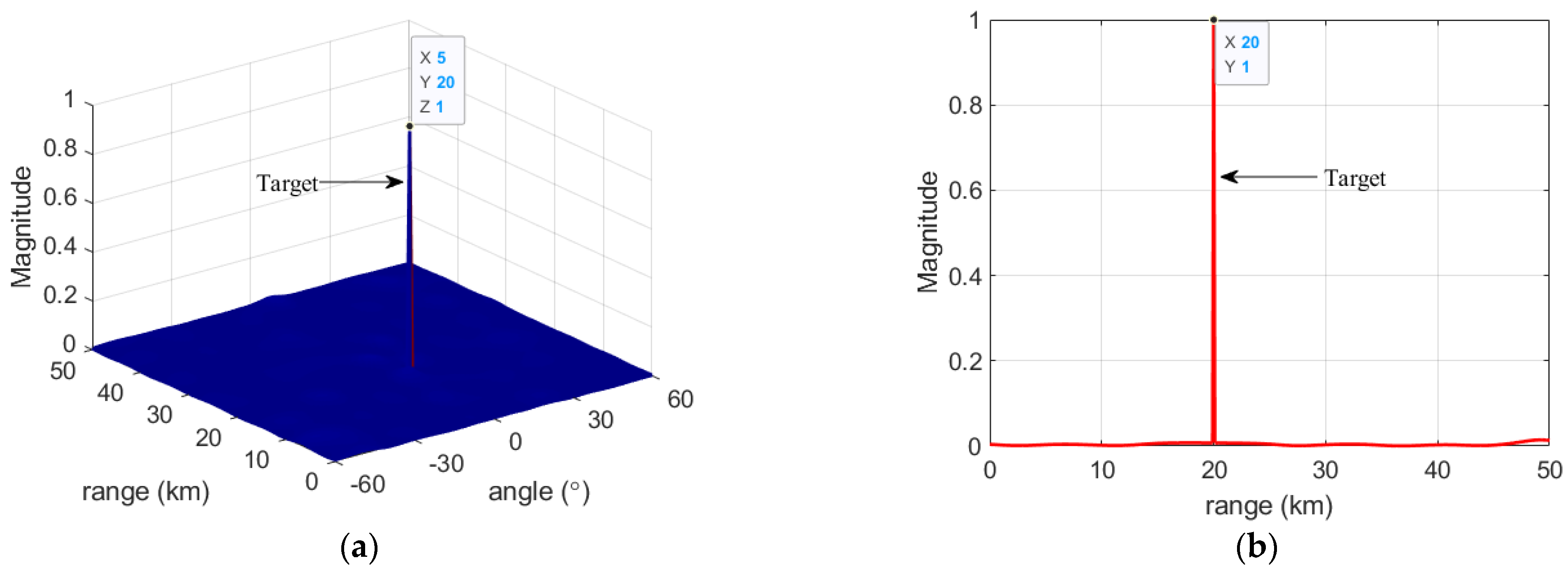
Figure 11 shows the spatial spectrum of four false targets and desired targets after passing through the adaptive beam. From Figure 11, we can observe that the beamforming gain of the real targets has hardly changed at this time, while the output power of the existing deceptive interference and the new deceptive interference has been severely suppressed, which can no longer develop an effective deceptive interference result. By combining the spatial spectrum search technology and the adaptive beamforming technology, it can be effective against the range dimension deceptive jamming, and the problem of range dimension deceptive jamming suppression can be solved.

5.3. Performance Analysis

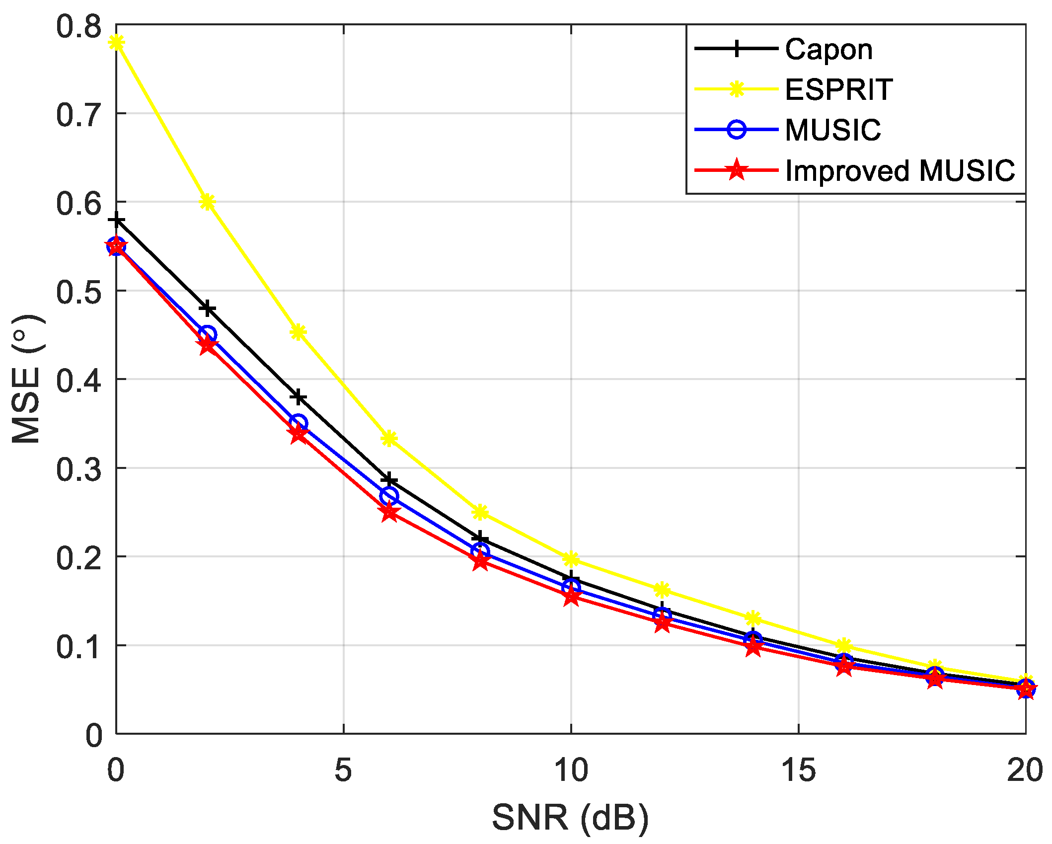
Figure 12 shows the variation trend of the mean square error (MSE) of several spectrum estimation algorithms with SNR. As can be seen from Figure 12, the MSE of several algorithms gradually decreases as the SNR increases. The ESPRIT algorithm has the highest MSE, the Capon algorithm and MUSIC algorithm are in the middle, and the proposed improved MUSIC algorithm has the lowest MSE. The performance of the proposed improved MUSIC algorithm is better than the other algorithms.

6. Conclusions

In this paper, an improved MUSIC method against range dimensional deceptive interference is proposed based on the FDA-MIMO radar system. When the false targets deceive the range dimension of the FDA-MIMO radar, there is a mismatch between the equivalent position of the airspace and the position shown by the range bin. Therefore, based on the full study of the existing range dimension deceptive jamming methods, this paper firstly constructs the covariance matrix for the radar received signal, then obtains the signal subspace and noise subspace through eigenvalue decomposition, and then obtains the range parameter information of the desired targets and jamming through spatial-spectral search. Finally, combined with FDA-MIMO adaptive beamforming technology, the problem of range dimension false targets deceptive jamming suppression can be effectively solved. The contribution of this study is to propose a range dimension deceptive jamming suppression method, which provides a new idea for the anti-jamming of the new system radar, and the subsequent study can be combined with multi-domain joint anti-jamming.

Author Contributions

Conceptualization, Y.C. and B.T.; methodology, Y.C. and Y.Z.; software, Y.C. and J.G.; validation, Y.C. and B.T.; data curation, Y.C. and C.W.; writing—original draft preparation, Y.C.; writing—review and editing, Y.C. and B.T.; supervision, C.W.; funding acquisition, J.G. All authors have read and agreed to the published version of the manuscript.

Funding

This work was supported by the Natural Science Foundation of Shaanxi Province under grant 2021JM-222 and the China Postdoctoral Science Foundation under grant 2019M662257.

Institutional Review Board Statement

Not applicable.

Informed Consent Statement

Not applicable.

Data Availability Statement

The data presented in this study are available on request from the corresponding author.

Conflicts of Interest

The authors declare no conflict of interest.

References

  1. Stoica, P. MUSIC, Maximum Likelihood, and Cramer-Rao Bound. IEEE Trans. Acoust. Speech Signal Process. 1989, 37, 720–741. [Google Scholar] [CrossRef]
  2. Liu, F.; Wang, X.; Huang, M.; Wan, L. Joint angle and range estimation for bistatic FDA-MIMO radar via real-valued subspace decomposition. Signal Process. 2021, 185, 108065. [Google Scholar] [CrossRef]
  3. Yang, X.; Zhang, Z.; Zeng, T.; Long, T.; Sarkar, T. Mainlobe Interference Suppression Based on Eigen-Projection Processing and Covariance Matrix Reconstruction. IEEE Antennas Wirel. Propag. Lett. 2014, 13, 1369–1372. [Google Scholar] [CrossRef]
  4. Feng, Y.; Liao, G.; Xu, J.; Zhu, S.; Zeng, C. Robust adaptive beamforming against large steering vector mismatch using multiple uncertainty sets. Signal Process. 2018, 152, 320–330. [Google Scholar] [CrossRef]
  5. Lan, L.; Xu, J.; Zhu, S.; Liao, G.; Zhang, Y. Advances in anti-jamming using waveform diverse array radar. Syst. Eng. Electron. 2021, 43, 1437–1451. [Google Scholar]
  6. Lan, L.; Liao, G.; Xu, J.; Zhang, Y. Main-beam range deceptive jamming suppression approach with FDA-MIMO radar. Syst. Eng. Electron. 2018, 40, 997–1003. [Google Scholar]
  7. Antonik, P.; Wicks, M.C.; Griffiths, H.D.; Baker, C.J. Frequency diverse array radars. In Proceedings of the 2006 IEEE Conference on Radar, Verona, NY, USA, 24–27 April 2006; pp. 215–217. [Google Scholar]
  8. Wicks, M.C.; Antonik, P. Frequency Diverse Array with Independent Modulation of Frequency, Amplitude, and Phase. U.S. Patent US11312805, January 2008. [Google Scholar]
  9. Wang, W. Range-Angle Dependent Transmit Beampattern Synthesis for Linear Frequency Diverse Arrays. IEEE Trans. Antennas Propag. 2013, 61, 4073–4081. [Google Scholar] [CrossRef]
  10. Xu, J.; Zhu, S.; Liao, G.; Zhang, Y. An Overview of Frequency Diverse Array Radar Technology. J. Radars 2018, 7, 167–182. [Google Scholar]
  11. Sammartino, P.F.; Baker, C.J.; Griffiths, H.D. Frequency diverse MIMO techniques for radar. IEEE Trans. Aerosp. Electron. Syst. 2013, 49, 201–222. [Google Scholar] [CrossRef]
  12. Xu, J.; Liao, G.; Zhu, S.; Huang, L.; So, H.C. Joint Range and Angle Estimation Using MIMO Radar with Frequency Diverse Array. IEEE Trans. Signal Process. 2015, 63, 3396–3410. [Google Scholar] [CrossRef]
  13. Wan, P.; Weng, Y.; Xu, J.; Liao, G. Range Gate Pull-Off Mainlobe Jamming Suppression Approach with FDA-MIMO Radar: Theoretical Formalism and Numerical Study. Remote Sens. 2022, 14, 1499. [Google Scholar] [CrossRef]
  14. Huang, L.; Zong, Z.; Zhang, S.; Wang, W. 2-D Moving Target Deception against Multichannel SAR-GMTI Using Frequency Diverse Array. IEEE Geosci. Remote Sens. Lett. 2022, 19, 1–5. [Google Scholar] [CrossRef]
  15. Liu, W.; Liu, J.; Hao, C.; Gao, Y.; Wang, Y. Multichannel adaptive signal detection: Basic theory and literature review. Sci. China Inf. Sci. 2022, 65, 5–44. [Google Scholar] [CrossRef]
  16. Chen, H.; Liu, Y.; Lv, M.; Zhang, X.; Xia, B.; Xie, D. Networked FDA-MIMO radar positioning to suppress dense false target jamming. J. Phys. Conf. Ser. 2021, 1920, 012061. [Google Scholar] [CrossRef]
  17. Ding, Z.; Xie, J.; Wang, B.; Zhang, H. Robust Adaptive Null Broadening Method Based on FDA-MIMO Radar. IEEE Access. 2020, 8, 177976–177983. [Google Scholar] [CrossRef]
  18. Zhou, C.; Wang, C.; Gong, J.; Tan, M.; Zhao, Y.; Liu, M. FDA-MIMO Beampattern Synthesis with an Analytical Method. Int. J. Aerosp. Eng. 2021, 2021, 9051131. [Google Scholar] [CrossRef]
  19. Xu, J.; Liao, G.; Zhu, S.; So, H.C. Deceptive jamming suppression with frequency diverse MIMO radar. Signal Process. 2015, 113, 9–17. [Google Scholar] [CrossRef]
  20. Xu, J.; Xu, Y.; Liao, G. Direct data domain based adaptive beamforming for FDA-MIMO radar. In Proceedings of the 2016 IEEE Statistical Signal Processing Workshop (SSP), Palma de Mallorca, Spain, 1–5 June 2016. [Google Scholar]
  21. Shi, J.; Liu, X.; Yang, Y.; Sun, S.; Wang, N. Comments on “Deceptive jamming suppression with frequency diverse MIMO radar”. Signal Process. 2019, 158, 1–3. [Google Scholar] [CrossRef]
  22. Tan, M.; Wang, C.; Xue, B.; Xu, J. A Novel Deceptive Jamming Approach against Frequency Diverse Array Radar. IEEE Sens. J. 2021, 21, 8323–8332. [Google Scholar] [CrossRef]
  23. Zhao, Y.; Tian, B.; Wang, C.; Gong, J.; Tan, M.; Zhou, C. Research on main-lobe deceptive jamming against FDA-MIMO radar. IET Radar Sonar Navig. 2021, 15, 641–654. [Google Scholar] [CrossRef]
  24. Chen, Y.; Tian, B.; Wang, C.; Gong, J.; Zhao, Y. Research on the Compound Jamming Method against FDA-MIMO Beamforming. Appl. Sci. 2022, 12, 9448. [Google Scholar] [CrossRef]
  25. Wang, W. Subarray-based frequency diverse array radar for target range-angle estimation. IEEE Trans. Aerosp. Electron. Syst. 2014, 50, 3057–3067. [Google Scholar] [CrossRef]
  26. Tang, W.; Jiang, H.; Zhang, Q. Range-Angle Decoupling and Estimation for FDA-MIMO Radar via Atomic Norm Minimization and Accelerated Proximal Gradient. IEEE Signal Process. Lett. 2020, 27, 366–370. [Google Scholar] [CrossRef]
  27. Antonello, F.; Gianfranco, A.; Giuseppe, C. Multiple Source Angle of Arrival Estimation through Phase Interferometry. IEEE Trans. Circuits Syst. II Express Briefs 2022, 69, 674–678. [Google Scholar]
  28. Tang, S.; Zhang, L.; Liu, N.; Zhang, J.; Zhao, S. Adaptive detection with conic rejection to suppress deceptive jamming for frequency diverse MIMO radar. Digital Signal Process. 2017, 69, 32–40. [Google Scholar]
  29. Xu, J.W.; Kang, J.L.; Liao, G.S.; So, H.C. Mainlobe Deceptive Jammer Suppression with FDA-MIMO Radar. In Proceedings of the IEEE 10th Sensor Array and Multichannel Signal Processing Workshop (SAM), Sheffield, UK, 8–11 July 2018; pp. 504–508. [Google Scholar]
  30. Lan, L.; Liao, G.; Xu, J.; Zhang, Y.; Fioranelli, F. Suppression Approach to Main-Beam Deceptive Jamming in FDA-MIMO Radar Using Nonhomogeneous Sample Detection. IEEE Access. 2018, 6, 34582–34597. [Google Scholar] [CrossRef]
  31. Liu, Q.; Xu, J.; Ding, Z. Target Localization with Jammer Removal Using Frequency Diverse Array. IEEE Trans. Veh. Technol. 2020, 69, 11685–11696. [Google Scholar] [CrossRef]
  32. Wang, Y.; Zhu, S. Main-Beam Range Deceptive Jamming Suppression with Simulated Annealing FDA-MIMO Radar. IEEE Sens. J. 2020, 20, 9056–9070. [Google Scholar] [CrossRef]
  33. Lan, L.; Xu, J.; Liao, G.; Zhang, Y.; Fioranelli, F.; So, H. Suppression of Mainbeam Deceptive Jammer with FDA-MIMO Radar. IEEE Trans. Veh. Technol. 2020, 69, 11584–11598. [Google Scholar] [CrossRef]
  34. Liao, Y.; Tang, H.; Chen, X.; Wang, W.; Xing, M.; Zheng, Z.; Wang, J.; Liu, Q. Antenna Beampattern with Range Null Control Using Weighted Frequency Diverse Array. IEEE Access. 2020, 8, 50107–50117. [Google Scholar] [CrossRef]
  35. Zhang, J.; Xue, Y.; Kang, J.; Chen, D.; Wan, Q. Robust adaptive beamforming under data dependent constraints. Signal Process. 2021, 188, 108202. [Google Scholar] [CrossRef]
  36. Chen, P.; Yang, Y.; Wang, Y.; Ma, Y. Robust Adaptive Beamforming with Sensor Position Errors Using Weighted Subspace Fitting-Based Covariance Matrix Reconstruction. Sensors 2018, 18, 1476. [Google Scholar] [CrossRef] [PubMed] [Green Version]
  37. Zhang, X.; He, Z.; Liao, B.; Zhang, X.; Peng, W. Robust quasi-adaptive beamforming against direction-of-arrival mismatch. IEEE Trans. Aerosp. Electron. Syst. 2018, 54, 1197–1207. [Google Scholar] [CrossRef]
  38. Yao, D.; Zhang, X.; Hu, B.; Yang, Q.; Wu, X. Robust Adaptive Beamforming with Optimal Covariance Matrix Estimation in the Presence of Gain-Phase Errors. Sensors 2020, 20, 2930. [Google Scholar] [CrossRef] [PubMed]
  39. Ge, J.; Xie, J.; Wang, B. A Cognitive Active Anti-jamming Method Based on Frequency Diverse Array Radar Phase Center. Digital Signal Process. 2021, 109, 102915. [Google Scholar] [CrossRef]
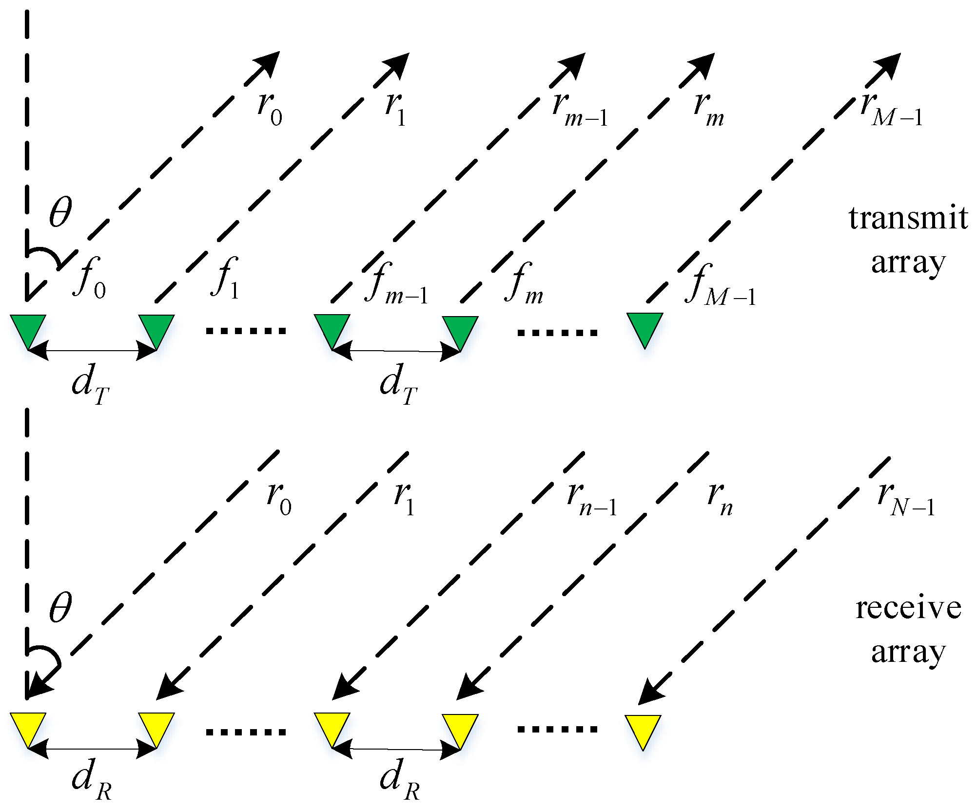
Figure 1. The FDA-MIMO radar structure diagram.
Applsci 12 11695 g001
Figure 2. Signal processing flow at the receiving end.
Applsci 12 11695 g002
Figure 3. The signal processing flow of the FDA-MIMO radar receiving end associated with the range parameter.
Applsci 12 11695 g003
Figure 4. Receiver processing flow chart of the spoofing interference model.
Applsci 12 11695 g004
Figure 5. The range dimension deceptive interference suppression flow chart.
Applsci 12 11695 g005
Figure 6. The distance-angle two-dimensional adaptive beamforming gain of the FDA-MIMO radar. (a) Three-dimensional beamforming gain; (b) Two-dimensional beamforming gain at the main lobe.
Applsci 12 11695 g006
Figure 7. The range–angle two-dimensional adaptive matched filter output power of the existing false targets. (a) Three-dimensional beamforming gain; (b) Range bin analysis results.
Applsci 12 11695 g007
Figure 8. The range–angle two-dimensional adaptive matched filter output power of new deceptive jamming. (a) Three-dimensional beamforming gain; (b) Range bin analysis results.
Applsci 12 11695 g008
Figure 9. Spatial spectra of existing false targets and desired targets for FDA-MIMO. (a) Spatial spectral distribution of range–angle two-dimensional; (b) Range profile.
Applsci 12 11695 g009
Figure 10. Spatial spectra of new deceptive jamming and desired targets for the FDA-MIMO radar. (a) Spatial spectral distribution of range–angle two-dimensional; (b) Range profile.
Applsci 12 11695 g010
Figure 11. The spatial spectrum of four false targets and desired targets after passing through the adaptive beam. (a) Range–angle two-dimensional spatial-spectral distribution; (b) Range profile.
Applsci 12 11695 g011
Figure 12. The variation trend of MSE with SNR.
Applsci 12 11695 g012
Table 1. The FDA-MIMO simulation parameters.
ParametricNumberParametricNumber
Carrier frequency f 0 = 9   GHz Frequency offset Δ f = 1   kHz
Array elements M = N = 10 Snapshot 2000
Pulse repetition cycle T = 0.2   ms Range bin 300
Target position ( 20   km , 5   ° ) SNR 10   dB
Target delay τ 0 = 0.05   ms JNR 20   dB
EFT1 delay τ 1 = 0.0733   ms EFT2 delay τ 2 = 0.1233   ms
NFT1 delay τ 1 = 0.0733   ms NFT2 delay τ 2 = 0.1233   ms
Publisher’s Note: MDPI stays neutral with regard to jurisdictional claims in published maps and institutional affiliations.