Abstract
Our aim in this study was to analyze the major and minor factors affecting the stability of a slope containing a coal seam in a goaf. Based on engineering experience, we first identified nine factors that may affect slope stability, of which we determined eight that may substantially affect slope stability through a single-factor numerical simulation analysis. Then, we arranged 27 groups of numerical simulation tests with eight factors and three levels with the orthogonal test method, and we determined the ranking of the major and minor influencing factors through a range of variance analyses. The results showed that the influence of each factor was ranked as the roadway width > coal seam position > slope gradient > coal seam thickness > coal seam internal friction angle > coal seam cohesion > coal seam dip angle. Among these, the roadway width, coal seam position, and slope gradient were the major factors affecting slope stability; coal seam thickness, coal seam internal friction angle, coal seam cohesion, and coal seam dip angle were the minor factors. In this study, we combined the goaf and slope containing the coal seam, and we couple analyzed the factors influencing the stability of the slope containing the coal seam in the goaf. Our findings provide a scientific basis for the treatment and protection of slopes containing coal seams in goafs in the future and have a practical engineering importance for the analysis of the excavation stability of road-cutting slopes in goafs.
1. Introduction
A slope containing a coal seam in a goaf is a slope formed when the unmined coal seam is exposed to the surface of the slope, during the process of excavation in the goaf, as shown in Figure 1. Recently, with the large-scale construction of highway projects in China, highways are increasingly passing through goafs, so excavation for road cutting in goafs is required. When the road slope contains shallow unmined coal seams, the slope is prone to collapse, which affects the normal construction and operation of the highway, and even threatens human safety and lives. Therefore, analyzing the factors influencing the goaf slopes containing a coal seam is essential.
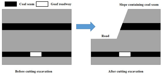
Figure 1.
Formation process of a slope containing a coal seam in goafs.
To address the problem of slope stability, the current research directions mainly include: (1) new methods for analyzing slope stability, such as for calculating the slope stability, based on the generalized Hoek–Brown criterion [1], for predicting the slope stability, based on the finite element analysis and field data superposition [2], and for predicting the slope stability, based on machine learning [3]; (2) a slope stability analysis of various special soils, such as expansive soil [4,5], unsaturated soil [6], soft soil [7], etc.; (3) a slope stability analysis under various special conditions, such as earthquake [8] and rainfall conditions [9,10]; (4) measures for slope reinforcement, such as planting plants [11,12], injecting a curing liquid [13], etc. Regarding the stability of goafs, the current research directions are mainly focused on: (1) the subsidence prediction of goafs, such as a numerical simulation subsidence prediction [14] and intelligent subsidence predictions using computers [15], etc.; (2) the scope of the goaf detection, to detect water-logged [16] and old goafs [17]; (3) goaf treatment methods, such as the application of fly ash geopolymer grouting material [18] and the grouting method when the goaf is saturated with water [19]; (4) the influence of various special working conditions on the stability of goafs, such as under water static–dynamic load coupling [20] and under earthquake loads [21].
Many studies have focused on the stability of goafs or slopes, but studies are lacking on the stability of goaf slopes. Considering the stability of a goaf slope, Xie et al. [22] studied the influence of the underlying goaf on an open-pit slope, based on various methods, such as a finite element analysis and mechanical theoretical calculation, and the results showed that the instability and collapse of the goaf roof would lead to the local collapse of the open-pit slope. To study the influence of the goaf span, position, and double-layer goaf working conditions on slope stability, Xu et al. [23] applied ANSYS software to establish several models, and finally came to the conclusion that all three working conditions would lead to the decline of the slope stability coefficient. To explore the instability mechanism of a red clay slope under the influence of a goaf, Li et al. [24] revealed the instability and failure development law of this type of slope by combining a numerical simulation analysis with the limit equilibrium theory. The results showed that the instability and failure mechanism of the red clay slope was a ’shear-tensile crack-slip-collapse’. To solve the problem of complicated processes and a low accuracy in the safety evaluation of the goaf slope, Zhao et al. [25] established a risk evaluation model of the goaf slope using the TOPSIS theory. The results show that the evaluation results of the established model are consistent with reality, and can better evaluate the state of the goaf slope. Zhang et al. [26], to explore the slope instability process, analyzed the damage, failure, and instability processes of a localized rock mass in the process of multiple minings of a multistage slope, based on the RFPA finite element software. The results showed that the continuous mining of a multistage slope was mainly characterized by local instability and failure, under the influence of time and space effects. Through the above analysis, we found that scholars have studied the stability of goaf slopes, but have mostly focused on the influence of coal seam mining on the stability of the existing slopes that do not contain coal seams. The stability of a goaf slope with a coal seam has not been analyzed.
Based on this, in this study, we considered the excavation of a cutting slope containing a coal seam in the K1641 + 890–K1641 + 950 section of the Jixi Section reconstruction and expansion project of the National Dan-A Highway. We used three-dimensional finite element software Midas GTS as the calculation engine, selected the slope stability coefficient as the analysis index, and identified the factors influencing a slope containing a coal seam stability in a goaf through a single-factor analysis. We quantitatively evaluated the importance of these stability-influencing factors with the orthogonal test method, and then identified the main and minor factors controlling the slope stability. Our results provide a reference for the treatment of coal seams containing a slope in a goaf, so as to improve the slope stability coefficient.
The rest of this paper is structured as follows: Section 1 introduces our preparatory work, prior to the establishment of the model, including outlining the possible factors influencing slope stability, the method of calculating the stability coefficient, and the model parameters. Section 2 introduces the modeling process, the related settings, and the stability analysis results under actual working conditions. Section 3 describes the process of analyzing the major and minor influencing factors. Section 4 outlines the novelty of the findings and the study results, and provides a discussion of the study shortcomings. Section 5 describes the conclusions of this study.
2. Model Analysis of a Slope Containing a Coal Seam in a Goaf
2.1. Influencing Factors and the Rock Mass Mechanical Parameters
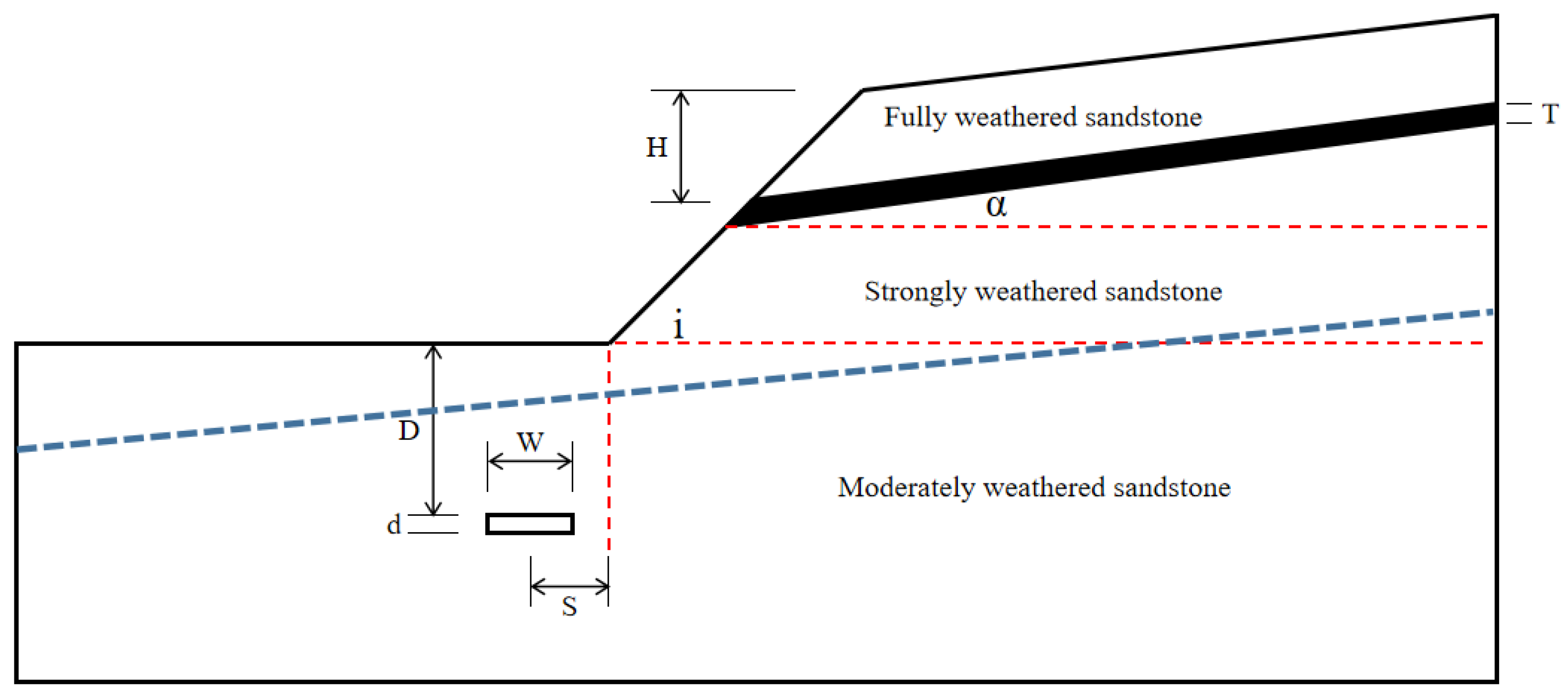
To analyze the factors influencing the stability of a slope containing a coal seam in a goaf, we designed a generalized model, based on an actual project: the K1641 + 890–K1641 + 950 section of the Jixi Section of the Dan-A-Highway reconstruction and expansion project (hereinafter referred to as the actual project), as shown in Figure 2, where i is the slope gradient, T is the coal seam thickness, α is the coal seam dip angle, H is the coal seam position (that is, the distance between the coal seam exposed on the slope surface and the top of the slope), S is the roadway position (that is, the horizontal distance between the roadway center and the slope foot), and W is the roadway width. In addition to the influencing factors shown in Figure 2, we considered the coal seam cohesion c, the coal seam internal friction angle , and the mining depth and mining thickness ratio R (R = D/d) in this study.
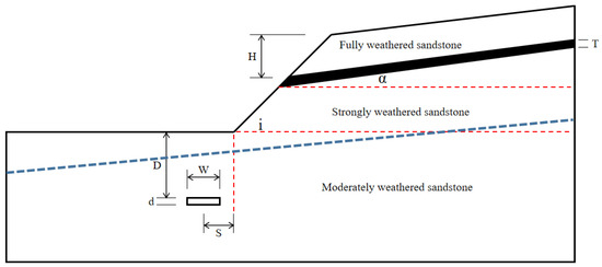
Figure 2.
Schematic diagram of the influencing factors. i is the slope gradient, T is the coal seam thickness, α is the coal seam dip angle, H is the coal seam position (that is, the distance between the coal seam exposed on the slope surface and the top of the slope), S is the roadway position (that is, the horizontal distance between the roadway center and the slope foot), and W is the roadway width. Blue dotted line is the boundary line of the rock strata.
The main rock strata of the slope included strongly weathered sandstone, a coal seam, and moderately weathered sandstone. We determined mechanical rock mass parameters of the slope model according to the laboratory test parameters of the rock mass mechanics of the actual project. The parameters of each rock stratum are shown in Table 1.

Table 1.
Rock mechanics parameters of the model.
2.2. Influencing Factors and the Rock Mass Mechanical Parameters
To calculate the slope stability coefficient, we used Midas GTS software, which uses the strength reduction method to continuously reduce the strength parameters of the rock and soil mass, namely the cohesion and internal friction angle, until the soil is destroyed. The final reduced ratio is the slope stability coefficient. The calculation formulae are as follows:
where are the cohesive force before and after the reduction, respectively; are the internal friction angles before and after the reduction, respectively.
During the calculation of the slope stability coefficient of the model, the Mohr–Coulomb yield criterion is adopted to judge the failure of the rock mass, that is, the cohesion and internal friction angle of the rock and soil mass are the factors that determine its shear failure. The calculation is shown in Formula (3). When the size of the shear stress exceeds the shear stress controlled by the cohesion and the internal friction angle of the rock and soil mass, the rock and soil mass experience shear failure.
here, is the shear stress, is the maximum principal stress, and is the minimum principal stress.
2.3. Model Parameter Analysis
To study the influence of various factors on the stability of a slope containing a coal seam in a goaf, we first needed to design a basic model and calculate the stability coefficient of the model, to verify the accuracy of the model. Taking an actual project as an example, we established a basic simulation analysis model. The parameter values of the basic model were as follows: the slope height was 15 m, the slope gradient i was 45°, the coal seam thickness T was 2 m, the seam inclination α was −10°, the coal seam position H is 7.0 m, the coal seam cohesion c is 11 kPa, the roadway position S was 2.5 m, the friction angle was 16°, the ratio of the mining depth to thickness R was 10, and the roadway width W was 6.5 m. We applied the physical and mechanical parameters of the rock and coal seam, according to the data in Table 1.
Whether the model parameters are reasonably set, has a certain impact on the calculated results and may even affect the judgment of the slope stability. To establish a reasonable model and guarantee the accuracy of the analysis in the following steps in this study, we established the models shown in Table 2, Table 3, Table 4 and Table 5, referring to the cross-sectional drawings of the engineering geology. When analyzing the models shown in Table 2, the grid size is set as 0.5 m, the side boundary condition is set as a normal constraint and the bottom boundary condition is set as a fixed constraint. When analyzing the models shown in Table 3 and Table 4, the model range is set as X = 90, Y = 45, the side boundary condition is set as a normal constraint and the bottom boundary condition is set as a fixed constraint. When analyzing the models shown in Table 5, the mode range is set as X = 90, Y = 45, the grid size is set as 0.5 m, and the side boundary condition is set as a normal constraint. With the above-established model, we analyzed the influence of the boundary range, slope grid sizes, moderately weathered sandstone grid sizes, and the bottom constraint condition on the calculation results.
Table 2.
Models with different boundary ranges.
Table 3.
Models with different slope grid sizes.
Table 4.
Models of different moderately weathered sandstone grid sizes.
Table 5.
Models of the different boundary conditions.
We calculated the above-established model, and the results are shown in Table 6. Table 6 shows that the model range and size of the slope grid affect the calculation result of the slope stability coefficient (that is, when X > 90 m, Y > 45 m, or the slope grid size is less than 0.5 m, the slope stability coefficient tends to be constant), whereas the size of the moderately weathered sandstone grid and the bottom constraint condition do not.
Table 6.
Slope stability factors with different model parameters.
3. Model Establishment and Stability Analysis
3.1. Model Establishment
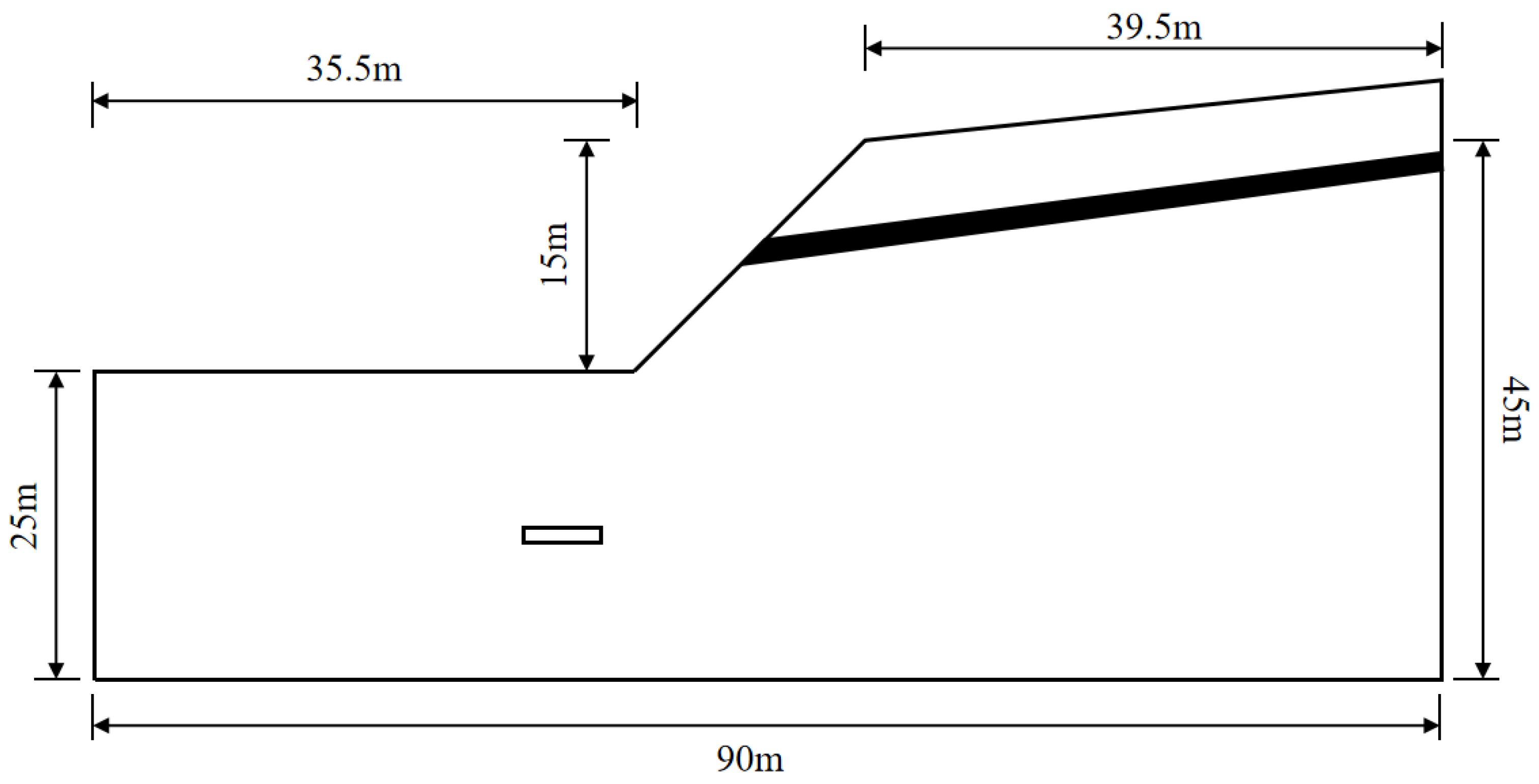
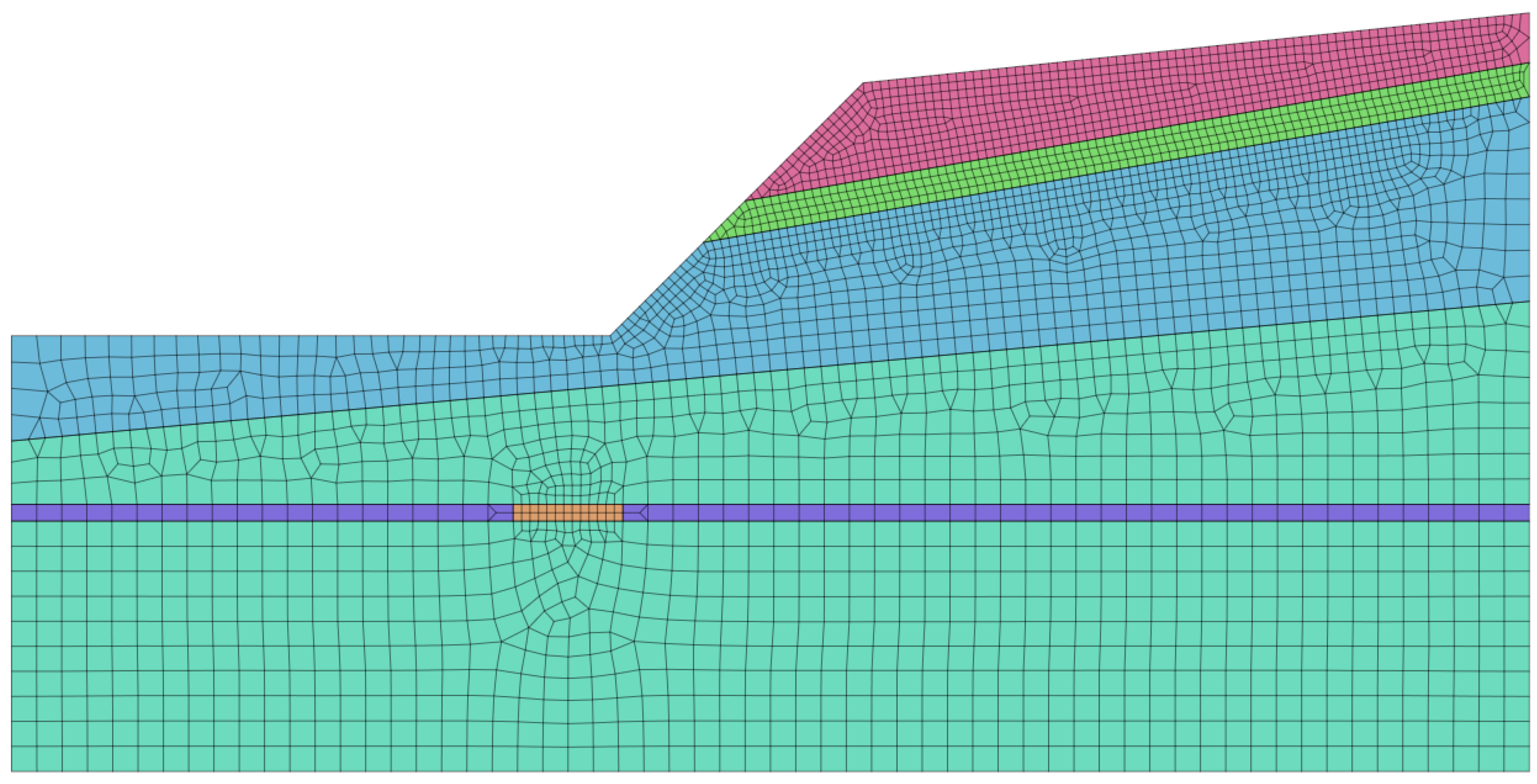
Given the results of the slope model parameter analysis in Section 2.3, we established a finite element slope model. The model had a top length of 39.5 m, a bottom length of 35.5 m, a height of 15 m, an upper and lower boundary distance of 45 m, and a left and right boundary distance of 90 m, as shown in Figure 3. The model size accords with the reasonable slope finite element model size, advised by Zheng [27]. We regarded rock, soil, and coal seam as isotropic and locally homogeneous materials in the analysis and calculation, and we adopted the Mohr–Coulomb criterion as the constitutive model in the calculation. When dividing the grid, we divided the upper boundary of the slope, the slope surface, and the coal seam in 0.5 m unit lengths, the slope gradient to the left boundary by a 0.5–1.5 m linear gradient, the left, right, and bottom boundaries by 1.5 m unit lengths. The grid was dense to sparse from the slope to the model boundary, and the unit type was triangle + quadrilateral. The divided grid model is shown in Figure 4. We adopted normal constraints for the left and right boundaries, fixed constraints for the bottom boundary, and a free boundary for the top. We constrained the initial displacement, considered that the initial stress field was self-weighted, activated the self-weight during the analysis, and then set the calculation convergence criterion. Finally, we added the SRM working condition for the calculation. The acceleration due to gravity is 9.8 m/s2, and we set the convergence criterion of the calculation to terminate when the convergence error was less than 10−6 and the maximum number of iterations exceeded 1000.
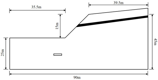
Figure 3.
Schematic diagram of the model size.

Figure 4.
Meshing of the finite element model.
According to the weather and the hydrological data in this area, we set the heavy rainfall condition as a rainfall of 200 mm in 24 h. According to the rainfall conditions, we applied the corresponding surface flow to the model. According to the project data and the initial groundwater level, we added node heads to the left and right boundaries of the model; we regarded the lower boundary as the impermeable boundary and the surface as the rain-permeable boundary.
3.2. Stability Analysis
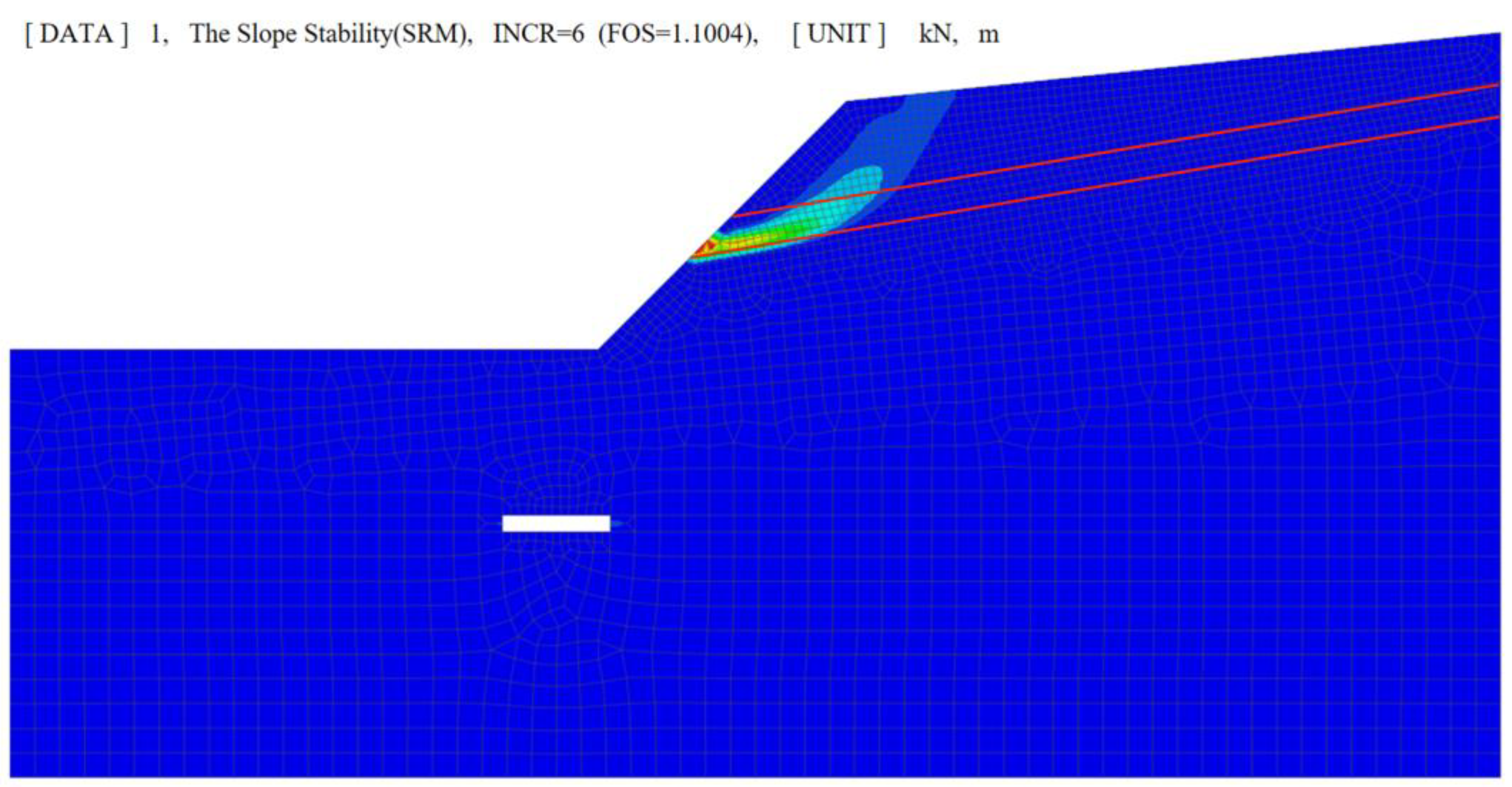
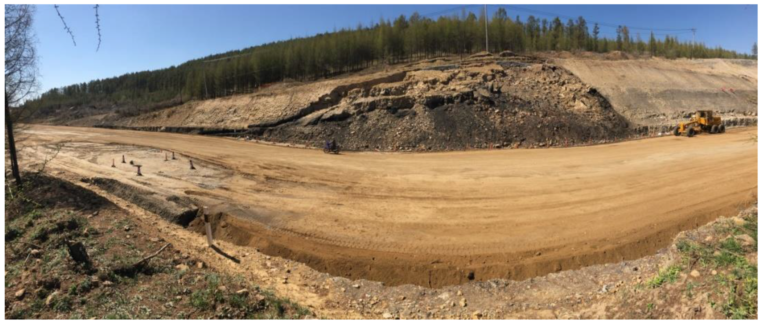
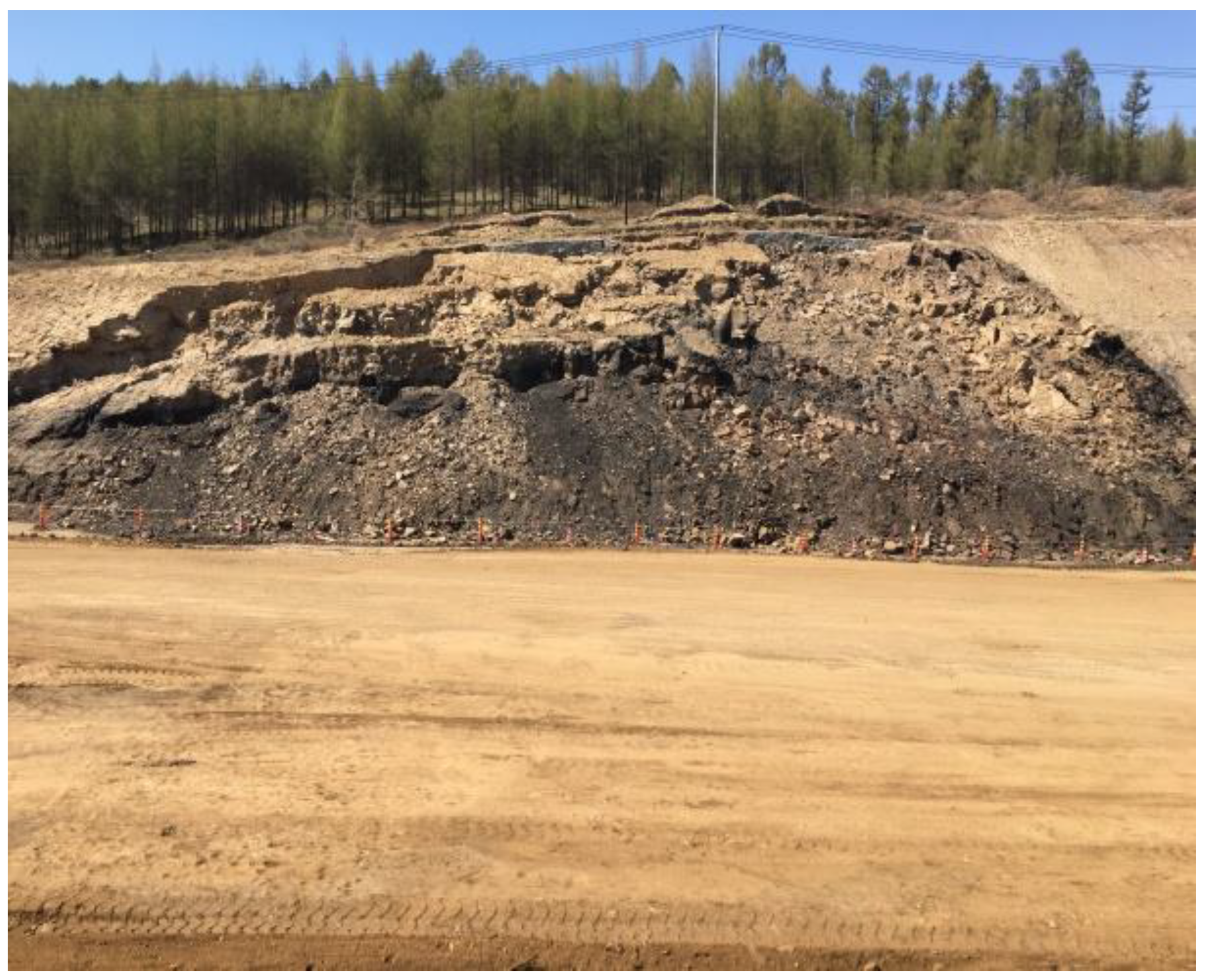
According to the requirements of The Code for Design of Highway Subgrade JTG D30-2015, the normal and rainfall working conditions should be considered in a slope stability analysis. Under normal and rainy conditions, the safety factor is 1.3 and 1.2, respectively [28]. We calculated the stability coefficient of the finite element model of the slope containing a coal seam in a goaf, established in Section 2.1. The calculation results under normal working conditions are shown in Figure 5. The overall actual situation of the slope instability and collapse, slope surface, and top of the slope is shown in Figure 6, Figure 7 and Figure 8, respectively.
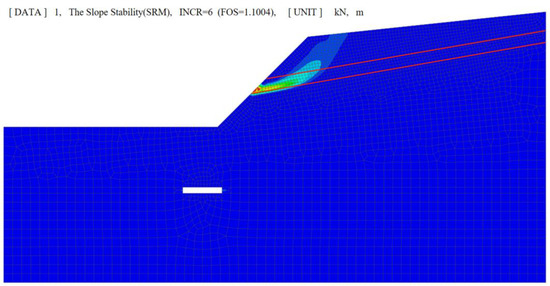
Figure 5.
Calculation stability of the slope containing a coal seam in a goaf. Within the scope of the red line is the position of the coal seam.

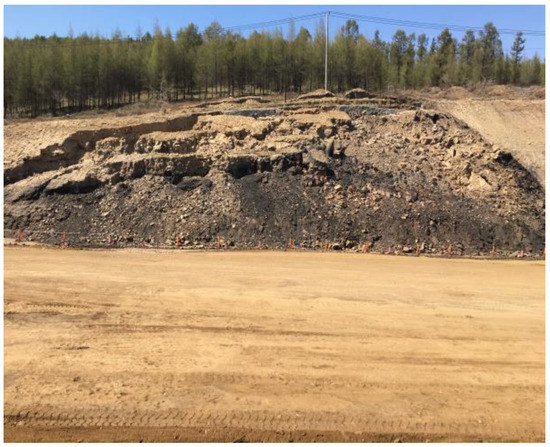
Figure 7.
Side view of the instability and collapse of a slope containing a coal seam in a goaf.

Figure 8.
Top view of the instability and collapsed top of a slope containing a coal seam in a goaf.
According to the calculated result of the slope stability in Figure 5, under the action of gravity, we found that the rock mass at the upper part of the coal seam of the slope had an outward sliding trend, and a potential sliding surface had formed in the coal seam. However, the calculated stability coefficient was 1.1. According to the requirements of the above specifications, the whole slope was in an unstable state. We performed the calculation again under the rainfall condition, obtaining a stability coefficient of 0.96, which indicated that the whole slope was in an unstable state, which would lead to a slump. No instability or collapse occurred in the actual cutting of the slope during excavation, but they did occur after rainfall. Then, only the upper part of the coal seam collapsed, the lower part of the coal seam remained intact, indicating that a sliding surface appeared in the coal seam, as shown in Figure 6, Figure 7 and Figure 8. We compared the simulation results with the actual engineering conditions, and the results are shown in Table 7. We found that the results, calculated by the simulation model, were consistent with the actual working conditions of the project, and the two mutually verified each other, which not only verified the accuracy of the calculation process of the simulation model but also explained the reasons for the collapse of the actual project. Under the rainfall condition, the stability coefficient was 0.96 < 1.
Table 7.
Comparison between the MIDAS GTS simulation and the actual working conditions.
4. Analysis of the Influencing Factors
4.1. Single-Factor Simulation
By consulting the data and referring to our engineering experience, we designed a single-factor simulation analysis. Table 8 shows the values of the coal seam position H, the roadway width W, the slope gradient i, the coal seam thickness T, the roadway position S, the mining depth and mining thickness ratio R, the coal seam cohesion c, the coal seam internal friction angle , and the coal seam inclination angle α. Taking the slope calculation model in Section 3.1 as the basic model, we analyzed the influence of the above single factors on the stability of the slope containing a coal seam in a goaf by changing the parameter, while the other factors remained unchanged. The analysis and calculation results are shown in Figure 8.
Table 8.
Single-factor value ranges.
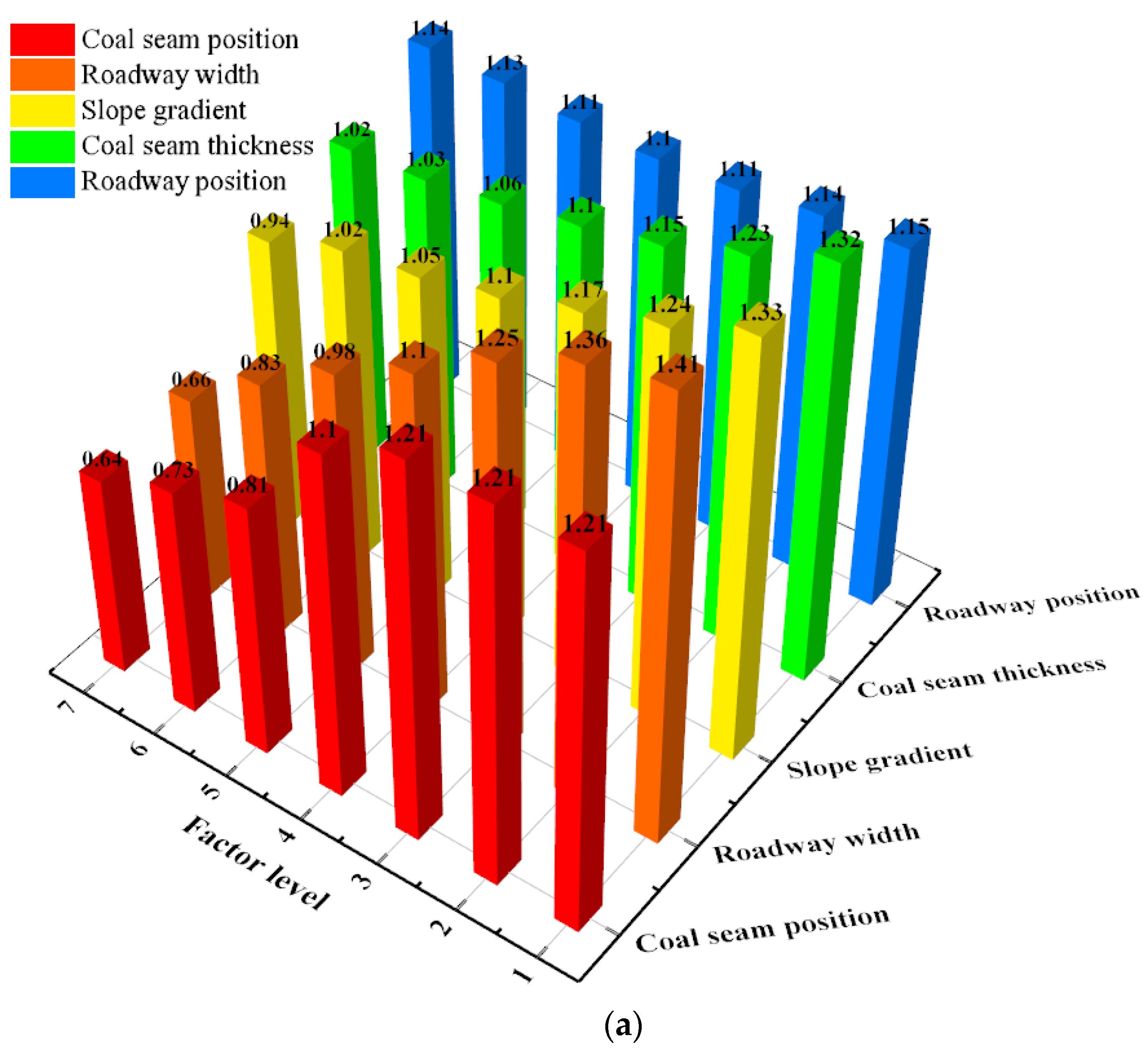
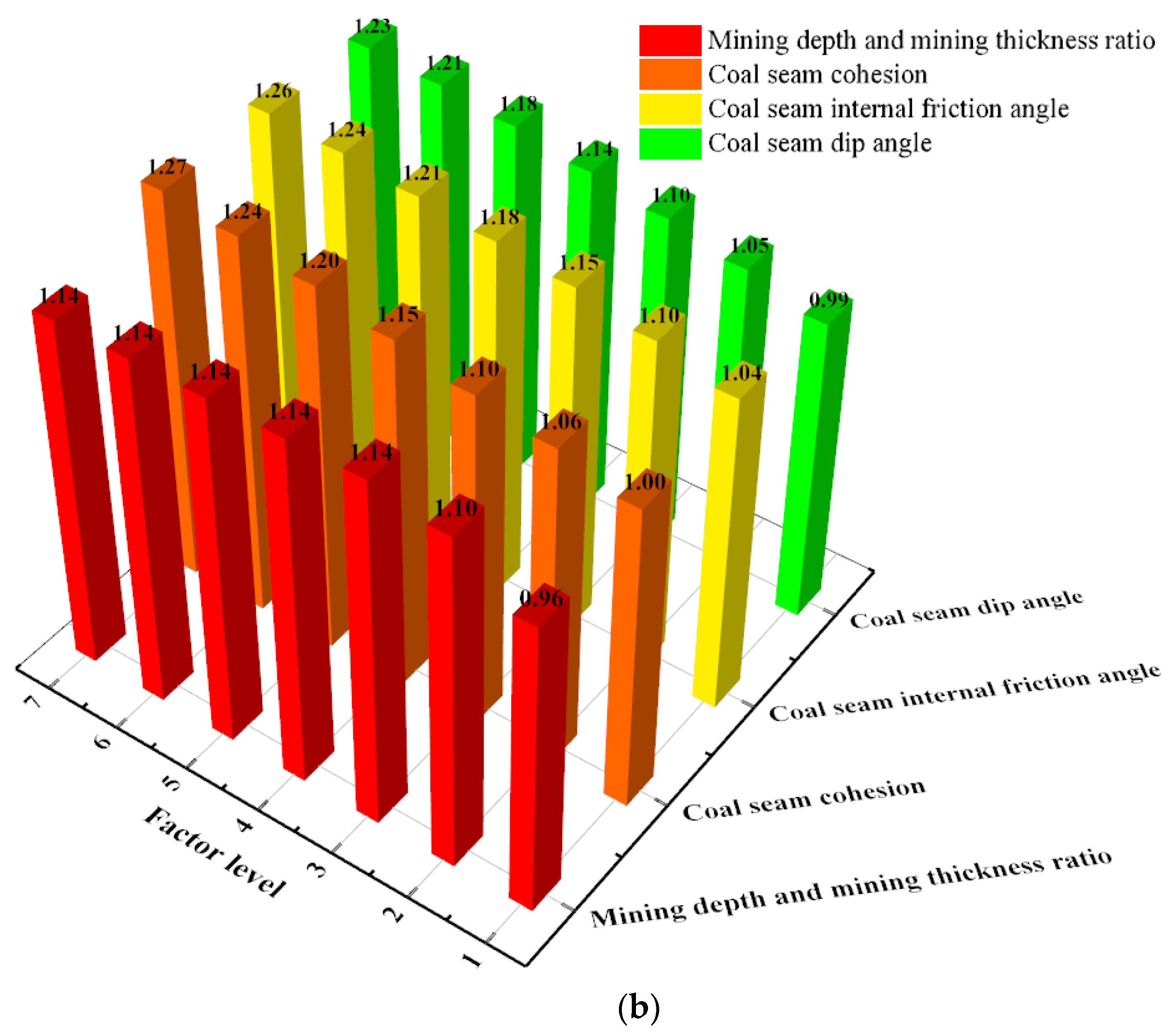
When other factors were kept the same, as in the basic model in Section 3.1, we found, as shown in Figure 9a, that when the coal seam position was changed, with the decrease in the coal seam position, the slope stability coefficient remained unchanged at first (2.5 < H < 5.5) and then sharply dropped (5.5 < H < 11.5). We found that with increasing roadway width, the slope stability coefficient gradually decreased. Changing the slope gradient, with the increase in the slope gradient, the slope stability coefficient gradually decreased. With the increase in the coal seam thickness, the slope stability coefficient gradually decreased. When changing the roadway position, with the horizontal distance from the slope foot changing from −15 to 15 m, the slope stability coefficient first decreased (−15 < S < 0) and then increased (0 < S < 15), which was almost symmetrical, but the change range was small, at less than 0.05. Figure 9b shows that with the increases in the mining depth and the mining thickness ratio, the slope stability coefficient first increased (5 < R < 15) and then remained unchanged (15 < R < 35); changing the cohesion of the coal seam, with the increase in the coal seam cohesion, the slope stability coefficient gradually increased. With the increase in the internal friction angle of the coal seam, the slope stability coefficient gradually increased. When the coal seam dip angle changed from −15°to 0°, the slope stability coefficient gradually increased.

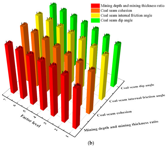
Figure 9.
Stability coefficient of a slope containing a coal seam in a goaf under different influencing factors. (a)influencing factors: the coal seam position, the roadway width, the slope gradient, the coal seam thickness and the roadway position; (b)influencing factors: the mining depth and mining thickness ratio, the coal seam cohesion, the coal seam internal friction angle and the coal seam dip angle.
From the above analysis results, we found that the coal seam position (between 5.5 m and 11.5 m), the roadway width, the slope gradient, and the coal seam thickness all adversely affected the slope stability, that is, the higher the values of the above four factors, the lower the slope stability coefficient. Additionally, the ratio of the mining depth to the mining thickness (5–15 m), the coal seam cohesion, the coal seam internal friction angle, and the coal seam dip angle favorably influenced the slope stability, that is, the higher the values of these four factors, the higher the stability coefficient of the slope. However, the roadway position had little influence on the stability of the slope, affecting the variation in the stability coefficient by less than 0.05.
According to the above analysis results, we eliminated one factor, the roadway position, which had little influence on the stability of the slope containing a coal seam in a goaf. We then designed the multifactor orthogonal experiments on the coal seam position (5.5–11.5 m), the roadway width, the slope gradient, the coal seam thickness, the coal seam cohesion, the mining depth and mining thickness ratio (5–15), the coal seam dip angle, and the coal seam internal friction angle, which showed a notable influence on the slope stability, to further determine the major and minor factors affecting the slope stability.
4.2. Orthogonal Multifactor Simulation Test
The orthogonal design is the most important method in a multifactor simulation experiment. This method is a multi-factor simulation test method [29] that is based on the fractional principle of factor design and uses an orthogonal table, derived from a combination theory to arrange and design simulation tests. Then, the results are statistically analyzed.
In this orthogonal design, we selected the eight influencing factors as the study objects, and each factor had three levels, as shown in Table 9. The factors refer to the items that affected the simulation test results, and the levels refer to the size and level of each factor in the simulation test process. According to the principle of orthogonal design, we used the L27(38) orthogonal table to arrange the orthogonal simulation test of eight factors and three levels, then we obtained the orthogonal design table of the parameter levels of each factor influencing the slope containing a coal seam in a goaf, as shown in Table 10. Table 10 shows that we obtained 27 groups of different levels of combinations of slope parameter factors, corresponding to 27 rows in the orthogonal table; that is, the number of simulation tests was 27. We calculated each simulation of the slope stability coefficient, according to a set of parameter levels in Table 3, and we recorded the calculated slope stability coefficient. The slope stability coefficients of the 27 different parameter level combinations obtained from the simulation are shown in the last column of Table 10.
Table 9.
Levels of the factors.
Table 10.
Orthogonal table of a horizontal combination of the L27(38) parameters and the calculated slope stability coefficients.
4.2.1. Range Analysis of the Slope Stability Coefficient
The purpose of the range analysis is to calculate the range of the R values of the simulation results, corresponding to each column and level in the orthogonal table using mathematical statistics. Because the R of a factor is defined as the difference between the maximum and minimum value of the factor, the relative influence of the factor on the slope stability could be judged, according to the value of R. A large R indicates that the factor has a strong relative influence, so is a relatively main influencing factor. A small R indicates that this factor has a relatively weak influence and is a relatively minor factor [30]. During the range analysis, the total value (Tij) of the simulation results at each level of each factor should be first calculated, and then the average value (Kij) of the simulation results at each level of each factor should be calculated, according to Formula (4). Finally, the R value (Rij) of each factor can be obtained by Formula (5).
According to the above formula and combined with the simulation results of the slope stability coefficient in Table 3, we calculated the R value of the slope stability, and the results are shown in Table 11.
Table 11.
Range analysis of the factors affecting slope stability.
According to the ranges listed in Table 11, the R values corresponding to the eight factors H, W, i, T, R, c, , and α were 1.21, 1.85, 0.83, 0.72, −0.05, −0.69, −0.71, and −0.57, respectively. The R values of the eight factors in descending order were RW > RH > Ri > RT > R > Rc > Rα > RR. That is, among the eight factors that impacted the slope stability that we analyzed, because the R value corresponding to W was the largest, we found that the change in the roadway width W had the strongest relative impact on the slope stability coefficient index. Ranked second was H, followed by i, T, , c, α, and R, indicating that the level change of the last had the weakest relative influence on the slope stability coefficient. Therefore, we found that the ranking of the relative influence of each factor on the slope containing a coal seam in a goaf was W > H > i > T > > c > α > R.
4.2.2. Variance Analysis of the Slope Stability Coefficient
The range analysis method could only be used to determine the relative influence of each factor on the slope stability coefficient, but could not be used to determine whether the influence of each factor on the slope stability coefficient was significant and the magnitude of the significance. The variance analysis, as a method of analyzing experimental data, can be used to study whether the influence of factors on the experimental results is significant. Therefore, through the analysis of variance on the slope stability coefficient, we investigated the significance of the influence of the eight factors H, W, i, T, R, c, and α on the slope stability coefficient.
According to the theory of the variance analysis of the orthogonal test and the data of the slope stability coefficient in Table 10, we calculated the mean square, degree of freedom, the sum of squares, and p value of each factor, where p < 0.05 indicated that the factor significantly influenced the slope stability coefficient. The results are shown in Table 12.
Table 12.
Variance analysis of the factors affecting slope stability.
Table 12 shows that among the eight factors analyzed, the corresponding P values of factors H, W, i, T, c, , and α were all less than 0.05, indicating that these seven factors significantly influenced the slope stability coefficient. The P value of factor R was 0.675 > 0.05, indicating that this factor had no significant influence. Combined with the differences in the F values, we further compared the significant differences among the seven factors that had a significant influence. Among them, the F value of the roadway width was 245.375, which was the most significant influence. This showed that reducing the roadway width can considerably improve the stability of a slope containing a coal seam in a goaf, during the implementation of practical projects. The F value of the coal seam position was 104.751, and its influence degree was second only to the roadway width. If the roadway width cannot be changed, the coal seam position plays a decisive role in the stability of the coal seam containing a slope in the goaf. The F value of the slope gradient was 50.375, ranking it third in terms of influence. Although its significance was less than that of the above two factors, the degree of significance was still highly significant, so the slope gradient also played a crucial role in the stability of the slope containing a coal seam. The F values of the coal seam thickness, coal seam internal friction angle, coal seam cohesion, and the coal seam dip angle were 36.522, 35.865, 34.298, and 23.259, respectively, ranking their influence as fourth to seventh, respectively. The significance of these four factors was relatively weak, and they had less influence on the stability of the slope containing a coal seam in a goaf than the above three factors.
From the above analysis, we found that, among the factors affecting the stability of the slope containing a coal seam in a goaf, the roadway width, the coal seam position, and the slope gradient were the main significant factors affecting the stability of the slope. This showed that grouting in goaf roadways, to reduce roadway width, cutting the top of the slope to control the coal seam position, and reducing the slope gradient can considerably improve the stability of slopes in actual projects. Although the coal seam thickness, the coal seam internal friction angle, the coal seam cohesion, and the coal seam dip angle are also significant factors influencing the slope stability, their degree of influence is less than that of the above three factors, so they are minor, but significant, factors influencing slope stability.
5. Discussion
The novelty of this study of the factors influencing the stability of a slope containing a coal seam in a goaf, studied in the coupled analysis of the influence of goaf roadways and coal seams on slope stability. Considering this special working condition, we analyzed the major and minor influencing factors, with the results providing a scientific basis for the analysis for the protection of this type of slope in goafs.
Our findings enrich the literature on goaf slope stability because the previous researchers mostly focused on the influence of goaf excavations on existing slopes. Studies were lacking on unexploited coal seams in a goaf exposed to the slope surface, due to excavation.
From the analysis results of the numerical simulation and the actual working conditions on site, the sliding surface of this type of slope is located near the coal seam. The roadway width, coal seam position, and slope gradient are the main influencing factors affecting the stability of this type of slope, but their influencing mechanisms are different. The influence mechanism of the roadway width: the collapse of the roadway roof causes the deformation of the upper slope, with the increase of roadway width, the deformation of the slope, caused by the collapse, also increases, and worsens the overall stability of the slope. The influence mechanism of the coal seam position: the contact part between the coal seam and the rock stratum is the rock stratum structural plane, and the upper rock stratum of the structural plane generates a down-sliding force along the structural plane under the action of gravity. The lower the coal seam position, the greater the down-sliding force at the upper part, and the worse the overall stability of the slope. The influence mechanism of the slope gradient is similar to that of the coal seam. The larger the slope gradient, the greater the down-sliding force generated by the upper part of the coal seam, and the worse the overall stability of the slope.
As mentioned above, our findings provide both a scientific basis for the protection of slopes containing coal seams in goafs and a reference for similar engineering construction projects. However, in this study, we considered only a practical project for a modeling analysis. In future work, similar simulation tests can be used with a larger number of samples to analyze the factors influencing the stability of this type of slope.
6. Conclusions
In this study, considering the cutting slope containing a coal seam that was excavated in the section K1641+890-K1641+950 of a reconstruction and extension project of the Jixi Section of the Dan-A National Highway, we analyzed the factors affecting the stability of the slope containing a coal seam in a goaf by a single-factor numerical simulation and orthogonal multifactor numerical simulation. Our main conclusions are as follows:
(1) From our engineering experience, we identified nine factors that may affect the stability of this type of slope, and we analyzed the proposed factors with a single-factor numerical simulation. The results showed that the factors that affected the stability of a slope containing a coal seam in a goaf were the coal seam position, the roadway width, the slope gradient, the coal seam thickness, the coal seam cohesion, the mining depth and mining thickness ratio, the coal seam dip angle, and the coal seam internal friction angle.
(2) We arranged the numerical simulation scheme of the influencing factors using an orthogonal design, and we analyzed the influence of each factor with range and variance analyses. The results showed that the roadway width, the coal seam position, and the slope gradient were the main significant factors influencing the slope stability; the coal seam thickness, coal seam internal friction angle, coal seam cohesion, and the coal seam dip angle were the minor significant influencing factors. The influences of the mining depth and mining thickness ratio were not significant.
(3) Because the roadway width, the coal seam position, and the slope gradient were the three main factors controlling the stability of the slope containing a coal seam in a goaf, when this type of slope is treated in practical engineering applications, the stability of this type of slope should be improved by grouting in the roadway to reduce the roadway width and cutting the top of the slope to control the coal seam position, and the slope gradient should be reduced.
Author Contributions
Conceptualization, C.H. and C.D.; methodology, C.H., F.Z., C.D. and J.G.; software, C.H., F.Z., C.D. and J.G.; validation, F.Z. and C.D.; formal analysis, C.H., F.Z., C.D. and J.G.; investigation, C.H., F.Z., C.D. and J.G.; resources, C.H., F.Z. and J.G.; data curation, F.Z. and C.D.; writing—original draft preparation, C.H. and F.Z.; writing—review and editing, F.Z. and C.D.; visualization, F.Z. and C.D.; supervision, C.H.; project administration, C.H.; funding acquisition, F.Z. and J.G. All authors have read and agreed to the published version of the manuscript.
Funding
This research was funded by the Science and Technology Project of the Department of Transportation of Heilongjiang Province (20210430).
Institutional Review Board Statement
Not applicable.
Informed Consent Statement
Not applicable.
Data Availability Statement
The data used to support the findings of this study are available from the corresponding author upon request.
Conflicts of Interest
The authors declare that there is no conflict of interest regarding the publication of this paper.
References
- Karrech, A.; Dong, X.; Elchalakani, M.; Basarir, H.; Shahin, M.A.; Regenauer-Lieb, K. Limit analysis for the seismic stability of three-dimensional rock slopes using the generalized Hoek-Brown criterion. Int. J. Min. Sci. Technol. 2022, 32, 237–245. [Google Scholar] [CrossRef]
- Kardani, N.; Zhou, A.N.; Nazem, M.; Shen, S.L. Improved prediction of slope stability using a hybrid stacking ensemble method based on finite element analysis and field data. J. Rock Mech. Geotech. Eng. 2021, 13, 188–201. [Google Scholar] [CrossRef]
- Bai, G.X.; Hou, Y.L.; Wan, B.F.; An, N.; Yan, Y.H.; Tang, Z.; Yan, M.C.; Zhang, Y.H.; Sun, D.Y. Performance Evaluation and Engineering Verification of Machine Learning Based Prediction Models for Slope Stability. Appl. Sci. 2022, 12, 7890. [Google Scholar] [CrossRef]
- Ijaz, N.; Ye, W.M.; Rehman, Z.U.; Dai, F.; Ijaz, Z. Numerical study on stability of lignosulphonate-based stabilized surficial layer of unsaturated expansive soil slope considering hydro-mechanical effect. Transp. Geotech. 2022, 32, 100697. [Google Scholar] [CrossRef]
- Yang, Q.; Li, R.J.; Zhang, S.B.; Li, R.J.; Bai, W.S.; Xiao, H.P. Algorithm Implementation of Equivalent Expansive Force in Strength Reduction FEM and Its Application in the Stability of Expansive Soil Slope. Water 2022, 14, 1540. [Google Scholar] [CrossRef]
- Zhou, J.F.; Qin, C.B. Stability analysis of unsaturated soil slopes under reservoir drawdown and rainfall conditions: Steady and transient state analysis. Comput. Geotech. 2022, 142, 104541. [Google Scholar] [CrossRef]
- Pi, X.Q.; Li, L.; Tang, G.P.; Zhang, R.; Zhao, L.H. Stability analysis for soil slopes with weak interlayers using the finite element upper bound limit analysis. J. Rail Way Sci. Eng. 2019, 16, 351–358. [Google Scholar]
- Korzec, A.; Jankowski, R. Extended Newmark method to assess stability of slope under bidirectional seismic loading. Soil Dyn. Earthq. Eng. 2021, 143, 106600. [Google Scholar] [CrossRef]
- Di, B.F.; Stamatopoulos, C.A.; Stamatopoulos, A.C.; Liu, E.N.; Balla, L. Proposal, application and partial validation of a simplified expression evaluating the stability of sandy slopes under rainfall conditions. Geomorphology 2021, 395, 107966. [Google Scholar] [CrossRef]
- Theocharis, A.I.; Zevgolis, I.E.; Deliveris, A.V.; Karametou, R.; Koukouzas, N.C. From Climate Conditions to the Numerical Slope Stability Analysis of Surface Coal Mines. Appl. Sci. 2022, 12, 1538. [Google Scholar] [CrossRef]
- Zhang, C.B.; Li, D.R.; Jiang, J.; Zhou, X.; Niu, X.Y.; Wei, Y.; Ma, J.J. Evaluating the potential slope plants using new method for soil reinforcement program. Catena 2019, 180, 346–354. [Google Scholar] [CrossRef]
- Liu, C.G.; Bi, H.J.; Wang, D.; Li, X.N. Stability Reinforcement of Slopes Using Vegetation Considering the Existence of Soft Rock. Appl. Sci. 2021, 11, 9228. [Google Scholar] [CrossRef]
- Ashpiz, E.S.; Lanis, A.L.; Razuvaev, D.A.; Lomov, P.O. Designing and Explanation of Reinforcement of Operated High Fills with the Injection of Solidifying Solutions. Transp. Res. Procedia 2022, 61, 614–620. [Google Scholar] [CrossRef]
- Sikora, P.; Wesołowski, M. Numerical assessment of the influence of former mining activities and plasticity of rock mass on deformations of terrain surface. Int. J. Min. Sci. Technol. 2021, 31, 209–214. [Google Scholar] [CrossRef]
- Xie, C.Y.; Hoang, N.; Bui, X.-N.; Van-Thieu, N.; Zhou, J. Predicting roof displacement of roadways in underground coal mines using adaptive neuro-fuzzy inference system optimized by various physics-based optimization algorithms. J. Rock Mech. Geotech. Eng. 2021, 13, 1452–1465. [Google Scholar] [CrossRef]
- He, J.S. Combined Application of Wide-Field Electromagnetic Method and Flow Field Fitting Method for High-Resolution Exploration: A Case Study of the Anjialing No. 1 Coal Mine. Engineering 2018, 4, 667–675. [Google Scholar] [CrossRef]
- Zhang, S.K.; Zhang, X.D.; Li, Y.J. Old goaf detection and verification techniques under highway. J. Cent. South Univ. Sci. Technol. 2015, 46, 3361–3367. [Google Scholar]
- Zhao, X.H.; Liu, C.Y.; Zuo, L.M.; Wang, L.; Zhu, Q.; Liu, Y.C.; Zhou, B.Y. Synthesis and characterization of fly ash geopolymer paste for goaf backfill: Reuse of soda residue. J. Clean. Prod. 2020, 260, 121045. [Google Scholar] [CrossRef]
- Yao, Y.C.; Yuan, B.Y. Study and Analysis of the Key Technology of High Speed Railway Subgrade in Complex Goaf. J. Railw. Eng. Soc. 2021, 38, 47–52. [Google Scholar]
- Wang, K.; Feng, G.R.; Bai, J.W.; Guo, J.; Shi, X.D.; Cui, B.Q.; Song, C. Dynamic behaviour and failure mechanism of coal subjected to coupled water-static-dynamic loads. Soil Dyn. Earthq. Eng. 2022, 153, 107084. [Google Scholar] [CrossRef]
- Orlecka-Sikora, B.; Lasocki, S.; Lizurek, G.; Rudzinski, L. Response of seismic activity in mines to the stress changes due to mining induced strong seismic events. Int. J. Rock Mech. Min. Sci. 2012, 53, 151–158. [Google Scholar] [CrossRef]
- Xie, L.K.; Xiong, D.Y.; Yang, T.H.; Wan, C.C.; Hu, J.J. Analysis and treatment of hidden goaf disaster under slope of open pit. Chin. J. Nonferrous. Met. 2020, 30, 2503–2512. [Google Scholar]
- Xu, M.B.; Xia, A.X. Numerical Simulation for the Influence of Goaf on the Slope Stability. Min. Res. Dev. 2016, 36, 50–54. [Google Scholar]
- Li, W.; Ren, P.; Li, Q.Y.; Guo, X.F. Study on instability mechanism of red clay slope under the influence of goaf. Saf. Coal Mines 2021, 52, 237–240. [Google Scholar]
- Zhao, B.; Zhao, Y.Q.; Wang, J.M.; Ren, Z.D.; Du, J.F. Goaf slope risk evaluation model based on improved TOPSIS method. J. Nat. Disasters 2020, 29, 164–171. [Google Scholar]
- Zhang, Y.J.; Chen, G.P.; Li, Q.L.; Sun, D.; Li, B.; Wan, Y. Study on Slope Instability Process under the Effect of Multistage Mining Activities. Met. Mine 2015, 10, 156–162. [Google Scholar]
- Zhang, L.Y.; Zheng, Y.R.; Zhao, S.Y.; Shi, W.M. Study on the accuracy of the finite element strength reduction coefficient method for calculating the safety factor of soil slope stability. J. Water Conserv. 2003, 01, 21–27. [Google Scholar]
- JTG-D30-2015; Code for Design of Highway Subgrade. People’s Communications Publishing Press: Beijing, China, 2015.
- Yang, D. Experimental Design and Analysis; China Agricultural Publishing House: Beijing, China, 2002; p. 171. [Google Scholar]
- Ruggiero, A.; Tricarico, L.; Olabi, A.G.; Benyounis, K.Y. Weld-bead profile and costs optimisation of the CO2 dissimilar laser welding process of low carbon steel and austenitic steel AISI316. Opt. Laser Technol. 2011, 43, 82–90. [Google Scholar] [CrossRef]

Publisher’s Note: MDPI stays neutral with regard to jurisdictional claims in published maps and institutional affiliations. |
© 2022 by the authors. Licensee MDPI, Basel, Switzerland. This article is an open access article distributed under the terms and conditions of the Creative Commons Attribution (CC BY) license (https://creativecommons.org/licenses/by/4.0/).