Article

Numerical Investigation of Air Entrapment Dynamics for High-Speed Thermal Spraying

1
Ocean College, Zhejiang University, Zhoushan 316000, China
2
Southern Marine Science and Engineering Guangdong Laboratory, Guangzhou 510000, China
3
Yangjiang Offshore Wind Turbine Lab, Yangjiang 529500, China
4
Department of Physics, George Washington University, Washington, DC 20052, USA
5
Department of Mechanical and Aerospace Engineering, George Washington University, Washington, DC 20052, USA
*
Authors to whom correspondence should be addressed.
Appl. Sci. 2022, 12(23), 12039; https://doi.org/10.3390/app122312039
Submission received: 4 November 2022 / Revised: 15 November 2022 / Accepted: 23 November 2022 / Published: 24 November 2022

Abstract

:
For thermal spraying, bubble entrapments are highly undesired, as this would lead to pores in the final coating and lower its adhesion quality. This understanding warrants an investigation of the process behind their formation. Nevertheless, the air entrapment process is difficult to study via experimental methods since molten droplets are always opaque and hard to visualize. Most numerical models are focused on air entrapment at the moment of impact, which could only explain the pores observed around the center of the splat. Here, in this paper, the air entrapment of a micron-sized molten nickel droplet impacting on a stainless-steel substrate is numerically studied. The results show that, besides the air entrapped during the high-speed impacting (impacting air bubbles/IM bubbles), bubbles may also be entrapped due to the fallback of the pointed-out finger on the edge during the spreading process (spreading air bubbles/SP bubbles). The number and size of the entrapped SP bubbles are related to the solidification rate and spreading rate. Therefore, both low (50 m/s) and high (200 m/s) impacting speeds could achieve an entrapped bubble ratio that is about 10% lower than that of a medium one (100 m/s). However, the formed coating is thick for low impacting speeds, and the low entrapped bubble ratio is obtained due to the cut-off of the peripherical fingers, which is actually unwanted.

1. Introduction

Droplet impacts on an impermeable surface is a common phenomenon and used in many applications, such as pesticide spraying, spray coating, and inkjet printing. After the liquid droplet impacts the solid surface, it may spread, splash, break up, recoil, or even rebound, depending on the initial impacting conditions [1], the characteristics of the droplet [2], and the substrate [3,4]. Interestingly, air entrapment can always be discovered, no matter how the droplet behaves, which could critically affect its spreading process and outcome [5]. For thermal spray applications, entrapped air is particularly undesired, as this would leave pores in the coating and significantly lower the quality of the splat-substrate adhesion [6].
Air entrapment was first discovered by Chandra and Avedisian [7] during their experiment of an n-heptane droplet impacting on a stainless-steel surface. Since then, air entrapments have been widely studied, both experimentally [8,9,10] and numerically [11,12,13]. Studies on the air entrapment dynamics during thermal spraying are even harder, as the molten droplets are mostly metals and ceramics, which are opaque, making them impossible to directly observe through conventional instruments. Kamnis [14] found many of nanopores under the nickel splat after it impacts the copper substrate with a velocity of 65 m/s, and attributed these pores to the nucleation of gas bubbles during rapid postimpact depressurization. Shukla [15] observed the air retention in the center of a molten molybdenum droplet impacts on an aluminum substrate, and proposed that the initial contact of the molten droplet with the substrate is not a point but an annular area. Moreover, the phase transition of the molten droplet makes the theoretical model much more complicated and brings challenges to the numerical studies. There have been continual numerical modeling efforts to investigate this problem. Mehdi-Nejad [16] observed the formation of a bubble around the center in their modeling of a molten nickel droplet impacting on a flat stainless-steel surface with a speed of 50 m/s. Shukla [15] attributed their model’s sudden temperature drop at the droplet/substrate surface to air entrapment. Xiong [17] developed a model by 3D Lattice Boltzmann method to investigate the air entrapment of a molten droplet impacting and solidifying on a cold smooth substrate. Depending on the contact angle of the substrate, bubbles would either be entrapped as a single air bubble or as multiple isolated bubbles. Shukla et al. [18] simulated the dynamics of air entrapment of a molten molybdenum droplet impacting on a flat aluminum substrate by volume of fluid (VOF) method and showed that wall heat flux had a strong relation to the dynamic features of the entrapped air film. However, these reported numerical models mainly focus on the air layer entrapped just after the molten droplet impacts the substrate, which resembles the water droplet impaction and could only explain the observed globular pores around the impact center of the finally solidified splat. However, according to the characterization of the plasma-sprayed Zirconia coating [19], pores could be found around the center and the splat periphery. Tabbara [20] once discovered air entrapment at the moving front of a millimeter-sized tin particle landing on a flat stainless-steel surface with high impacting speeds of 100 m/s and 400 m/s in their model, but the entrapped bubbles are forced outwards during the spreading process. Zhang [21] also observed air entrapment along the interface during their simulations of a molten nickel droplet impacting on a stainless-steel substrate, but ascribed the bubble formation to the gas supersaturation inside the molten droplet without any further analysis. The reason for the air entrapment near the edge of the splat is still unclear.
In this paper, the dynamics of the air entrapment process of a molten nickel droplet impacting on a cold smooth stainless-steel substrate is investigated. Then, the influences of impacting velocity on the air entrapment are discussed.

2. Numerical Model

Since the molten droplet is spherical, an axis-symmetric model was used [15], as shown in Figure 1. A molten metal droplet with radius R and initial temperature Td0 impacted on a cold smooth substrate (L × H2, Ts0) with an initial velocity v and air as its surroundings (L × H1, T0 = 293.15 K). The substrate surface was set as a wetted wall with a constant contact angle θ. Surface roughness was neglected here.
The fluid was treated as a Newtonian incompressible laminar flow and solved by the Navier–Stokes equation and the continuity equation, as shown in Equation (1),
ρ v t + ρ · v v = p + μ 2 v + ρ g + F vol S v ,       ρ v = 0    
ρ and μ are the density and dynamic viscosity of the fluid, g is the gravitational acceleration, Fvol is the volumetric force and mainly refers to the surface tension force at the droplet–air interface. The source term Sv accounts for the Darcy effect of the mushy zone, which is treated as a porous medium and used to describe the mixed liquid–solid region during solidification (Tm − ∆TTTm + ∆T) [22]. This is written as follows
S v = C 1 α 2 α 3 + ε v
C = 105~109 is the mushy zone constant, ε is a small number (0.001) to avoid having a zero denominator [23], α is the liquid volume fraction and calculated based on the enthalpy-porosity method [24]. The liquid fraction is 0 for the solid phase (T < Tm − ∆T) and 1 (T > Tm + ∆T) for the liquid phase, as shown in Equation (3). When α = 0, this means the material in this cell is completely solidified and the velocity should drop to zero, which is accomplished by applying an extreme large source term to the momentum equation Equation (1).
α = 0 ,       T < T m α = T T m Δ T 2 Δ T ,         T m Δ T < T < T m + Δ T α = 1 ,           T > T m
The molten droplet–air interface is tracked by the Level-set method [22], and written as
ϕ t + · v ϕ = γ · ε l s ϕ ϕ 1 ϕ ϕ ϕ
γ is the reinitialization parameter, εls is the parameter controlling interface thickness, ϕ is the level-set function represented by a smeared Heaviside function here, which is 0 if filled with air, and 1 if filled with molten nickel.
Energy conservation combined with the enthalpy-transforming model was used to describe the heat transfer, as shown in Equation (5),
ρ C p T t + ρ C p v · T + · k T Q = 0
Cp is the heat capacity at constant pressure, k is the thermal conductivity, Q is the heat source. The total enthalpy in the droplet consists of sensible heat, which is due to the heat transfer either by heat conduction or convection, and latent heat, which is caused by phase change. Accordingly, a temperature-dependent heat capacity Cp is used for this description, as shown in Equation (6).
C p = 1 ρ α ρ l C p l + 1 α ρ s C p s + L α T
L is the latent heat, and the subscripts “s” and “l” represent solid and liquid, respectively. The density and thermal conductivity all evaluated by the average of the solidus phase and the liquidus phase, i.e., ρ = αρl + (1 − α)ρs, k = αkl + (1 − α) ks. Here, Q = 0, as there is no external heat source.

3. Model Validation

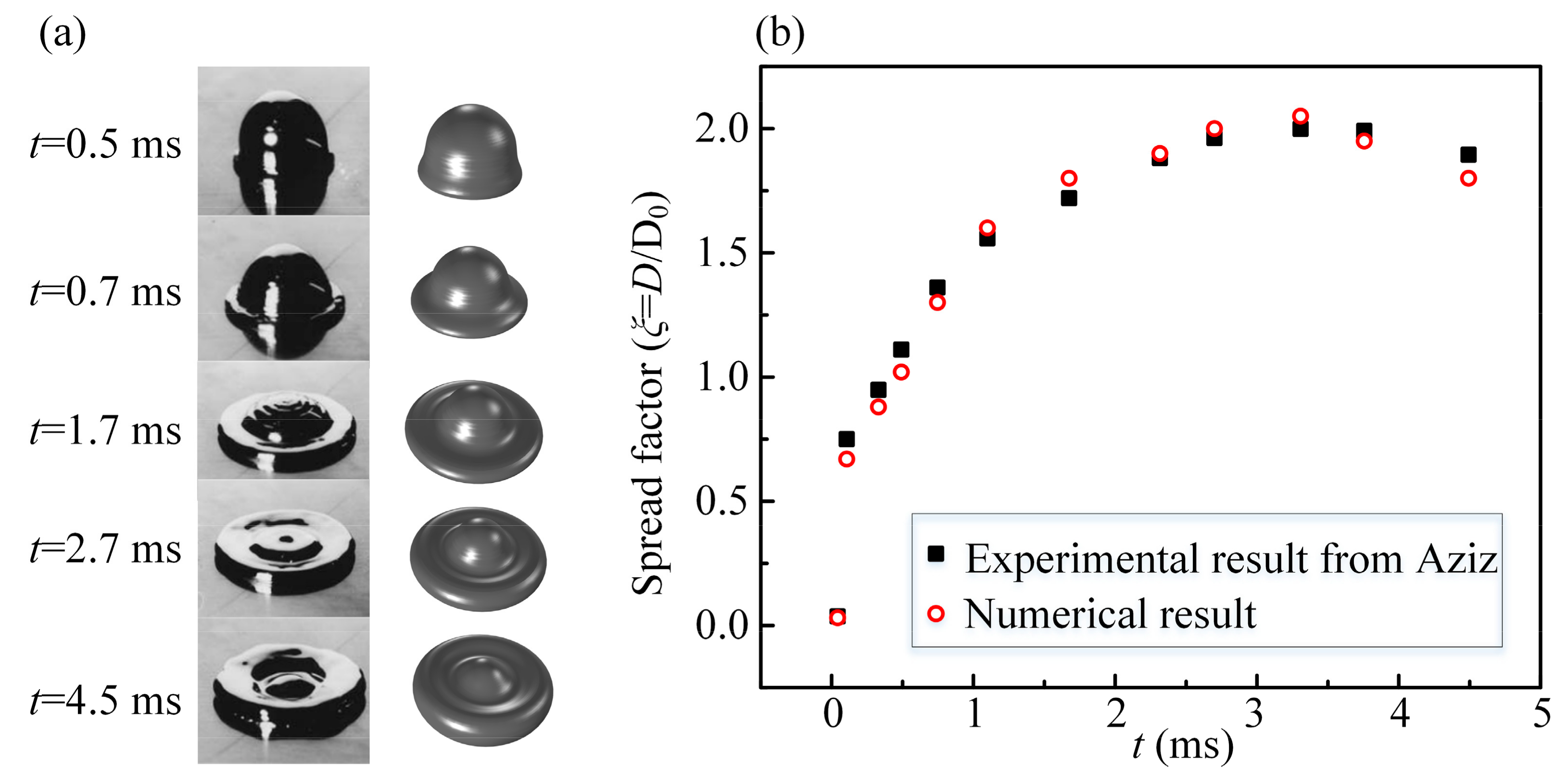
To verify this model, a comparison with the experimental results of Aziz [25] is made. The droplet is a molten tin droplet with Td0 = 509.15 K, R = 1.3 mm, Tm = 456.15 K. It impacts on a stainless-steel substrate (Ts0 = 298.15 K, θ = 140°) with an initial speed of v0 = 1 m/s. As shown in Figure 2a,b, both the evolution of the impaction and the spreading factor are consistent.

4. Results and Discussion

This model was applied to simulate a molten nickel droplet (d0 = 54 μm, h0 = 3 μm, Td0 = 2100 K) impacting on a stainless-steel substrate (L × H2 = 160 μm × 25 μm, Ts0 = 293.15 K) with an initial velocity v and air surroundings (L × H1 = 160 μm × 90 μm, T0 = 293.15 K). Their physical properties are listed in Table 1.
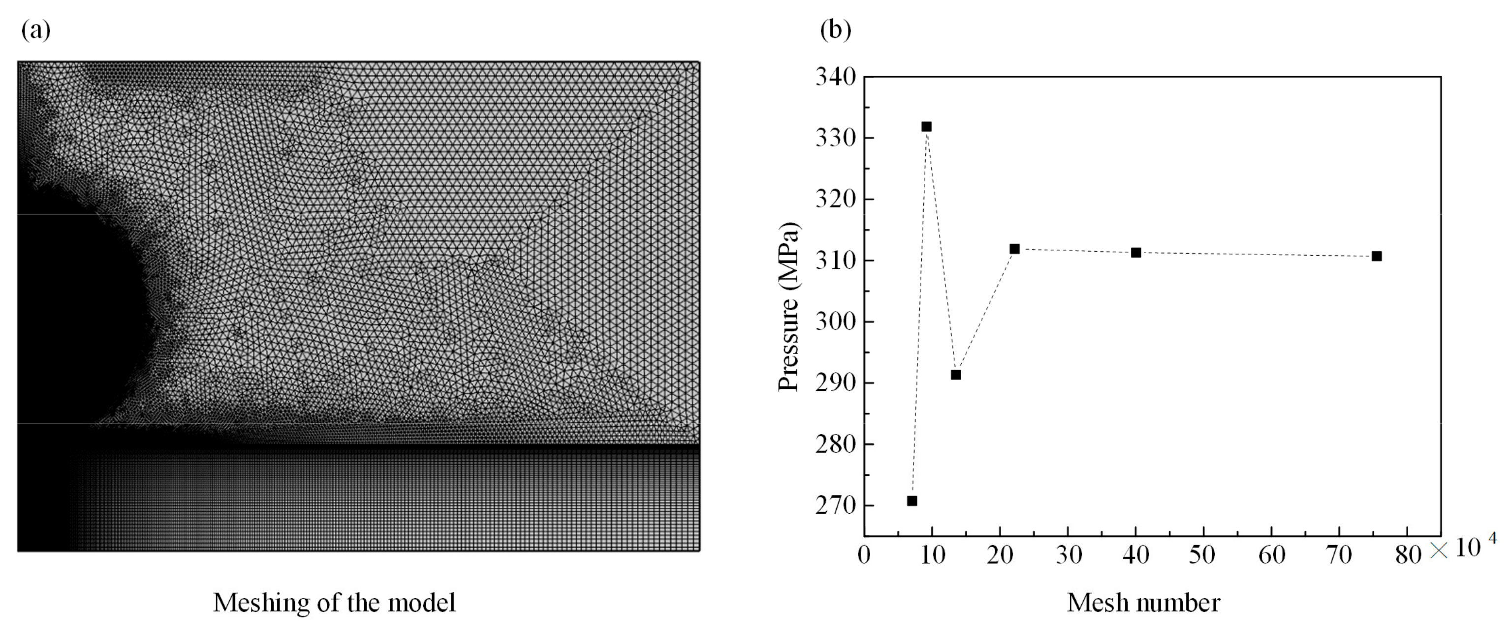
Triangular and mapped mesh were used, and the domains of the droplet and the contact area with the substrate were refined, as shown in Figure 3a. A mesh independence test was performed by checking the pressure at the point (1,1) at t = 0.1 μs. As shown in Figure 3b, when the mesh number is larger than 221,651, the mesh independence could be achieved, and this mesh is used for the following simulation.
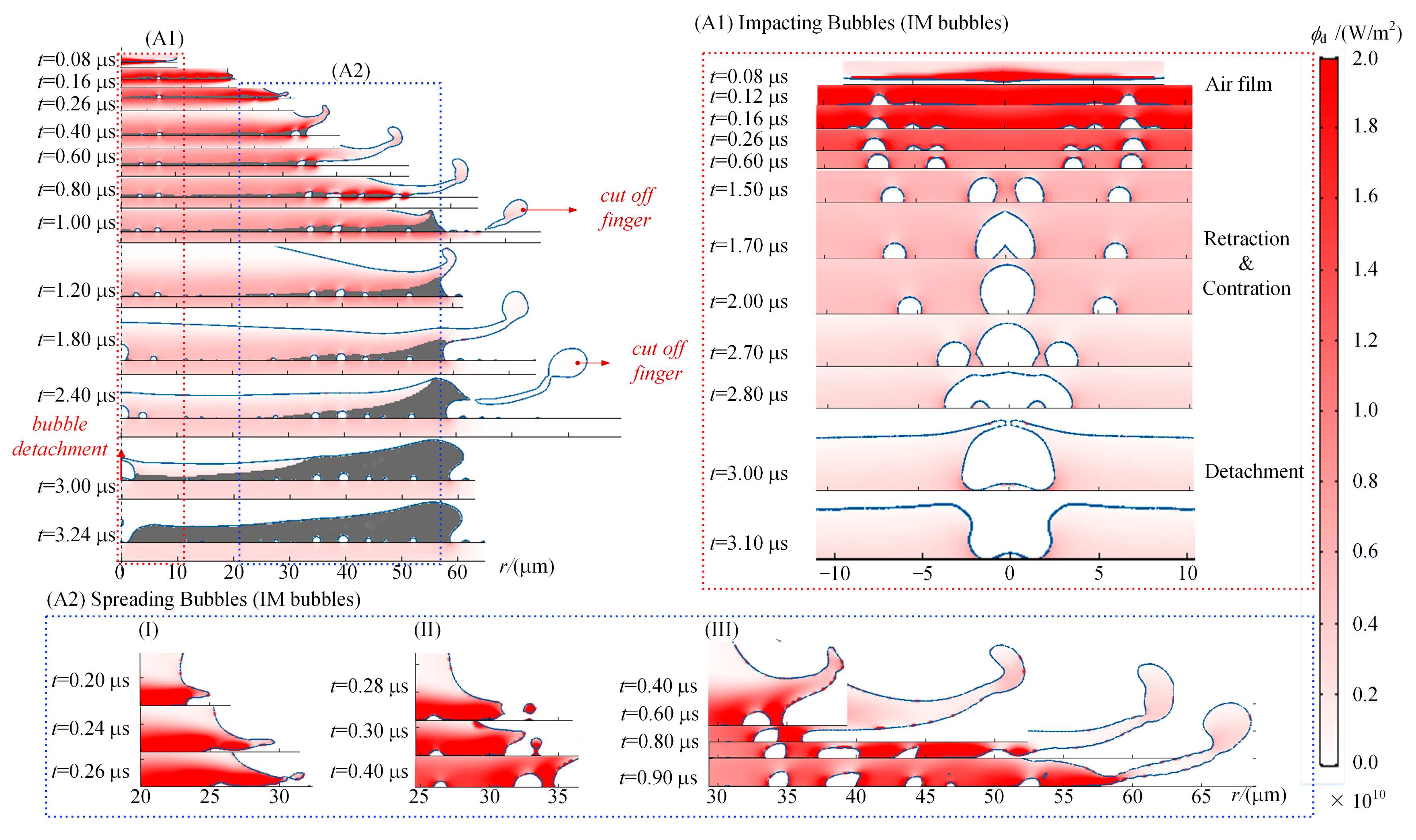
In general, the entrapped air bubbles during the whole process could be divided into impacting air bubbles (IM bubbles) and spreading air bubbles (SP bubbles) (Figure 4). The former results from the instant impact and the latter is entrapped due to the inhomogeneous solidification of the molten droplet. IM bubbles universally exist for impacting droplets either with [25] or without phase transition [5]. As shown in Figure 4A1, an air film with ripples is entrapped just after the droplet impacts the substrate (t = 0.12 μs) due to the capillary waves generated by the energy of the impaction [5]. The propagation speed of the wave could be estimated by 1.5 (2πσ/ρλ)0.5 (λ is the capillary wave length, λ << d0/2) [26], which is much greater than the retraction speed −(σ/ρδ)0.5 (δ is the air film thickness) [10]. Consequently, capillary waves converge when the crests touch the substrate, dividing the air film into individual toroidal bubbles. Meanwhile, to minimize the surface tension, the IM bubbles retract towards the center (t = 0.16–2.8 μs) [5] and finally merge into a sizeable toroidal bubble (t = 3.0 μs). The formed toroidal bubble is finally detached from the substrate (t = 3.10 μs), leaving a void in the center of the splat after complete solidification; this was observed in both experiments [27] and previous numerical simulations [28].
In addition to the IM bubbles, as shown in Figure 4, more bubbles are entrapped during the spreading process. Solidification is gradually completed with the spreading propagating from the bottom, which directly contacts the substrate upwards and from the edge to the center. The splat edge is unstable during this process, and fingers could be formed, as shown in Figure 4, at t = 0.16 μs, 0.26 μs, 0.40 μs, 1.20 μs. The fingers will either fall back to the substrate, entrapping air, or be cut off as secondary droplets (t = 1.0 μs, 2.4 μs). These air bubbles that are newly entrapped during the spread of the molten droplet along the substrate surface are named SP bubbles. As shown in Figure 4A2, in Figure 4(A2-I), the pointed-out finger falls back to the substrate, entrapping a small bubble on edge. In Figure 4(A2-II), the finger just touches the previously splashed secondary droplet, leading to a new bubble entrapment. Finally, in Figure 4(A2-III), a cluster of bubbles is entrapped due to a longer finger falling-back.
Unlike IM bubbles, SP bubbles are unique to molten droplets, which undergo phase transition during spreading. The formation of SP bubbles should be attributed to the inhomogeneous solidification of the droplet. Here, two kinds of heat transfer are involved, i.e., heat conduction via direct contact and heat convection via fluid movement. As shown in Figure 4, heat conduction occurs at the contact interfaces, including droplet/substrate interface, droplet/splat interface, and splat/substrate interface. While for heat convection, it refers to heat transfer during the movement of molecules within the fluids [29]. Accordingly, heat convection mainly occurs within the molten droplet’s liquid phase. As shown in Figure 5a, at t = 0.70 μs, the most severe heat convection occurs within the long pointed-out finger, while there is almost no heat convection within the mushy zone, and the corresponding velocity is zero (Figure 5b), indicating that the mushy zone mainly consists of solidified splat. Accordingly, the shear stress at the droplet/splat interface is large, restricting the further spread of the liquid part above the mushy zone. However, due to the non-zero dynamic energy, it continues to spread along the radial direction, and finally falls back to the substrate with new air entrapped. In contrast, at t = 0.90 μs, the liquid part above is not continuous, and a half-solidified cutting point is formed. This contracts due to the surface tension, creating a wedge-shaped rim with a height of 4 μm and bringing the cut-off of the finger. Consequently, the inhomogeneous solidification is the key to the behavior of the pointed-out finger: either falling back to the substrate with newly entrapped SP bubbles, or breaking up as secondary droplet.
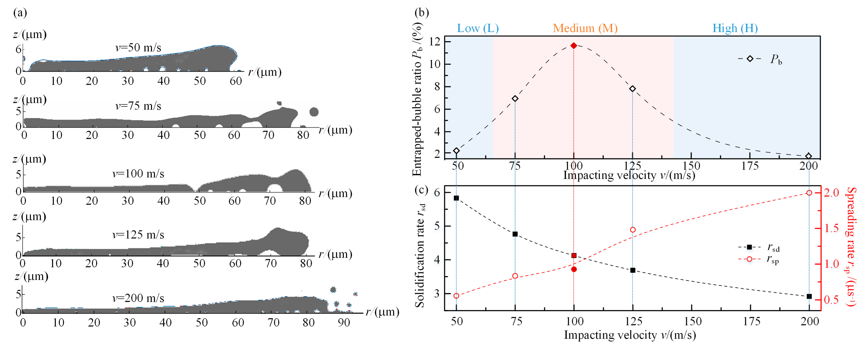
It is known that for a droplet without phase transition, the Ohnesorge number is used to describe its spreading dynamics after impact by comparing viscous forces with inertial and surface tension forces, Oh = μ/(ρd0σ)0.5 = (We)0.5/Re, where We = ρv2d0/σ, Re = ρvd0/μ. We reflect the driving force for the spreading, and Oh reflects the resistance. For this case, d0 = 54 μm, v= 50 m/s, Oh = 0.071 and We = 634.58. With a high We (We > 1) and low Oh (Oh < 1), it is impact-driven [26] and inertia-resisted, i.e., the impact speed has a great influence on its behavior. For plasma spraying, the particles are dozens of microns and will be accelerated to an even higher speed of about several hundred meters per second [30]. Omitting solidification, the impacting speed greatly affects the spreading and, thus, the SP bubbles’ entrapment. Considering solidification, as shown in Figure 4 and Figure 5, the SP bubbles’ entrapment depends on both the spreading and the freezing processes. Therefore, the air entrapments under different impacting speeds are investigated, and the results are shown in Figure 6a.
For a low impacting velocity (v = 50 m/s), the formed splat was thick and there were several small bubbles near the edge, together with a large center pore. For a medium impacting velocity (v = 75 m/s, 100 m/s and 125 m/s), larger entrapped SP bubbles could be detected due to the extended finger’s fallback on edge. Lastly, for a high impacting velocity (v = 200 m/s), the thinner splat made the finger land quickly back onto the substrate without any large bubble entrapments on the edge. The entrapped bubble size of v = 100 m/s was the largest, with a diameter of about 3.5 μm.
The entrapped-bubble ratio Pb = Vb/Vsp= (Vi + Vs)/Vsp is introduced here to evaluate the entrapped bubbles. Vb is the total volume of the entrapped bubbles, including IM bubbles, Vi, and SP bubbles, Vs, Vsp is the volume of the final formed intact splat. The result is shown in Figure 6b. Both low (L) and high (H) zones could achieve a low entrapped-bubble ratio Pb, compared to the medium zone (M). As shown in Figure 6a, this difference is mainly attributed to the bubbles entrapped on the edge, i.e., the SP bubbles, which resulted from the fallback of the pointed-out fingers. The behavior of the finger is decided by the competition of the solidification rate rsd and spreading rate rsp. The non-dimensional solidification rsd rate could be expressed by Equation (6) [31]:
r s d = 2 R e J a P r k s k l
Ja = Cp(TmTsub)/Lm is the Jakob number, where Tsub is the temperature of the substrate, Lm is the latent heat of fusion; Pr is the Prandtl number, Pr = μ/ραl, where αl is the thermal diffusivity of the melt; kl and ks are the thermal conductivity of the melt and solid, respectively. The spreading rate could be expressed as the reciprocal of the time when the melt has reached its maximum spreading radius Rmax, rsp = 1/tRmax. As shown in Figure 6c, with the increase in the impacting velocity v, rsd decreases, and rsp increases, i.e., the solidification proceeds more slowly and the spreading carries on more quickly. For Zone L, rsd is high; therefore, before the molten droplet spreads far away, the solidification has already completed, leading to a thick splat with high rims, cut off from the fingers. Since the splat’s fingers have been cut off, no extra bubbles are entrapped, resulting in a smaller Pb. On the contrary, for Zone H, spreading carries on more quickly than the solidification, so the molten droplet has enough time to spread further away, and a thinner splat could be obtained. The still-molten droplet causes the finger land smoothly back to the substrate, and the newly entrapped SP bubble will contract due to the surface tension on the bubble/melt interface. Thus, a much lower Pb could be achieved. For the M zone, the rsd and rsp are comparable, and the finger could still fall back to the substrate, even with a sharp rim on edge. However, the previous still-molten drople solidifies quickly after the bubble has been entrapped. Consequently, large SP bubbles are formed on the edge, resulting in a high Pb.

5. Conclusions

In this paper, the air entrapment of a molten nickel droplet impacting on a stainless-steel has been numerically investigated. Unlike the previous models, which mainly concerned the entrapped air around the center, in this paper, it is found that the entrapped air bubbles can be divided into impacting air bubbles (IM bubbles) and spreading air bubbles (SP) according to the stage at which they are entrapped. The pores found at the splat’s edge are attributed to the entrapped SP bubbles, which are related to the competition between the solidification rate rsd and spreading rate rsp. Moreover, the final bubble volume involved is related to the impacting velocity. For a low impacting speed (v = 50 m/s), even though a low entrapped-bubble ratio Pb could be obtained, the formed coating splat is thick and surrounded by cut-off fingers, which will negatively affect the subsequent molten droplet deposition. A medium impacting speed (v = 75 m/s–125 m/s) would result in a high entrapped-bubble ratio Pb, and large SP bubbles could be found on the edge of the splat. For a high impacting speed (v = 200 m/s), a relatively thin splat with small SP bubbles on edge is obtained. However, too high an impacting speed would cause serious splashing. To achieve an even coating with low porosity, a proper impacting speed should be carefully chosen according to the initial condition and physical characteristics of the material, which could affect the solidification rate or the spreading rate of the molten droplet, such as the temperature, the viscosity, thermal conductivity, etc.

Author Contributions

Conceptualization, H.G. and D.Y.; validation, K.W., J.C., R.Z. and M.L.; writing–original draft preparation, H.G., J.C. and R.Z.; writing–review and editing, D.Y. and M.L.; supervision, H.G.; funding acquisition, J.C. All authors have read and agreed to the published version of the manuscript.

Funding

This research was funded by 2020 Research Program of Sanya Yazhou Bay Science and Technology City, grant number SKYC-2020-01-001. Finance Science and Technology Project ofHainan Province, grant number ZDKJ202019. Key Special Project for Introduced Talents Team of South-ern Marine Science and Engineering Guangdong Laboratory (Guangzhou), grant number ML2019ZD0506. Key R&D Programmes of Guangdong, grant number 212021032611700002.

Institutional Review Board Statement

Not applicable.

Informed Consent Statement

Not applicable.

Data Availability Statement

Not applicable.

Acknowledgments

The authors acknowledge Xinyan Ma for technical assistance.

Conflicts of Interest

The authors declare no conflict of interest.

References

  1. Qin, Y.Z.; Guo, Q.Y.; Chen, R.X.; Zhuang, Y.; Wang, Y.L. Numerical investigation of water droplet impact on PEM fuel cell flow channel surface. Renew Energy 2021, 168, 750–763. [Google Scholar] [CrossRef]
  2. Almohammadi, H.; Amirfazli, A. Droplet impact: Viscosity and wettability effects on splashing. J. Colloid Interface Sci. 2019, 553, 22–30. [Google Scholar] [CrossRef] [PubMed]
  3. Andrzej, L.; Ariana, S.P.; Michelle, M.D.; Cacey, S.S.; Nagel, S.R. Creation of Prompt and Thin-Sheet Splashing by Varying Surface Roughness or Increasing Air Pressure. Phys. Rev. Lett. 2012, 109, 054501. [Google Scholar]
  4. Kenneth, R.L.; Alfonso, A.C.P.; Sigurdur, T.T. Droplet impacts onto soft solids entrap more air. Soft Matter 2020, 16, 5702–5710. [Google Scholar]
  5. Lee, J.S.; Weon, B.M.; Je, J.H.; Fezzaa, K. How does an air film evolve into a bubble during drop impact? Phys. Rev. Lett. 2012, 109, 204501. [Google Scholar] [CrossRef] [Green Version]
  6. Zhan, X.H.; Liu, Y.C.; Yi, P.; Feng, W.L.; Feng, Z.H.; Jin, Y.C. Effect of Substrate Surface Texture Shapes on the Adhesion of Plasma-Sprayed Ni-Based Coatings. J. Therm. Spray Technol 2020, 30, 270–284. [Google Scholar] [CrossRef]
  7. Chandra, S.; Avedisian, C.T. On the collision of a Droplet with a Solid Surface. Proc. R. Soc. Lond. A 1991, 432, 13–41. [Google Scholar] [CrossRef]
  8. Ruiter, J.D.; Oh, J.M.; Ende, D.V.D.; Mugele, F. Dynamics of Collapse of Air Films in Drop Impact. Phys. Rev. Lett. 2012, 108, 074505. [Google Scholar] [CrossRef] [PubMed] [Green Version]
  9. Ruiter, J.D.; Ende, D.V.D.; Mugele, F. Air cushioning in droplet impact. II. Experimental characterization of the air film evolution, Phys. Fluids 2015, 27, 12105. [Google Scholar]
  10. Thoroddsen, S.T.; Etoh, T.G.; Takehara, K.; Ootsuka, N.; Hatsuki, Y. The air bubble entrapped under a drop impacting on a solid surface. J. Fluid Mech. 2005, 545, 203–212. [Google Scholar] [CrossRef]
  11. Hicks, P.D.; Purvis, R. Air cushioning and bubble entrapment in three-dimensional droplet impacts. J. Fluid Mech. 2010, 649, 135–163. [Google Scholar] [CrossRef] [Green Version]
  12. Li, D.; Zhang, D.; Zheng, Z.W.; Tian, X.S. Numerical analysis on air entrapment during a droplet impacts on a dry flat surface. Int. J. Heat Mass Transf. 2017, 115, 186–193. [Google Scholar] [CrossRef]
  13. Yeganehdoust, F.; Attarzadeh, R.; Karimfazli, I.; Dolatabadi, A. A numerical analysis of air entrapment during droplet impact on an immiscible liquid film. Int. J. Multiph. Flow 2020, 124, 103175. [Google Scholar] [CrossRef]
  14. Qu, M.; Wu, Y.; Srinivasan, V.; Gouldstone, A. Observations of nanoporous foam arising from impact and rapid solidification of molten Ni droplets. Appl. Phys. Lett. 2007, 90, 254101. [Google Scholar] [CrossRef]
  15. Shukla, R.K.; Kumar, A. Substrate melting and re-solidification during impact of high-melting point droplet material. J. Therm. Spray Technol. 2015, 24, 1368–1376. [Google Scholar] [CrossRef]
  16. Mehdi-Nejad, V.; Mostaghimi, J.; Chandra, S. Air bubble entrapment under an impacting droplet. Phys. Fluids 2003, 15, 173–183. [Google Scholar] [CrossRef]
  17. Xiong, W.; Cheng, P. Numerical investigation of air entrapment in a molten droplet impacting and solidifying on a cold smooth substrate by 3D lattice Boltzmann method. Int. J. Heat Mass Transf. 2018, 124, 1262–1274. [Google Scholar] [CrossRef]
  18. Shukla, R.K.; Kumar, A.; Kumar, R.; Singh, D.; Kumar, A. Numerical study of pore formation in thermal spray coating process by investigating dynamics of air entrapment. Surf. Coat. Technol. 2019, 378, 124972. [Google Scholar] [CrossRef]
  19. Kulkarni, A.A.; Goland, A.; Herman, H.; Allen, A.J.; IIavsky, J.; Long, G.G.; Carlo, F.D. Advanced Microstructural Characterization of Plasma-Sprayed Zirconia Coating Over extended Length Scales. J. Therm. Spray Technol. 2005, 14, 239–250. [Google Scholar] [CrossRef]
  20. Tabbara, H.; Gu, S. Modelling of impingement phenomena for molten metallic droplets with low to high velocities. Int. J. Heat Mass Transf. 2012, 55, 2081–2086. [Google Scholar] [CrossRef]
  21. Zhang, Y.; Matthews, S.; Hyland, M. Role of solidification in the formation of plasma sprayed nickel splats through simulation and experimental observation. Int. J. Heat Mass Transf. 2017, 115, 488–501. [Google Scholar] [CrossRef]
  22. Ding, H.; Spelt, P.D.M. Inertial effects in droplet spreading: A comparison between diffuse-interface and level-set simulations. J. Fluid Mech. 2007, 576, 287–296. [Google Scholar] [CrossRef]
  23. Zheng, Y.Z.; Li, Q.; Zheng, Z.H.; Zhu, J.F.; Cao, P.L. Modeling the impact, flattening and solidification of a molten droplet on a solid substrate during plasma spraying. Appl. Surf. Sci. 2014, 317, 526–533. [Google Scholar] [CrossRef]
  24. Voller, V.R.; Prakash, C. A fixed grid numerical modelling methodology for convection-diffusion mushy region phase-change problems. Int. J. Heat Mass Transf. 1987, 30, 1709–1719. [Google Scholar] [CrossRef]
  25. Aziz, S.D.; Chandra, S. Impact, recoil and splashing of molten metal droplets. Int. J. Heat Mass Transf. 2000, 43, 2841–2857. [Google Scholar] [CrossRef]
  26. Schiaffno, S.; Sonin, A.A. Molten droplet deposition and solidification at low Weber numbers. Phys. Fluids 1997, 9, 3172–3187. [Google Scholar] [CrossRef]
  27. Tran, A.T.T.; Brossard, S.; Hyland, M.M.; James, B.J.; Munroe, P. Evidence of substrate melting of NiCr particles on stainless steel substrate by experimental observation and simulations. Plasma Chem. Plasma Process 2009, 29, 475–495. [Google Scholar] [CrossRef]
  28. Shukla, R.K.; Yadav, S.K.; Shete, M.H.; Kumar, A. Numerical modelling of impact and solidification of a molten alloy droplet on a substrate. In 5th International and 26th All India Manufacturing Technology, Design and Research Conference, Advances in Material Forming and Joining; Narayanan, R., Dixit, U., Eds.; Springer: New Delhi, India, 2014; pp. 307–322. [Google Scholar]
  29. Bi, Z.M. Finite Element Analysis Applications; Academic Press: Cambridge, MA, USA, 2019; pp. 341–377. [Google Scholar]
  30. Panwar, V.; Shweta, S.; Chawla, V.; Grover, N.K. A comprehensive review of thermal spray coating for coal fired power plants. Int. J. Mech. Eng. Technol. 2017, 8, 1208–1217. [Google Scholar]
  31. Zhang, H. Theoretical Analysis of Spreading and Solidification of Molten Droplet During Thermal Spray Deposition. Int. J. Heat Mass Transf. 1999, 42, 2499–2508. [Google Scholar] [CrossRef]
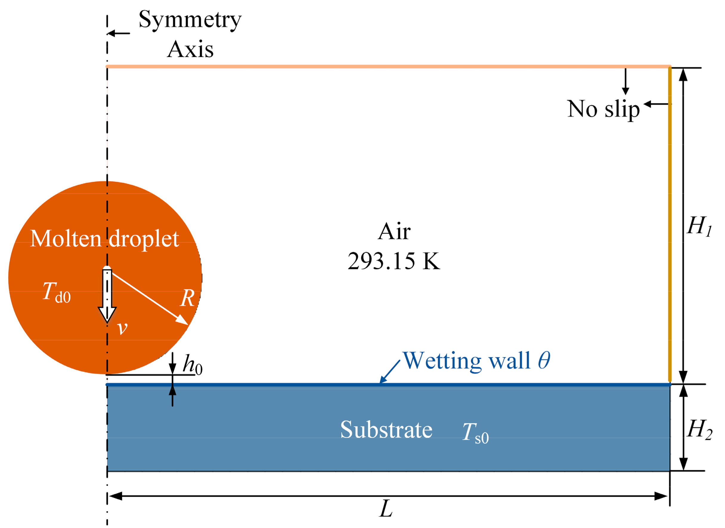
Figure 1. Schematic of the computation domain.
Applsci 12 12039 g001
Figure 2. Comparison with experimental results of Aziz [25]: (a) Evolution of the impacting process (Reprinted with permission from Ref. [25]. Copyright 2000 Elsevier) and (b) spreading factor.
Applsci 12 12039 g002
Figure 3. (a) Meshing of the model and (b) mesh independence check.
Applsci 12 12039 g003
Figure 4. Evolution of a molten nickel droplet’s solidification and air entrapment impacts a smooth stainless-steel substrate (room temperature T0 = 293.15 K) with an initial speed of 50 m/s. (A1) Detailed view of the impacting (IM) bubbles entrapping process. (A2) Detailed view of the spreading (SP) bubbles entrapping process: Entrapped by (I) falling back of fingers and (II) connecting with the splashed secondary droplet; (III) cluster of SP bubbles entrapment by falling back of a long finger. ϕd is the conductive heat flux. Applsci 12 12039 i001 represents the mushy zone of the molten droplet.
Applsci 12 12039 g004
Figure 5. (a) Convective heat flux ϕc and (b) velocity v & shear stress τ distribution of fall-back and cut-off splash, respectively. Applsci 12 12039 i002 represents the mushy zone.
Applsci 12 12039 g005
Figure 6. (a) Final entrapped bubbles and formed splat for different initial impacting speeds from low (v = 50 m/s) to high (v = 200 m/s), (b) entrapped-bubble ratio Pb, (c) solidification rate rsd and spreading rate rsp, with different initial impacting speeds: Low zone (L) (v = 50 m/s), medium zone (M) (v = 75 m/s, 100 m/s, 125 m/s) and high zone (H) (v = 200 m/s).
Applsci 12 12039 g006
Table 1. Physical properties of Ni and stainless steel (L: Liquid and S: Solid).
MaterialMelt Point
(K)
Density
(kg/m3)
Thermal Conductivity
(W/m∙K)
Specific Heat
(J/kg∙K)
Latent Heat
(kJ/kg)
Viscosity
(Pa∙s)
Surface Tension
(N/m)
Nickel17287850 (L)69.2 (L)735 (L)2920.006 (L)1.6 (L)
8450 (S)80 (S)595 (S)
Stainless-Steel1723785415480
Publisher’s Note: MDPI stays neutral with regard to jurisdictional claims in published maps and institutional affiliations.