1. Introduction
The composite nature of the roof of the roadway surrounding rock will determine the irregular nature of the failure form. When the composite roof contains a weak interlayer that is largely different from the neighboring strata in mechanical property, deformation failure unsynchronized with the neighboring strata will appear in this weak interlayer, potentially resulting in the overall failure of the roadway roof which eventually leads to support failure and even roof fall [
1,
2,
3,
4,
5]. Therefore, it is of great practical significance to reveal the mechanism of roofs in mining-disturbed roadways with soft and weak interlayers and to propose targeted control methods.
In practical engineering, the violent damage of the roof slab of the roadway with large deformation, resulting in the failure of support, is an important cause of the roadway roof and its destruction process is gradual. For the reasons of destabilization damage of the roadway, domestic and foreign scholars have conducted research, and the literature [
6,
7,
8,
9,
10] reveals the damage law of the very soft roof slab of the roadway with different roof coal thickness under the action of mining and gives the slurry anchor cable, with anchor cable reinforcement anchoring as the main countermeasures. The literature [
11,
12,
13,
14,
15] used the butterfly theory of the roadway envelope to draw the link between the damage pattern of the plastic zone of the roadway and the roofing and proposed the use of long anchor rods and anchor ropes to control the deformation of the envelope and achieved good results by field practice. The literature [
16,
17,
18] put forward the concept of support stress field and comprehensive stress field in order to better describe the role of anchor rod support, and the anchor rod In order to better describe the effect of anchor support, the concept of stress field and integrated stress field were proposed.
A large number of engineering practices have demonstrated the idiosyncratic nature of roof bulging in roadways with soft and weak interlayers. The literature [
19,
20,
21,
22] established a combined stress model for soft and weak interlayers to reveal the mechanism of damage in underground roadways, providing a basis for controlling the stability of the surrounding rock. The literature [
23,
24] used numerical simulations to derive the effect of soft and weak inclusions in the roadway floor on the roadway bottom drum under different stress field environments.
Many scholars have analyzed the damage mechanism and control methods of the surrounding rock of composite roof mining roadways from different perspectives, which is of great practical significance, but there are few studies that analyze the stability of the roof of the roadway around the distribution and expansion of the weak interlayer damage. The weak interlayer damage is the most sensitive to the impact of mining and is likely to determine the overall rupture pattern of the roof. Therefore, this paper takes a mine auxiliary roadway chute as the engineering background, and systematically studies the relationship between the distribution characteristics of the plastic zone of the mining roadway roof and the thickness of the underlying hard rock layer and the soft and weak interlayer, the distribution law of the plastic zone of the roof of the roadway with weak interlayer is obtained. According to its distribution characteristics, the optimization method of the surrounding rock control support of the mining roadway is proposed, and carries out a practical application in the field, in order to provide useful insights for the control of the surrounding rock of the mining roadway containing the soft and weak interlayer roof plate under similar geological conditions.
2. Background
2.1. Project Description
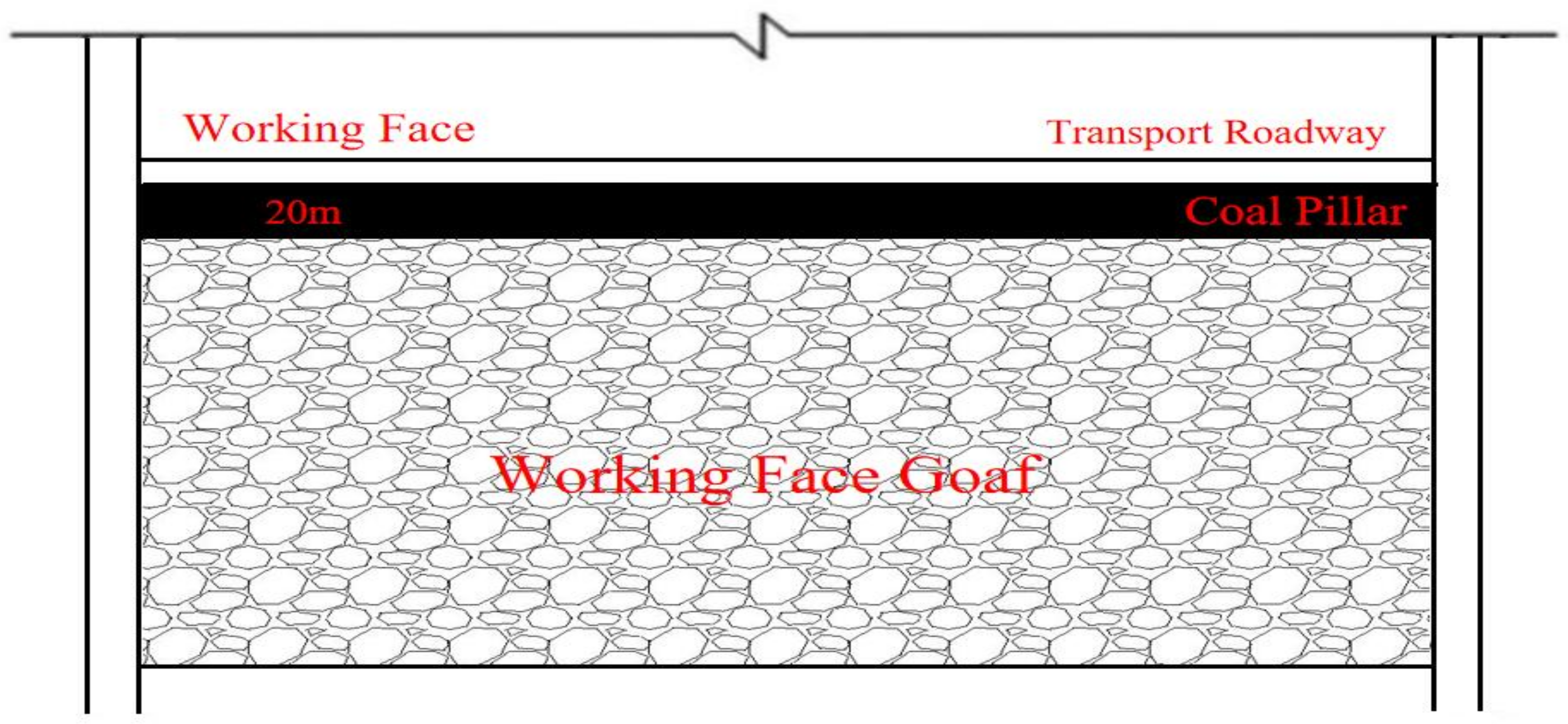
A mine’s comprehensive mining working face is located in a 22 coal 2 pan area, the average burial depth of the working face is 960 m. The main mining coal seam is 22 coal, the thickness of the coal seam is 1.8 m~4.6 m, the thickness of the coal seam varies greatly, and the dip angle of the coal seam is 1–3°. The working face is adjacent to the mining area via an auxiliary transport chute with a 20 m protective coal pillar. The site working face layout is shown in
Figure 1 and the geological column diagram of the coal and rock seam is shown in
Table 1. The roadway section shape is rectangular, the width is 4.5 m, the height is 2.6 m, the section area is 11.7 m
2, the roadway is dug along the bottom of the coal seam, and the physical parameters of the coal rock body on site are shown in
Table 2.
2.2. Force Environment and Deformation Characteristics of Roadway Surrounding Rock
The roadway used the original support scheme (Φ22 × L2000 mm equal-strength deformed steel resin bolts and W-tape biaxially stretched plastic meshes installed at the row and column spacing of 900 × 1000 mm; Φ21.8 mm × L4500 mm prestressed steel strand wire cables installed at the row and column spacing of 2100 × 3300 mm), which effectively controlled roadway surrounding rock deformation. The roof is more integral except for minor deformation and fracture at local points. The overall deformation was controllable. However, during the mining of the face, roadway deformation increased steeply. The section converged seriously. Part of the rock in the roof fell off; the wire meshes were broken; the steel tapes were badly damaged; all the bolts and cables were pulled out. In order to find out the cause, a borehole peeping was carried out on site. The results showed that the roof of the roadway was mainly composed of fine sandstone and coarse-grained sandstone, and there was a certain thickness of weak sandy mudstone layer with poor integrity at about 1.5 m above the roof of the roadway, and the wall of the peephole was rough and there were a lot of fissures. The deformation of the roadway is shown in
Figure 2. Note: Φ represents the diameter (mm); L represents the length (m).
From
Figure 2, it can be seen that one of the reasons for the large deformation of the local roadway is the presence of weak inclusions in the roof of the roadway. In order to verify the reasonableness of the 20 m wide coal pillar, a FLAC3D numerical calculation model was established based on the geological conditions. The model simulates the stability of the roadway envelope under the superposition of over-support pressure at the working face and lateral support pressure in the mining area. The side lengths of the numerical calculation model are x × y × z = 180 m × 150 m × 80 m, the working face mining length is 90 m (along the y direction), and the width is 110 m (along the x direction). The Mohr–Coulomb constitutive model was used, with displacement constraints applied around the model and at the base, and the roof surface of the model as a free boundary. The rock weight was taken as 25 KN/m
3. A vertical load of 22 MPa was calculated to simulate the overlying rock load on roof of the model, and the horizontal load was taken as 0.8 times the vertical load. The calculated stress distribution in the rock surrounding the roadway is shown in
Figure 3 and the support pressure is shown in
Figure 4.
From
Figure 4, the stress of the section pillar of the face is as high as 52.403 MPa and that of raw rock is 24 MPa, and the stress concentration coefficient can be calculated to be 2.4. Stress concentration mainly occurs in the coal pillar area. Under the lateral support pressure of the working face and the advanced support pressure, the plastic damage area of the coal body around the roadway is less, and there is no major deformation of the roadway. Moreover, the coal column did not occur complete plastic damage, and there is a certain elastic area, indicating that the coal column has sufficient bearing capacity, which is also one of the main reasons the roadway did not appear large deformation, so the site left a width of 20 m coal column, which is reasonable. However, the stress value of the coal rock body around the roadway increased under the influence of the mining area of the working face in the transport roadway, and according to
Figure 3, it can be judged that the stress value of the coal rock body around the roadway is between 30 MPa–35 MPa, and the closer to the coal column area, the higher the stress value. Through numerical simulation and field peeping, it can be judged that under the condition of the roadway being influenced by mining, the potential risk of roofing occurs mainly due to the soft and weak interlayer of the roadway roof.
3. Forces Acting on Roof Containing Weak Interlayer
After the roadway was excavated, the original stress state was broken. The stress was redistributed, changing from tridirectional to bidirectional [
25]. As the roadway was excavated, its surface became a free face with stress approximating 0 and began to bend under the self-weight stress. However, the strata of the roadway roof are generally layered with large lithological differences, and the deflection in different directions is different, too. When the inter-layer deflection difference is large or when there is a weak interlayer between the layers, the roof will begin to segregate. Based on this observation, a layered roof containing a weak interlayer is simplified as a composite rock beam to facilitate analysis. Assuming that the composite rock beam contains only one weak interlayer, a rock beam model for a layered roof containing a weak interlayer is established, as shown in
Figure 5.
In this model, the overall length, width, and height of the rock beam are l, b, and h. The thicknesses of the sublayers are h
1, h
2 and h
3 (h
1 + h
2 + h
3 = h). The elastic moduli of the sublayers are E
1, E
2, and E
3. Their moments of inertia are I
1, I
2, and I
3. According to the theory of mechanics, under uniformly distributed load q (without considering the effect of horizontal tectonic stress
σx), the maximum tensile stress
σtmax and maximum compressive stress
σcmax inside a layered rock beam are [
26]:
where
M is the maximum bending moment;
W is the bending section coefficient,
W = 1/6 kh
2, where h is the height of the composite beam and
k is the number of sublayers in the composite beam (in this model,
k = 3). Considering the influence of support at the ends, a conversion factor m is introduced and taken as follows:
① m = 1, fixed supported at the ends: the surrounding rock is well stable as a whole;
② m = 1/3, simply supported at the ends: the roof accommodates joints and fissures, the coal on the sides is soft;
③ m = 2/3, semi-fixed supported: the roof is moderately integral, the coal on the sides is relatively stable.
Using the conversion factor m, we obtain:
Now we have worked out the forces acting on the composite beam as a whole through the analysis above. However, to know the force distribution on individual layers, we have to first know how much bending moment the sublayers can withstand when the layered roof is under self-weight. According to the mechanics of materials:
where
L—span, m;
I—moment of inertia, m
4;
b—section width, which is the unit length;
P—radius of curvature, m;
E—elastic modulus, MPa. Before the composite beam becomes unstable under self-weight, the sublayers of a layered roof can still be regarded as a unity and their deformation curvature is the same, written as:
From the equation above, the bending moment on a sublayer is directly proportional to its stiffness EI. The bending moment of the roof under self-weight is the sum of the bending moments on all sublayers in the roof, written as:
Combining Equations (7)–(9) derives [
26]:
Substituting Equations (5) and (10) into Equation (1) derives the maximum tensile stress for a sublayer under bending moment as [
26]:
Substituting Equations (5) and (10) into Equation (2) derives the maximum compressive stress on a sublayer under bending moment as [
26]:
From Equations (11) and (12), the maximum tensile stress and maximum compressive stress on a sublayer are directly proportional to q, E, and l2. With all other conditions unchanged, the stress on the sublayers of an interbedded roof is primarily affected by E and h: a larger E corresponds to a larger σ; a smaller h corresponds to a larger σ. As a weak interlayer has very small h, the force on it is the largest. Additionally, as its strength is low, it is more likely to fail first.
4. Numerical Simulation
From the equations above, the stress on the sublayers of an interbedded roof is primarily affected by E and h: a larger E corresponds to a larger σ; a smaller h corresponds to a larger σ. In the reality of the shaft, the thickness of the weak interlayer is uneven, and under the influence of mining, the roof of the roadway is very vulnerable to damage, which may lead to the overall rupture of the roof. Therefore, further research is needed on the mechanism of destabilization of the roof of the roadway induced by changes in the thickness of the weak interlayer.
4.1. Numerical Modeling
According to the specific geological conditions of a mine working face (
Table 1), the finite element differential simulation software, FLAC3D, was selected to establish a numerical calculation model of the auxiliary transport chute of the working face, and the physical and mechanical parameters of the coal seam and each rock layer at the roof and bottom of the roadway in the model are shown in
Table 2.
To find out the influence of weak interlayer thickness and underlying hard strata thickness on roadway stability, a numerical test method is developed for weak interlayers and underlying hard strata of different thicknesses. Surrounding rock horizontal stress and plastic zone failure are used as the evaluation criteria.
Model mesh division: In the process of establishing the numerical calculation model, consider the model boundary effect and calculation speed, based on the characteristics of the FLAC3D 3D model: 1. the larger the model, the denser the meshing, accordingly the longer the calculation time; 2. when simulating the mining of a working face, the model calculation is slow, and it is hard to reach a balance; 3. to highlight the object of our study, the calculation model has to be meshed densely, with 0.25 m as a unit). The final determination of the numerical calculation model side length is x × y × z = 25 m × 20 m × 25 m and is combined with the actual rock structure situation for grid division. The model uses the Mohr–Coulomb constitutive model for the simulated coal rock mass, with displacement constraints applied all around the model and at the base, and a free boundary at the roof.
Application of vertical load to the model: the vertical load to the model is applied to simulate the state of stress to which the coal rock body would be subjected if undisturbed by excavation, i.e., the original rock stress. The vertical load values are usually obtained using calculations based on the formula (
), with the seam weight γ taken as 25 KN/m
3 and h is the depth of burial of the coal seam. However, through the above (
Figure 3 and
Figure 4) analysis, it can be seen that the stress value of the coal rock body around the roadway increases under the influence of the mining-disturbed area of the working face, and the stress value of the coal rock body around the roadway is between 30 MPa–35 MPa, and the closer to the coal pillar area, the higher the stress value. The literature [
10] also points out that there are many factors affecting the distribution of the mining superimposed stress field, but for deeply buried and moderately buried mines, due to the small size of the roadway section relative to the spatial dimensions formed by the working face, the stress redistribution caused by the working face at the location of the retrieved roadway can be roughly considered as the stress state around the retrieved roadway before the destruction of the surrounding rock. Therefore, instead of directly simulating the influence of face mining on roadway stability, a representative vertical and horizontal load is given by analyzing the mining stress environment at the roadway around the mining face (
Figure 3 and
Figure 4). Vertical load (32.5 MPa) and horizontal load (1.5 times the vertical load) are applied to the roof of the model to simulate the influence of working face mining on the roadway. The numerical model used for simulation is shown in
Figure 6.
4.2. Influence of Underlying Hard Strata Thickness on Roadway Surrounding Rock Stability
To identify how underlying hard strata thickness affects roadway surrounding rock stability, the internal connection between underlying hard strata thickness and overall roadway roof stability is numerically simulated under different underlying hard strata thicknesses (1 m, 1.5 m, 2 m), at a constant weak interlayer thickness of 0.6. The horizontal stress nephograms of the roadway surrounding rock are shown in
Figure 7.
From
Figure 7a–c, when the underlying hard strata thickness is 1 m, one single stress concentration zone appears above the roadway roof; the stress concentration reaches its maximum of approximately 51.62 MPa, primarily located at 3 m from the roadway roof (key layer 1). As the underlying hard strata thickness increases (1.5 m), two stress concentration zones appear; strata behavior is distinct in key layer 1; strata behavior seems to appear in the underlying hard strata; the maximum stress is 49.60 MPa, located at 2.5 m from the roadway roof (key layer 1). When the underlying hard strata thickness is 2 m, two distinct stress concentration zones appear above the roadway roof, primarily located near the key layers and the underlying hard strata; the maximum stress concentration zone has moved; strata behavior is distinct in the underlying hard strata, where the stress is as high as 49.68 MPa, located at 2 m from the roadway roof. The plastic zone distribution of the roadway surrounding rock is shown in
Figure 8.
By comparing
Figure 8a–c, when the underlying hard strata thickness is 1 m and 1.5 m, plastic failure occurs above the roadway roof (underlying hard strata, weak interlayer, and key layer 1) and the strata are interconnected. At the thickness of 1 m, the plastic failure in the weak layer gradually extends sideward and its width maximizes; the area of plastic failure in key layer 1 gradually reduces. At the thickness of 1.5 m, the sideward extension width of the plastic failure in the weak interlayer gradually reduces, and the area of plastic failure in key layer 1 gradually reduces. At the thickness of 2 m, plastic failure occurs above the roadway roof (underlying hard strata, weak interlayer), the plastic failure zones are not interconnected due to the influence of the underlying hard strata thickness, but the underlying hard strata thickness can protect key layer 1 from plastic failure. The width of the plastic failure in the weak interlayer further reduces; the roadway is primarily suffering shear failure. The horizontal stress distribution of the roadway surrounding rock is shown in
Figure 9.
From
Figure 9, as the distance from the roadway roof increases, the horizontal stress of the roadway surrounding rock first increases then reduces, then increases, then gradually reduces, and finally stabilizes. In the weak interlayer, the horizontal stress gradually reduces because (1) plastic failure in the rock of the weak interlayer leads to a stress reduction, and (2) the rock of the weak interlayer has low strength and loose structure; hence, low physical parameters (cohesion, internal angle of friction, elastic modulus). When the underlying hard strata thickness is 1 m and 1.5 m, strata behavior primarily occurs in key layer 1 because at these thicknesses, plastic failure occurs above the roadway roof (underlying hard strata, weak interlayer, and key layer 1) and the strata are interconnected, causing the stress to move away from the roadway roof. When the underlying hard strata thickness is 2 m, strata behavior primarily occurs in the underlying hard strata because at this thickness, the underlying hard strata do not fail completely, there are some elastic zones.
To sum up, it is suggested that:
Underlying hard strata thickness can determine the form of roof fracture. In a mining stress environment, obvious discontinuous failure occurs in the roadway roof containing a weak interlayer. The roof fracture zone shows obvious cross-layer propagation. The existence of more integral hard strata cannot prevent fracture zones from forming in the weak interlayer. Instead, fracture zones will redistribute in the less strong weak interlayer across the more integral hard strata, that is, cross-layer propagation will occur.
As the underlying hard strata thickness increases, the maximum horizontal stress of the roadway roof will shift from key layer 1 to the underlying hard strata.
Distinct strata behavior is closely relevant to strata strength. As the weak interlayer is affected by plastic zone failure and strength, its stress gradually reduces.
4.3. Influence of Weak Interlayer Thickness on Roadway Surrounding Rock Stability
To further reveal how weak interlayer thickness affects roadway surrounding rock stability, the relationship between weak interlayer thickness and roadway surrounding rock stability is numerically simulated for different weak interlayer thicknesses (0.3 m, 0.8 m, 1 m), at a constant underlying hard strata thickness of 2 m. The horizontal stress distribution of the roadway surrounding rock is shown in
Figure 10.
From
Figure 10, as weak interlayer thickness increases, the stress core above the roadway roof gradually turns from dual to single. Strata behavior is not distinct in key layer 1; that in the underlying hard strata zone gradually dies out. The horizontal stress between the two stress cores (the weak interlayer) reduces remarkably. The plastic zone distribution of the roadway surrounding rock is shown in
Figure 11.
By comparing the diagrams in
Figure 11, as weak interlayer thickness increases, the area of plastic failure above the roadway roof gradually increases, too—they are directly proportional. At the weak interlayer thickness of 0.3 m, the underlying hard strata do not fail completely; there are some elastic zones. The plastic zone failure in the underlying hard strata is similar to an arch. It is mainly found right above the roadway roof. At this thickness, the underlying hard strata can effectively control surrounding rock stability and prevent the plastic failure in the weak interlayer from propagating into key layer 1. At the thickness of 0.8 m, the area of plastic failure in the roadway roof gradually increases. Affected by the weak interlayer thickness, partial plastic failure occurs in the underlying hard strata, weak interlayer, and key layer 1, which also become interconnected, posing the risk of roof fall. At the thickness of 1 m, compared with what happened at the thickness of 0.8 m, plastic zone expansion in the roadway roof mainly takes place in key layer 1, further adding to the risk of roof fall. The horizontal stress distribution in the roadway surrounding rock is shown in
Figure 12.
The horizontal stress curves of the roadway surrounding rock in
Figure 12 are basically the same as in
Figure 9, except that the peak stress is basically the same distance from the roadway roof under all three weak interlayer thicknesses. That is because the underlying hard strata, weak interlayer, and key layer 1 differ largely in strength.
To sum up, it is suggested that:
As the weak interlayer thickness increases, the stress in the underlying hard strata above the roadway roof gradually reduces. The area of plastic zone failure in the roadway roof gradually increases, adding to the risk of roof fall.
At a small weak interlayer thickness, the underlying hard strata do not fail completely; key layer 1 is almost unaffected by the weak interlayer. As the weak interlayer thickness increases, the area of plastic failure in the underlying hard strata and key layer 1 gradually increases.
5. Deformation and Failure of Mining-Disturbed Roadway with Composite Roof
From the numerical simulation result above, the thickness and physical–mechanical properties of the weak interlayer and underlying hard strata of the roof jointly determine the overall stability of the roadway roof. The generation of fracture zones in the weak interlayer of the roof is accompanied by intense deformation pressure, exposing the underlying hard strata to a continuous, tremendous “compressive” load. To further find out how plastic zones develop in roadway surrounding rock during roof failure of a mining-disturbed roadway, a numerical model is built for a weak interlayer thickness of 1 m and underlying hard strata thickness of 2 m. The plastic zone development in the roadway is shown in
Figure 13.
From these diagrams, as the calculation steps of the numerical model increase, the roof failure of the roadway surrounding rock gradually moves deeper down, beginning from the roadway surface first, as shown in (a). Part of the underlying hard strata is first damaged. When plastic zone failure has developed to a given level, as the weak interlayer has weak strength and loose structure, under mining disturbance, the weak interlayer is sheared and compressed before failure occurs and gradually extends sideward, as shown in (b). After failure ended in the weak interlayer, the unplastically failed area in the underlying hard strata continues to fail and becomes interconnected with the plastic failure zones in the weak interlayer, as shown in (c). Finally, affected by the weak interlayer thickness and the underlying hard strata thickness, part of key layer 1 continues to fail plastically. Eventually, the underlying hard strata, weak interlayer, and key layer 1 are interconnected, posing the risk of roof fall, as shown in (d).
To sum up, the roof failure of roadway surrounding rock is a progressive process. Incompletely failed hard strata cannot prevent the weak interlayer from failure. When the plastic zone in the underlying hard strata becomes interconnected with that in the weak interlayer and beyond a given thickness, cross-layer propagation could arise—key layer 1 will continue to fail plastically.
6. Numerical Simulation Analysis for the Optimization of Roadway Support
6.1. Deformation Control Technique for Roadway Roof
Under mining disturbance, the overall stability of roadway roofs containing weak interlayers is determined by how stable the hard strata underlying this weak interlayer are. To maintain the overall stability of the roadway roof, measures must be taken to control the development of the failure zones in the shallow surrounding rock and, more importantly, the propagation of failure zones in the weak interlayer. Hence, the supporting role of bolts and cables must be fully employed [
27,
28,
29]. As bolts are shorter than cables, they can only control rock failure in the shallow part of the roadway roof. Cables are long enough to run through the weak interlayer and anchor in the overlying hard strata, they can suspend hold up and control the deformation of the surrounding rock. Bolts and cables can also be installed at smaller spacings, pretensioned, or used together with wire meshes to prevent minor or local falls of broken roofs below.
6.2. Analysis of Numerical Simulation Results
The root cause of the hidden danger of roof collapse in a mining-disturbed roadway is the failure of the weak interlayer in the roof during the mining. According to the roof caving control method for roofs containing weak interlayers, the support system for the gateway is optimized with the aim to limit failure propagation in the weak interlayer of the roadway roof. Considering the location of the weak interlayer, cables are increased from 4500 mm to 8500 m and installed at the row and column spacing of 2100 × 3300 mm to ensure that they are anchored in the hard, stable strata above the weak interlayer to control overall stability of the weak interlayer. Bolts are increased from 2000 mm to 3000 mm and installed at the row and column spacing of 900 × 1000 mm so that they are anchored in the hard strata as far as practically possible to further control the development of fracture zones in the shallow surrounding rock. In order to effectively control the stability of the surrounding rock, the most unfavorable thickness is selected, that is, the thickness of the soft sandwich is 1 m, and the thickness of the underlying hard rock is 1m, to verify the rationality of the supporting parameters. The plastic zone of the roadway and the roof subsidence are selected as evaluation indexes. The roadway plastic zone of the original support scheme is shown in
Figure 14, and the optimized roadway sinkage is shown in
Figure 15.
From the analysis of (a) and (b) diagrams in
Figure 14, it can be seen that after the original support scheme is adopted in the roadway, the sinkage of the roadway roof slab reaches 106 mm, and the roadway anchor rods and anchor cables do not effectively pass through the plastic zone, resulting in anchorage failure, thus causing the roadway roof slab to bulge outwards. From
Figure 15a,b, it can be seen that after adopting the optimized solution, the amount of sinking of the roadway roof slab is 69.3 mm, and the anchor rods and anchor cables effectively pass through the plastic zone of the roadway roof slab and anchor into the overlying key rock layer. Due to the increase in anchor cable length, the damaged area of the lower hard rock layer and the plastic zone of the weak interlayer in the roadway roof slab is reduced and the bearing capacity is increased. As a result, the sinkage of the roof slab is reduced from 106 mm to 69.3 mm, a reduction of 35%.
7. Engineering Applications
After the above-mentioned support optimization measures were applied on site, in order to further control the development of fracture zones in the shallow surrounding rock. Auxiliary materials primarily include Φ5 mm reinforcing meshes to protect the surface. The roadway support arrangement is shown in
Figure 16. The effect of support onsite is shown in
Figure 17.
To verify the stability control of the roadway roof, roadway surrounding rock deformation is monitored at points arranged in a cross array, as shown in
Figure 18. This is completed to monitor the overall deformation of roadway surrounding rock during face mining (roof subsidence, side convergence, floor heave).
From this diagram, according to the displacement gauge, roadway displacement basically stabilizes after 40 d, with roof subsidence, side convergence, and floor heave of 53 mm, 42 mm, and 39 mm. The overall roadway deformation is modest. No roof fall occurred during roadway service. The overall stability of the roadway roof is good, suggesting that the present support form and auxiliary support materials are able to control the roadway surrounding rock effectively. Real-time monitoring of the roadway envelope is also required at a later stage. If the monitoring value exceeds the alert value, the cause should be identified, and necessary measures are taken to prevent the occurrence of a disaster.
8. Conclusions
Through numerical simulation and site peeping, it is concluded that it is reasonable to leave a 20 m width of coal pillar on site, which has not undergone complete plastic damage and has a certain elastic area with sufficient bearing capacity. The reason why the local roadway appears to be a potential risk of roofing is mainly due to the weak interlayer thickness of the roadway roof under the influence of mining disturbed.
At a constant weak interlayer thickness, the area of plastic zone failure in the roof of a mining-disturbed roadway and the overall stability of the roadway are directly relevant to the thickness and mechanical properties of the underlying hard strata. When the underlying hard strata thickness increases from 1 m to 2 m, the extent of plastic zone failure in the roadway roof gradually reduces. The existence of more integral hard strata cannot prevent plastic zones from forming in the weak interlayer. Instead, the plastic zones will redistribute in the less strong, weak interlayer across the more integral hard strata, that is, cross-layer propagation will occur.
After clarifying the deformation characteristics of the roadway containing soft and weak interlayers, the support optimization measures were proposed according to its characteristics, and the length of the anchor rod and anchor cable of the original support scheme was changed from 2000 mm and 4500 mm to 3000 mm and 8500 mm. After field practice, the roadway displacement basically tends to stabilize after 40 days, and the roof plate sinking amount, two helper convergence amount, and bottom drum amount reach 53 mm, 42 mm, and 39 mm, respectively, and the overall deformation of the roadway is small, to achieve the expected effect.
Author Contributions
Conceptualization, W.L. and W.S.; data curation, W.L. and W.S.; formal analysis, Y.S. and Z.Y.; funding acquisition, P.Z.; investigation, Y.S. and Z.Y.; methodology, P.Z. and Y.L.; project administration, Y.L. and L.X.; resources, P.Z.; software, Y.L. and Y.S.; supervision, P.Z.; validation, L.X.; visualization, L.X.; writing—original draft, Y.L. and L.X.; writing—review and editing, P.Z. and Y.L. All authors have read and agreed to the published version of the manuscript.
Funding
The study was funded by the National Natural Science Foundation of China (nos. 51804182).
Institutional Review Board Statement
Not applicable.
Informed Consent Statement
Not applicable.
Data Availability Statement
If relevant data are required, please contact the corresponding author by email.
Acknowledgments
The authors gratefully acknowledge the editors and anonymous reviewers that substantially improved the manuscript. The work of the author was supported by the National Nature Science Foundation of China (Nos. 51804182).
Conflicts of Interest
The authors declare no conflict of interest.
References
- Chen, Q.G.; Zuo, Y.J.; Lin, J.Y.; Jin, B.; Wang, Y.l. Study on the stress distribution and damage characteristics of roadway roof in interbed rock mass. J. Undergr. Space Eng. 2022, 18, 513–521. [Google Scholar]
- Zhong, Z.H.; Li, X.H.; Yao, Q.L.; Ju, M.H.; Li, D.W. Study on instability of roof roadway based on orthogonal test. J. China Univ. Min. Technol. 2015, 44, 220–226. [Google Scholar]
- Gao, M.S.; Guo, C.S.; Li, J.F.; Meng, X.Y.; Zhang, M.H. Principle and application of cascade support mechanics of thick layer soft composite roof coal roadway. J. China Univ. Min. Technol. 2011, 40, 333–338. [Google Scholar]
- Tang, L.Z.; Gao, L.H.; Wang, C.; Jiang, F. Numerical analysis of surrounding rock stability of weak sandwich roadway under dynamic disturbance. J. Min. Saf. Eng. 2016, 33, 63–69. [Google Scholar]
- Ren, S.; Zhou, Y.Q.; Wang, P.F. Study on Support Technology of Dynamic Pressure Roadway Support in Soft and Weak Interlayer Composite Roof. Coal Technol. 2021, 40, 32–36. [Google Scholar]
- Jia, H.X.; Zhang, W.B.; Liu, S.W.; Guo, Z.Q.; Song, W.P.; Wang, Y.W.; He, D.Y. Damage law and grading control of very soft roof slab in unstable thick coal seam retrieval roadway. J. Rock Mech. Eng. 2022, 41, 3306–3316. [Google Scholar]
- Jia, H.X.; Pan, K.; Li, D.F.; Liu, S.W.; Lv, X.L.; Fang, Z.Z.; Jin, M. Mechanism and control method of roof erosion in mining roadway containing soft and weak interlayer roofs. J. China Univ. Min. Technol. 2022, 51, 67–76+89. [Google Scholar]
- Jia, H.X.; Pan, K.; Liu, S.W.; Zhang, L.W.; Fan, K.; Niu, Z.T.; Zhuo, J.; Wang, Q. Failure mechanism and prediction method of composite roof in mining roadway. J. Min. Saf. Eng. 2021, 38, 518–527. [Google Scholar]
- Jia, H.X.; Wang, L.Y.; Liu, S.W.; He, D.Y.; Jiang, W.Y.; Pan, K.; Wang, Y.W. Anchoring of hydrosoft rock roof in roadway. J. Rock Mech. Eng. 2019, 38, 938–947. [Google Scholar]
- Jia, H.X.; Li, G.S.; Wang, L.Y.; Qiao, A.Z. Research on the environmental characteristics of stress field and mechanism of roof rise in mining roadways. J. Min. Saf. Eng. 2017, 34, 707–714. [Google Scholar]
- Wang, W.J.; Han, S.; Dong, E.Y. Boundary equations of the plastic zone of the tunnel envelope considering the role of support and their applications. J. Min. Saf. Eng. 2021, 38, 749–755. [Google Scholar]
- Guo, X.F.; Guo, L.F.; Ma, N.J.; Zhao, Z.Q.; Li, C. Analysis of the applicability of butterfly damage theory in roadway enclosures. J. China Univ. Min. Technol. 2020, 49, 646–653+660. [Google Scholar]
- Zhang, T.W.; Tan, W.H.; Fan, L.; Liu, S.T. Butterfly damage mechanism and control countermeasures of deep roadway surrounding rock in Pingdingshan mining area. J. Hunan Univ. Sci. Technol. (Nat. Sci. Ed.) 2020, 35, 10–17. [Google Scholar]
- Yuan, C.; Zhang, J.G.; Wang, W.J.; Lv, Y.C.; Guo, J.W.; Cao, Q.J.; Li, W.C. Research on the principle of controlling soft and weak fractured roadway surrounding rock based on the distribution morphology of plastic zone. J. Min. Saf. Eng. 2020, 37, 451–460. [Google Scholar]
- Zhao, Z.Q.; Ma, N.J.; Guo, X.F.; Zhao, X.D.; Fan, L. Mechanism and control of butterfly-leaf type roof emergence in large deformation back mining tunnel. J. Coal 2016, 41, 2932–2939. [Google Scholar]
- Kang, H.P. 60 years of development of anchor rod support technology in China’s coal mine roadway and its outlook. J. China Univ. Min. Technol. 2016, 45, 1071–1081. [Google Scholar]
- Kang, H.P.; Fan, M.J.; Gao, F.Q.; Zhang, H. Deformation characteristics and support technology of super-kilometer deep shaft roadway surrounding rock. J. Rock Mech. Eng. 2015, 34, 2227–2241. [Google Scholar]
- Kang, H.P.; Wu, Z.G.; Gao, F.Q.; Ju, W.J. Influence of underground geological formations on the distribution of ground stress in coal mines. J. Rock Mech. Eng. 2012, 31, 2674–2680. [Google Scholar]
- Zhang, D.L.; Wang, Y.H.; Qu, T.Z. Analysis of the influence of intercalation on the stability of laminated rock masses. J. Rock Mech. Eng. 2000, 2, 140–144. [Google Scholar]
- Zhao, H.G.; Zhang, D.M.; Jiang, C.B.; Yu, B.C. Mechanical response and failure characteristics of rock mass considering the thickness of weak interlayer. Yantu Lixue/Rock Soil Mech. 2022, 43, 969–980, 1030. [Google Scholar]
- Jia, H.S.; Pan, K.; Li, D.F.; Liu, S.W.; Liu, X.L.; Fang, Z.Z.; Jin, M. Roof fall mechanism and control method of roof with weak interlayer in mining roadway. Zhongguo Kuangye Daxue Xuebao 2022, 51, 67–76, 89. [Google Scholar]
- Zhang, L.; Jing, H.W.; Meng, Y.Y.; Liu, H.X. Experimental Study on the Damage Characteristics and Fracture Behaviour of Rock-like Materials with Weak Interlayer Zones. KSCE J. Civ. Eng. 2022, 26, 4157–4167. [Google Scholar] [CrossRef]
- Li, X.W.; Sun, L.H.; Yang, B.S.; Li, Q.Q. Simulation analysis of the influence of the thickness of soft interlayer on the bottom drum at the bottom of the roadway. J. Min. Saf. Eng. 2017, 34, 504–510. [Google Scholar]
- Sun, L.H.; Ji, H.G.; Yang, B.S.; Zhang, L. Numerical analysis of the effect of soft interlayer on bottom drum at the bottom plate of large mining depth roadway. J. Min. Saf. Eng. 2014, 31, 695–701. [Google Scholar]
- Zheng, P.Q.; Liu, Y.Q.; Zhan, Z.W.; Guo, Q.Q.; Tan, C.C. Study on optimization of rectangular roadway support based on equivalent circle method. Coal Technol. 2022, 41, 10–13. [Google Scholar]
- Ding, M.J. Research on the Deformation and Damage Law of the Tunnel Surrounding Rock Affected by Soft and Weak Inclusions and Its Support. Master’s Thesis, Shaoxing College of Arts and Science, Shaoxing, China, 2021. Available online: https://kns.cnki.net/KCMS/detail/detail.aspx?dbname=CMFD202201&filename=1021851843.nh (accessed on 1 August 2022).
- Liu, H.Y.; Zuo, J.P.; Liu, D.J.; Li, C.Y.; Xu, F.; Lei, B. Optimization of roadway anchor support based on orthogonal matrix analysis. J. Min. Saf. Eng. 2021, 38, 84–93. [Google Scholar]
- Li, J.; Guo, Z.P.; Guo, J.X. Reliability analysis of anchor support for underground roadway based on centre point method. Coal Mine Saf. 2019, 50, 237–240+244. [Google Scholar]
- Jing, H.W.; Su, H.J.; Meng, B.; Zhao, Z.L. Field experimental study on the mechanical properties of anchoring in roadway anchors. J. China Univ. Min. Technol. 2022, 51, 16–23. [Google Scholar]
Figure 1.
Schematic layout of the working face.
Figure 1.
Schematic layout of the working face.
Figure 2.
Deformation characteristics of the roadway.
Figure 2.
Deformation characteristics of the roadway.
Figure 3.
Stress nephogram around the surrounding rock of mining-disturbed roadway. Note: shear-n means shear damage is occurring now; shear-p means shear damage occurred in the past; tension-p means tensile damage occurred in the past.
Figure 3.
Stress nephogram around the surrounding rock of mining-disturbed roadway. Note: shear-n means shear damage is occurring now; shear-p means shear damage occurred in the past; tension-p means tensile damage occurred in the past.
Figure 4.
Stress distribution around the surrounding rock of mining-disturbed roadway.
Figure 4.
Stress distribution around the surrounding rock of mining-disturbed roadway.
Figure 5.
Rock beam model.
Figure 5.
Rock beam model.
Figure 6.
Numerical model.
Figure 6.
Numerical model.
Figure 7.
Horizontal stress distribution diagrams of roadway surrounding rock. Note: “−” for positive compressive stress; “+” for tensile stress.
Figure 7.
Horizontal stress distribution diagrams of roadway surrounding rock. Note: “−” for positive compressive stress; “+” for tensile stress.
Figure 8.
Distribution map of plastic zones surrounding rock in roadways of hard rock layers of different thicknesses.
Figure 8.
Distribution map of plastic zones surrounding rock in roadways of hard rock layers of different thicknesses.
Figure 9.
Horizontal stress distribution of surrounding rock in roadways of hard rock layers of different thicknesses.
Figure 9.
Horizontal stress distribution of surrounding rock in roadways of hard rock layers of different thicknesses.
Figure 10.
Horizontal stress nephograms of roadway surrounding rock.
Figure 10.
Horizontal stress nephograms of roadway surrounding rock.
Figure 11.
Distribution of plastic zones around rock in soft sandwich roadways of different thicknesses.
Figure 11.
Distribution of plastic zones around rock in soft sandwich roadways of different thicknesses.
Figure 12.
Horizontal stress distribution of surrounding rock of soft sandwich roadway with different thicknesses.
Figure 12.
Horizontal stress distribution of surrounding rock of soft sandwich roadway with different thicknesses.
Figure 13.
Plastic zone failure process of roadway surrounding rock.
Figure 13.
Plastic zone failure process of roadway surrounding rock.
Figure 14.
Cloud view of the original support scheme roadway.
Figure 14.
Cloud view of the original support scheme roadway.
Figure 15.
Cloud view of roadway with optimized support solution.
Figure 15.
Cloud view of roadway with optimized support solution.
Figure 16.
Roadway support arrangement.
Figure 16.
Roadway support arrangement.
Figure 17.
Effect of support onsite.
Figure 17.
Effect of support onsite.
Figure 18.
Schematic diagram of roadway surrounding rock deformation.
Figure 18.
Schematic diagram of roadway surrounding rock deformation.
Table 1.
Characteristics of the coal roof and floor strata.
Table 1.
Characteristics of the coal roof and floor strata.
| Roof/Floor | Thickness (m) | Rock Designation | Lithology |
|---|
| Main roof entry 2 | 4.37–27.9 | Coarse-grained sandstone | Grayish white, thick layered, uniformly bedded, consists of quartz feldspar, contains rock debris, mica, and a lesser amount of charcoal debris, semihard |
| 16.24 |
| Weak interlayer | 0~1.13 | Weak sandy mudstone | Dark grey, with more fossiliferous plant fragments, containing numerous fissures, and with distinctly developed joints. |
| 0.56 |
| Immediate roof | 1.1–2.3 | Fine sandstone | Dark gray or grayish black, flatly fractured |
| 2 |
| Coal seam | 1.8–4.2 | 22# Coal | Coal low ash, ultra-low phosphorus, low sulfur, high calorific value, the caking index, Roga index, and gelatinous layer thickness (Y) are all 0; the average tar yield is more than 7%. It is oil rich throughout the seam |
| 3.4 |
| Immediate floor | 2.0–5.4 | Sandy mudstone | Grayish black, medium layered, locally contains 1 or 2 coal lines, small amounts of animal and plant fossil and mica fragments, wavy bedding, with flat fractures, semihard, contains thin layers of plant fossils |
| 4.42 |
Table 2.
Physical and mechanical parameters of roadway rock strata and coal.
Table 2.
Physical and mechanical parameters of roadway rock strata and coal.
| Rock Strata | Density/(kg·m−3) | Bulk Modulus/GPa | Cohesion/MPa | Internal Friction Angle/(°) | Shear Modulus/GPa | Tensile Strength/MPa |
|---|
| Coarse-grained sandstone | 2600 | 13.66 | 3.6 | 32 | 9.75 | 2.56 |
| 22# Coal | 1450 | 0.65 | 0.97 | 24 | 0.38 | 0.86 |
| Fine sandstone | 3050 | 14.34 | 3.65 | 33 | 9.87 | 3.49 |
| Sandy mudstone | 2670 | 2.67 | 1.34 | 32 | 1.69 | 1.61 |
| Weak interlayer | 1420 | 1.08 | 0.09 | 30 | 0.5 | 0.03 |
| Publisher’s Note: MDPI stays neutral with regard to jurisdictional claims in published maps and institutional affiliations. |
© 2022 by the authors. Licensee MDPI, Basel, Switzerland. This article is an open access article distributed under the terms and conditions of the Creative Commons Attribution (CC BY) license (https://creativecommons.org/licenses/by/4.0/).


