Article

Mechanical Models for Comparative Analysis of Failure Characteristics and Groundwater Inrush of Coal Seam Floors

1
State Key Laboratory of Coastal and Offshore Engineering, Dalian University of Technology, Dalian 116024, China
2
Institute of Rock Instability and Seismicity Research, Dalian University of Technology, Dalian 116024, China
*
Author to whom correspondence should be addressed.
Appl. Sci. 2022, 12(23), 12164; https://doi.org/10.3390/app122312164
Submission received: 16 October 2022 / Revised: 13 November 2022 / Accepted: 18 November 2022 / Published: 28 November 2022
(This article belongs to the Special Issue Geothermal System: Recent Advances and Future Perspectives)

Abstract

:
Mining activities conducted above aquifers run the risk of groundwater outburst through fractured floor strata. However, the failure mechanism of the seam floor and the variability in its stability with varying dips remain unclear. Considering the influence of excavation-induced pressure, hydraulic pressure and strata dip, two kinds of analytical models were proposed in this study, which mainly included the hydraulic mechanical model and the key stratum model. These models were applied to comparatively investigate the failure characteristics and inrush risk of horizontal and inclined floors, and then confirmed by numerical simulation. The theoretical calculations reveal that the vertical failure ranges of horizontal and inclined floor strata exhibit approximate “inverted saddle” shapes along the inclination, and have the characteristics of symmetrical distribution and “lower-large/upper-small”, respectively, which is generally consistent with the simulated and measured observations. The theoretical maximum depths of damage within horizontal and inclined floor strata are roughly 12 m and 15 m, slightly lower than the result of numerical simulation. Compared with the remaining horizontal layer, the zone close to the lower boundary of the inclined key strata beneath the goaf incurs the most damage, which corresponds well to the distribution of vertical disturbance ranges. Therefore, the theoretical risk of groundwater outburst from the inclined floor after coal extraction is relatively higher than that from the horizontal floor. The mechanical models established in this study could elucidate the mechanism inducing floor failure and water inrush above a confined aquifer, and thus provide valuable insights for the risk assessment of water-related disasters in underground engineering.

1. Introduction

Floor water inrush refers to a type of mine hazard during which large volumes of groundwater from underling aquifers break through a geological barrier (i.e., key strata) and burst uncontrollably into the excavation space in a sudden, delayed or lagged form [1,2,3,4,5]. Moreover, these catastrophic events with high-frequency growth have comprised a major safety challenge for deep underground engineering projects in northern China [6,7,8]. As shown in Figure 1, recent statistics have shown a rising cumulative death toll, with approximately 4018 deaths recorded from 2000 to 2021 in China [9,10,11,12]. However, there are some new problems with the increase in mining depth in recent years. More evidence has demonstrated that strata failure resulting from mining activities significantly increases the risk of water outburst [13,14,15,16,17] and may threaten the safety and efficiency of coal production. Therefore, accurately evaluating the failure range and stability of the mining floor above pressurized aquifers has attracted more attention from numerous mine operators and researchers.
Many models and validation methods have been proposed to identify the deformation and failure characteristics of floor rocks. These approaches have been widely applied and developed in engineering practice for several decades [18,19,20,21]. Liang et al. [22] and Zhu et al. [23] used analytical models under mechanical loads to analyze the stress distribution of the mine floor after coal extraction, and further theoretically calculated the damage range based on the Mohr–Coulomb criterion. Zhang [24] originally put forward the slipping-line theorem to evaluate the theoretical depth of the damage area in the post-mining horizontal floor. Further studies have shown that the excavation-induced fractures of rock mass typically involve strata pressure as well as hydraulic pressure [25,26,27,28]. However, few theoretical models have been reported for explaining the failure characteristics of floor strata during the process of mining above the aquifer. Numerous investigations have been carried out to improve the understanding of fracturing behavior in rocks under hydro-mechanical conditions. Among them, Liu et al. [7], Li et al. [29] and Yang et al. [30] adopted a coupled flow–stress–damage modeling approach for heterogeneous rocks, thereby successfully simulating the progressive development of fractures in a stressed floor. Sun et al. [31] represented the entire process of the formation of inrush pathway associated with mining using a physical analog. To evaluate floor water bursting, Wu et al. [32,33] innovatively proposed a vulnerability index approach by correlating a geographic information system (GIS) and the analytic hierarchy process (AHP). Li et al. [34], Meng et al. [35] and Shi et al. [36] successively developed various methods based on the conventional water in-rush coefficient to assess the safety of practical production in coalmines. Wang et al. [37] and Zhao et al. [38] used the random forest (RF) model and fuzzy comprehensive evaluation for the quantitative grading of the factors controlling floor water intrusion. Although these improved models have contributed to the scientific understanding of the mechanism of groundwater outburst in underground engineering, knowledge is still lacking in terms of comparatively analyzing the failure characteristics and stability of seam floors with varying dips.
Therefore, this paper proposed mechanical models to comparatively analyze the failure ranges and water-inrush risk of horizontal and inclined floor strata considering the effects of excavation-induced and hydraulic pressures. These models were confirmed by numerically simulating the failure patterns of mine floors above a confined aquifer. The comparative results could provide a scientific basis for effective floor grouting to prevent mine inrush hazards.

2. Theoretical Analysis

2.1. Hydraulic-Mechanical (HM) Model for Seam Floors

The extraction of the coal seam above a confined aquifer inevitably result in the floor strata between the correlated aquifer and coal seam being affected by the redistribution of both hydraulic and excavation-induced pressures. The stressed floor may experience damage across a certain area when these pressures reach or exceed the strength threshold of the floor rocks. This can directly reduce the effective thickness of the aquiclude and enhance the risk of groundwater outburst, thus posing a potential safety threat and hindering the efficiency of underground coal production. Consequently, determining the range of floor failure after mining is of great significance. Figure 2 clearly shows the spatial redistribution of mechanical loads on the seam floor above an aquifer.
The hydraulic-mechanical models for inclined and horizontal seam floors were constructed based on the A-A section (Figure 2). As evident in Figure 3, x represents the inclined direction along the coal wall, z indicates the downward direction perpendicular to the seam floor and G(x, z) refers to any point in the floor strata. According to Zhu et al. [23], A1 and A3 denote the concentration areas of stress in the coal body, which can be approximately divided into two parts by different peaks. A2 belongs to the stress-relaxed area, wherein the abutment pressure in this area is gradually restored owing to the compaction of collapsed roof rocks, and has the value of γHm. The water pressure in the underlying aquifer serves as an additional mechanical source at the bottom of the seam floor, resulting in the floor rock mass being much more appropriate for expansion into the excavation spaces during the mining process. Consequently, the risk of water inrush increases with increasing groundwater pressure.
To simplify the calculation, the models adopted linearly distributed equivalent loads, and the influences of tectonic stress and primary rock stress were not considered in the current study. The function of each load in Figure 3b can be expressed as:
F 1 x = k 1 γ H k 1 1 γ H l 1 x L 2 l 2 l 2 + L 2 x < l 1 + l 2 + L 2 F 2 x = k 1 γ H l 2 x L 2 L 2 x < l 2 + L 2 F 3 x = γ H m L 2 x < L 2 F 4 x = k 2 γ H k 2 γ H l 3 l 3 + L 2 + x L 2 l 3 x < L 2 F 5 x = γ H + k 2 1 γ H l 4 l 4 + l 3 + L 2 + x L 2 l 3 l 4 x < L 2 l 3 F 6 x = P 0 + ρ g x sin α L 2 l 3 l 4 x l 1 + l 2 + L 2
where k1 and k2 are the concentrated coefficients of abutment pressure on both sides of the coal wall, respectively, L is the width of the working face, γ stands for the bulk density of the floor rock mass, H is the average mining depth, Hm denotes the caving height of the roof strata due to coal extraction, P0 is the hydraulic pressure in the confined aquifer, ρ represents the density of groundwater, g refers to the gravitational acceleration, α denotes the dip angle of the coal seam, and l1l4 correspond to the lengths of mechanical loads, respectively.
Figure 4 shows the decomposition of the vertical load acting on the upper boundary in Figure 3b. The vertical force (F) can be decomposed into a normal force (Fn) and a tangential force (Ft) on the semi-infinite boundary.
According to the principle of elasticity [39], the stress components induced by normal or tangential loads are given in Equations (2) and (3), respectively.
σ z i = 2 π β i β i + 1 F n x cos 2 β d β σ x i = 2 π β i β i + 1 F n x sin 2 β d β τ z x i = 2 π β i β i + 1 F n x sin β cos β d β
σ z i = 2 π β i β i + 1 F t x sin β cos β d β σ x i = 2 π β i β i + 1 F t x sin 3 β cos β d β τ z x i = 2 π β i β i + 1 F t x sin 2 β d β
The total stress components of G(x, z) can then be expressed by Equation (4).
σ z = i = 1 n σ z i + σ z i σ x = i = 1 n σ x i + σ x i τ z x = i = 1 n τ z x i + τ z x i
In Equation (4), σz, σx and τzx represent vertical stress, horizontal stress and shear stress, respectively.
According to the previous literature [16,40,41], the floor rock mass in underground engineering is indicated to shear deformation after excavation. To our general knowledge, the Mohr–Coulomb criterion is suitable for characterizing the yield failure of rocks in terms of engineering stability, with the most generalized form represented by Equation (5):
σ 1 = 1 + sin φ 1 sin φ σ 3 + 2 c cos φ 1 sin φ
where the maximum principal stress σ1 and the minimum principal stress σ3 can be defined as Equation (6) [42]:
σ 1 σ 3 = σ z + σ x 2 ± σ z σ x 2 2 + τ z x 2
Consequently, Equation (7) can be used as a discriminant function to identify the vertical range of the damage zone:
F x , z = 1 + sin φ 1 sin φ σ 3 + 2 c cos φ 1 sin φ σ 1
where φ denotes the frictional angle and c indicates the cohesive strength. Values of F(x, z) < 0 and F(x, z) ≥ 0 represent a failure and non-failure of the point G(x, z) of floor strata, respectively.
The configuration parameters of the models used in the present study and shown in Figure 3 were based on the geological records and routine monitoring of the Huafeng coal mine. The coal seam is exploited by longwall mining on the strike, and the full caving method is suitable for roof management. The suggested parameters of the models are: k1 = 1.9, k2 = 2.2, k3 = 2.1, L = 100 m, α = 30°, H = 450 m, Hm = 28 m, ρ = 1000 kg·m−3, γ = 25 kN·m−3, g = 10 N·kg −1, P0 = 3.2 MPa, φ = 28°, c = 2 MPa, l1 = 20 m, l2 = 10 m, l3 = 7 m, l4 = 15 m, l′1 = l′4 = 18 m and l′2 = l′3 = 9 m. As shown in Figure 5, the theoretical failure ranges of the horizontal and inclined floor strata resulting from mining and hydraulic pressures can be calculated by substituting the relevant parameters into Equations (1)–(7). The failure boundaries are calibrated with yellow marks.
The calculation results indicate that the floor strata underwent extensive destruction after coal mining, and exhibit an approximate “inverted saddle” shape along the inclination of the working face. These results are essentially consistent with those by relevant studies on the actual failure patterns of a coal seam floor measured in situ [16,23,24]. As shown in Figure 5a, the maximum boundary of the vertical failure range presents a geometrically symmetrical configuration, and the severely damaged areas in the horizontal floor are mainly concentrated around both sides of the goaf, with a theoretical failure depth of approximately 12 m. However, for the inclined floor strata, the right area in Figure 5b shows a wider and deeper range of damage than that in the left, and the maximum failure depths of the right and left parts are 15 m and 12.5 m, respectively, which corresponds exactly to the asymmetric mechanical loads caused by strata dip [Figure 3b]. Based on the abutment pressure distribution, fractures may appear in the shallow rock mass near the ends of the mined-out area, then gradually develop toward the deep and middle layers, and eventually form the maximum boundary of the area under the synergistic action of hydraulic and mining pressures.

2.2. Analytical Model for Key Strata (KS)

The occurrence of floor water inrush after mining excavations mainly depends on the capacity of the undamaged impermeable layer to resist pressure, particularly the key strata. Although groundwater outburst accidents in some coalmines frequently occur at the stope floor close to the coal wall of the working face and that close to the rear goaf [16,18], the underlying mechanism remains unclear. Furthermore, the correlation between vertical failure characteristics and the stability of the seam floor should be elucidated. In order to further determine the inrush locations and associated risk of the post-mining floor, the remaining waterproof layer beneath the goaf was taken out from Figure 6a. For comparison, the analytical models of both the horizontal and inclined key strata were established simultaneously, as shown in Figure 6b, where S and L are the strike and inclined lengths of the model, corresponding to the width of the coal wall and the advancing distance of reaching a critical water in-rush coefficient, respectively, and hk is the normal thickness of the model.
The models shown in Figure 6c,d mainly consider the influence of roof caving and groundwater on the key strata, and their mechanical loads are expressed as follows:
Q ( x , y ) = γ ( H + h a + h b h k ) γ H x S P ( x , y ) = P 0 + ρ g y sin α
where Q(x, y) denotes the equivalent load associated with the roof collapse and floor failure, P(x, y) indicates the hydraulic pressure in the aquifer, ha represents the mining failure depth of the floor, hb refers to the thickness of the waterproof layer, and the other parameters are the same as those defined above.
According to the distributed characteristics of boundary composite loads, Equation (9) can be used to represent the deflection of the horizontal and inclined key strata.
w ( x , y ) = m = 1 n = 1 a m n x sin 2 m π x S sin 2 n π y L ( horizontal   strata ) w ( x , y ) = m = 1 n = 1 a m n x y sin 2 m π x S sin 2 n π y L ( inclined   strata )
In Equation (9), amn denotes the deflection coefficient, which can be solved by using the variational method [43], and m and n are integers and typically have a positive value.
By substituting Equation (9) into Equation (10), we can obtain the main stress components σx, σy and τxy.
σ x = E z 1 μ 2 ( 2 w x 2 + μ 2 w y 2 ) σ y = E z 1 μ 2 ( 2 w y 2 + μ 2 w x 2 ) τ x y = E z 1 + μ ( 2 w x y )
where E and μ denote the elastic modulus and Poisson’s ratio of the waterproof key strata, respectively.
Based on the theorem of rock mechanics, the failure criterion for water inrush in the horizontal or inclined key layers can then be determined, as evident in Equation (11).
f ( x , y ) = σ 1 1 + sin φ 1 sin φ σ 3 R c
where Rc and φ denote the uniaxial compression strength and frictional angle of the key stratum, respectively, and σ1 and σ3 indicate the maximum and minimum principal stresses, for which the following relationship holds:
σ 1 σ 3 = σ x + σ y 2 ± σ x σ y 2 2 + τ x y 2
The configuration parameters in the key strata models were empirically chosen and estimated according to field testing results and theoretical calculations (in Figure 5), as follows: S = 140 m, L = 100 m, hk = 20 m, ha = 16 m, hb = 25 m, Rc = 40 MPa, μ = 0.24 and E = 32 GPa. Then, by substituting the above parameters into Equations (8)–(11), the calculation of water inrush zoning on the key strata can be carried out, as shown in Figure 7, where a value ≥ 1 indicates the destruction of the key strata and occurrence of water inrush, and a value < 1 indicates that water inrush does not occur.
Obviously, there are three dominant areas of damage on the horizontal key layer, as shown in Figure 7a, one of which appears in the middle of one side of the coal wall (for example, H1), while the other two are symmetrically located on the side boundaries of the model, approximately 80 m away from the coalface (for example, H2 and H3). According to the damage area and f (x, y), the rankings of the dominant damage zones are as follows: area(H2) = area(H3) > area(H1), and f(H2) = f(H3) = 1.5 > f(H1) = 1, respectively. Hence, it can be inferred that the water-protruding risk of the horizontal key strata is R(H2) = R(H3) > R(H1). However, in comparison with the horizontal model, as shown in Figure 7b, more attention should be focused on the lower part (e.g., I2) of the inclined strata undergoing the most severe destruction, and the damage area and f (x, y) could be ordered as follows: area(I2) > area(I1) > area(I3) and f(I2) = 2.5 > f(I1) = f(I3) = 1, respectively. Therefore, the risk of groundwater outburst is theoretically calculated to be R(I2) > R(I1) > R(I3). Additionally, the failure zone (for example, I1) in the inclined model shows a significant deviation from the up-dip to the down-dip. Therefore, effective countermeasures such as goaf filling and floor grouting should be emphatically and purposefully implemented within these dangerous areas after coal excavation to ensure safe and efficient coal production [44,45,46].

3. Numerical Simulation

Mining excavation generally involves stress redistribution and strata failure, which introduces the risk of uncontrolled groundwater outburst from underlying aquifers. More detailed observations of floor failure characteristics under hydro-mechanical conditions were obtained by conducting the numerical simulation of coal mining above aquifers based on Fast Lagrangian Analysis of Continua (FLAC3D). This method has been widely employed in failure analysis problems related to geological or rock engineering [47].

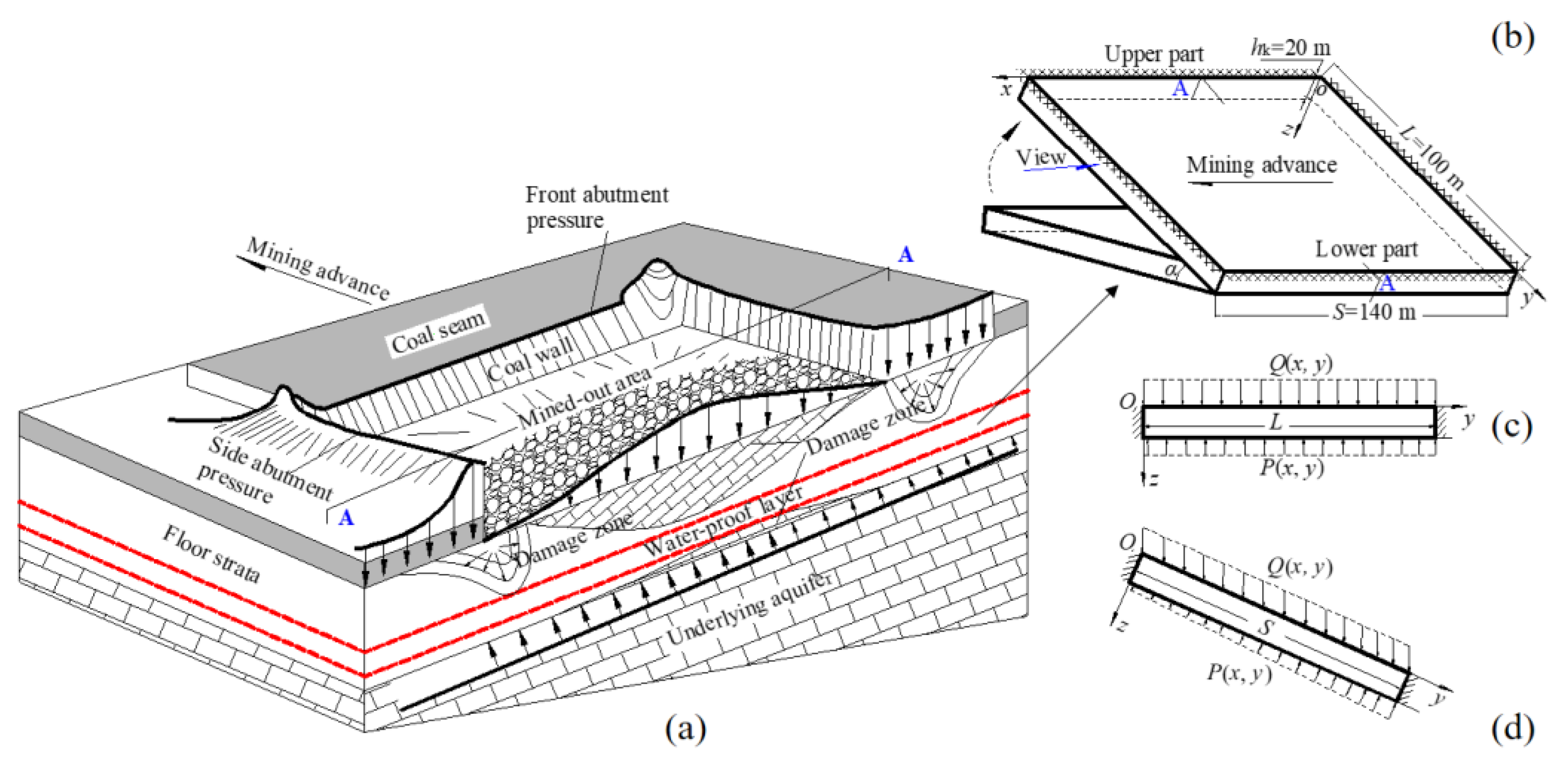
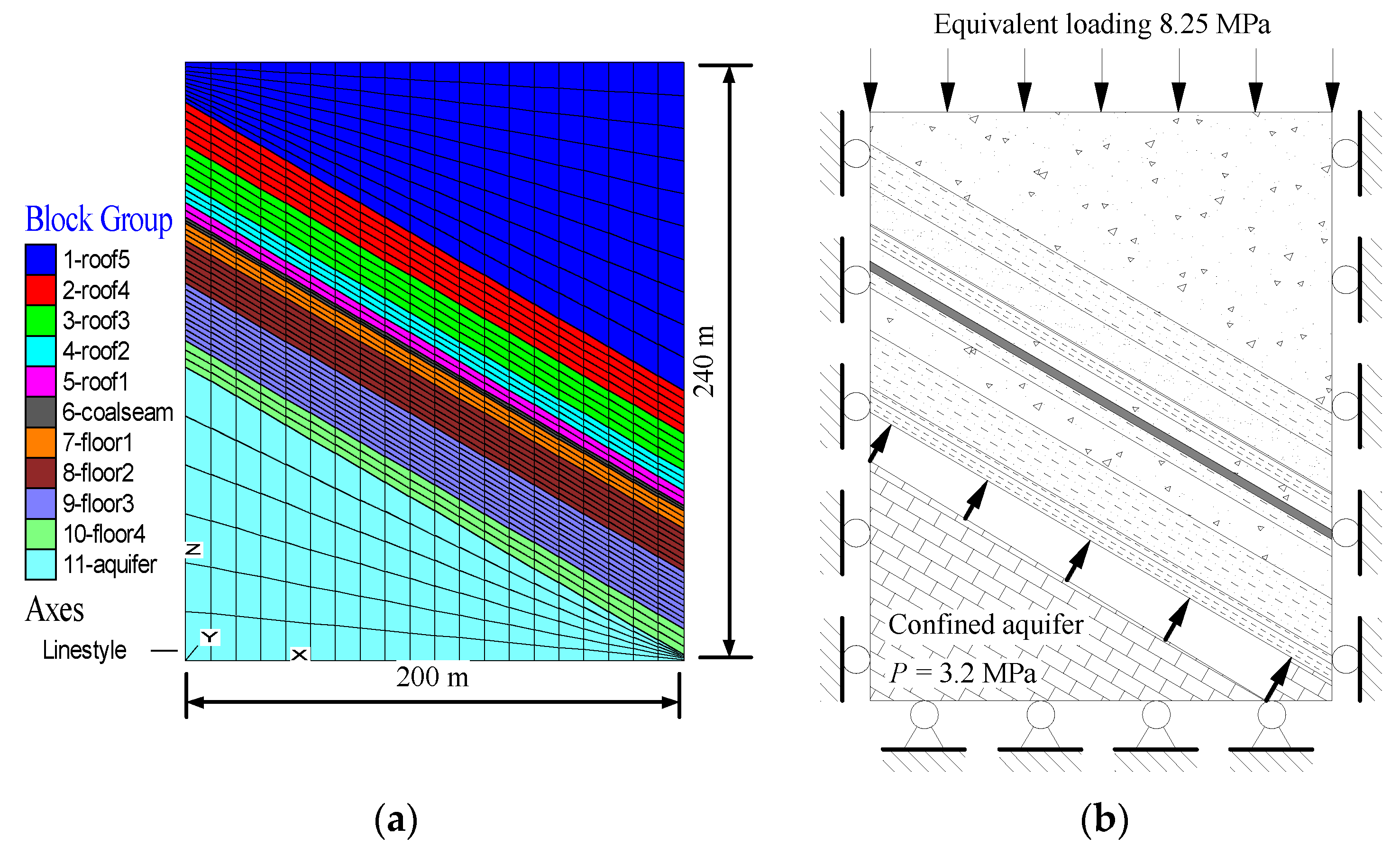
3.1. Modeling Descriptions

Figure 8 clearly shows the mesh division and boundary conditions for the numerical model established using FLAC3D. The model includes roof overburden, coal seam, floor aquiclude and the confined aquifer, and has the geometric dimensions of 200 m (X) × 300 m (Y) × 240 m (Z), with a total of 33,000 elements. The bottom boundary of the numerical model is fully fixed. An equivalent vertical load of 8.25 MPa is uniformly applied on the top boundary to represent the crustal stress resulting from overburdened strata, and the other boundaries are constrained by horizontal displacement. An initial hydraulic pressure of 2.5 MPa is set in the confined aquifer to simulate the effect of groundwater on the floor strata during coal extraction. With regard to the boundary effect, the coal seam is incrementally excavated from Y = 50 m to Y = 250 m, at 10 m per step, totaling 20 steps. All failure calculations are performed according to the Mohr–Coulomb criterion. The values of the physico-mechanical parameters of rocks and the coal seam in the numerical models, as listed in Table 1, are empirically chosen and estimated according to the field test results. Figure 9 shows the geolithological division of the coal and rock strata, in which the thicknesses of the different stratum are rounded to integer values to simplify calculations.

3.2. Numerical Simulation Results

Figure 10 displays the failure depth of the floor with varying excavation distance. The depth of the floor failure is positively correlated with the excavation of the coal seam during the initial and middle stages, following which the relationship stabilized. The simulation results shown in Figure 10 demonstrate that the maximum damage depth of the horizontal stratum above a confined aquifer is roughly 14.57 m when the mining excavation reaches a critical value of 180 m, slightly less than that of the inclined stratum (i.e., 16.71 m).
Subsequent to all calculations, the failure zones in the horizontal and inclined floor rocks were further analyzed, with Figure 11 and Figure 12 showing the profiles in the middle of the numerical models along the inclination. The numerically obtained result of Figure 11 demonstrates that the overall failure mode of the horizontal floor strata is clearly an “inverted saddle”, and the mining-disturbed boundary on both sides (approximately 14.57 m) is deeper than that in the middle (approximately 9 m). By comparison, the distribution of the mining failure zone shows a characteristic pattern of decreasing from the bottom to the top (i.e., upper small and lower large), as evident in Figure 12, and the maximum depth of failure appears in the strata beneath the area around the lower part of the inclined floor. Therefore, the comparison of the theoretical calculations in Figure 5 and the simulated results exhibits good agreement, which can also be confirmed by the previous work of Sun et al. [48]. According to the results of micro-seismic monitoring shown in Figure 13, the damage in the inclined coal mine floor propagates asymmetrically downward in the shape of “down-large-up-small”. Assuming that the area with the deepest depth of floor failure is at most risk to forming a water-inrush channel, a large volume of uncontrolled groundwater in the underlying aquifer may preferentially penetrate into the excavation space through the lower roadway of the inclined floor rock mass, thus resulting in immeasurable casualties and economic losses to underground geological engineering.

4. Discussion and Conclusions

Characterizing the floor failure will be helpful in practice to improve the safety of coal mining above the underlying aquifers. With respect to the effects of mining and hydraulic pressures as well as strata dip, mechanical models were proposed to comparatively investigate the vertical failure ranges and water inrush risk of the horizontal and the inclined floors after excavation. Then, these models were confirmed by numerically simulating the failure characteristics of coal seam floors above the aquifers. The detailed conclusions of the current study can be drawn as the following:
(1)
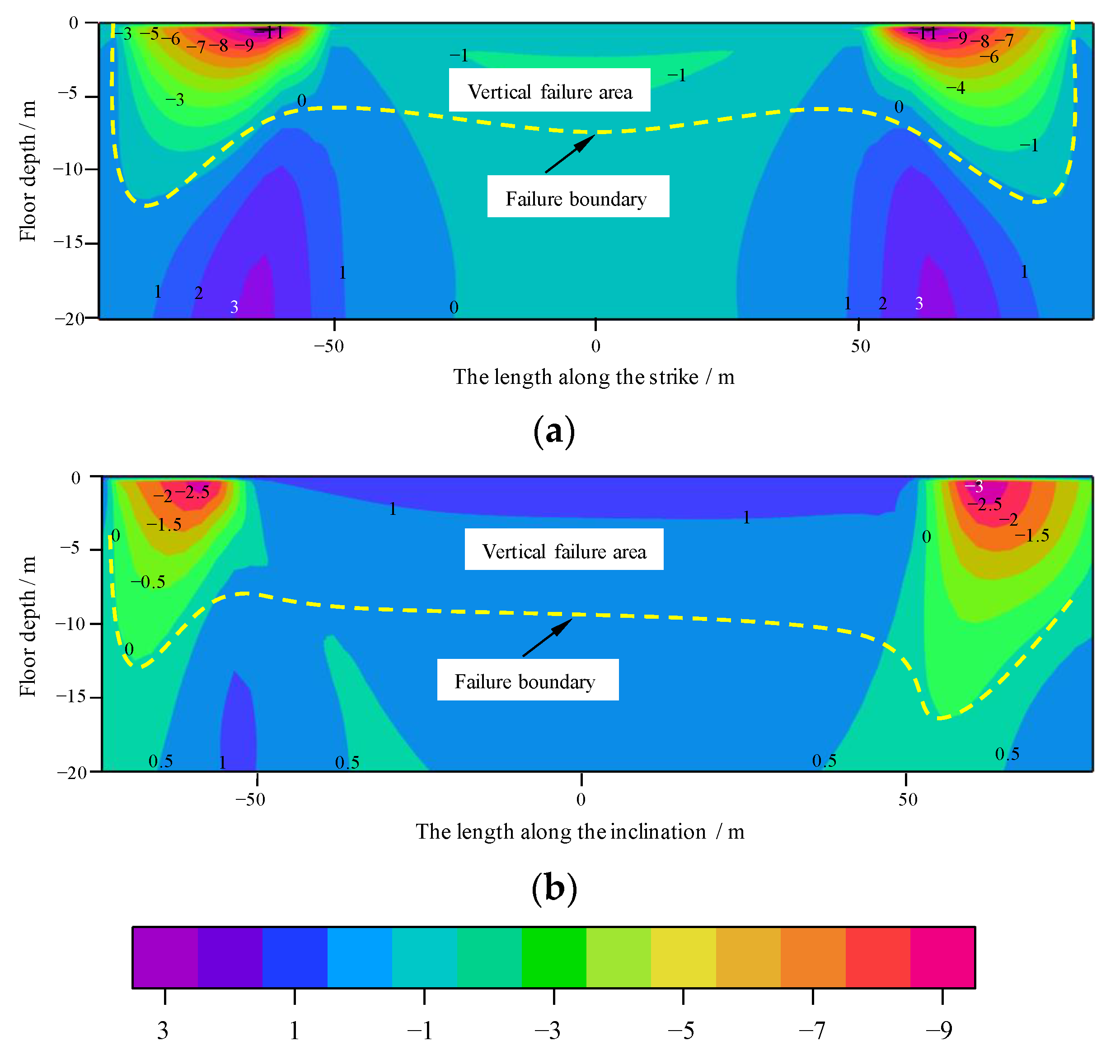
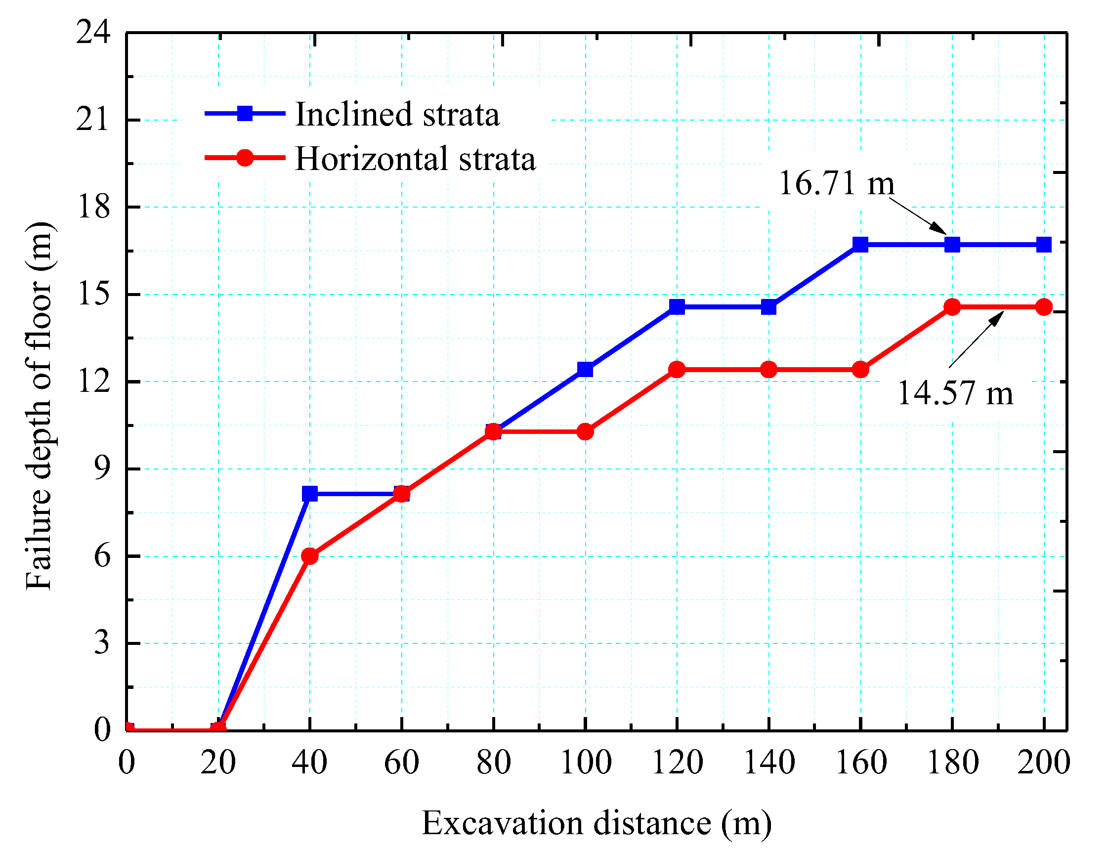
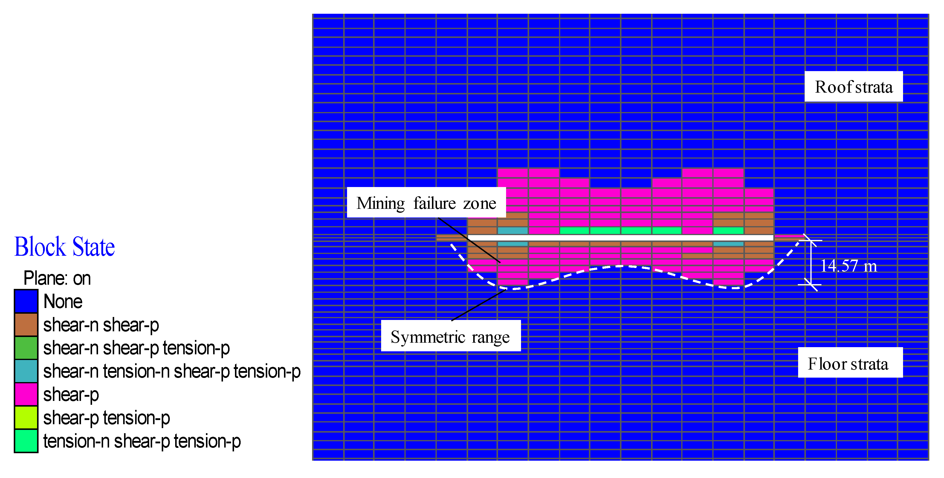
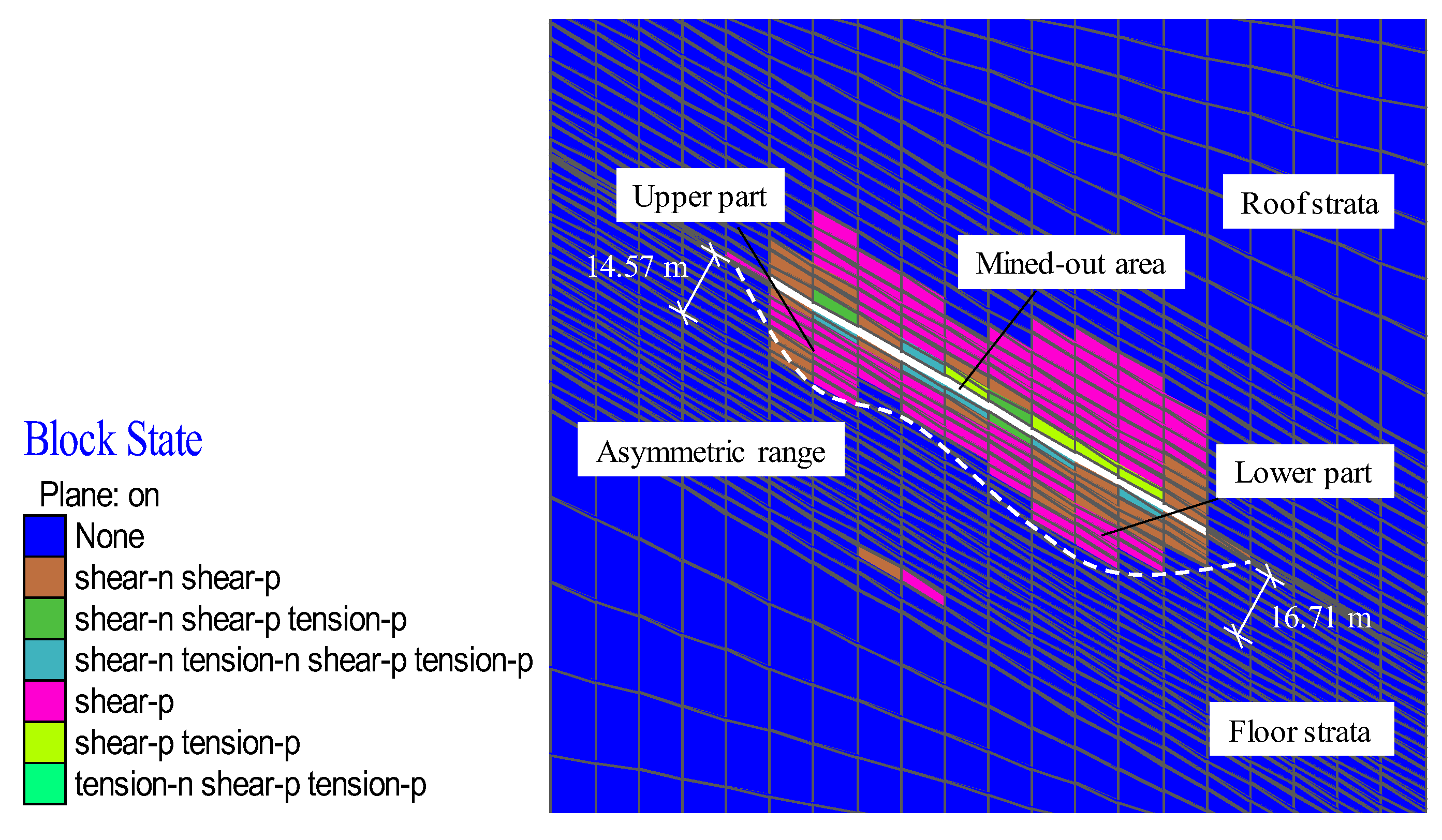
The results of theoretical calculation and numerical simulation exhibit good agreement regarding the ranges of vertical failure of the horizontal and inclined floors. The characteristic of the horizontal floor after coal mining conforms to an approximately “inverted saddle” shape, and shows geometric symmetry along the inclination. Compared with the horizontal floor, the damage zone at the lower end of the inclined stratum presents a wider and deeper range than the upper end.
(2)
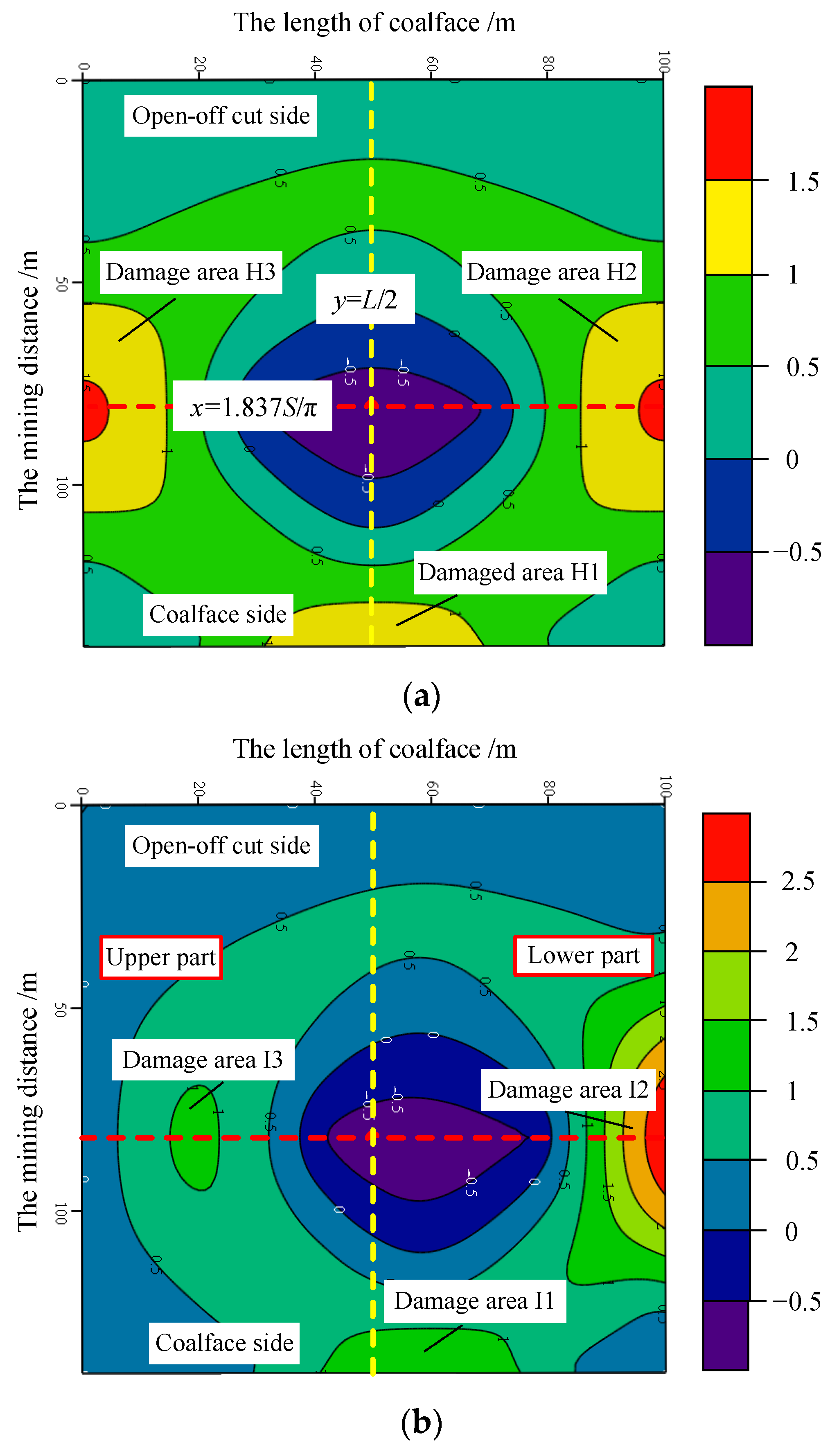
The possibility of groundwater inrush through the sides of the goaf is relatively higher for both the horizontal and inclined seam floors, with their theoretical maximum failure depths roughly 12 m, 15 m (the upper part) and 12.5 m (the lower part). The distribution of the vertical failure ranges is generally consistent with water inrush zoning on the key strata. For example, the damage zones of the remaining waterproof layers, such as zones 1, 2 and 3, are dominantly concentrated near the model boundaries under the mined-out area. The ordering of these zones in terms of water-inrush risk from the horizontal and inclined impermeable layer is R(H2) = R(H3) > R(H1) and R(I2) > R(I1) > R(I3), respectively. Therefore, effective countermeasures such as goaf filling and floor grouting should be implemented within areas of high risk after coal excavation.
(3)
The proposed analytical models are beneficial to a comparative analysis of the failure modes and instability between horizontal and inclined floors. The representation of the fracturing process of the floor rock mass was limited. However, the presented mechanical models reveal the theoretical mechanism inducing the frequent occurrence of inrush disasters at the stope floor close to the rear goaf or the coal wall. Thus, the study results can provide some valuable references for assessing and managing water-related hazards in deep underground engineering.

Author Contributions

Conceptualization, C.Z. and W.S.; methodology, C.Z. and W.S.; software, C.Z.; validation, C.Z. and W.S.; formal analysis, C.Z. and W.S.; investigation, C.Z. and W.S.; data curation, C.Z. and W.S.; writing—original draft preparation, C.Z. and W.S.; writing—review and editing, W.S. All authors have read and agreed to the published version of the manuscript.

Funding

This research received no external funding.

Institutional Review Board Statement

Not applicable.

Informed Consent Statement

Informed consent was obtained from all subjects involved in the study.

Data Availability Statement

The data presented in this study are available on request from the corresponding author. The data are not publicly available due to privacy concerns.

Conflicts of Interest

The authors declare that they have no known competing financial interests or personal relationships that could have appeared to influence the work reported in this paper.

References

  1. Bai, H.; Ma, D.; Chen, Z. Mechanical behavior of groundwater seepage in karst collapse pillars. Eng. Geol. 2013, 164, 101–106. [Google Scholar] [CrossRef]
  2. Farhadian, H.; Katibeh, H.; Huggenberger, P. Empirical model for estimating groundwater flow into tunnel in discontinuous rock masses. Environ. Earth Sci. 2016, 75, 471. [Google Scholar] [CrossRef]
  3. Ma, D.; Rezania, M.; Yu, H.; Bai, H. Variations of hydraulic properties of granular sandstones during water inrush: Effect of small particle migration. Eng. Geol. 2017, 217, 61–70. [Google Scholar] [CrossRef]
  4. Wu, Q.; Zhou, W. Prediction of groundwater inrush into coal mines from aquifers underlying the coal seams in China: Vulnerability index method and its construction. Environmental Geology 2008, 56, 245–254. [Google Scholar] [CrossRef]
  5. Zhang, G.; Jiao, Y.; Ma, C.; Wang, H.; Chen, L.; Tang, Z. Alteration characteristics of granite contact zone and treatment measures for inrush hazards during tunnel construction—A case study. Eng. Geol. 2018, 235, 64–80. [Google Scholar] [CrossRef]
  6. Huang, Z.; Jiang, Z.; Zhu, S.; Qian, Z.; Cao, D. Characterizing the hydraulic conductivity of rock formations between deep coal and aquifers using injection tests. Int. J. Rock Mech. Min. 2014, 71, 12–18. [Google Scholar] [CrossRef]
  7. Liu, H.; Li, L.; Li, Z.; Yu, G. Numerical Modelling of Mining-induced Inrushes from Subjacent Water Conducting Karst Collapse Columns in Northern China. Mine Water Environ. 2018, 37, 652–662. [Google Scholar] [CrossRef]
  8. Mao, D.; Liu, Z.; Wang, W.; Li, S.; Gao, Y.; Xu, Z.; Zhang, C. An application of hydraulic tomography to a deep coal mine: Combining traditional pumping tests with water inrush incidents. J. Hydrol. 2018, 567, 1–11. [Google Scholar] [CrossRef]
  9. Chen, H.; Qi, H.; Long, R.; Zhang, M. Research on 10-year tendency of China coal mine accidents and the characteristics of human factors. Safety Sci. 2012, 50, 745–750. [Google Scholar] [CrossRef]
  10. Lamoreaux, J.W.; Wu, Q.; Wanfang, Z. New development in theory and practice in mine water control in China. Carbonate Evaporite 2014, 29, 141–145. [Google Scholar] [CrossRef] [Green Version]
  11. Wang, X.; Meng, F. Statistical analysis of large accidents in China’s coal mines in 2016. Nat. Hazards 2018, 92, 311–325. [Google Scholar] [CrossRef]
  12. Zhang, J.; Xu, K.; Reniers, G.; You, G. Statistical analysis the characteristics of extraordinarily severe coal mine accidents (ESCMAs) in China from 1950 to 2018. Process Saf. Environ. 2020, 133, 332–340. [Google Scholar] [CrossRef]
  13. Miao, X.; Cui, X.; Wang, J.; Xu, J. The height of fractured water-conducting zone in undermined rock strata. Eng. Geol. 2011, 120, 32–39. [Google Scholar] [CrossRef]
  14. Meng, Z.; Shi, X.; Li, G. Deformation, failure and permeability of coal-bearing strata during longwall mining. Eng. Geol. 2016, 208, 69–80. [Google Scholar] [CrossRef]
  15. Lu, Y.; Wang, L. Numerical simulation of mining-induced fracture evolution and water flow in coal seam floor above a confined aquifer. Comput. Geotech. 2015, 67, 157–171. [Google Scholar] [CrossRef]
  16. Yin, S.; Zhang, J.; Liu, D. A study of mine water inrushes by measurements of in situ stress and rock failures. Nat. Hazards 2015, 79, 1961–1979. [Google Scholar] [CrossRef]
  17. Zhao, J.; Feng, X.; Jiang, Q.; Zhou, Y. Microseismicity monitoring and failure mechanism analysis of rock masses with weak interlayer zone in underground intersecting chambers: A case study from the Baihetan Hydropower Station, China. Eng. Geol. 2018, 245, 44–60. [Google Scholar] [CrossRef]
  18. Wang, J.A.; Park, H.D. Fluid permeability of sedimentary rocks in a complete stress–strain process. Eng. Geol. 2002, 63, 291–300. [Google Scholar] [CrossRef]
  19. Wu, N.; Liang, Z.; Li, Y.; Qian, X.; Gong, B. Effect of confining stress on representative elementary volume of jointed rock masses. Geomech. Eng. 2019, 18, 627–638. [Google Scholar]
  20. Liang, Z.; Wu, N.; Li, Y.; Li, H.; Li, W. Numerical Study on Anisotropy of the Representative Elementary Volume of Strength and Deformability of Jointed Rock Masses. Rock Mech. Rock Eng. 2019, 52, 4387–4402. [Google Scholar] [CrossRef]
  21. Castelli, F.; Grasso, S.; Lentini, V.; Sammito, M.S.V. Effects of Soil-Foundation-Interaction on the Seismic Response of a Cooling Tower by 3D-FEM Analysis. Geosciences 2021, 11, 200. [Google Scholar] [CrossRef]
  22. Liang, Z.; Song, W.; Liu, W. Theoretical models for simulating the failure range and stability of inclined floor strata induced by mining and hydraulic pressure. Int. J. Rock Mech. Min. 2020, 132, 104382. [Google Scholar] [CrossRef]
  23. Zhu, S.; Jiang, Z.; Zhou, K.; Peng, G.; Yang, C. The characteristics of deformation and failure of coal seam floor due to mining in Xinmi coal field in China. B. Eng. Geol. Environ. 2014, 73, 1151–1163. [Google Scholar] [CrossRef]
  24. Zhang, J. Investigations of water inrushes from aquifers under coal seams. Int. J. Rock Mech. Min. 2005, 42, 350–360. [Google Scholar] [CrossRef]
  25. Huang, Z.; Li, X.; Li, S.; Zhao, K.; Zhang, R. Investigation of the hydraulic properties of deep fractured rocks around underground excavations using high-pressure injection tests. Eng. Geol. 2018, 245, 180–191. [Google Scholar] [CrossRef]
  26. Sun, W.B.; Xue, Y.C.; Yin, L.M.; Zhang, J.M. Experimental study on seepage characteristics of large size rock specimens under three-dimensional stress. Geomech. Eng. 2019, 18, 567–574. [Google Scholar]
  27. Yang, T.; Liu, H.Y.; Tang, C.A. Scale effect in macroscopic permeability of jointed rock mass using a coupled stress–damage–flow method. Eng. Geol. 2017, 228, 121–136. [Google Scholar] [CrossRef]
  28. Yu, C.; Tang, S.; Tang, C.; Duan, D.; Zhang, Y.; Liang, Z.; Ma, K.; Ma, T. The effect of water on the creep behavior of red sandstone. Eng. Geol. 2019, 253, 64–74. [Google Scholar] [CrossRef]
  29. Li, L.C.; Yang, T.H.; Liang, Z.Z.; Zhu, W.C.; Tang, C.A. Numerical investigation of groundwater outbursts near faults in underground coal mines. Int. J. Coal Geol. 2011, 85, 276–288. [Google Scholar]
  30. Yang, T.H.; Liu, J.; Zhu, W.C.; Elsworth, D.; Tham, L.G.; Tang, C.A. A coupled flow-stress-damage model for groundwater outbursts from an underlying aquifer into mining excavations. Int. J. Rock Mech. Min. 2007, 44, 87–97. [Google Scholar] [CrossRef]
  31. Sun, J.; Miao, X. Water-Isolating Capacity of an Inclined Coal Seam Floor Based on the Theory of Water-Resistant Key Strata. Mine Water Environ. 2017, 36, 310–322. [Google Scholar] [CrossRef]
  32. Wu, Q.; Liu, Y.; Liu, D.; Zhou, W. Prediction of Floor Water Inrush: The Application of GIS-Based AHP Vulnerable Index Method to Donghuantuo Coal Mine, China. Rock Mech. Rock Eng. 2011, 44, 591–600. [Google Scholar] [CrossRef]
  33. Wu, Q.; Zhao, D.; Wang, Y.; Shen, J.; Mu, W.; Liu, H. Method for assessing coal-floor water-inrush risk based on the variable-weight model and unascertained measure theory. Hydrogeol. J. 2017, 25, 2089–2103. [Google Scholar] [CrossRef]
  34. Li, W.; Liu, Y.; Qiao, W.; Zhao, C.; Yang, D.; Guo, Q. An Improved Vulnerability Assessment Model for Floor Water Bursting from a Confined Aquifer Based on the Water Inrush Coefficient Method. Mine Water Environ. 2018, 37, 196–204. [Google Scholar] [CrossRef]
  35. Meng, Z.; Li, G.; Xie, X. A geological assessment method of floor water inrush risk and its application. Eng. Geol. 2012, 143–144, 51–60. [Google Scholar] [CrossRef]
  36. Shi, L.; Qiu, M.; Wang, Y.; Qu, X.; Liu, T. Evaluation of water inrush from underlying aquifers by using a modified water-inrush coefficient model and water-inrush index model: A case study in Feicheng coalfield, China. Hydrogeol. J. 2019, 27, 2105–2119. [Google Scholar] [CrossRef]
  37. Wang, Y.; Yang, W.; Li, M.; Liu, X. Risk assessment of floor water inrush in coal mines based on secondary fuzzy comprehensive evaluation. Int. J. Rock Mech. Min. 2012, 52, 50–55. [Google Scholar] [CrossRef]
  38. Zhao, D.; Wu, Q.; Cui, F.; Xu, H.; Zeng, Y.; Cao, Y.; Du, Y. Using random forest for the risk assessment of coal-floor water inrush in Panjiayao Coal Mine, northern China. Hydrogeol. J. 2018, 26, 2327–2340. [Google Scholar] [CrossRef]
  39. Xu, Z.L. Concise Tutorial on Elasticity; Higher Education Press: Beijing, China, 2002. [Google Scholar]
  40. Sun, J.; Wang, L.; Zhao, G. Failure Characteristics and Confined Permeability of an Inclined Coal Seam Floor in Fluid-Solid Coupling. Adv. Civ. Eng. 2018, 2018, 2356390. [Google Scholar] [CrossRef]
  41. Zhang, H.; Wan, Z.; Feng, Z.; Wu, J. Shear-induced permeability evolution of sandstone fractures. Geofluids 2018, 2018, 2416481. [Google Scholar] [CrossRef]
  42. Shen, M.R.; Chen, J.F. Mechanics of Rock Masses; Tongji University Publishing House: Shanghai, China, 2006. [Google Scholar]
  43. Sun, W.; Zhang, S.; Guo, W.; Liu, W. Physical Simulation of High-Pressure Water Inrush Through the Floor of a Deep Mine. Mine Water Environ. 2017, 36, 542–549. [Google Scholar] [CrossRef]
  44. Bukowski, P. Water Hazard Assessment in Active Shafts in Upper Silesian Coal Basin Mines. Mine Water Environ. 2011, 30, 302–311. [Google Scholar] [CrossRef]
  45. Qian, Z.; Huang, Z.; Song, J. A case study of water inrush incident through fault zone in China and the corresponding treatment measures. Arab. J. Geosci. 2018, 11, 381. [Google Scholar] [CrossRef]
  46. Zhou, J.; Yang, T.; Zhang, P.; Xu, T.; Wei, J. Formation process and mechanism of seepage channels around grout curtain from microseismic monitoring: A case study of Zhangmatun iron mine, China. Eng. Geol. 2017, 226, 301–315. [Google Scholar] [CrossRef]
  47. Sainoki, A.; Mitri, H.S. Dynamic behaviour of mining-induced fault slip. Int. J. Rock Mech. Min. 2014, 66, 19–29. [Google Scholar] [CrossRef]
  48. Sun, J.; Wang, L.G.; Tang, F.R.; Shen, Y.F.; Gong, S.L. Microseismic monitoring failure characteristics of inclined coal seam floor. Rock Soil Mech. 2011, 32, 1589–1595. [Google Scholar]
Figure 1. Water-related mining accidents in China from 2000 to 2021.
Applsci 12 12164 g001
Figure 2. Spatial redistribution of mechanical loads on the seam floor above an aquifer. A-A represents the section along the inclination.
Applsci 12 12164 g002
Figure 3. Hydraulic-mechanical (HM) models for seam floors. (a) A case with horizontal strata; (b) A case with inclined strata.
Applsci 12 12164 g003
Figure 4. Decomposition of vertical load acting on the upper boundary in Figure 3b.
Applsci 12 12164 g004
Figure 5. The theoretically obtained failure ranges of floor strata resulting from mining and hydraulic pressures. (a) A case with horizontal strata; (b) A case with inclined strata.
Applsci 12 12164 g005
Figure 6. Analytical models for waterproof key strata. (a) Position of the waterproof layer; (b) horizontal or inclined key strata models; (c) profile A-A along the horizontal model; (d) profile A-A along the inclined model.
Applsci 12 12164 g006
Figure 7. Water inrush zoning on the key strata (top view of the models in Figure 6b). (a) A case with horizontal key strata; (b) A case with inclined key strata.
Applsci 12 12164 g007
Figure 8. Mesh division and boundary conditions of numerical model established using FLAC3D (taking an inclined strata model as an example). (a) mesh division; (b) boundary conditions.
Applsci 12 12164 g008
Figure 9. The geolithological division of the coal and rock strata.
Applsci 12 12164 g009
Figure 10. Failure depth of the floor with varying excavation distance.
Applsci 12 12164 g010
Figure 11. Distribution of the numerically obtained failure zone in the horizontal floor strata.
Applsci 12 12164 g011
Figure 12. Distribution of the numerically obtained failure zone in the inclined floor strata.
Applsci 12 12164 g012
Figure 13. Results of micro-seismic monitoring of floor failure by Sun et al. [48]. (a) Top view; (b) Profile view along the inclination.
Applsci 12 12164 g013
Table 1. Physico-mechanical parameters of rocks and the coal seam.
No.γ/(g·cm−3)G/(MPa)K/(MPa)c/(MPa)φ/(°)σt/(MPa)nk/(m2·(Pa·s)−1)
Roof 52.53.6 × 1034.2 × 1034.5333.70.33 × 10−15
Roof 42.72.8 × 1034.5 × 1035.2323.60.45 × 10−14
Roof 32.64.3 × 1034.1 × 1035.8324.20.33 × 10−14
Roof 22.62.0 × 1033.0 × 1033.2312.80.24 × 10−16
Roof 12.53.6 × 1034.2 × 1034.5333.70.33 × 10−15
Coal seam1.40.6 × 1031.3 × 1032.3201.60.53 × 10−13
Floor 12.72.8 × 1034.5 × 1035.2323.60.45 × 10−14
Floor 22.53.6 × 1034.2 × 1034.5333.70.33 × 10−15
Floor 32.72.8 × 1034.5 × 1035.2323.60.45 × 10−14
Floor 42.62.0 × 1033.0 × 1033.2312.80.24 × 10−16
Aquifer2.51.6 × 1032.3 × 1032.0302.20.78 × 10−7
Note: γ—unit weight; G—shear modulus; K—bulk modulus; c—cohesive strength; φ—frictional angle; σt—tensile strength; n—porosity; k—permeability.
Publisher’s Note: MDPI stays neutral with regard to jurisdictional claims in published maps and institutional affiliations.

