3.2.1. Thrust Production
The thrust force is simply a force that advances toward the flow as a component force induced by the deformation of the plate. The thrust force, , in the x-direction is computed as = 0.5 , where is the thrust coefficient, U is the maximum translational velocity of model fin, is the fluid density and a is the reference area of the plate. The mean thrust shown can be obtained by averaging the instantaneous thrust values over the entire flapping cycle.
In the corresponding experiments, the thrust force was calculated from the momentum integration theorem. The plate did not move while it was vibrated in the
z-direction and the velocity fields around the flapping plate were measured by PIV [
25]. In the present study, the thrust force
and thrust coefficients
are calculated using a post-processing function tool available in OpenFOAM.
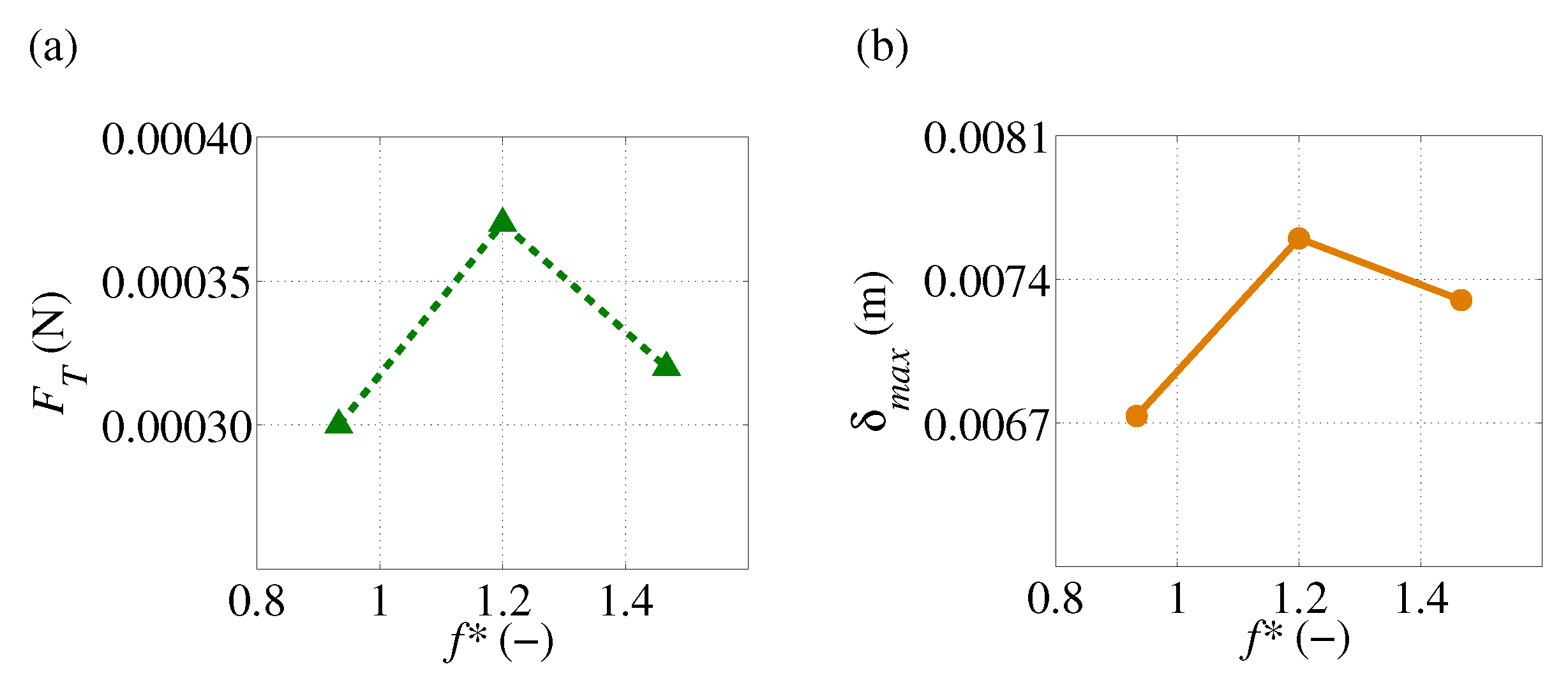
Figure 5a shows the variation of mean thrust force with different
, which can be used to reveal the effect of
on the propulsive characteristics more clearly and quantitatively. It illustrates that the thrust gradually increases with
. Thrust increases with
and reaches a maximum at a certain value of
. However, after reaching a certain value of
, the mean thrust of the plate decreases gradually. This presents an indication that there is an optimal value of
at which the plate achieves the highest mean thrust. For the frequency range considered in our simulations, it is observed that the maximum net thrust occurs at
= 1.2 and the corresponding phase lag is observed to be 0.62
radians. The trend of variation in thrust is observed to be consistent with that in [
25].
In this situation, the magnitude of trailing edge amplitude seems to be irrelevant to the generation of maximum thrust force since it decrease monotonically with flapping frequency as shown in
Figure 3a. It would seem that the generation of maximum thrust force comes from the phase lag due to deformation, which makes a difference in the displacement of the trailing edge relative to the displacement of leading edge.
Figure 5b shows the maximum deformation of the trailing edge relative to the leading edge for all cases. Note that the instantaneous displacement of leading edge
is subtracted from that of trailing edge
to obtain the instantaneous relative displacement of the trailing edge in a flapping cycle,
, from which the maximum relative deformation of trailing edge,
, is estimated. This means that the amplitude of the instantaneous relative displacement of trailing edge in a flapping cycle is taken as the maximum relative deformation of trailing edge
.
According to
Figure 5a,b, the maximum net thrust is found to be associated with the maximum value in the relative deformation of trailing edge. It is evident that the phase lag is due to deformation of the plate, which makes a difference in the relative deformation of the trailing edge with respect to the leading edge, influences the generation of thrust force. Notably, the optimal value of
for maximum thrust generation in this plate does not coincide with the optimal value of
for the elastic structure.
Figure 6 shows the instantaneous displacement of the trailing edge relative to that of the leading edge,
, in a flapping cycle for all cases to clarify the features of maximum and minimum thrust force in a flapping cycle. In this Figure, the phase instant when the maximum and minimum thrust appears in each case is marked with red and black squares, respectively. The comparison of instantaneous thrust force,
during one heaving cycle between different
is shown in
Figure 7. The results are computed from a heaving cycle that reaches a periodic steady state.
Due to the symmetric heaving motion of the plate, the result of
in
Figure 7 shows two distinct peaks in a heaving cycle. A slight value of negative thrust is observed around the reversal phase of leading-edge motion in all cases. The peak value of negative thrust is also affected by the
. The maximum positive thrust occurs after the start of each half cycle where the maximum amplitude of trailing edge appears in all cases. The effect of
are clearly observed in the instantaneous thrust production. The largest fluctuation of
is observed in the case of
= 1.2. Two significant areas of interest are seen in
Figure 7; one is at a point marked with a red square, a phase instant when a peak value of positive thrust appears in each case and the other one is at a point marked with a black square, a phase instant when a peak value of negative thrust appears in each case.
When the thrust force
in each case is non-dimensionalized by 0.5
, the corresponding thrust coefficient
is obtained for each case. The variations of mean thrust coefficient with different
are shown in
Figure 8. Since the thrust coefficient is inversely proportional to the square of the maximum translational velocity of the leading edge,
, the mean thrust coefficient shows a decreasing trend as the flapping frequency is increased. Interestingly, the trend of the mean thrust coefficient is nearly linear and well correlated with the declining trend of trailing edge’s amplitude through the selected frequency range. This is consistent with our previous finding for heaving rectangular plate, in which the maximum thrust force coefficient was related to the maximum non-dimensional amplitude of the trailing edge [
29].
3.2.2. Pressure Distribution and Vortex Structure
In this section, the pressure distributions around the plate surfaces and the relative deformation of trailing edge are examined to investigate why the thrusts produced by the plate differ with
. The pressure difference between the upper and lower surface of the plate is the source of propulsion. The non-dimensional frequency of
= 0.93, 1.2 and 1.47 are termed as case 1, case 2 and case 3, respectively.
Figure 9 shows the pressure distributions on the spanwise symmetry plane of the plate in a half-flapping cycle for case 1 at the phase instants of
= 0, 0.125, 0.25, 0.375 and 0.5. In the first half-cycle, from
= 0 to
= 0.5, the leading edge of the plate shifts from its center position with the upward motion and then returns to its center position with the downward motion.
At = 0.000, the plate is at the start of the first half-cycle with the maximum velocity of the leading edge and its leading edge beginning to move from its center position with upward motion. As the plate is gaining speed, a very large pressure field is observed in both positive and negative around both surface of the plate. Consequently, a high pressure difference between the two surfaces is created, which results in the generation of thrust in the positive x direction at this phase instant.
At
= 0.125, the leading edge continues its upward motion and the velocity of the leading edge decreases. During the decelerating phase of the leading edge, the positive- and negative-pressure regions around the leading edge seem to be decayed and distributed mostly on the region near the trailing edge of the plate as shown in the second diagram of
Figure 9. With the decreasing trend of thrust in
Figure 7, the pressure difference between the two surfaces of the plate is also decreasing. This demonstrates that the plate produces a smaller positive thrust than the phase instant described above, which is well correlated with the declining of thrust at this phase instant.
At = 0.250, the leading edge reaches the end of its upward motion and the reversal phase with zero velocity. It is observed that a very low-pressure region is attached to the trailing edge of the plate, which results in a significant decrease in thrust force at this phase instant. A region of very low-pressure difference is also observed to be generated near the region of the leading edge, and the plate cannot force water backward adequately to produce forward motion. This is consistent with the generation of the negative value of thrust at this phase instant.
At = 0.375, the leading edge is en route back to its center with the downward motion with velocity of the leading edge increasing. As the leading edge is moving downwards in the accelerating phase, the plate pushes against the water with the lower surface creating the positive-pressure region around it. Meanwhile, the plate pulls the fluid on the upper surface of the plate, which creates a negative-pressure region on the upper surface of the plate. As a result, the plate creates a larger pressure difference between the two surfaces, which leads to a larger positive thrust at this phase instant.
At = 0.500, the leading edge reaches the end of the accelerating phase with downward motion to its center. As the leading edge is at the maximum velocity, the positive and negative pressures develop highly below and above the entire surface of the plate. As a result, the thrust forces are greatly enhanced at this time instant. In particular, the thrust force of the plate has already reached the maximum value before this phase instant. These phenomena are well correlated with the trend of thrust in a half-flapping cycle. After the first half-flapping cycle, the plate continues its motion for the second half-cycle, from = 0.500 to = 1.000.
The evolution of three-dimensional vortex structures at the corresponding phases during the half-flapping cycle are illustrated in
Figure 10 as an iso-surface of the Q-criterion (Q = 30) filled with the spanwise vorticity Y. The three vortices evolved along the side, leading edge and trailing edge of the plate, respectively. Among the three vortex structures, it is found that the vortex evolved from the trailing edge of the plate (TEV) mainly produces the low-pressure region on the plate surface.
From
= 0.000 to
= 0.125, a counterclockwise TEV (red color) emerges from the trailing edge on the lower surface of the plate. Subsequently, there is a low-pressure region on the plate’s lower surface as seen in
Figure 9. This TEV continues to grow in size and remains attached to the trailing edge of the plate until the velocity of the trailing edge reaches maximum. At
= 0.250, it can be seen that the TEV has fully developed and starts to detach from the plate. This is consistent with the circular area of the low-pressure region seen at the trailing edge on the lower surface of the plate (
Figure 9). After that, the TEV detaches from the plate and sheds into the downstream flow field on the lower side of the plate.
At
= 0. 375, the shedding of TEV into the wake is observed, which is well correlated with a low-pressure circular region in the downstream on the lower side of the plate as seen in
Figure 9. Meanwhile, the plate holds positive- and negative-pressure regions on its lower and upper surface, respectively, due to the downward motion of the plate (
Figure 9). The shedding of TEV into the downstream wake coincides with the increasing trend in thrust force.
At
= 0.500, the shed counterclockwise TEV is losing its strength and starts to decay. In the corresponding pressure field (
Figure 9), dissipation of the low-pressure circular region is still visible in the near wake region below the plate. This phenomenon can also be related to the trend of declination in thrust force. Specifically, the thrust force reaches maximum position just before this phase instant. The period of TEV shedding into the downstream wake coincides with the period of increasing thrust from the minimum position to the maximum position. Alternatively, a new clockwise TEV (blue color) starts to form at the trailing edge on the upper surface of the plate and the next half-cycle starts with the development of a new TEV.
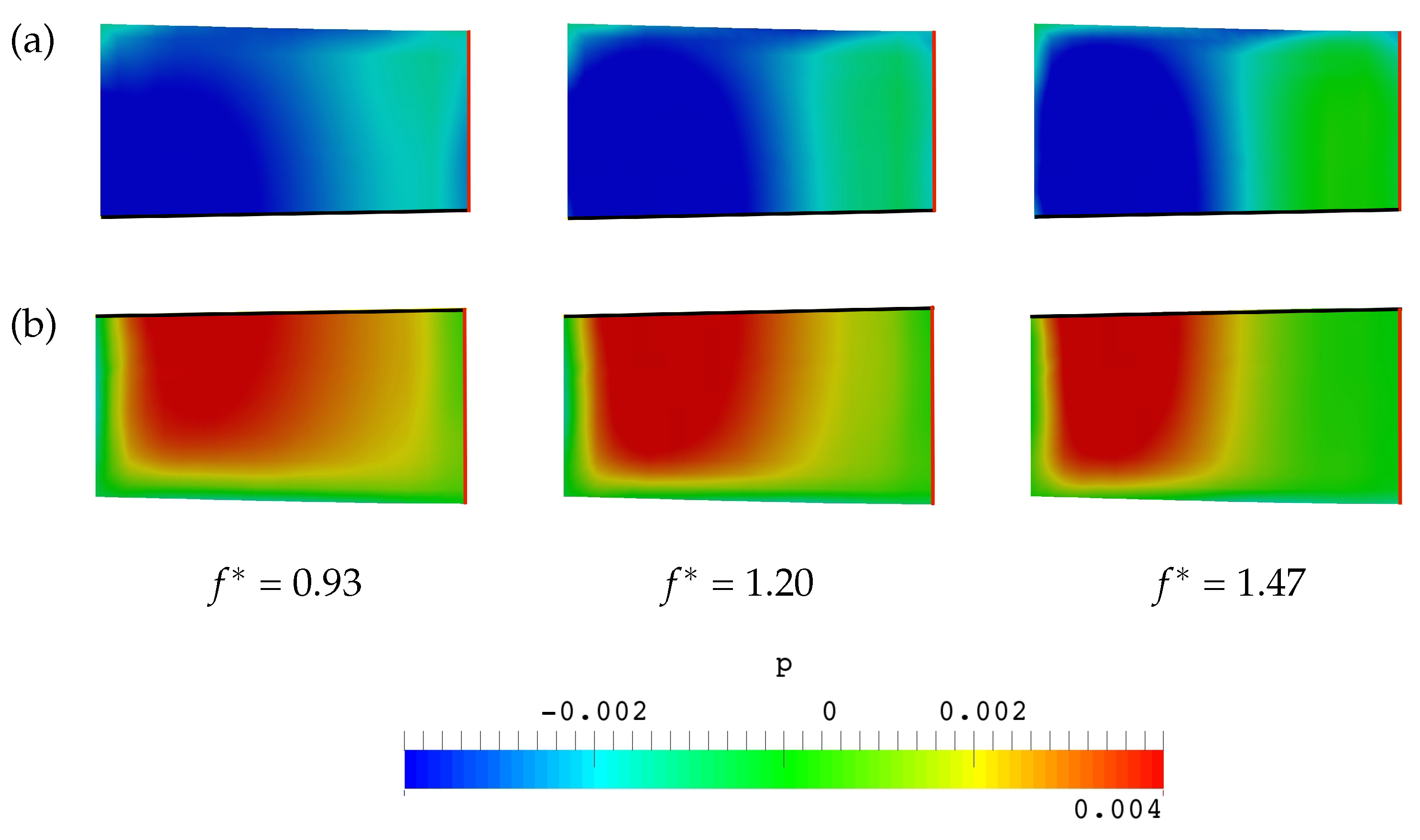
Figure 11a and
Figure 12 show the comparison of pressure distribution on both sides of the plate surface for all cases at a phase instant when a peak value of positive thrust appears in all cases. The corresponding vortex structures around the plate are illustrated in
Figure 11b. The phase instant at which a peak of positive thrust appears in each case can be seen in
Figure 7, where points a, b and c are representative phase instants corresponding to
= 0.489,
= 0.561 and
= 0.611 for case 1, case 2 and case 3, respectively.
According to
Figure 11a and
Figure 12, the high pressure acting on the lower side of the plate in the case of an optimal frequency
= 1.2 (case 2) is significantly larger than those in the other two cases. Consequently, case 2 exhibits the largest pressure difference among the three cases, which is consistent with the generation of the highest instantaneous positive thrust at the phase instant of
= 0.561 (point b in
Figure 7) in case 2.
It is likely that the relative deformation of the trailing edge affects the distribution of pressure around the plate surface. When examining the pressure distribution on the plate surface of all cases, it is seen that the negative-pressure regions on the upper surface of the plate appear similar as seen in
Figure 12a. It would seem that the positive-pressure region below the plate surface as seen in
Figure 12b is creating the increase in thrust force.
In the case of
= 0.93 (case 1), as shown in
Figure 11a, the leading edge is at the phase instant of
= 0.489 and approaching the end of its acceleration phase with downward motion to its center. Meanwhile, the trailing edge is also on the way of a return stroke with downwards motion to its center in an acceleration phase. Since both the leading edge and trailing edge of the plate are in the accelerating phase with downward motion, the positive pressure is observed to be widely distributed along most of the lower surface of the plate.
From the first diagram of
Figure 12b, it is seen that the positive-pressure region is enlarged from the leading edge to the trailing edge of the plate surface. Due to the relative velocity of the trailing edge and leading edge, asymmetric pressure is created on the lower surface of the plate. The positive-pressure field is more concentrated near the trailing edge region due to increasing displacement of the trailing edge. The pressure difference between the two surfaces is observed to be lowest among the three cases, which is consistent with the generation of smallest positive thrust in case 1. The lowest pressure difference in this case is attributed to the smallest relative displacement of trailing edge with that of leading edge as shown in
Figure 6 (see point a).
In the cases of
= 1.2 and
= 1.47, the trailing edge exhibits out-of-phase motion and a shorter time of in-phase motion with the leading edge throughout most of a flapping stroke due to larger phase lag. As the
increases, the high-pressure region on the lower surface of the plate shifts from the region near the leading edge to the region near the trailing edge and develops more around the trailing edge region as shown in
Figure 11a.
As illustrated in
Figure 11a, the leading edge of case 2 (
= 1.2) is starting its second half-cycle with downward motion from its center position while the trailing edge is reversing its direction of motion to its center. Consequently, the leading edge is in a decelerating phase while the trailing edge is in an accelerating phase. Due to deceleration of the leading edge during its second half-cycle, it was observed that the positive pressure around half of the leading edge region dissipates while acceleration of the trailing edge leads to a notable development of positive pressure on most of the trailing edge region. The pressure difference between the two surfaces of the plate is observed to be the largest among the three cases, which is related to the generation of highest positive thrust at the phase instant of
= 0.561 (point b in
Figure 7) in case 2. The reason for the largest pressure difference at this phase instant is consistent with the largest displacement of trailing edge relative to the leading edge as illustrated in
Figure 6 (see point b).
As the
increases, the out-of-phase motion of the trailing edge becomes more pronounced due to larger phase lag of the trailing edge. In
Figure 11a, the leading edge of case 3 (
= 1.47) is already on the way of its second half-cycle with downward motion from its center position while the trailing edge is at the beginning of its reverse motion to the center. Consequently, the leading edge is in a decelerating phase while the trailing edge is at the start of an accelerating phase. Deceleration of the leading edge causes most of its surrounding pressure to disappear. Meanwhile, the trailing edge is about to start its accelerating phase and delays to create a very large-pressure region along the lower surface of the plate. The positive pressure is observed to be mainly focused around the trailing edge region as shown in
Figure 11a. When compared with case 2, this positive-pressure region in case 3 is observed to be smaller and hence the pressure difference in case 3 is also smaller. This seems to contribute to the lower value of maximum positive thrust in case 3 than in case 2. The above phenomenon is also reflected in the relative deformation of the trailing edge in comparison of case 2 with case 3 (see points b and c in
Figure 6).
The difference in phase lag, which causes the difference in relative deformation of the trailing edge with respect to the leading edge, is found to be a key factor in estimating the flow field and associated thrust production. The optimal phase lag for maximum thrust production may be associated with the maximum relative deformation. Thrust force was shown to enhance when the motion of trailing edge is out of phase with that of leading edge.
Figure 13 shows a comparison of the pressure distribution on both sides of the plate surface for all cases at a phase instant when a peak value of negative thrust appears in each case. The phase instant at which a peak of negative thrust appears in each case is presented in
Figure 7, where points d, e, and f are representative phase instants corresponding to
= 0.244,
= 0.318 and
= 0.358 for case 1, case 2 and case 3, respectively. The generation of negative thrust in each case is also reflected in the relative deformation of the trailing edge as shown in
Figure 6, where the phase instant of the minimum thrust force in each case is marked with black squares.
At these phase instants, it is observed that the plate holds the circular low-pressure region closer to its trailing edge, which results in a significant decrease in thrust force. However, these low-pressure regions seem quite similar in all cases, especially in cases 2 and 3. This similarities can be confirmed by the TEV structure as shown in the front and top views of
Figure 14a,b. It would seem that an extra increase in negative thrust arises from the pressure difference created near the leading edge region. Due to the pressure difference created near the leading edge region, the plate cannot push the water sufficiently backward to produce forward motion, which seems to cause an extra increase in negative value of thrust in cases 2 and 3 at these phase instants.
For the case of
= 0.93 (case 1), the leading edge is approaching the end of its decelerating phase with upward motion from the center position and its velocity is approaching zero. This results in the decaying of the positive and negative pressure around the leading edge and a slight difference in pressure distribution is observed around the leading edge as shown in
Figure 13a.
For the cases of
= 1.2 and
= 1.47 (case 2 and 3), the leading edge is in an accelerating phase with downward motion to its center position and its velocity is increasing to maximum. In these two cases, the generation of positive and negative pressure can be observed clearly around the leading edge as shown in
Figure 13b,c. Among the three cases, the pressure difference, which is mainly developed near the leading edge, is observed to be largest in case 3. This largest pressure difference acts to push the plate backward, which is consistent with a massive increase in negative value of thrust at this phase instant of case 3. The largest value of negative thrust in case 3 is observed to be associated with the largest negative value of relative deformation as shown in
Figure 6 (see point f).


