1. Introduction
With the use of computer technology, designers have taken their imagination to the next level thanks to the advantages of digital possibilities and they have increased their pursuit of form finding, and started to fabricate forms in complex shapes using new design and production possibilities. However, the production processes of complex design products also contain complex problems. Therefore, the use of computer technologies is not limited to the design phase, but also in the fabrication processes of complex design products.
Parametric-design tools have evolved in such a way that both the design process and the fabrication process can be controlled with parameters. By changing the parameters, the design product as well as the production codes required for the production of these parts are updated. With the development of parametric-design tools, the design model has multiple design alternatives that can be generated with different parameters. The designer reaches a set of results with parametric design instead of a single result, and the possibilities for testing the different alternatives of design products before fabrication are improved. With parametric-design tools, many different design alternatives can be explored by simply changing parameters. The ability to make changes to the design with the parameters has enabled alternatives to be tested and manufactured. In this way, it becomes possible to design and fabricate complex design products.
In this paper, we propose an interactive, parametric design and robotic fabrication method that allows users to dynamically explore design and fabrication alternatives within a mixed-reality environment throughout the whole design and fabrication process. With the proposed method, both parametric modeling and robotic fabrication steps can be created within the mixed-reality environment and controlled by parameters. In order to test the proposed method, a natural stone robotic fabrication environment is created. The proposed method was tested on a design product, which was defined by the shape-grammar method using parametric-modeling tools. Natural stone material was chosen to test the proposed method in robotic fabrication. The results of the proposed method and the existing methods are compared and discussed based on the observations obtained from the test results in terms of mass-customization, design-to-production process, scalability, machine time, process, and material efficiency, and human–robot collaboration. In addition to the production possibilities, design possibilities such as production-immanent modeling, interactive design, emergent design, parametric design, and generative design are offered to the user within the mixed-reality environment.
2. Background and Related Work
With the development of new methods and techniques in digital fabrication, industrial robots are more widely preferred in digital fabrication applications. Studies in robotic fabrication have shown that even some hand skills such as stonemasonry and woodcarving can be performed with industrial robots. Carving work on stone surfaces with industrial robots [
1] and woodcarving with industrial robots [
2] are examples of these studies.
Some studies in robotic fabrication have shown that industrial robots can be used in digital fabrication applications with human–robot collaboration. A metal-assembly study [
3] and a timber-assembly study [
4] in which users and industrial robots work collaboratively in the same production environment can be given as examples of these studies. In addition, users and industrial robots can work with human–robot collaboration in digital fabrication applications even if they are in different locations [
5].
The use of mixed-reality devices in digital-fabrication methods has become increasingly common in recent years. Mixed-reality devices were used in digital fabrication applications such as knitting with bamboo material [
6], brick wall assembly [
7,
8], knitting with metal bars [
9], timber structures assembly [
4], making a vault structure with Styrofoam pieces [
10], and rubble bridge-making [
11], as well as in additive manufacturing [
12]. Mixed-reality devices were also used in the design and digital fabrication study with composite parts that are stretched and shaped [
13].
There are also studies where mixed-reality tools and industrial robots were used together in robotic-fabrication applications. In a robotic wire-cutting-application study, the Styrofoam pieces were produced using an industrial robot and they were knitted using the mixed-reality device [
14]. In a study of knitting wooden sticks, an industrial robot was used to notch the joints of wooden sticks, and the mixed-reality device was used during the knitting of wooden sticks [
15].
In some studies, mixed-reality devices and industrial robots were used together in design and fabrication processes with human–robot collaboration. In an additive manufacturing study, the industrial robot was used as a 3D printer and the mixed-reality device was used during the design and fabrication steps with human–robot collaboration [
16]. In a wire-cutting study with Styrofoam material, the industrial robot and mixed-reality device were used together in the design and fabrication steps, with human–robot collaboration [
17]. There are other studies [
18,
19,
20] in which mixed-reality devices and industrial robots were used together with human–robot collaboration. There are also studies where challenges and opportunities in AR and VR technologies for manufacturing systems [
21], and challenges and opportunities in human–robot collaboration are reviewed [
22].
2.1. Industrial Robot Offline Programming Workflow
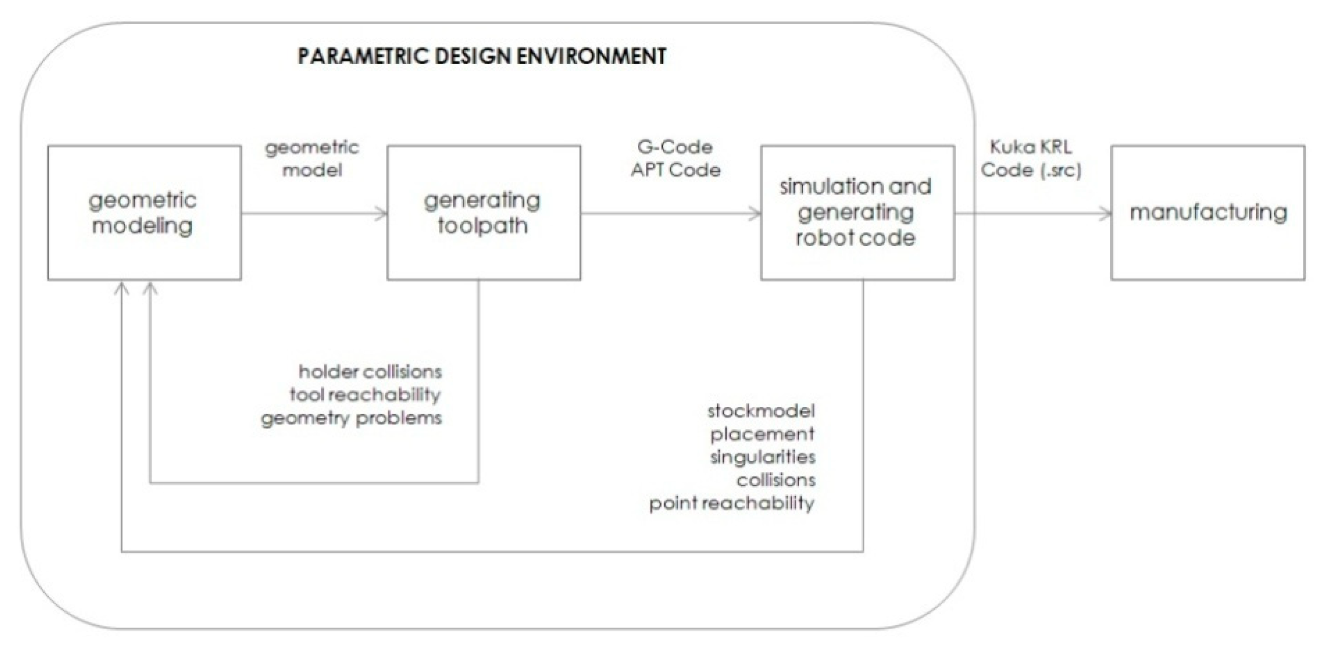
Using industrial robots in digital fabrication is called robotic fabrication. In robotic-fabrication applications, the industrial robot offline programming workflow consists of four steps; modeling, toolpath generation, post-process with simulation, and fabrication [
23]. In the modeling step, a geometric model is created with computer-aided-modeling (CAD) tools. The toolpath-generation step calculates the path that the cutting tools will follow during the manufacturing of the model with CNC (computer-numerical-control) machines. Computer-aided-manufacturing (CAM) software tools are used in the toolpath-generation step. The generated toolpath code is generally in G-code or APT-code (automatically-programmed-tool) format. The toolpath generated for CNC machines must be post-processed into robot code to be used with industrial robots. While post-processing the toolpath and creating the robot code, it is important to determine the collision risks that the industrial robot may encounter during the fabrication process, to detect errors such as accessibility, exceeding axis limits, and singularity, and to avoid collisions and errors. For these reasons, it is necessary to simulate the industrial robot and its environment before production. These tasks are done in the simulation and robot-code-generation steps. The last step of the robotic-fabrication process is loading the robot code to the industrial robot and running the robot code. This offline programming workflow is linear. Users should follow these four steps in order. If the user wants to make changes in any of the previous steps, the user must repeat other steps that follow. The user can only move on to the next step after completing the previous step.
2.2. Parametric Robot-Control Tools
Another method of using industrial robots in robotic-fabrication applications is to create industrial robot programs with parametric-modeling tools. Kuka|PRC [
23,
24] and ABB HAL [
25] plug-ins developed for the Grasshopper3D parametric-design program can be given as examples of this method. With parametric robot-control tools, users can complete modeling, toolpath generating, simulation, and robot code post-processing tasks with parametric-modeling tools. In this way, if any change is made in any of the previous steps, the following steps are automatically updated instantly, and users do not need to repeat other steps that follow. Design-to-production workflow can be managed more flexibly and users can change any desired step with parameters. That both design and robotic fabrication can be controlled by parameters has enabled mass customization [
23].
Figure 1 shows the robotic fabrication workflow in the parametric-design environment.
3. Materials and Methods
In this study, a method for creating parametric design and robotic fabrication steps in a mixed-reality environment is proposed. Users can control parametric design and robotic-fabrication processes with parameters in the mixed-reality environment. Users can also interact physically and virtually with the design and fabrication environment and make changes at the time of design and fabrication and all the following steps are updated without the need for user intervention. Users can get real-time design and production feedback in the mixed-reality environment. The robotic-fabrication process can continue with human–robot collaboration. In this way, the whole process from geometric modeling to robotic fabrication can be controlled by hand gestures. Simulation images can be viewed as holographic content by adding on the images of the real production environment. Multiple users can coexist in the same holographic environment at the same time and multiple users can interact with the holographic contents in the same parametric design and robotic-fabrication process. In
Figure 2, parametric design and robotic fabrication within a mixed-reality-environment workflow can be seen.
The second generation HoloLens mixed-reality device was used in the study. In the HoloLens mixed-reality device, the holographic content is superimposed on top of the real-world images. The mixed-reality device creates holograms of light and sound objects that look like real objects around us. Holograms can respond to the user’s gaze, gestures, and voice commands. Holograms are created in a holographic virtual world and on the lens in front of the wearer’s eye. The hologram disappears when the angle of view is changed, but if the perspective is directed back to the scene where the object is located, the hologram is displayed again in its real-world location. Users can interact with both real-world objects and the holographic contents in real-time. The mixed-reality device recognizes the boundaries of the real-world environment with its sensors and updates the holographic contents with these boundaries. The mixed-reality device can detect the positions of objects in the real-world, which makes reality perception richer. That user can control holographic content by hand gestures in the mixed-reality environment, strengthens reality perception. In addition, mixed-reality devices allow multiple users to share the same holographic environment and multiple users can interact with the same holographic contents at the same time [
26].
In
Figure 3, the roles of the mixed-reality tool, the industrial robot, and the parametric-design software in the proposed workflow can be seen.
The initial step of the proposed method is to create the parametric-model definition. Grasshopper3d 1.0 software was used as the parametric-design tool in this study. Grasshopper3d parametric-modeling tool runs inside Rhino3d 7.2 modeling software as a plugin. After the model is defined in the parametric-design program, the user can make changes to the parameters of the model in the mixed-reality environment. The user can monitor the changes in the model in the mixed-reality environment while modifying the parameters of the model.
After the parametric modeling step, the toolpath that will be used to manufacture the model is calculated with the parametric-modeling tool. The generated toolpath must be post-processed and transformed into robot code in order to be used with the industrial robot. At this point, it is necessary to determine the collision risks that the industrial robot may encounter during production, to detect errors such as accessibility, exceeding axis limits, and singularity, and to avoid collisions and to fix errors. In order to do this, robotic fabrication simulation is created in the mixed-reality environment. The parameters required for the toolpath to be post-processed into robot code are determined by the user in the mixed-reality environment. Changes made to parameters can be monitored instantly in the holographic simulation created in the mixed-reality environment.
The robot code is sent to the industrial robot using the communication between the parametric-design program and the industrial robot. After receiving the robot code, the industrial robot executes the commands. If the user makes changes to the model parameters or robot code post-process parameters within the mixed-reality environment at the time of production, the following steps are automatically updated and the production process continues without interruption.
In order to create the proposed method, instant communication between the parametric-design program, the mixed-reality device, and the industrial robot control unit is required. Parameters of the model, geometry information of the model, robot code post-process parameters, and robot code data can be transmitted through instant communication.
Figure 4 shows the communication diagram between the parametric-design software, the mixed-reality device, and the industrial robot.
3.1. Communication and Simulation
In our study, five distinct software-development tasks were completed in order to create instant communication between the parametric modeling software, the mixed-reality device, and the industrial robot control unit, and to simulate the industrial robot in the mixed-reality device.
Running Grasshopper3d in “Headless Mode” and developing the REST API Server software for Grasshopper3d parametric modeling software;
Developing the REST API Client software in Unity Game Engine for HoloLens 2 Mixed-Reality Device;
Developing the inverse kinematic solver for 6-axis industrial robots with a spherical wrist in Unity Game Engine;
Developing the TCP Socket Server software for Kuka Robot Control Unit (KRC);
Developing TCP Socket Client Software in Unity Game Engine for HoloLens 2 Mixed-Reality device and Grasshopper3d parametric modeling software.
3.1.1. REST API Server for Grasshopper3d Parametric Modeling Software
By default, the Grasshopper3d parametric-modeling tool is not accessible from other devices, such as a mobile device or a mixed-reality headset. The Grasshopper3d parametric-modeling tool runs only on the computer on which the program is installed. In our study, we developed an application programming interface (API), which enables users to access the Grasshopper 3d parametric-modeling tool via HTTP interface. Users can send input parameters with HTTP requests from the mixed-reality headset. The input parameters are calculated inside the Grasshoper3d parametric-modeling tool, and the results are returned with HTTP response to the program installed on the mixed-reality device, in near real-time.
REST API Server software has been developed for the Grasshopper3d program to instantly communicate with the mixed-reality device. Under REST architecture, the client and server can only interact in one way: the client sends a request to the server, and then the server sends a response back to the client. Servers cannot make requests and clients cannot respond. All interactions are initiated by the client. Incoming requests and outgoing responses are JSON formatted. JSON data packages are easy to parse and easy to generate with programming languages. C# programming language, .NET Framework, and NancyFX lightweight web framework [
27] are preferred to develop the REST API Server.
In order for Grasshopper3d to respond to incoming requests, the Rhino.Inside feature that comes with the 7th version of the Rhino3d program has been extended. The Rhino.Inside is an open-source project that enables Rhino3d and Grasshopper3d programs to be used inside other programs running on the same computer such as Autodesk Revit, Autodesk AutoCAD, and Unity. The Rhino.Inside technology allows Rhino and Grasshopper to be embedded within other products. It may be possible starting Rhino and Grasshopper as an add-in another product, to call directly into the host’s native APIs from a Grasshopper or Rhino plug-in, to access Rhino’s APIs through the host application; grasshopper definitions can be opened and previewed in Rhino within the same process as the parent, and objects can be natively created by Rhino or Grasshopper within the parent product [
28].
In this study, primitive data types such as boolean, integer, double, string, and RhinoCommon SDK [
29] data types including arc, box, circle, curve, line, mesh, mesh face, plane, point, rectangle, and vector were implemented and can be used as both input and output parameters for REST API Server communication requests and responses.
REST API Server software can be accessed through different client devices including a web browser, a mobile device, or other software.
Figure 5 shows a sample Grasshopper3d definition and the generated result with parameters and
Figure 6 shows HTTP request input parameters and the calculated result as HTTP response output parameters. In
Figure 6, while receiving the HTTP request and returning the HTTP response, Grasshopper3d program runs in headless mode in the background.
3.1.2. REST API Client for HoloLens 2 Mixed-Reality Device
In the next step of the study, the REST API client software that sends requests to the REST API Server and receives the responses was developed for the mixed-reality device. The Unity Game Engine and Mixed-Reality Toolkit (MRTK) [
30] were used to develop the REST API client software for the mixed-reality device.
The Unity Game Engine has the right-handed Y-Up coordinate system whereas Grasshopper3d has the left-handed Z-Up coordinate system. Grasshopper primitive and RhinoCommon SDK [
29] data types retrieved from REST API Server program are converted to Unity data types and Unity coordinate system. In this study, arc, boolean, box, circle, curve, integer, line, mesh, float, plane, point, rectangle, string, and vector data types were supported in Unity Game Engine and Mixed-Reality Toolkit.
Figure 7 shows the REST API Client program running inside Unity Game Engine. If the user changes
size,
height,
box number, or
rotation angle parameters, the Unity Game Engine sends these parameters to Grasshopper3d modeling tool via HTTP request and gets the calculated result as an HTTP response. In
Figure 7, the boxes are generated inside Grasshopper3d parametric-design tool with the parameters sent over HTTP communication.
3.1.3. Inverse Kinematic Solver for 6-Axis Industrial Robots
In this study, an inverse kinematic solver of 6R serial industrial robot manipulators with an Euler wrist was developed for the Unity Game Engine, which has the right-handed Y-Up coordinate system. For an industrial robot, inverse kinematics refers to solving angular values of its joints to reach a given desired position and orientation value. In this way, a 6-six-axis industrial robot with a spherical wrist can be simulated in mixed-reality environment. Simulating the industrial robot is important for detecting singularities, reachability errors, exceeding angular limits, and collision detection.
Figure 8 shows Kuka KR210 simulation inside the Unity Game Engine.
3.1.4. TCP Socket Server Software for Kuka Robot Control Unit (KRC)
In the next step, TCP Socket Server software was developed for the industrial robot. Unlike REST API communication, TCP Socket communication is a two-way communication. Using TCP Socket communication, the industrial robot receives robot commands, executes, and sends the result back. Execution time is needed between receiving the robot commands and sending the results back.
Kuka KR210 industrial robot was used in this study. Since the Windows 95 operating system was installed on the VKRC2 robot control unit of the KR210 industrial robot, Visual Basic 6.0 programming language was used while developing the TCP Socket Server software.
Figure 9 shows TCP Socket Server software screenshot taken from Kuka Control Robot Unit (VKRC2).
3.1.5. TCP Socket Client Software for HoloLens 2 Mixed-Reality Device and Grasshopper3d Parametric Modeling Software
In this study, TCP Socket client software was developed for the HoloLens 2 Mixed-Reality device and the Grasshopper3d parametric-modeling tool application programming interface. In this way, the industrial robot receives robot commands, executes, and sends reports to the mixed-reality device and the Grasshopper3d parametric modeling software runs in headless mode.
3.2. Shape Grammars
Shape Grammars were first invented by George Stiny and James Gips in their 1972 article
Shape Grammars and the Generative Specification of Painting and Sculpture [
31]. Shape grammars are rule systems of transformational shape rules that describe the design of a shape. A shape rule defines how an existing (part of a) shape can be transformed [
32].
Shape grammars consist of an initial shape which can be a point, line, or polygon; a start rule; transformation rules, which are usually applied recursively; and a termination rule.
Figure 10 shows the initial shape, shape rules for a standard shape grammar, and the results generated by applying the transformation rules recursively [
32].
4. Results
In order to test the proposed method in this study, a robotic-fabrication-workshop test environment is created. The proposed method was tested on a design product, which was defined with the shape-grammar method using parametric-modeling tools. Natural stone material was chosen to test the proposed method in robotic fabrication.
In the study, the standard shape-grammar method was used to generate the three-dimensional design product in parametric-design software. Triangular areas were converted into triangular pyramids. The locations of the apex points of these triangular pyramids were calculated with median-weight, corner-weight, and height parameters.
In a triangle defined by the A, B, and C corner points, the location of the D point was calculated with the
corner-weight parameter between the B and C points. Then, the location of the
apex point was calculated with the
median-weight parameter between A and D points and the
height parameter.
Figure 11 shows the
apex point and the
corner-weight and
median-weight parameters.
Figure 12 shows the results generated by applying the transformation rules and the termination rule.
Figure 13 shows the results generated by applying different transformation rules defined with
corner-weight,
median-weight,
height,
rotation, and
repeat parameters, and different termination rules.
In the study, a natural stone robotic fabrication workshop was created to test the proposed method.
Figure 14 shows that the user can change the parameters of parametric-design and robotic-fabrication tasks within the mixed-reality environment and robotic fabrication can continue uninterrupted.
Figure 15 shows that the user can access and change the parametric design and robotic-fabrication parameters using the mixed-reality device.
Figure 16 shows that the user can change design and production parameters, and gets instant visual and spatial feedback of the design and production alternatives while robotic fabrication continues. The following tasks in the workflow do not need to be repeated in the production phase.
The user changes the parameters of the shape-grammar transformation rule at each iteration.
Figure 17 shows the design product that was manufactured with the proposed method. The results of each iteration, generated by applying different transformation rules, defined with
corner-weight,
median-weight,
height, and
rotation parameters, and the result of the termination rule at the last iteration can be seen in
Figure 17.
Figure 18 shows the production results of design products defined with the shape-grammar method. There are nine different natural stone products in the figure. Eight production results were manufactured with existing methods using parametric-modeling tools. The product located at the center was manufactured with the proposed method, and different transformation rules (
corner weight,
median weight,
height, and
rotation) were applied to this product at each iteration, while production continued. Thus, transformation rules were irregular, unlike the other eight pieces in the figure.
The design and robotic-fabrication processes of the proposed method are shown. The proposed method and the existing methods are compared and discussed in terms of mass-customization, the design-to-production process, scalability, machine time, process, and material efficiency, human–robot collaboration, production-immanent modeling, interactive design, and interactive robotic-fabrication possibilities. In
Table 1, the robotic fabrication offline programming method, programming with parametric robot control tools, and the proposed method are compared in terms of design and robotic-fabrication possibilities based on the observations obtained from the test results.
5. Discussion and Future Work
The proposed method and other existing methods are compared and discussed in terms of design and robotic-fabrication possibilities based on the observations obtained from the test results. With the proposed method, the user can explore design and production alternatives within the mixed-reality environment by changing the parameters, and gets instant visual and spatial feedback on the design and production alternatives. With changing the parameters, the design product as well as the robot code required for the production of these parts are updated, and the robot code is uploaded to the industrial robot instantly. These tasks are completed in one unified step and the design-to-production process is shortened since the user does not need to do manual interventions in the intermediate steps. Robotic fabrication can continue uninterrupted with human–robot collaboration.
Different from existing robotic fabrication workflows, with the proposed method, users can change the design and fabrication parameters while robotic fabrication continues. The design and manufacturing processes are combined and blended, thus users can complete the design and manufacturing tasks within one unified framework. Unlike other existing robotic fabrication methods, the proposed method provides interactive robotic-fabrication possibilities in addition to interactive parametric-design possibilities.
In existing robotic-fabrication workflows, parametric design and robotic fabrication are discrete operations. If users want to make changes in the design phase, or production phase the robot code generated on the computer needs to be transferred and uploaded again to the robot control unit because the outputs of the previous steps are used as inputs for the next steps. Users may need to work with different software CAD/CAM tools and repeat these steps on both the computer and the robot control unit. Unlike other methods, in the proposed method, parametric-design and robotic-fabrication possibilities are offered to the user as one unified step within the mixed-reality environment and the time required to complete the design and manufacturing process is shortened. In addition, with this improved workflow, industrial robot-programming knowledge is not required to complete robotic-fabrication tasks.
Another advantage of the proposed method is that users can use stock material resources more effectively. The digital twin of both parametric design and robotic fabrication is created and users can monitor the changes in both stock materials and design products in the mixed-reality environment while robotic fabrication continues. Thus, users can use stock material resources more effectively with the proposed method.
The proposed method allows using parametric-modeling tools within the mixed-reality environment in both the design and production phases of robotic fabrication. This allows users to perform robotic fabrication interactively. In this interactive robotic fabrication, users can both use the design and production possibilities offered by parametric-modeling tools such as mass-customization in the production phase, as well as access design opportunities such as interactive design, emergent design, and generative design in the design phase. However, the usage of the proposed method is limited with parametric-modeling tools.
In addition, the proposed method allows multiple users to co-exist in the same mixed-reality environment and interact with real and virtual objects at the same time. Thus, parametric design and robotic fabrication can be performed by multiple users and with multiple industrial robots. Design and production alternatives can be explored by multiple users. In this respect, the method can be scaled in terms of the number of users, the number of industrial robots used in production, and human–robot collaboration.
There are future studies to be done on exploring the potential of the proposed method improved with computer vision and machine-learning technologies. For future studies, the research team focused on improving the proposed method with image-tracking and object- tracking technologies provided by augmented reality development toolkits [
33,
34].


