Abstract
Ordinary mixers can hardly meet the requirements in terahertz (THz) communications due to the low-power and expensive THz sources. Sensitive harmonic mixers have been widely studied to avoid this problem, owing to the fact that the higher the number of harmonics, the lower the local oscillator (LO) frequency, and the lower the cost. High-Tc superconducting (HTS) Josephson junction (JJ) mixers are performing candidates for THz receiver frontends because of the advantages of excellent sensitivity, wide bandwidth, high harmonic number and low LO power requirement. However, the normal-state resistance of HTS JJ is so low that traditional antennas are difficult to match it. In other words, it is quite a challenge to match the input impedance to a low input impedance for traditional antennas, especially for antennas fed by coplanar striplines (CPSs). In this work, based on the structure of bowtie, two types of stub tuners were integrated to decrease the impedance of the bowtie antenna so as to improve the coupling efficiency between the traditional bowtie antenna and the JJ. Furthermore, HTS YBa2Cu3O7-δ (YBCO) JJ harmonic mixers coupled with the proposed structures and fed by CPSs are fabricated and measured. The measurements show that the JJ mixer coupled with a pair of open-end stubs of the bowtie antenna achieves up to 88 harmonics, with a conversion efficiency of −69.6 dB. In contrast, the JJ mixer coupled with a pair of lumped-element stubs of the bowtie antenna only attains to 30 harmonics, with a conversion efficiency of −73.4 dB. Additional numerical simulations indicate that the coupling efficiency is enhanced when the complex impedance of the antenna is explicitly considered. Compared with other coupled traditional antennas, the JJ mixer with bowtie antenna has the largest harmonic number. This work paves the way for the future application of low-frequency and low-cost LO for THz communications.
1. Introduction
Thanks to the considerable absolute bandwidth, terahertz (THz) communication promises to have the advantages of large capacity, high transmission rate, high security, strong directivity and good penetration. However, due to the serious atmospheric attenuation in THz bands [1], the effective detection of ultrasensitive THz receivers is highly demanded. Due to the limitation of low power and high cost of THz source, harmonic mixer is more popular than fundamental mixer. The higher the number of harmonics, the lower the frequency and cost of the local oscillator (LO).
Semiconductor-based THz heterodyne receivers, generally operating at room temperature, have been widely developed using Schottky barrier diodes [2], high-electron-mobility transistors [3], complementary metal-oxide-semiconductor [4] and silicon-germanium [5] technologies. However, the maximum harmonic number up to 20 is from the Schottky barrier diode produced by Virginia Diodes, Inc. (VDI) [6]. Nowadays, high-Tc superconducting (HTS) YBa2Cu3O7-δ (YBCO) Josephson junction (JJ) is becoming the most attractive harmonic mixer for THz heterodyne receiver, caused by the advantages of excellent sensitivity, wide bandwidth, high harmonic number and low LO power requirement [7]. Broadband antennas with complementary structure have been extensively used in superconducting mixers to enhance the THz signal coupling, such as log-periodic and log-spiral antennas [8]. However, the impedances of this kind of antennas are very high (approximately 188.5 Ω with self-complementary structure in free space), while the normal-state resistances of the YBCO JJs are only several ohms, still resulting in the low coupling efficiencies between antennas and JJs. Thus, the maximum harmonic number cannot be improved in the mixing because of the impedance mismatch. Recently, many works have been reported to enhance the mixing performance of YBCO JJ mixers, including the harmonic number in the mixing [9,10,11]. It shows that the maximum harmonic number from YBCO step-edge JJ is around 30, a bit higher than that with a semiconducting THz mixer. Thus, the enhancement of the maximum harmonic number of the YBCO JJ mixer urgently needs to be explored for THz communications.
In reported traditional antennas, slot antennas [12,13,14,15] were the main choices to match the impedance of JJ, such as double-slot antenna [16] and ring-slot antenna [17,18]. However, these kinds of antennas have to be fed by coplanar waveguide (CPW), meaning the shape of the ground has to be changed during the impedance matching. The impedance matching to a low-input impedance based on traditional antennas with coplanar striplines (CPSs) feeding for a JJ mixer is little reported. The influence of ground shape on the antenna impedance would no longer be considered if the differential CPSs were adopted. The bowtie structure was first proposed by George et al. [19] and applied to many THz detectors [20,21,22,23,24]. Because of the simple structure and low cost, it is a good choice to match the impedance with YBCO JJ mixer and feed it by CPSs. Traditional bowtie antennas often have impedances as high as hundreds of ohms.
In this paper, we adopt two types of stub tuners on bowtie antennas to reduce antenna impedances. The performance of YBCO bicrystal JJ harmonic mixers coupled with these two antennas and fed by CPSs are reported, respectively. Since one of the THz windows is located at 0.21 THz [1], we study the maximum harmonic number of mixers at 0.21 THz. Up to the 88th harmonic has been measured in the mixing when one mixer is coupled with a pair of open-end stubs of the bowtie antenna, while the other one, which coupled with a pair of lumped-element stubs of the bowtie antenna, has a maximum harmonic number of 30. Later, numerical simulations are carried out to analyze the reasons for different performance.
2. Materials and Methods
2.1. Silicon Lens for Eliminating Thick Substrate Modes
THz antenna on thick dielectric suffers power loss because of substrate modes, shown in Figure 1a. More than 90% of the radiated power is trapped in the dielectric [25]. If the substrate thickness can be made infinite, the loss in the substrate mode can be eliminated. Additionally, the infinite dielectric can be synthesized by a lens with the same dielectric constant attached to the antenna substrate [26]. The substrate lens can be hemispherical, hyper-hemispherical and elliptical, seen in Figure 1b–d. As hyper-hemispherical lens [27,28] is widely used and easier to design, we focus on the hyper-hemispherical lens in our study.
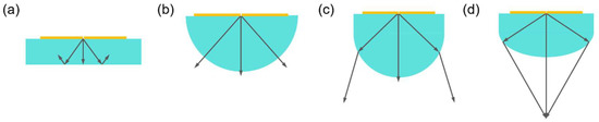
Figure 1.
Antenna with (a) no substrate lens, (b) hemispherical lens, (c) hyper-hemisphere lens and (d) elliptical lens.
If a dielectric hemisphere is attached to the back of the substrate with the same relative permittivity as the interface between them, there will be no refraction or reflection. All radiated rays will directly strike the circular surface of the hemisphere without any disturbance, and there will be only loss due to the reflection loss [29]. This type of lens is called hemispherical lens, shown in Figure 1b. By introducing a matching layer of quarter wavelength, this loss can be eliminated or minimized, the layer is called anti-reflection (AR) coating. If the hemisphere lens is extended by adding a cylinder with the same diameter and attached with the antenna then it is called the hyper-hemispherical lens, shown in Figure 1c. The thickness of this cylinder is called the extension length of the lens.
As the superconducting YBCO film was deposited on a bicrystal magnesium oxide (MgO) substrate with the dielectric constant of 9.6, the high-resistivity, float-zone (HRFZ) silicon (Si), whose dielectric constant of 11.9 is close to that of MgO, is chosen to prepare the hyper-hemispherical lens. Furthermore, the loss tangent of HRFZ Si can be ignored in THz band.
Loss tangent is calculated according to the Formula (1) [30], where is the circular frequency, is the dielectric constant of vacuum (8.85 ), is the relative permittivity of Si (11.9), and is the specific resistance. For example, loss tangent of HRFZ Si with a resistivity of 10 kΩ cm at 1 THz is 1.5 .
The hyper-hemispherical lens can be designed by Equation (2) [31], where is the length of the extension, is the radius of the hemisphere and is the refractive index of the lens, which is equal to . In the literature [26], by changing the diameter of the hyper-hemispherical lens from 4 mm to 9 mm, the directivity increases with the increase in diameter in the low-frequency band of THz. Thus, we make the radius of the hyper-hemispherical lens of 4.5 mm. According to Equation (2), the extension length of the lens should be 1.3 mm. However, due to the thickness of the integrated chip being 0.5 mm or 0.6 mm, the extended length of the customized hyper-hemispherical lens is 0.7 mm.
AR coating of the substrate lens should have a thickness of a quarter wavelength (/4), and the refractive index of the coating material meets the Formula (3) [26], where , and are the refractive indexes of AR coating, Si and the air, respectively. Thus, the thickness of the AR coating is 357 μm at 0.21 THz, and equals to 1.86.
As the beam pattern is mainly controlled by the lens, a simple bowtie structure (Antenna 1 below) on a hyper-hemispherical lens with above parameters ( = 11.9, = 4.5 mm, = 1.3 mm, = 1.86, /4 = 357 μm at 0.21 THz) was modeled and simulated to get the directivity in the electromagnetic simulator Computer Simulation Technology (CST) Microwave Studio (MWS). In order to save simulation time, the number of mesh cells across stubs is 3 or 4 in x or y coordinate direction. A discrete port with 20 Ω is set to feed the bowtie antenna. Time domain solver based on finite integration technique is chosen with the accuracy set of −50 dB. As a result, the model and the radiation pattern are created and shown in Figure 2. The green-colored shape is the AR coating with the thickness of 357 μm and the relative permittivity of 3.45. The simulation shows that the directivity of the Si hyper-hemispherical lens with the above parameters attains 21.48 dBi at 0.21 THz.
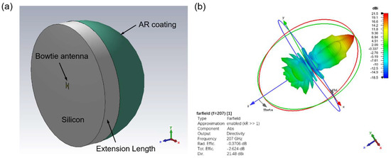
Figure 2.
(a) Model of the hyper-hemispherical lens with bowtie feed in CST MWS. (b) Radiation pattern of the hyper-hemispherical lens with the radius of 4.5 mm at around 0.21 THz.
2.2. On-Chip Layout Design
The mixer chip often contains direct current (DC) bias lines, electrodes and so on. Figure 3a,b show the presented geometry of the on-chip layout. Stub tuners are loaded at different positions on bowtie antennas, integrated with YBCO bicrystal JJs. The arm length and width of the bowtie are 135 μm and 515 μm, respectively. A pair of stubs with length of = 30 μm, width of = 30 μm and an interval of 10 μm, acting as lumped elements [32], are put in the middle of the bowtie, which forms as Antenna 1. Another pair of stubs with length of = 225 μm, width of = 10 μm and an interval of 10 μm, placed vertically in the middle of another bowtie, have open ends [33]. Thus it forms as Antenna 2. In addition, electrodes, DC bias lines, and choke filters [34] are integrated on a MgO substrate with the dielectric constant of 9.6. The DC bias lines are connected to the part of bowtie with the weakest current distribution to prevent alternating current (AC) power leakage from the antenna. Choke filter with a bandgap structure [35] is applied on the DC bias lines to avoid AC power leakage to the CPSs. The optimized parameters at 0.21THz by CST MWS are as follows: = 32 μm, = 246 μm, = 15 μm, = 165 m, = 90 μm, = 90 μm and = 135 μm. The length of each section of choke filter is ~/4 [36] with
where is the wavelength in free space, and is the dielectric constant of the substrate. As seen in Figure 3c, currents leaked from both antennas are effectively blocked by choke filters, respectively. At the other ends of CPSs, four electrodes are applied in the four-terminal measurement to exclude the influence of contact resistance.
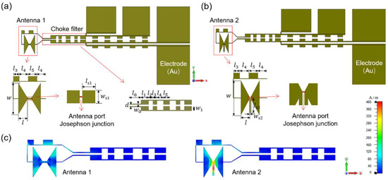
Figure 3.
(a,b) Geometry of the on-chip layout based on YBCO bicrystal JJ THz mixer (structure parameters: = 135 μm, = 515 μm, = 30 μm, = 30 μm, = 32 μm, = 246 μm, = 15 μm, = 165 μm, = 90 μm, = 90 μm, = 135 μm), = 225 μm, = 10 μm. (c) Current distribution on the antennas and the choke filters at 0.21 THz.
2.3. Fabrication and Experimental Setup
The 80 nm-thick YBCO film with a 20 nm in situ Au film on top was deposited on the MgO substrate with a bicrystal misorientation angle of 24° and the thickness of 0.5 mm by pulsed laser deposition. The critical current density Jc of the YBCO film is 2.5 mA cm−2, and the critical temperature Tc is 85.7 K. HTS YBCO JJ THz mixers were patterned by a standard photolithography and Ar-ion beam etching technologies. The 2 μm-wide YBCO strips across the grain boundary (GB) form JJs were embedded into two antennas, respectively, as seen in the zoomed photo of Figure 4a. Then, the mixer chip was packaged into a sample holder. A Si hyper-hemispherical lens with parameters of = 11.9, = 4.5 mm and the extension length of 0.7 mm is fixed on the back of the mixer chip with cryogenic glue to focus the THz signal on the chip surface where JJ is located. The DC bias lines on the mixer chip are connected to the DC bias pins on the holder through gold wires and silver epoxy. Intermediate frequency (IF) output shares the same path with DC bias lines and is isolated by two capacitors. A radio-frequency (RF) filter module consists of resistors and capacitors and is applied to the DC bias pins to isolate DC and RF signals. LO signal is radiated out by a 1.95 cm-long monopole antenna, 0.8 cm above the holder mounted in the Gifford–McMahon (GM) cryocooler, shown in Figure 4b.
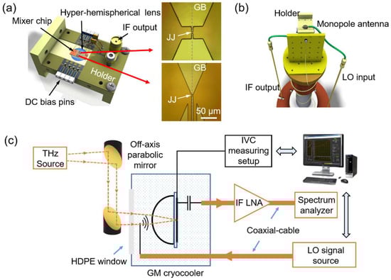
Figure 4.
(a) Mixer chip on a sample holder with packaged modules. (b) Three-dimensional view of the monopole antenna at LO input in a GM cryocooler. (c) Schematic diagram of the measurement setup for harmonic mixing.
Measurements are carried out in a GM cryocooler at a bath temperature of about 4.5 K. The schematic diagram of the measuring setup for harmonic mixing is shown in Figure 4c. THz signal is generated from commercial VDI-Tx-S140 manufactured by VDI. Two off-axis parabolic mirrors are applied in the quasi-optical system to focus THz radiation on the Si hyper-hemispherical lens. The LO pump is produced from a microwave analog signal generator Agilent N5183A MXG and radiated through a frequency-dependent monopole antenna. Additionally, the radiation efficiency of the monopole antenna has been calibrated by a vector network analyzer. HP 8447D 011 Dual Amplifier, which has a gain of about 50 dB in the 0.1–1300 MHz frequency band, is used to amplify the down-converted IF output signal, finally recorded in an Advantest R4131D spectrum analyzer. In addition, a homemade current source and an automatic acquisition system of I–V characteristics (IVCs) are applied in the measurements.
3. Measurement Results
3.1. DC Characteristics and Coupling Power Estimation
Figure 5 shows the measured and simulated IVCs of the JJ mixers coupled with different antennas with and without the ~0.21 THz radiation. The Mixer 1 coupled with Antenna 1 (bowtie loaded with a pair of lumped-element stubs) has a critical current (Ic) of 550 μA and a normal-state resistance (Rn) of 0.78 Ω. The Mixer 2 coupled with Antenna 2 (bowtie loaded with a pair of open-end stubs) has a Ic of 900 μA and a Rn of 1 Ω. When mixers are pumped by a ~0.21 THz signal, are suppressed to ~110 A and ~275 μA, respectively, but Shapiro steps [37] are located at the same voltages. Obviously, the voltages where the Shapiro steps are located are related to the incident frequency fTHz, consistent with the Josephson voltage–frequency relationship
where is an integer, and is the magnetic flux quantum [38],
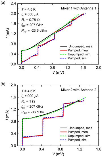
Figure 5.
(a) Measured and simulated DC IVCs of the JJ Mixer 1 coupled with Antenna 1: bowtie loaded by a pair of lumped-element stubs under a 0.21 THz signal radiation or not at the bath temperature about 4.5 K. (b) Measured and simulated DC IVCs of the JJ Mixer 2 coupled with Antenna 2: bowtie loaded by a pair of open-end stubs under a 0.21 THz signal radiation or not at the bath temperature about 4.5 K.
As the first Shapiro steps are located at 0.429 mV, the fTHz is estimated at 0.207 THz. According to the measured DC IVCs and resistively shunted junction (RSJ) model [39], the THz power PTHz, which has been coupled into the junctions, can be obtained through numerical simulation by MATLAB software. The circuit equation for this model is
where the phase difference is related to the voltage by the Josephson relation
In our experiment, = 0 for JJ mixer is performed for zero-bias operation which means that there is no DC bias supply, and thus, there is no heating effect or shot noise in the junction due to DC bias current [40]. and are THz current in the junction and THz pump frequency here. Thus, the THz power PTHz coupled into the junction is
The fourth-order Runge Kutta algorithm is used to numerically solve the first-order differential equation with a sinusoidal function. When the simulated DC IVCs matches the measured well, PTHz of mixers coupled with Antenna 1 and Antenna 2 are −23.6 dBm and −36 dBm, respectively. Minor errorbetween the simulated and the measured DC IVCs at ~0.4 mV in Figure 5a may be caused by a capacitance in the junction.
3.2. Harmonic Mixing Performance
For a harmonic mixer,
where n is the harmonic number, especially
as in Ref. [17], for the down-conversion mixer in our experiment. In order to detect the maximum harmonic number, we kept LO power PLO at a higher level of 11 dBm, and adjusted the frequency fLO from 10 GHz with a decreasing step of 0.002 GHz. Finally, as recorded in Figure 6a, when the mixer was coupled with Antenna 1, the power of IF output PIF was −47 dBm at 944 MHz, which was generated from the maximum harmonic number of 30 that we could detect in the mixing between fTHz = 0.207 THz and fLO = 6.932 GHz. If we decreased the PLO to 5 dBm, the PIF of −44.6 dBm at 1017 MHz was recorded in Figure 6b, with the maximum harmonic number decreasing to 22. On the other hand, when the mixer was coupled with Antenna 2, the maximum harmonic number attained in the mixing was 88, with the fLO of 2.36 GHz and the PLO as low as 4 dBm, shown in Figure 6c. Thus, under a similar level of LO pumping, the maximum harmonic number from Mixer 2 is much higher than that from Mixer 1.
fIF = |fTHz ± nfLO|,
fIF = |fTHz − nfLO|
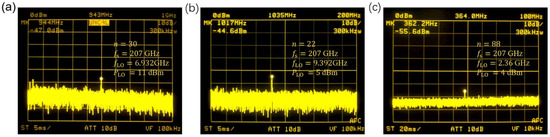
Figure 6.
Measured frequency spectra of the IF output from the JJ (a) Mixer 1 coupled with Antenna 1: bowtie loaded by lumped-element stubs when fLO = 6.932 GHz, PLO = 11 dBm, n = 30, and (b) when fLO = 9.392 GHz, PLO = 5 dBm, n = 22; (c) Mixer 2 coupled with Antenna 2: bowtie loaded by open-end stubs when fLO = 2.36 GHz, PLO = 4 dBm, and n = 88 under a 0.207 THz radiation.
The conversion efficiency of the HTS JJ THz mixers can be calculated on Equation (12) [10], where GIF is IF amplifier gain, which is around 50 dB in our experiment. PIF can be read from the spectrum analyzer directly. Additionally, PTHz has been calculated through numerical simulation. Thus, the conversion efficiency of the mixer coupled with Antenna 1 is −73.4 dB in the 30th harmonic mixing, while the other one, coupled with Antenna 2, is −69.6 dB in the 88th harmonic mixing.
The mixing parameters of HTS JJ mixers coupled with different traditional antennas with the detected maximum harmonic numbers are listed in Table 1. Coupled with traditional antennas, the JJ with bowtie antenna achieves the highest harmonics. Generally, the conversion efficiency increases with the decrease in harmonic number. However, the JJ mixer coupled with the bowtie antenna (described herein) maintains the similar value of conversion efficiency while the harmonic number is nearly twice of that with a log-periodic antenna. The application of stubs on bowtie antenna has been proven to improve the performance of HTS JJ mixer.

Table 1.
Performance comparison of HTS JJ mixers coupled with different traditional antennas with the detected maximum harmonic numbers.
4. Discussion
The mixer coupled with Antenna 2 has a larger harmonic number than that of the other mixer when coupled with Antenna 1. Even more, the mixer coupled with Antenna 2 shows a better mixing performance with the conversion efficiency of −69.6 dB in the 88th harmonic mixing, while the other, coupled with Antenna 1, only has a maximum harmonic number of 30 with the conversion efficiency of −73.4 dB. To explore the reasons, we simulated these two microwave circuit models of mixer chips with attached customized Si hyper-hemispherical lens by CST MWS, displayed in Figure 7a. Because the size of the hyper-hemispherical lens is electrically large relative to the structure in the chip, the AR coating is omitted in the model. Simulated input impedances where HTS JJs locate on the mixer chip attached to a Si hyper-hemispherical lens are shown in Figure 7b. The impedance is 74 − j64 Ω when the mixer coupled with Antenna 1. However, the other impedance is 6 + j36 Ω when the mixer coupled with Antenna 2. Giving an impedance Zm of the JJ mixer, the coupling efficiency of the antenna can be computed with standard antenna theory as
in [42], where Za is the impedance of the antenna. Assuming Zm ≈ Rn [16], when the mixer with the Rn of 0.78 Ω (Mixer 1) is coupled with Antenna 1, the ηc is only 0.79%. However, when the other mixer with the Rn of 1 Ω (Mixer 2) coupled with Antenna 2, the ηc is 2.7%. Therefore, the coupling efficiency of Mixer 2 is higher than that of Mixer 1. Furthermore, looking back at the surface electric current distribution in Figure 3c, the current where JJ is located in Antenna 2 is stronger than that in Antenna 1. More energy has been transmitted into the junction by Antenna 2. Thus, Mixer 2 coupled with Antenna 2 has a better performance and larger harmonic number.
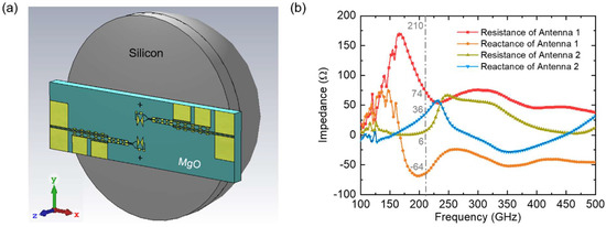
Figure 7.
(a) Model of the actual mixer chip attached to a Si hyper-hemispherical lens in CST MWS. (b) Simulated input impedances where HTS JJs locate in (a) model.
If the antenna matches to the superconducting mixer impedance (a very low normal-state resistance), the radiation efficiency of the antenna will be very low because of the low resistance. Thus, further work can focus on other methods to solve the impedance mismatch between the coupling antenna and the JJ.
5. Conclusions
Based on the traditional bowtie structure, two methods of introduction of the stubs have been presented to decrease the impedance of traditional bowtie antennas from hundreds to tens of ohms. A prepared JJ mixer with the Rn of 1 Ω coupled with a pair of open-end stubs on the bowtie antenna has shown up to 88 harmonics with the conversion efficiency of −69.6 dB. Coupled with traditional antennas, the JJ mixer with bowtie antenna pairing has achieved the highest harmonics. Moreover, the maximum harmonic number of 88 from the superconducting JJ mixer is more than four times higher than the harmonic number of 20 from the semiconducting Schottky diode mixer. The superconducting JJ mixer has the potential to be applied in an ultrasensitive THz receiver for future THz communications.
As the series JJ structure has become another research interest to solve the problem of impedance mismatch between the mixer and the coupling antenna, the impedance of the mixer can be enhanced by cascading multiple JJs, so as to match the traditional antennas. Further work can focus on the integration of the bowtie traveling wave antenna and series JJ mixer. The work in this paper provides a reference and comparison for the future series JJ mixer coupled with the traditional bowtie antenna.
Author Contributions
Conceptualization, M.Y., C.L. and J.S.; data curation, M.Y., T.-L.L. and J.-X.S.; formal analysis, M.Y. and X.G.; funding acquisition, M.Y., C.L. and W.X.; investigation, M.Y., T.-L.L. and J.S.; methodology, M.Y. and Z.W.; project administration, M.Y., C.L. and W.X.; resources, M.Y. and W.X.; software, M.Y. and X.G.; supervision, M.Y. and W.X.; validation, M.Y. and W.X.; visualization, M.Y. and X.G.; writing—original draft, M.Y. and Z.W.; writing—review and editing, Z.W. and W.X. All authors have read and agreed to the published version of the manuscript.
Funding
This research was funded by the National Natural Science Foundation of China under grant numbers of 62001235 and 62104117, the Innovation Program for Quantum Science and Technology under the grant number of 2021ZD0301701.
Institutional Review Board Statement
Not applicable.
Informed Consent Statement
Not applicable.
Data Availability Statement
The data presented in this study are available on request from the corresponding author.
Acknowledgments
We thank J. Li and Z. N. Chen for their kind suggestions.
Conflicts of Interest
The authors declare no conflict of interest.
References
- Yang, Y.; Shutler, A.; Grischkowsky, D. Measurement of the transmission of the atmosphere from 0.2 to 2 THz. Opt. Express 2011, 19, 142266. [Google Scholar] [CrossRef] [PubMed]
- Tong, X.; Li, Q.; An, N.; Wang, W.; Deng, X.; Zhang, L.; Liu, H.; Zeng, J.; Li, Z.; Tang, H.; et al. The study of 0.34 THz monolithically integrated fourth subharmonic mixer using planar Schottky barrier diode. J. Infrared Millim. THz Waves 2015, 36, 1112–1122. [Google Scholar] [CrossRef]
- Leong, K.M.K.H.; Mei, X.; Yoshida, W.H.; Zamora, A.; Padilla, J.G.; Gorospe, B.S.; Nguyen, K.; Deal, W.R. 850 GHz receiver and transmitter front-ends using InP HEMT. IEEE Trans. THz Sci. Technol. 2017, 7, 466–475. [Google Scholar] [CrossRef]
- Khamaisi, B.; Socher, E. 130–320-GHz CMOS harmonic downconverters around and above the cutoff frequency. IEEE Trans. Microw. Theory Technol. 2015, 63, 2275–2288. [Google Scholar] [CrossRef]
- Al-Eryani, J.; Knapp, H.; Kammerer, J.; Aufinger, K.; Li, H.; Maurer, L. Fully integrated single-chip 305–375-GHz transceiver with on-chip antennas in SiGe BiCMOS. IEEE Trans. THz Sci. Technol. 2018, 8, 329–339. [Google Scholar] [CrossRef]
- Virginia Diodes, Inc-Mixers-EHM. Available online: https://www.vadiodes.com/en/products/mixers-shm-ehm-and-fm (accessed on 6 August 2022).
- Chen, J.; Myoren, H.; Nakajima, K.; Yamashita, T. THz mixing properties of YBa2Cu3O7-δ grain boundary Josephson junctions on bicrystal substrates. Phys. C 1997, 293, 288–291. [Google Scholar] [CrossRef]
- Nguyen, T.K.; Ho, T.A.; Han, H.; Park, I. Numerical study of self-complementary antenna characteristics on substrate lenses at terahertz frequency. J. Infrared Millim. Terahertz Waves 2012, 33, 1123–1137. [Google Scholar] [CrossRef]
- Gao, X.; Zhang, T.; Du, J.; Weily, A.R.; Guo, Y.J.; Foley, C.P. A wideband terahertz high-Tc superconducting Josephson-junction mixer: Electromagnetic design, analysis and characterization. Supercond. Sci. Technol. 2017, 30, 095011. [Google Scholar] [CrossRef]
- Gao, X.; Du, J.; Zhang, T.; Guo, Y.J.; Foley, C.P. Experimental investigation of a broadband high-temperature superconducting terahertz mixer operating at temperatures between 40 and 77 K. J. Infrared Millim. THz Waves 2017, 38, 1357–1367. [Google Scholar] [CrossRef]
- Gao, X.; Zhang, T.; Du, J.; Guo, Y.J. Design, modelling and simulation of a monolithic high-Tc superconducting terahertz mixer. Supercond. Sci. Technol. 2018, 31, 115010. [Google Scholar] [CrossRef]
- Ovsyannikov, G.A.; Borisenko, I.V.; Constantinian, K.Y.; Kislinski, Y.V.; Hakhoumian, A.A.; Pogosyan, N.G.; Zakaryan, T.; Pedersen, N.F.; Mygind, J.; Uzunoglu, N.; et al. Bandwidth and noise of submillimeter wave cuprate bicrystal Josephson junction detectors. IEEE Trans. Appl. Supercond. 2005, 15, 533–536. [Google Scholar] [CrossRef]
- Zmuidzinas, J.; Leduc, H.G. Quasi-Optical Slot Antenna SIS Mixer. IEEE Trans. Microw. Theory Technol. 1992, 40, 1797–1804. [Google Scholar] [CrossRef]
- Hasegawa, A.; Uchida, T.; Yasuoka, Y. Slot Antenna Coupled YBa2Cu3O7-δ Josephson Mixers for Millimeter Wave Radiation. Jpn. J. Appl. Phys. 1999, 38, 6670–6673. [Google Scholar] [CrossRef]
- Nakajima, K.; Ebisawa, N.; Sato, H.; Chen, J.; Yamashita, T.; Sawaya, Y. Millimeter-wave sensitivity of YBCO grain boundary Josephson junctions coupled with coplanar waveguide-fed slot dipole antennas. IEEE Trans. Appl. Supercond. 2005, 15, 549–551. [Google Scholar] [CrossRef]
- Gao, X.; Du, J.; Zhang, T.; Guo, Y.J. High-Tc superconducting fourth-harmonic mixer using a dual-band terahertz on-chip antenna of high coupling efficiency. IEEE Trans. THz Sci. Technol. 2019, 9, 55–62. [Google Scholar] [CrossRef]
- Du, J.; Weily, A.R.; Gao, X.; Zhang, T.; Foley, C.P.; Guo, Y.J. HTS step-edge Josephson junction terahertz harmonic mixer. Supercond. Sci. Technol. 2017, 30, 024002. [Google Scholar] [CrossRef]
- Du, J.; Pegrum, C.M.; Gao, X.; Weily, A.R.; Zhang, T.; Guo, Y.J.; Foley, C.P. Harmonic mixing using a HTS step-edge Josephson junction at 0.6 THz frequency. IEEE Trans. Appl. Supercond. 2017, 27, 1500905. [Google Scholar] [CrossRef]
- George, J.; Deepukumar, M.; Aanandan, C.K.; Mohanan, P.; Nair, K.G. New Compact Microstrip Antenna. Electron. Lett. 1996, 32, 508–509. [Google Scholar] [CrossRef]
- Minkevičius, L.; Kašalynas, I.; Seliuta, D.; Tamošiunas, V.; Valušis, G. Frequency-dependent properties of InGaAs bow-tie detectors in terahertz range. Lith. J. Phys. 2010, 50, 173–180. [Google Scholar] [CrossRef][Green Version]
- Kasalynas, I.; Venckevicius, R.; Seliuta, D.; Grigelionis, I.; Valusis, G. InGaAs-based bow-tie diode for spectroscopic terahertz imaging. J. Appl. Phys. 2011, 110, 114505. [Google Scholar] [CrossRef]
- Minkevicius, L.; Tamosiunas, V.; Kasalynas, I.; Seliuta, D.; Valusis, G.; Lisauskas, A.; Boppel, S.; Roskos, H.G.; Kohler, K. Terahertz heterodyne imaging with InGaAs-based bow-tie diodes. Appl. Phys. Lett. 2011, 99, 131101. [Google Scholar] [CrossRef]
- Venckevičius, R.; Kašalynas, I.; Valušis, G. Bow-tie diodes for terahertz imaging: A comparative study. Photon. Lett. Pol. 2012, 4, 103–105. [Google Scholar]
- Alazemi, A.J.; Yang, H.-H.; Rebeiz, G.M. Double bow-tie slot antennas for wideband millimeter-wave and terahertz applications. IEEE Trans. THz Sci. Technol. 2016, 6, 682–689. [Google Scholar] [CrossRef]
- Rebeiz, G.M. Millimeter-wave and terahertz integrated circuit antennas. Proc. IEEE 1992, 80, 1748–1770. [Google Scholar] [CrossRef]
- Hossain, A.K.M.Z. Planar Antennas for Terahertz Detectors. Master’s Thesis, University of Gavle, Gävle, Sweden, September 2012. [Google Scholar]
- Rutledge, D.B.; Muha, M.S. Imaging antenna arrays. IEEE Trans. Antenna Propag. 1982, 30, 535–540. [Google Scholar] [CrossRef]
- Neikirk, D.P.; Rutledge, D.B.; Muha, M.S.; Park, H.; Yu, C.-X. Far-infrared imaging antenna arrays. Appl. Phys. Lett. 1982, 40, 203–205. [Google Scholar] [CrossRef]
- Grossman, E.N. Lithographic antennas for sub-millimeter and infrared frequencies. In Proceedings of the IEEE International Symposium on Electromagnetic Compatibility, Atlanta, GA, USA, 14–18 August 1995; pp. 102–107. [Google Scholar]
- Krupka, J.; Kaminski, P.; Kozłowski, R.; Surma, B.; Dierlamm, A.; Kwestarz, M. Dielectric properties of semi-insulating silicon at microwave frequencies. Appl. Phys. Lett. 2015, 107, 082105. [Google Scholar] [CrossRef]
- Filipovic, D.F.; Gauthier, G.P.; Raman, S.; Rebeiz, G.M. Off-axis properties of silicon and quartz dielectric lens antennas. IEEE Trans. Antenna Propag. 1997, 45, 760–766. [Google Scholar] [CrossRef]
- Yu, M.; Geng, H.; Hua, T.; Xu, W.; Chen, Z.N. Reactance matching for superconducting YBCO Josephson junction detector using bowtie antenna. In Proceedings of the 2018 IEEE Asia-Pacific Conference on Antennas and Propagation (APCAP), Auckland, New Zealand, 5–8 August 2018. [Google Scholar]
- Yu, M.; Chen, Z.N.; Xu, W.W.; Xu, Y.C.; Geng, H.F.; Hua, T.; Wu, P.H. Impedance matching of bow-tie antenna for high temperature superconducting YBCO Josephson junction mixer. In Proceedings of the 2017 42nd International Conference on Infrared, Millimeter, and Terahertz Waves (IRMMW-THz), Cancun, Mexico, 27 August–1 September 2017. [Google Scholar]
- Ederra, I.; Gonzalo, R.; Martinez, B.; Alderman, B.E.J.; Huggard, P.G.; Murk, A.; Marchand, L.; Maagt, P. Design and test of a 0.5 THz dipole antenna with integrated Schottky diode detector on a high dielectric constant ceramic electromagnetic bandgap substrate. IEEE Trans. THz Sci. Technol. 2013, 3, 584–593. [Google Scholar] [CrossRef]
- Han, K.; Nguyen, T.K.; Park, I.; Han, H. Terahertz Yagi-Uda antenna for high input resistance. J. Infrared Millim. THz Waves 2010, 31, 441–454. [Google Scholar] [CrossRef]
- Zhang, W.; Gao, J.-R.; Hajenius, M.; Miao, W.; Khosropanah, P.; Klapwijk, T.M.; Shi, S.-C. Twin-slot antenna coupled NbN hot electron bolometer mixer at 2.5 THz. IEEE Trans. THz Sci. Technol. 2011, 1, 378–382. [Google Scholar] [CrossRef]
- Shapiro, S. Josephson currents in superconducting tunneling: The effect of microwaves and other observations. Phys. Rev. Lett. 1963, 11, 80–82. [Google Scholar] [CrossRef]
- Du, J.; Hellicar, A.D.; Leslie, K.E.; Nikolic, N.; Hanham, S.M.; Macfarlane, J.C.; Foley, C.P. Towards large scale HTS Josephson detector arrays for THz imaging. Supercond. Sci. Technol. 2013, 26, 115012. [Google Scholar] [CrossRef]
- Auracher, F.; Duzer, T.V. rf impedance of superconducting weak links. J. Appl. Phys. 1973, 44, 848–851. [Google Scholar] [CrossRef]
- Kita, S.; Fujisawa, K. Performances of Josephson Junction Harmonic Mixers with Harmonic Numbers 1–8 at 70 GHz. Jpn. J. Appl. Phys. 1982, 21, 497–503. [Google Scholar] [CrossRef]
- Yu, M.; Geng, H.; Gao, X.; Hua, T.; Chen, W.; Shi, J.; Xu, W.; Chen, Z.N.; Wang, H.; Chen, J.; et al. Grain boundary Josephson junction harmonic mixer coupled with a bowtie loaded meander antenna with zero-bias operation. IEEE Trans. Appl. Supercond. 2019, 29, 1502004. [Google Scholar] [CrossRef]
- Probst, P.; Semenov, A.; Ries, M.; Hoehl, A.; Rieger, P.; Scheuring, A.; Judin, V.; Wünsch, S.; Il’in, K.; Smale, N.; et al. Nonthermal response of YBa2Cu3O7-δ thin films to picosecond THz pulses. Phys. Rev. B 2012, 85, 174511. [Google Scholar] [CrossRef]


Publisher’s Note: MDPI stays neutral with regard to jurisdictional claims in published maps and institutional affiliations. |
© 2022 by the authors. Licensee MDPI, Basel, Switzerland. This article is an open access article distributed under the terms and conditions of the Creative Commons Attribution (CC BY) license (https://creativecommons.org/licenses/by/4.0/).