
Development of 0.34 THz Sub-Harmonic Mixer Combining Two-Stage Reduced Matching Technology with an Improved Active Circuit Model

Abstract
:1. Introduction
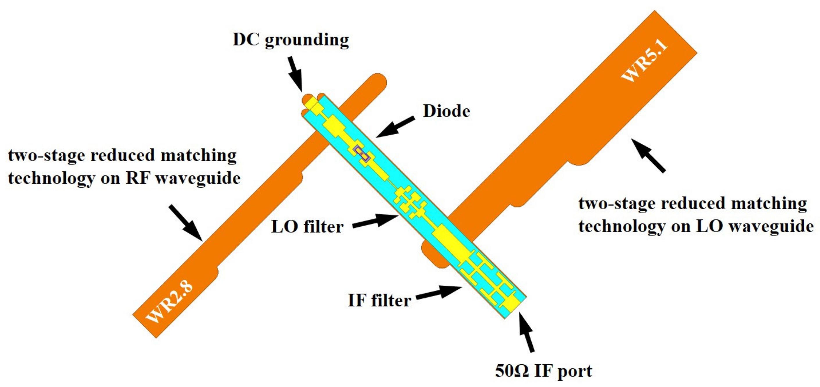
2. Mixer Design
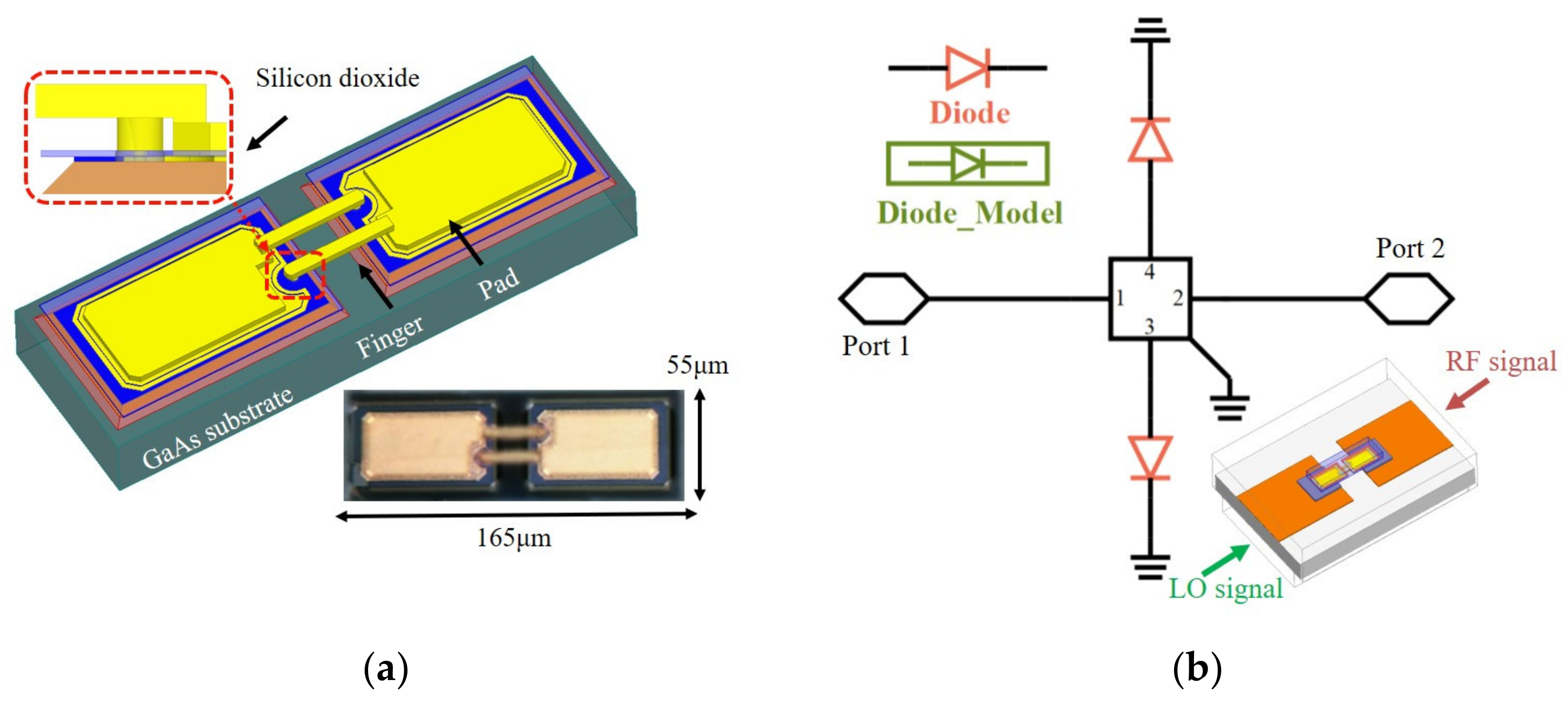
2.1. Schottky Diode
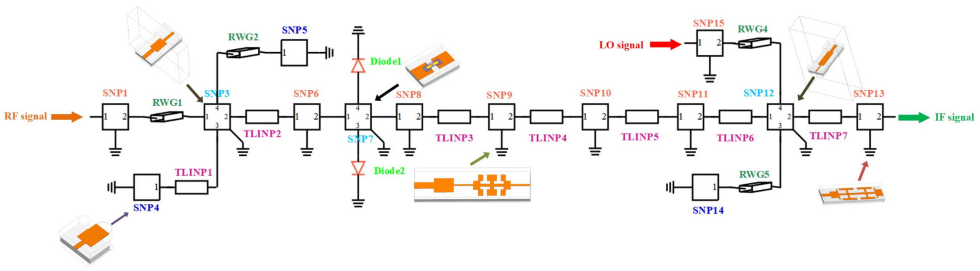
2.2. Improved Active Circuit Model
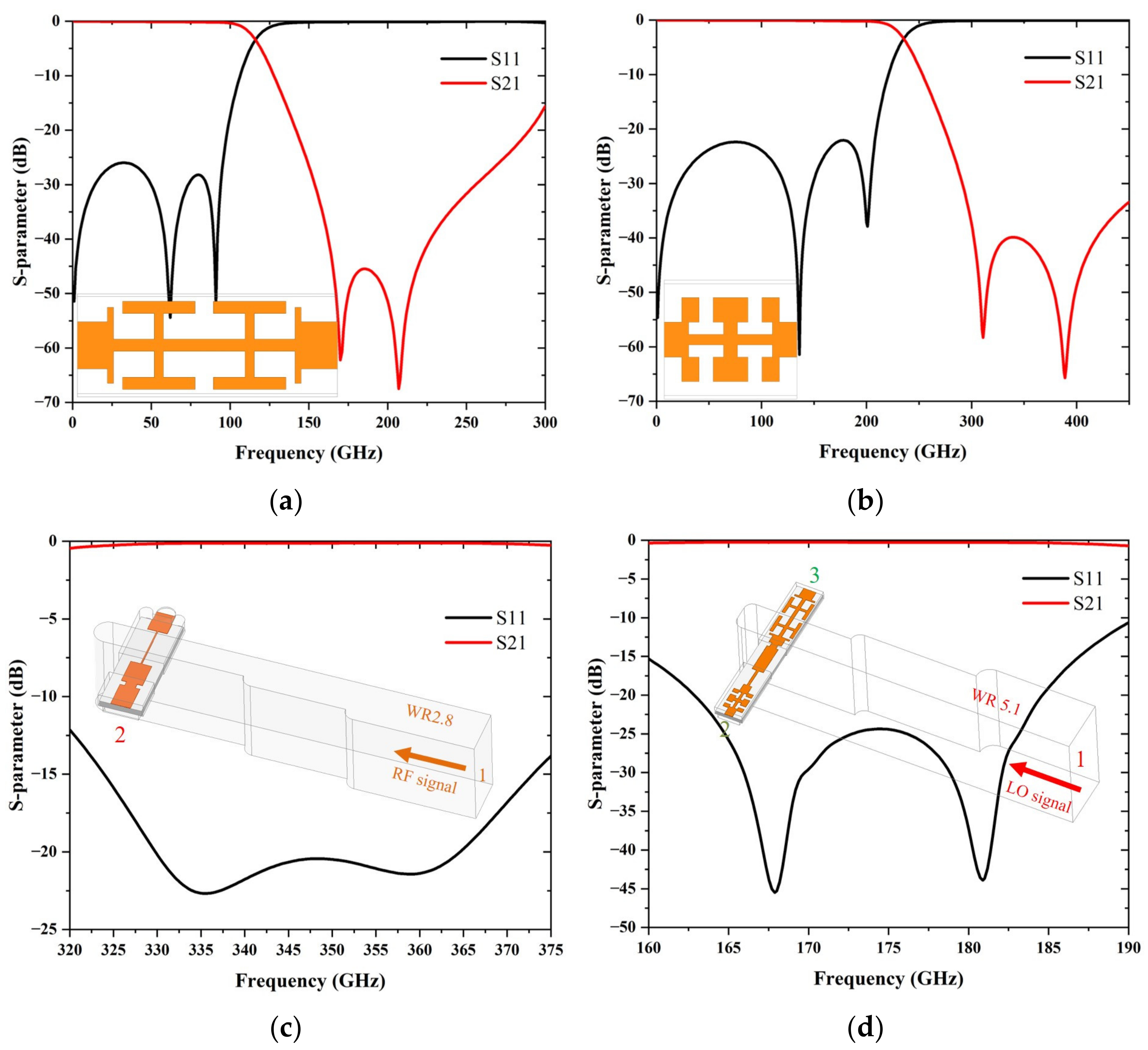
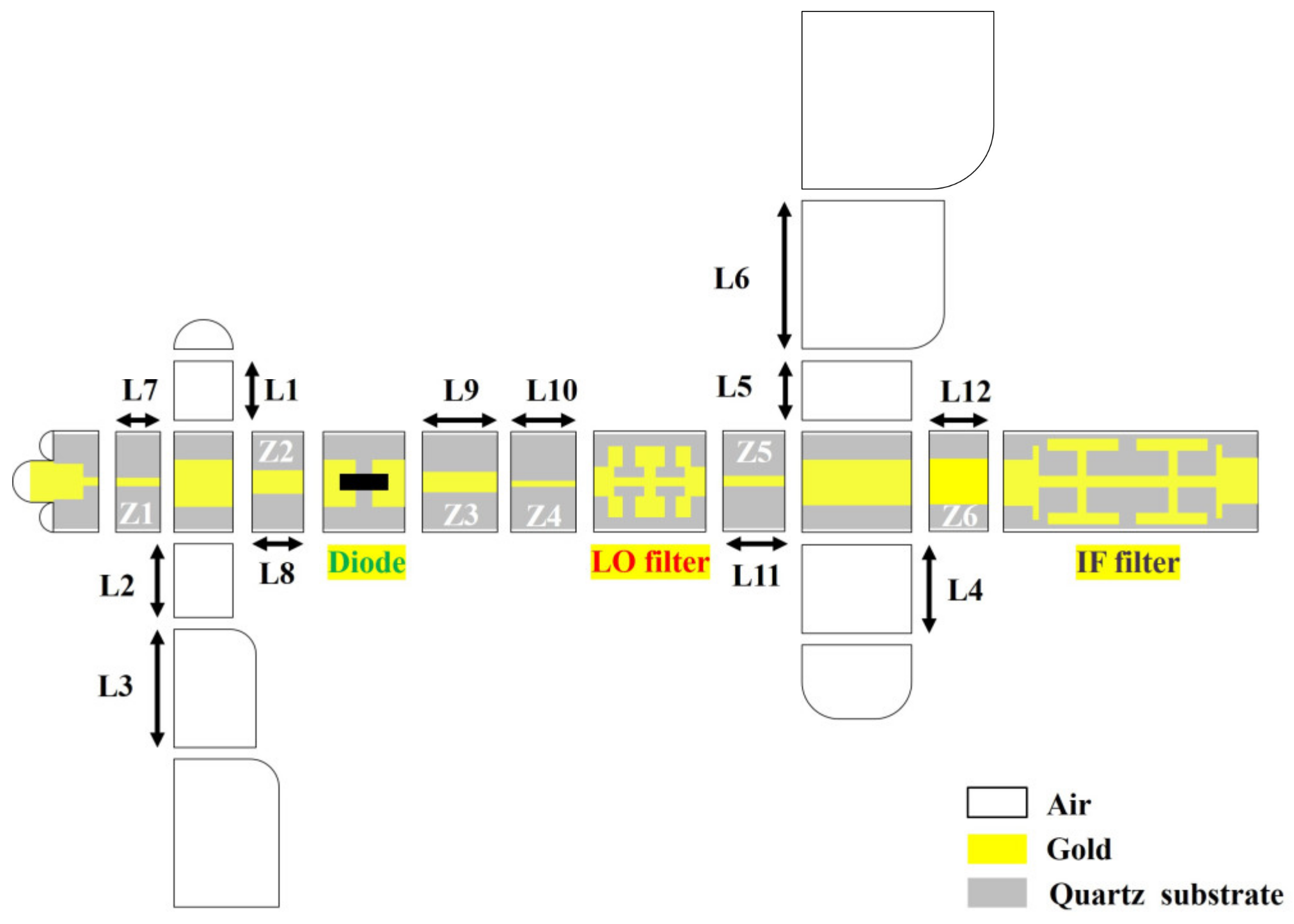
2.3. Filters, RF Transition Model and LO-IF Diplexer Model
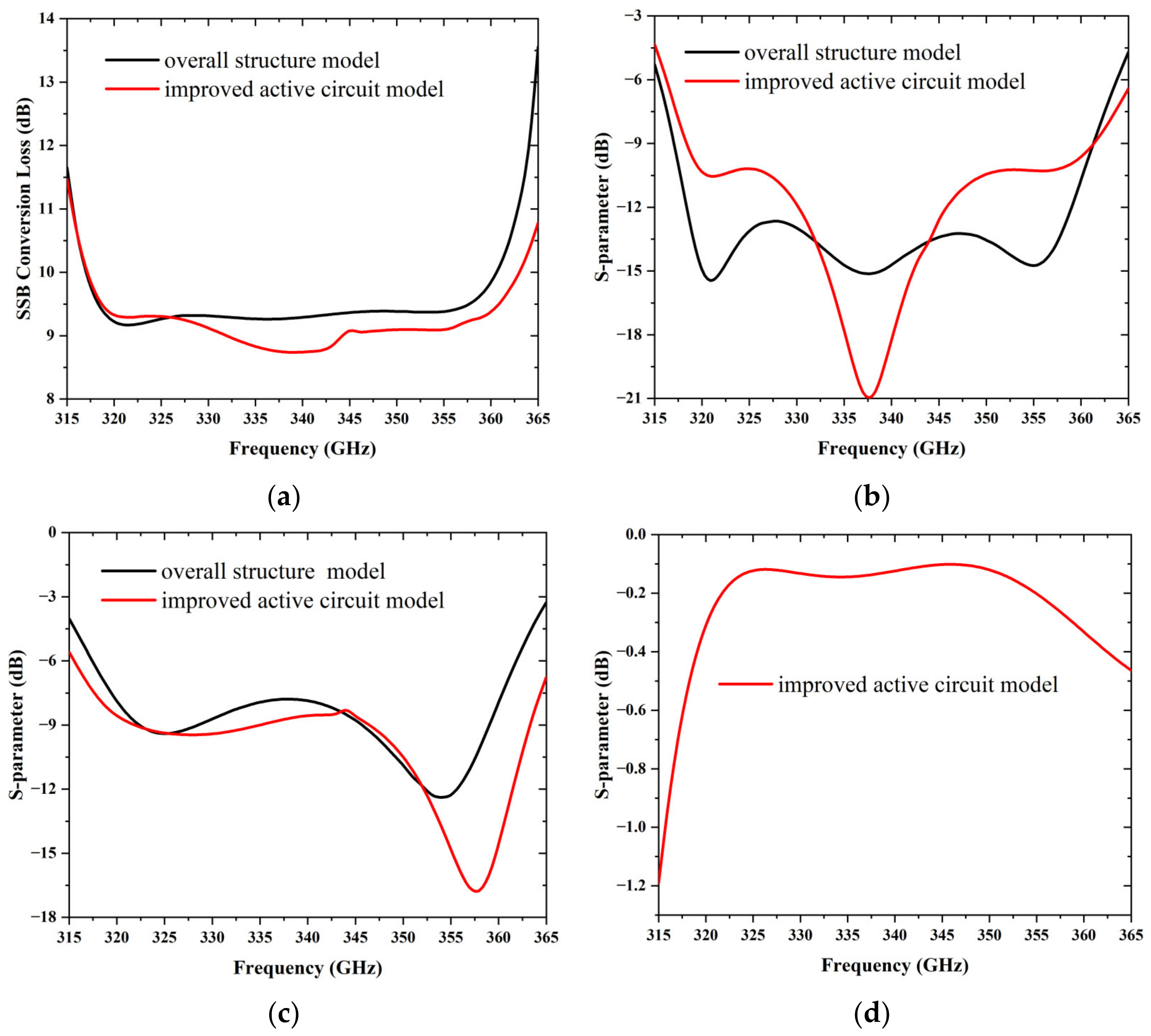
2.4. Simulation
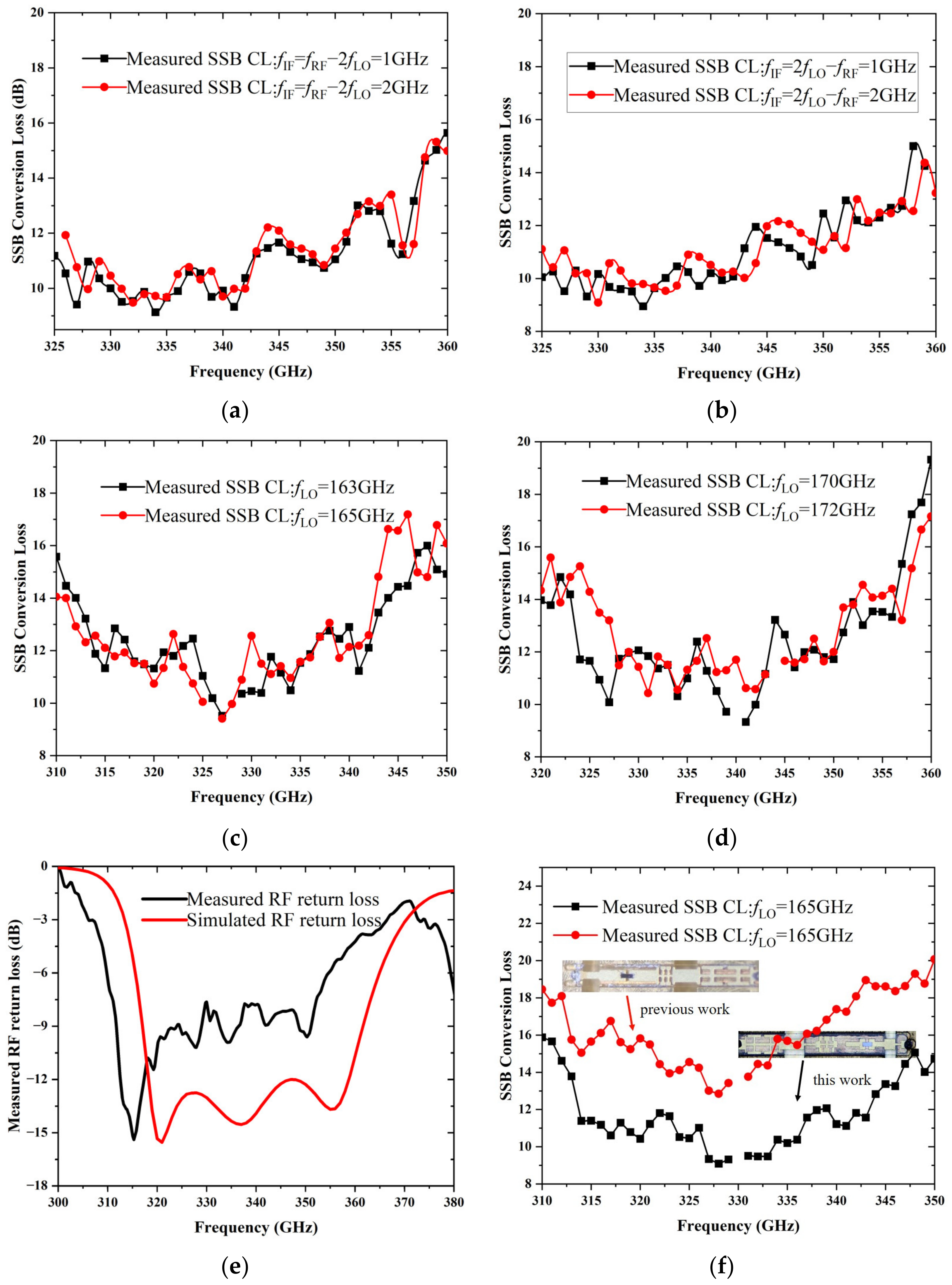
3. Results and Analysis
4. Conclusions
Author Contributions
Funding
Institutional Review Board Statement
Informed Consent Statement
Data Availability Statement
Conflicts of Interest
References
- Harter, T.; Füllner, C.; Kemal, J.N.; Ummethala, S.; Steinmann, J.L.; Brosi, M.; Hesler, J.L.; Bründermann, E.; Müller, A.S.; Freude, W.; et al. Generalized Kramers–Kronig receiver for coherent terahertz communications. Nat. Photonics 2020, 14, 601–606. [Google Scholar] [CrossRef]
- Hillger, P.; Grzyb, J.; Jain, R.; Pfeiffer, U.R. Terahertz Imaging and Sensing Applications With Silicon-Based Technologies. IEEE Trans. Terahertz Sci. Technol. 2019, 9, 1–19. [Google Scholar] [CrossRef]
- Melikyan, A.; Kim, K.; Fontaine, N.; Chandrasekhar, S.; Chen, Y.K.; Dong, P. Inter-polarization mixers for coherent detection of optical signals. Opt. Express 2018, 26, 18523–18531. [Google Scholar] [CrossRef] [PubMed]
- Yang, Y.; Zhang, B.; Ji, D.; Zhao, X.; Fan, Y.; Chen, X. Development of a Wideband 220-GHz Subharmonic Mixer Based on GaAs Monolithic Integration Technology. IEEE Access 2020, 8, 31214–31226. [Google Scholar] [CrossRef]
- Yang, F.; Meng, H.F.; Duo, W.B.; Sun, Z.L. Terahertz Sub-harmonic Mixer Using Discrete Schottky Diode for Planetary Science and Remote Sensing. J. Infrared Millim. Terahertz Waves 2017, 38, 630–637. [Google Scholar] [CrossRef]
- Schlecht, E.; Siles, J.V.; Lee, C.; Lin, R.; Thomas, B.; Chattopadhyay, G.; Mehdi, I. Schottky Diode Based 1.2 THz Receivers Operating at Room-Temperature and Below for Planetary Atmospheric Sounding. IEEE Trans. Terahertz Sci. Technol. 2014, 4, 661–669. [Google Scholar] [CrossRef]
- Chen, C.P.; Jung-Kubiak, C.; Lin, R.H.; Hayton, D.J.; Maestrini, A.E.; Siles, J.; Lee, C.; Peralta, A.; Mehdi, I. Silicon Micromachined Waveguide Circuit for a 2 THz Schottky Receiver: Progress and Challenges. IEEE J. Microw. 2022, 2, 592–598. [Google Scholar] [CrossRef]
- Jayasankar, D.; Drakinskiy, V.; Sobis, P.; Stake, J. Development of Supra-THz Schottky Diode Harmonic Mixers. In Proceedings of the 2021 46th International Conference on Infrared, Millimeter and Terahertz Waves (IRMMW-THz), Chengdu, China, 29 August–3 September 2021; pp. 1–2. [Google Scholar]
- Mehdi, I.; Siles, J.V.; Lee, C.; Schlecht, E. THz Diode Technology: Status, Prospects, and Applications. Proc. IEEE 2017, 105, 990–1007. [Google Scholar] [CrossRef]
- Gaojian, L.; Jun, L.; Hui, X.; Xiaoyang, Z.; Shuantao, L.; Hongxi, Y. Design of a 220GHz Subharmonic Mixer Based on Plannar Schottky Diode. In Proceedings of the 2017 IEEE Asia Pacific Microwave Conference (APMC), Kuala Lumpur, Malaysia, 13–16 November 2017; pp. 418–421. [Google Scholar]
- Zhang, Y.; Zhao, W.; Wang, Y.; Ren, T.; Chen, Y. A 220 GHzsubharmonic mixer based on schottky diodes with an accurate terahertz diode model. Microw. Opt. Technol. Lett. 2016, 58, 2311–2316. [Google Scholar] [CrossRef]
- Zhu, H.; Zhang, Y.; Zheng, Q.; Feng, Z.; Xu, R.; Yan, B. Research on 330GHz Subharmonic Mixer Based on Global Design Method. In Proceedings of the 2019 IEEE Asia-Pacific Microwave Conference (APMC), Singapore, 10–13 December 2019; pp. 168–170. [Google Scholar]
- Cui, J.; Zhang, Y.; Liu, X.; Li, Y.; Wu, C. Design of 199 to 238 GHz broadband subharmonic mixer combining two-stage reduced matching technology with Global Design Method. Int. J. Numer. Model. Electron. Netw. Devices Fields 2019, 33, e2581. [Google Scholar] [CrossRef]
- Yi-Lin, Y.; Bo, Z.; Dong-Feng, J.I.; Yi-Wei, W.; Xiang-Yang, Z.; Yong, F.A.N. A wideband terahertz planar Schottky diode fourth-harmonic mixer with low LO power requirement. J. Infrared Millim. Waves 2020, 39, 540–546. [Google Scholar]
- Tang, A.Y.; Stake, J. Impact of Eddy Currents and Crowding Effects on High-Frequency Losses in Planar Schottky Diodes. IEEE Trans. Electron Devices 2011, 58, 3260–3269. [Google Scholar] [CrossRef] [Green Version]
- Ji, G.; Zhang, D.; Meng, J.; Liu, S.; Yao, C. Design and Measurement of a 0.67 THz Biased Sub-Harmonic Mixer. Electronics 2020, 9, 161. [Google Scholar] [CrossRef] [Green Version]
- Thomas, B.; Rea, S.; Moyna, B.; Alderman, B.; Matheson, D. A 320–360 GHz Subharmonically Pumped Image Rejection Mixer Using Planar Schottky Diodes. IEEE Microw. Wirel. Compon. Lett. 2009, 19, 101–103. [Google Scholar] [CrossRef]
- Liu, Y.; Zhang, B.; Feng, Y.; Lv, X.; Ji, D.; Niu, Z.; Yang, Y.; Zhao, X.; Fan, Y. Development of 340-GHz Transceiver Front End Based on GaAs Monolithic Integration Technology for THz Active Imaging Array. Appl. Sci. 2020, 10, 7924. [Google Scholar] [CrossRef]
- Guo, C.; Shang, X.; Lancaster, M.J.; Xu, J.; Powell, J.; Wang, H.; Parow-Souchon, K.; Henry, M.; Viegas, C.; Alderman, B.; et al. A 290–310 GHz Single Sideband Mixer With Integrated Waveguide Filters. IEEE Trans. Terahertz Sci. Technol. 2018, 8, 446–454. [Google Scholar] [CrossRef]


| Ref. | Freq (GHz) | Conversion Loss (dB) | LO Power (mW) | RF Return Loss (dB) | Reduced Matching Technology | Method |
|---|---|---|---|---|---|---|
| [13] | 200–240 | 7–12 (SSB) 7.84 (min) | 3 | N.A. | Two-stage | GDM |
| [17] | 320–360 | 7.2–24.1 (SSB) 15 (average) | 7–11 | N.A. | Single-stage | N.A. |
| [18] | 320–360 | 7–10 (DSB) 6.9 (min) | 6 | N.A. | Single-stage | GDM |
| [19] | 290–310 | 9–10 (SSB) 6–8 (DSB) | 2.5–3 | >10 | Single-stage | SDM |
| This work | 320–360 | 9–12 (SSB) 8.95 (min) | 5.5 | >12 | Two-stage | An improved active circuit model |
Publisher’s Note: MDPI stays neutral with regard to jurisdictional claims in published maps and institutional affiliations. |
© 2022 by the authors. Licensee MDPI, Basel, Switzerland. This article is an open access article distributed under the terms and conditions of the Creative Commons Attribution (CC BY) license (https://creativecommons.org/licenses/by/4.0/).
Share and Cite
Feng, W.; Yang, P.; Sun, X.; Liang, S.; Zhang, Y. Development of 0.34 THz Sub-Harmonic Mixer Combining Two-Stage Reduced Matching Technology with an Improved Active Circuit Model. Appl. Sci. 2022, 12, 12855. https://doi.org/10.3390/app122412855
Feng W, Yang P, Sun X, Liang S, Zhang Y. Development of 0.34 THz Sub-Harmonic Mixer Combining Two-Stage Reduced Matching Technology with an Improved Active Circuit Model. Applied Sciences. 2022; 12(24):12855. https://doi.org/10.3390/app122412855
Chicago/Turabian StyleFeng, Wei, Penglin Yang, Xuechun Sun, Shixiong Liang, and Yaxin Zhang. 2022. "Development of 0.34 THz Sub-Harmonic Mixer Combining Two-Stage Reduced Matching Technology with an Improved Active Circuit Model" Applied Sciences 12, no. 24: 12855. https://doi.org/10.3390/app122412855
APA StyleFeng, W., Yang, P., Sun, X., Liang, S., & Zhang, Y. (2022). Development of 0.34 THz Sub-Harmonic Mixer Combining Two-Stage Reduced Matching Technology with an Improved Active Circuit Model. Applied Sciences, 12(24), 12855. https://doi.org/10.3390/app122412855