
UAV Platforms and the SfM-MVS Approach in the 3D Surveys and Modelling: A Review in the Cultural Heritage Field

Abstract
:1. Introduction
1.1. Applications of UAV Photogrammetry in CH Field
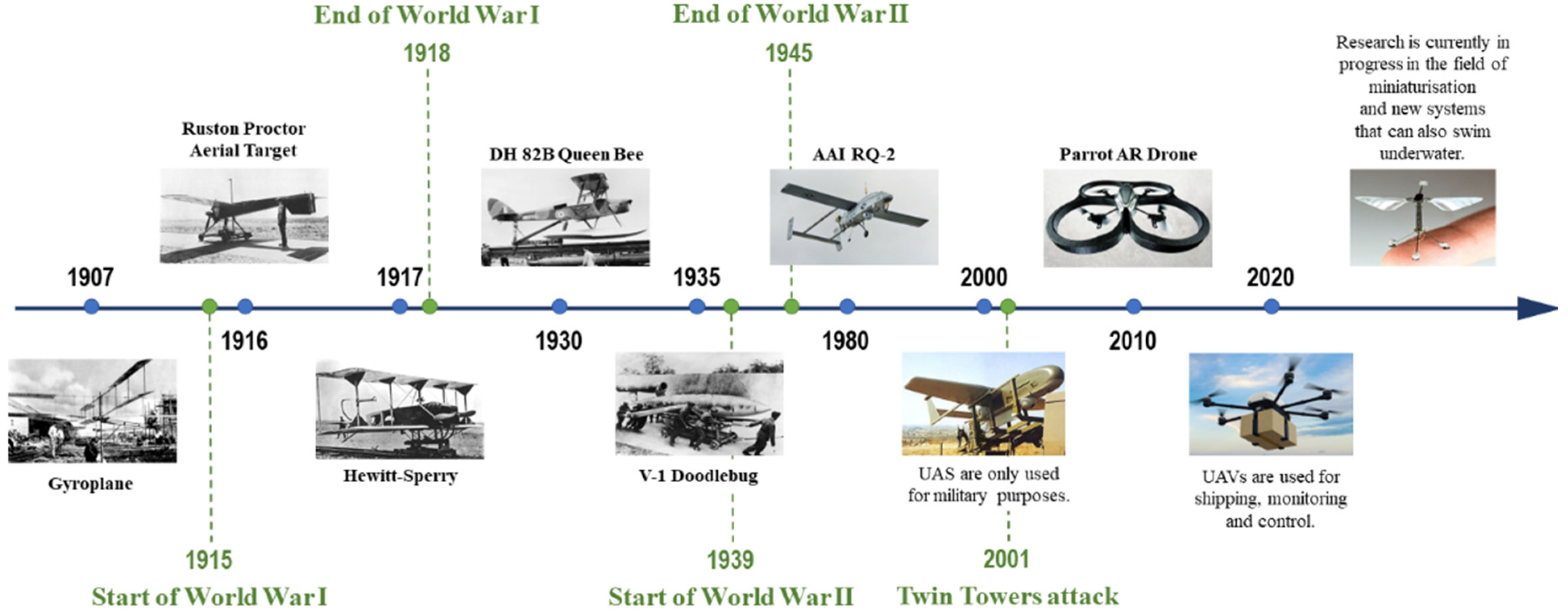
1.2. Brief History of UAV Platform
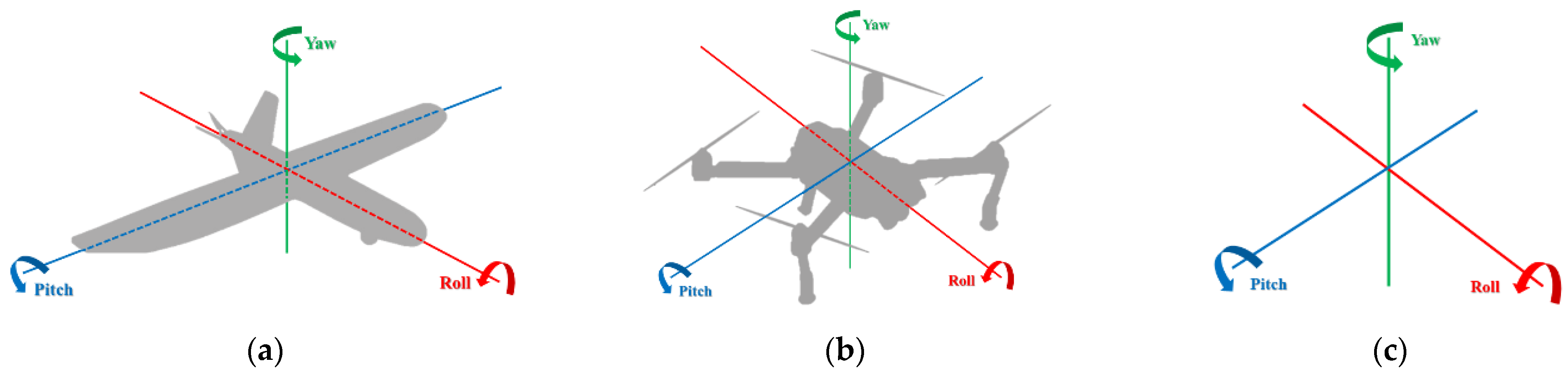
1.3. Structure and Configuration of UAS
1.4. Organization of the Paper
2. Navigation System
2.1. GNSS
2.2. IMU
2.3. Integrated Navigation Systems
2.4. Further Fundamental Components (Compass and Barometers)
3. Aerial Survey by UAS
3.1. Review of Commercial UAS
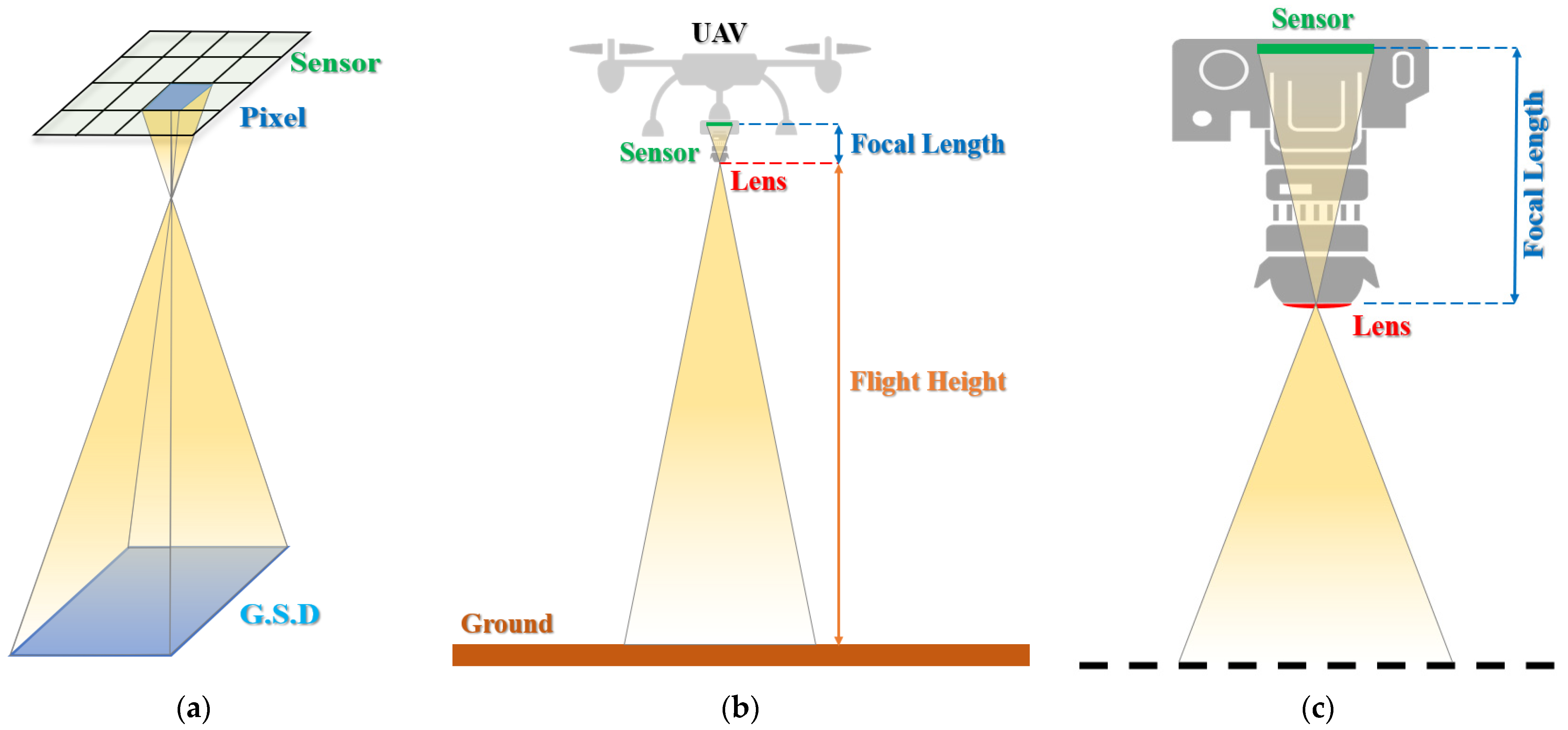
3.2. Mission Planning
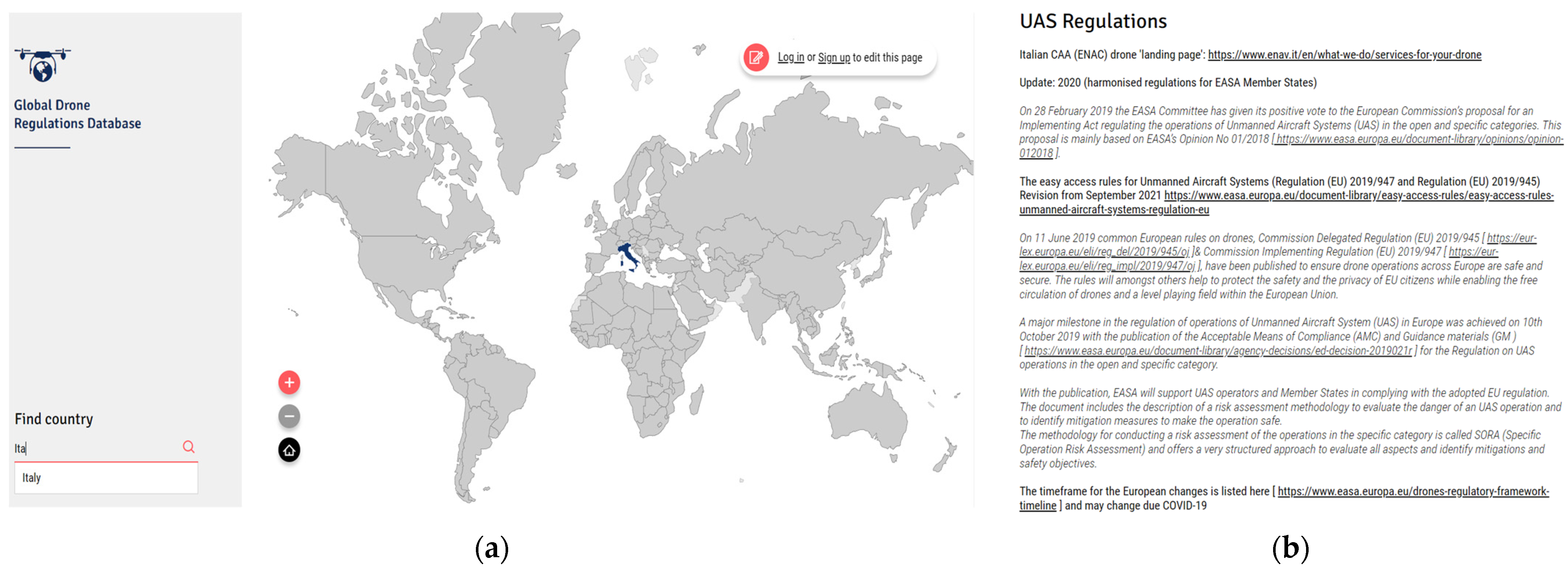
3.3. UAV Regulation
4. Three-Dimensional Modelling by the SfM-MVS Approach
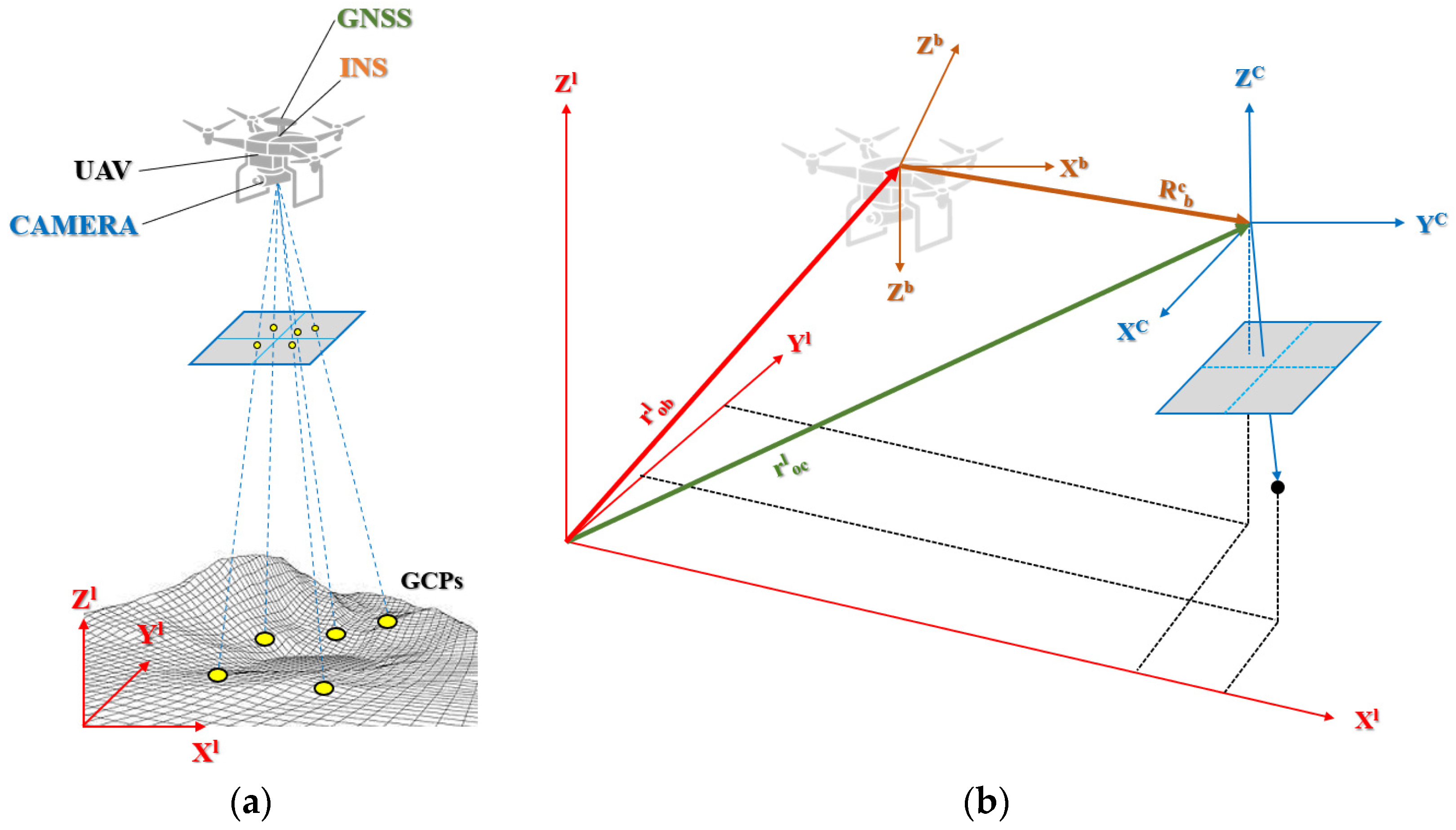
4.1. Direct and Indirect Georeferencing
4.2. Images Acquisition in SfM and MVS Approach
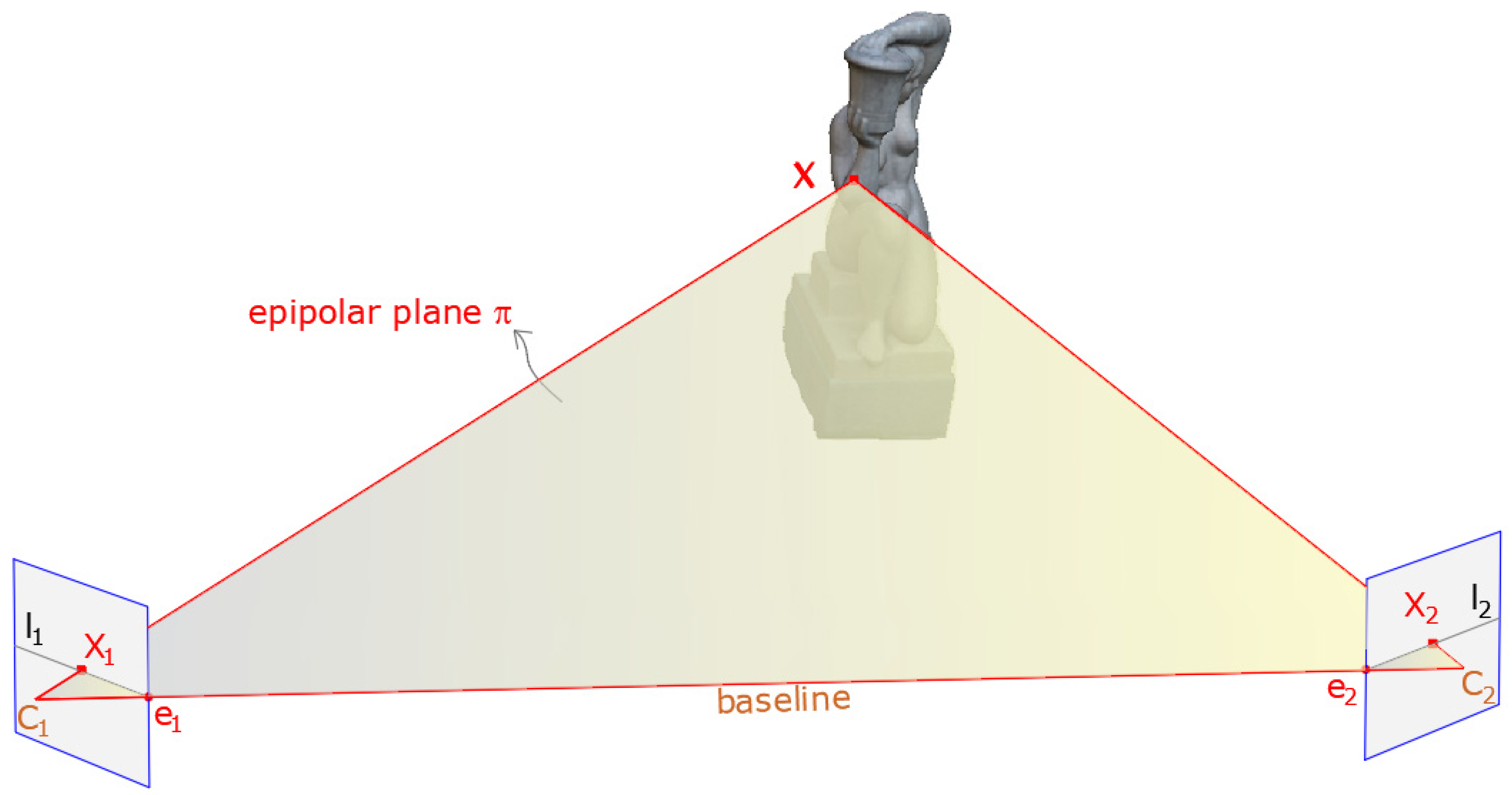
4.3. Multiple View Geometry
4.4. SfM and MVS Pipeline
- -
- Feature matching: determination of images that show common parts of the scene through the analysis of key points obtained in the feature extraction phase.
- -
- Geometric verification: using a robust estimation technique such as RANSAC or RANdom sample consensus, the image pairs that are potentially overlapping are verified [84].
- -
- Regarding reconstruction initialization, the main steps are [85]:
- -
- Initialization: once a geometrically verified image pair has been selected, the points in common between the two images are used as input for the construction of the point cloud.
- -
- Image registration: provided there is a three-dimensional set of points and the corresponding two-dimensional projections in the image, it is necessary to estimate the pose of a calibrated camera (Perspective-n-Point (PnP)) in order to register new images to the current model [84].
- -
- Triangulation: this task determines the 3D locations of the matched points using triangulate, which is based on the direct linear transformation (DLT) algorithm [81];
- -
4.5. Software for UAV Photogrammetry
4.6. Three-Dimensional Accuracy Assessment Based on GCPs in SfM Photogrammetry
5. Experience in Building 3D Point Cloud and Orthophoto
5.1. Three-Dimensional Reconstruction Using UAV Photogrammetry
5.2. Beyond 3D Modelling
6. Conclusions
Author Contributions
Funding
Institutional Review Board Statement
Informed Consent Statement
Data Availability Statement
Acknowledgments
Conflicts of Interest
Abbreviations
| CH | Cultural Heritage |
| BIM | Building Information Modelling |
| HBIM | Heritage Building Information Modelling |
| FEA | Finite Element Analysis |
| FEM | Finite Element Model |
| LiDAR | Light Detection and Ranging |
| SfM | Structure of Motion |
| MVS | Multi-View Stereo |
| SIFT | Scale-Invariant Feature Transform |
| UAV | Unmanned Aerial Vehicle |
| UAS | Unmanned Aircraft System |
| HTOL | Horizontal TakeOff and Landing |
| VTOL | Vertical TakeOff and Landing |
| HALE | High Altitude Long Endurance |
| MALE | Medium Altitude Long Endurance |
| GCP | Ground Control Point |
| CP | Check Point |
| GCS | Ground Control Station |
| GSD | Ground Sample Distance |
| ASL | Above Sea Level |
| AGL | Above Ground Level |
| MB | Motion Blur |
| GNSS | Global Navigation Satellite Systems |
| GPS | Global Positioning System |
| SPP | Single Point Positioning |
| PPP | Precise Point Positioning |
| RTK | Real-Time Kinematic |
| PPK | Post-Processed Kinematic |
| RINEX | Receiver Independent Exchange Format |
| CORS | Continuously Operating Reference Station Services |
| KF | Filter Kalman |
| IMU | Inertial Measurement Unit |
| INS | Inertial Navigation System |
| TC | Tightly Coupled |
| LC | Loosely Coupled |
| EDM | Electronic distance measurement |
| TS | Total Station |
| TOF | Time-of-Flight |
| RMS | Root Mean Square |
| RMSE | Root Mean Square Error |
| IO | Internal Orientation |
| EO | Exterior Orientation |
| DG | Direct Georeferencing |
| RANSAC | RANdom Sample Consensus |
| PnP | Perspective-n-Point |
| DLT | Direct Linear Transformation |
| LM | Levenberg–Marquardt |
References
- Colomina, I.; Molina, P. Unmanned aerial systems for photogrammetry and remote sensing: A review. ISPRS J. Photogramm. Remote Sens. 2014, 92, 79–97. [Google Scholar] [CrossRef] [Green Version]
- Tsouros, D.C.; Bibi, S.; Sarigiannidis, P.G. A review on UAV-based applications for precision agriculture. Information 2019, 10, 349. [Google Scholar] [CrossRef] [Green Version]
- Seo, J.; Duque, L.; Wacker, J.P. Field application of UAS-based bridge inspection. Transp. Res. Rec. 2018, 2672, 72–81. [Google Scholar] [CrossRef]
- Esposito, S.; Fallavollita, P.; Melis, M.G.; Balsi, M.; Jankowski, S. UAS imaging for archaeological survey and documentation. In Proceedings of the Photonics Applications in Astronomy, Communications, Industry, and High-Energy Physics Experiments 2013, Wilga, Poland, 27 May–2 June 2013; Volume 8903, pp. 147–153. [Google Scholar]
- Scianna, A.; La Guardia, M. Survey and photogrammetric restitution of monumental complexes: Issues and solutions—The case of the manfredonic castle of mussomeli. Heritage 2019, 2, 774–786. [Google Scholar] [CrossRef] [Green Version]
- Girelli, V.A.; Borgatti, L.; Dellapasqua, M.; Mandanici, E.; Spreafico, M.C.; Tini, M.A.; Bitelli, G. Integration of geomatics techniques for digitizing highly relevant geological and cultural heritage sites: The case of san leo (italy). In Proceedings of the 26th International CIPA Symposium 2017, Ottawa, ON, Canada, 28 August–1 September 2017; Volume 42. [Google Scholar]
- Campana, S. Drones in archaeology. State-of-the-art and future perspectives. Archaeol. Prospect. 2017, 24, 275–296. [Google Scholar] [CrossRef]
- Opitz, R.S.; Cowley, D.C. Interpreting Archaeological Topography: 3D Data, Visualisation, and Observation; Occasional Publications of the Aerial Archaeology Research Group 5; Oxbow: Oxford, UK, 2013; pp. 115–122. [Google Scholar]
- Saleri, R.; Cappellini, V.; Nony, N.; De Luca, L.; Pierrot-Deseilligny, M.; Bardiere, E.; Campi, M. UAV photogrammetry for archaeological survey: The Theaters area of Pompeii. In Proceedings of the 2013 Digital Heritage International Congress (DigitalHeritage), Marseille, France, 28 October–1 November 2013; Volume 2, pp. 497–502. [Google Scholar]
- Mouget, A.; Lucet, G. Photogrammetric archaeological survey with UAV. In Proceedings of the ISPRS Technical Commission V Symposium, Riva del Garda, Italy, 23–25 June 2014; Volume 2. [Google Scholar]
- Adami, A.; Fregonese, L.; Gallo, M.; Helder, J.; Pepe, M.; Treccani, D. Ultra light UAV systems for the metrical documentation of cultural heritage: Applications for architecture and archaeology. In Proceedings of the 6th International Workshop LowCost 3D–Sensors, Algorithms, Applications, Strasbourg, France, 2–3 December 2019; Volume 42, pp. 15–21. [Google Scholar]
- Kadhim, I.; Abed, F.M. The Potential of LiDAR and UAV-photogrammetric data analysis to interpret archaeological sites: A Case Study of Chun Castle in South-West England. ISPRS Int. J. Geo-Inf. 2021, 10, 41. [Google Scholar] [CrossRef]
- Dasari, S.; Mesapam, S.; Kumarapu, K.; Mandla, V.R. UAV in Development of 3D Heritage Monument Model: A Case Study of Kota Gullu, Warangal, India. J. Indian Soc. Remote Sens. 2021, 49, 1733–1737. [Google Scholar] [CrossRef]
- Kanun, E.; Alptekin, A.; Karataş, L.; Yakar, M. The use of UAV photogrammetry in modeling ancient structures: A case study of “Kanytellis”. Adv. UAV 2022, 2, 41–50. [Google Scholar]
- Pepe, M.; Costantino, D. UAV photogrammetry and 3D modelling of complex architecture for maintenance purposes: The case study of the masonry bridge on the Sele river, Italy. Period. Polytech. Civ. Eng. 2021, 65, 191–203. [Google Scholar] [CrossRef]
- Baiocchi, V.; Onori, M.; Scuti, M. Integrated Geomatic Techniques for the Localization and Georeferencing of Ancient Hermitages. Int. Arch. Photogramm. Remote Sens. Spat. Inf. Sci. 2021, 46, 31–37. [Google Scholar] [CrossRef]
- Ozimek, A.; Ozimek, P.; Skabek, K.; Labędź, P. Digital modelling and accuracy verification of a complex architectural object based on photogrammetric reconstruction. Buildings 2021, 11, 206. [Google Scholar] [CrossRef]
- Martínez-Carricondo, P.; Carvajal-Ramírez, F.; Yero-Paneque, L.; Agüera-Vega, F. Combination of HBIM and UAV photogrammetry for modelling and documentation of forgotten heritage. Case study: Isabel II dam in Níjar (Almería, Spain). Herit. Sci. 2021, 9, 95. [Google Scholar] [CrossRef]
- Sabil, A.; Mahmud, N.A.A.; Utaberta, N.; Amin, N.D.N.; Asif, N.; Yusof, H. The Application of Photogrammetry in Architecture Historical Documentation: The measured drawing of Tanjung Sembrong Mosque and Teratak Selari Bonda. IOP Conf. Ser. Earth Environ. Sci. 2022, 1022, 012007. [Google Scholar] [CrossRef]
- Prisacariu, V. The history and the evolution of UAVs from the beginning till the 70s. J. Def. Resour. Manag. JoDRM 2017, 8, 181–189. [Google Scholar]
- Udeanu, G.; Dobrescu, A.; Oltean, M. Unmanned aerial vehicle in military operations. Sci Res Educ Air Force 2016, 18, 199–206. [Google Scholar] [CrossRef]
- Vogler, L.C.A.; Hughes, T. Anything but ‘drone’: Why Naming Matters.
- Birtchnell, T.; Gibson, C. Less talk more drone: Social research with UAVs. J. Geogr. High. Educ. 2015, 39, 182–189. [Google Scholar] [CrossRef] [Green Version]
- Major, R. RQ-2 Pioneer: The Flawed System that Redefined US Unmanned Aviation; Air Command And Staff College Mawell AFB United States: Montgomery, AL, USA, 2012. [Google Scholar]
- Saboor, A.; Coene, S.; Vinogradov, E.; Tanghe, E.; Joseph, W.; Pollin, S. Elevating the future of mobility: UAV-enabled Intelligent Transportation Systems. arXiv 2021, arXiv:2110.09934. [Google Scholar]
- Mohsan, S.A.H.; Othman, N.Q.H.; Khan, M.A.; Amjad, H.; Żywiołek, J. A Comprehensive Review of Micro UAV Charging Techniques. Micromachines 2022, 13, 977. [Google Scholar] [CrossRef]
- Barnhart, R.K.; Marshall, D.M.; Shappee, E. Introduction to Unmanned Aircraft Systems; CRC Press: Boca Raton, FL, USA, 2021. [Google Scholar]
- Austin, R. Unmanned Aircraft Systems: UAVS Design, Development and Deployment; John Wiley & Sons: Hoboken, NJ, USA, 2011. [Google Scholar]
- PS, R.; Jeyan, M.L. Mini Unmanned Aerial Systems (UAV)-A Review of the Parameters for Classification of a Mini UAV. Int. J. Aviat. Aeronaut. Aerosp. 2020, 7, 5. [Google Scholar] [CrossRef]
- Eisenbeiß, H. UAV Photogrammetry. Ph.D. Thesis, University of Technology Dresden, Dresden, Germany, 2009. [Google Scholar]
- Eisenbeiss, H.; Sauerbier, M. Investigation of UAV systems and flight modes for photogrammetric applications. Photogramm. Rec. 2011, 26, 400–421. [Google Scholar] [CrossRef]
- Quan, Q. Introduction to Multicopter Design and Control; Springer: Berlin/Heidelberg, Germany, 2017. [Google Scholar]
- Verbeke, J.; Hulens, D.; Ramon, H.; Goedeme, T.; De Schutter, J. The design and construction of a high endurance hexacopter suited for narrow corridors. In Proceedings of the 2014 International Conference on Unmanned Aircraft Systems (ICUAS), Orlando, FL, USA, 27–30 May 2014; pp. 543–551. [Google Scholar]
- Singhal, G.; Bansod, B.; Mathew, L. Unmanned aerial vehicle classification, applications and challenges: A review. Preprints 2018. [Google Scholar] [CrossRef] [Green Version]
- Zhao, S.; Cui, X.; Lu, M. Single point positioning using full and fractional pseudorange measurements from GPS and BDS. Surv. Rev. 2021, 53, 27–34. [Google Scholar] [CrossRef]
- Kaplan, E.D.; Hegarty, C. Understanding GPS/GNSS: Principles and Applications; Artech House: Norwood, MA, USA, 2017. [Google Scholar]
- Pepe, M. CORS architecture and evaluation of positioning by low-cost GNSS receiver. Geod. Cartogr. 2018, 44, 36–44. [Google Scholar] [CrossRef]
- Schwieger, V.; Lilje, M.; Sarib, R. GNSS CORS-Reference frames and services. In Proceedings of the 7th FIG Regional Conference, Hanoi, Vietnam, 19–22 October 2009; Volume 19, p. 2009. [Google Scholar]
- Tomaštík, J.; Mokroš, M.; Surovỳ, P.; Grznárová, A.; Merganič, J. UAV RTK/PPK method—An optimal solution for mapping inaccessible forested areas? Remote Sens. 2019, 11, 721. [Google Scholar] [CrossRef] [Green Version]
- Zhang, H.; Aldana-Jague, E.; Clapuyt, F.; Wilken, F.; Vanacker, V.; Van Oost, K. Evaluating the potential of post-processing kinematic (PPK) georeferencing for UAV-based structure-from-motion (SfM) photogrammetry and surface change detection. Earth Surf. Dyn. 2019, 7, 807–827. [Google Scholar] [CrossRef] [Green Version]
- Pepe, M.; Costantino, D.; Vozza, G.; Alfio, V.S. Comparison of two approaches to gnss positioning using code pseudoranges generated by smartphone device. Appl. Sci. 2021, 11, 4787. [Google Scholar] [CrossRef]
- Jason. Available online: https://jason.docs.rokubun.cat/strategies/ (accessed on 5 September 2022).
- Krajník, T.; Vonásek, V.; Fišer, D.; Faigl, J. AR-drone as a platform for robotic research and education. In Proceedings of the International Conference on Research and Education in Robotics, Prague, Czech Republic, 15-17 June 2011; Springer: Berlin/Heidelberg, Germany, 2011; pp. 172–186. [Google Scholar]
- Woodman, O.J. An Introduction to Inertial Navigation; University of Cambridge, Computer Laboratory: Cambridge, UK, 2007. [Google Scholar]
- de Alteriis, G.; Conte, C.; Moriello, R.S.L.; Accardo, D. Use of consumer-grade MEMS inertial sensors for accurate attitude determination of drones. In Proceedings of the 2020 IEEE 7th International Workshop on Metrology for AeroSpace (MetroAeroSpace), Pisa, Italy, 22–24 June 2020; pp. 534–538. [Google Scholar]
- Turner, D.; Lucieer, A.; Wallace, L. Direct georeferencing of ultrahigh-resolution UAV imagery. IEEE Trans. Geosci. Remote Sens. 2013, 52, 2738–2745. [Google Scholar] [CrossRef]
- Petovello, M.G. Real-Time Integration of a Tactical-Grade IMU and GPS for High-Accuracy Positioning and Navigation. Ph.D. Thesis, The University of Calgary, Calgary, AB, Canada, 2003. [Google Scholar]
- Cazzaniga, N.E. Sviluppo e implementazione di algoritmi per la navigazione inerziale assistita. PhD Thesis, Tesi di dottorato, DIIAR-Sezione Rilevamento, Politecnico di Milano, Milano, 2007. [Google Scholar]
- Chiang, K.-W.; Tsai, M.-L.; Naser, E.-S.; Habib, A.; Chu, C.-H. A new calibration method using low cost MEM IMUs to verify the performance of UAV-borne MMS payloads. Sensors 2015, 15, 6560–6585. [Google Scholar] [CrossRef] [Green Version]
- Wendel, J.; Trommer, G.F. Tightly coupled GPS/INS integration for missile applications. Aerosp. Sci. Technol. 2004, 8, 627–634. [Google Scholar] [CrossRef]
- Mian, O.; Lutes, J.; Lipa, G.; Hutton, J.J.; Gavelle, E.; Borghini, S. Direct georeferencing on small unmanned aerial platforms for improved reliability and accuracy of mapping without the need for ground control points. Int. Arch. Photogramm. Remote Sens. Spat. Inf. Sci. 2015, 40, 397. [Google Scholar] [CrossRef] [Green Version]
- Chung, P.-H.; Ma, D.-M.; Shiau, J.-K. Design, manufacturing, and flight testing of an experimental flying wing UAV. Appl. Sci. 2019, 9, 3043. [Google Scholar] [CrossRef] [Green Version]
- Gandor, F.; Rehak, M.; Skaloud, J. Photogrammetric mission planner for RPAS. Int. Arch. Photogramm. Remote Sens. Spat. Inf. Sci. 2015, 40, 61. [Google Scholar] [CrossRef] [Green Version]
- Pepe, M.; Fregonese, L.; Scaioni, M. Planning airborne photogrammetry and remote-sensing missions with modern platforms and sensors. Eur. J. Remote Sens. 2018, 51, 412–436. [Google Scholar] [CrossRef]
- Moustris, G.; Tzafestas, C. Image-Guided Motion Compensation for Robotic-Assisted Beating Heart Surgery. In Handbook of Robotic and Image-Guided Surgery; Elsevier: Amsterdam, The Netherlands, 2020; pp. 363–374. [Google Scholar]
- Neumann, K.J. Digital Aerial Cameras; Intergraph Z/I Deutschland GmbH: Aalen, Germany, 2005; pp. 1–5. [Google Scholar]
- Hernandez-Lopez, D.; Felipe-Garcia, B.; Gonzalez-Aguilera, D.; Arias-Perez, B. An automatic approach to UAV flight planning and control for photogrammetric applications. Photogramm. Eng. Remote Sens. 2013, 79, 87–98. [Google Scholar] [CrossRef]
- Pix4D Capture. Available online: https://www.pix4d.com/product/pix4dcapture (accessed on 13 September 2022).
- UgCS UAV Mission Planning. Available online: https://www.geometrics.com/software/ugcs-uav-mission-planning-software/ (accessed on 13 September 2022).
- Uav Flight Map Pro Planner. Available online: www.uavflightmap.com (accessed on 13 September 2022).
- DJI GS PRO. Available online: https://www.dji.com/it/ground-station-pro (accessed on 13 September 2022).
- eMotion. Available online: https://www.sensefly.com/drone-software/emotion/ (accessed on 13 September 2022).
- Şasi, A.; Yakar, M. Photogrammetric modelling of sakahane masjid using an unmanned aerial vehicle. Turk. J. Eng. 2017, 1, 82–87. [Google Scholar] [CrossRef] [Green Version]
- Hong, Y.; Fang, J.; Tao, Y. Ground control station development for autonomous UAV. In Proceedings of the International Conference on Intelligent Robotics and Applications; Springer: Berlin/Heidelberg, Germany, 2008; pp. 36–44. [Google Scholar]
- License To Fly. Available online: https://surfshark.com/drone-privacy-laws (accessed on 2 September 2022).
- Global Drone Regulations Database. Available online: https://www.droneregulations.info/ (accessed on 2 September 2022).
- Kutila, M.; Korpinen, J.; Viitanen, J. Camera calibration in machine automation. In Proceedings of the 2nd International Conference on Machine Automation, ICMA 2000, Osaka, Japan, 27–29 September 2001; pp. 211–216. [Google Scholar]
- Duane, C.B. Close-range camera calibration. Photogramm. Eng. 1971, 37, 855–866. [Google Scholar]
- Verhoeven, G.; Wieser, M.; Briese, C.; Doneus, M. Positioning in time and space: Cost-effective exterior orientation for airborne archaeological photographs. In Proceedings of the XXIV International CIPA Symposium, Strasbourg, France, 2–6 September 2013; Volume 2, pp. 313–318. [Google Scholar]
- Jozkow, G.; Toth, C. Georeferencing experiments with UAS imagery. ISPRS Ann. Photogramm. Remote Sens. Spat. Inf. Sci. 2014, 2, 25. [Google Scholar] [CrossRef] [Green Version]
- Gabrlik, P. The use of direct georeferencing in aerial photogrammetry with micro UAV. IFAC-Pap. 2015, 48, 380–385. [Google Scholar] [CrossRef]
- Bujakiewicz, A.; Podlasiak, P.; Zawieska, D. Georeferencing of close range photogrammetric data. Arch. Fotogram. Kartogr. Teledetekcji 2011, 22, 91–104. [Google Scholar]
- Hutton, J.; Mostafa, M.M. 10 years of direct georeferencing for airborne photogrammetry. GIS Bus. GeoBit 2005, 11, 33–41. [Google Scholar]
- Fraser, C.S. Digital camera self-calibration. ISPRS J. Photogramm. Remote Sens. 1997, 52, 149–159. [Google Scholar] [CrossRef]
- Villanueva, J.K.S.; Blanco, A.C. Optimization of ground control point (GCP) configuration for unmanned aerial vehicle (UAV) survey using structure from motion (SFM). Int. Arch. Photogramm. Remote Sens. Spat. Inf. Sci. 2019, 42, 167–174. [Google Scholar] [CrossRef] [Green Version]
- Martínez-Carricondo, P.; Agüera-Vega, F.; Carvajal-Ramírez, F.; Mesas-Carrascosa, F.-J.; García-Ferrer, A.; Pérez-Porras, F.-J. Assessment of UAV-photogrammetric mapping accuracy based on variation of ground control points. Int. J. Appl. Earth Obs. Geoinf. 2018, 72, 1–10. [Google Scholar] [CrossRef]
- Cramer, M.; Stallmann, D.; Haala, N. Direct georeferencing using GPS/inertial exterior orientations for photogrammetric applications. Int. Arch. Photogramm. Remote Sens. 2000, 33, 198–205. [Google Scholar]
- Fraser, C.S. Network Design in Close-range Photogrammetry and Machine Vision. In Proceedings of the 26th International CIPA Symposium 2017, Ottawa, ON, Canada, 28 August–1 September 2017; pp. 256–282. [Google Scholar]
- Fraser, C. Camera calibration considerations for UAV photogrammetry. In Proceedings of the ISPRS TC II Symposium: Towards Photogrammetry, Riva del Garda, Italy, 3–7 June 2018. [Google Scholar]
- Solem, J.E. Programming Computer Vision with Python: Tools and Algorithms for Analyzing Images; O’Reilly Media, Inc.: Sebastopol, CA, USA, 2012. [Google Scholar]
- Hartley, R.; Zisserman, A. Multiple View Geometry in Computer Vision; Cambridge University Press: Cambridge, UK, 2003. [Google Scholar]
- Jiang, S.; Jiang, C.; Jiang, W. Efficient structure from motion for large-scale UAV images: A review and a comparison of SfM tools. ISPRS J. Photogramm. Remote Sens. 2020, 167, 230–251. [Google Scholar] [CrossRef]
- Lowe, G. Sift-the scale invariant feature transform. Int. J. 2004, 2, 2. [Google Scholar]
- Fischler, M.A.; Bolles, R.C. Perceptual organization and curve partitioning. In Readings in Computer Vision; Elsevier: Amsterdam, The Netherlands, 1987; pp. 210–215. [Google Scholar]
- Bianco, S.; Ciocca, G.; Marelli, D. Evaluating the performance of structure from motion pipelines. J. Imaging 2018, 4, 98. [Google Scholar] [CrossRef] [Green Version]
- Nocedal, J.; Wright, S.J. Numerical Optimization; Springer: Berlin/Heidelberg, Germany, 1999. [Google Scholar]
- Wei, X.; Zhang, Y.; Li, Z.; Fu, Y.; Xue, X. Deepsfm: Structure from motion via deep bundle adjustment. In Proceedings of the European Conference on Computer Vision; Springer: Berlin/Heidelberg, Germany, 2020; pp. 230–247. [Google Scholar]
- Furukawa, Y.; Hernández, C. Multi-view stereo: A tutorial. Found. Trends Comput. Graph. Vis. 2015, 9, 1–148. [Google Scholar] [CrossRef]
- Seitz, S.M.; Curless, B.; Diebel, J.; Scharstein, D.; Szeliski, R. A Comparison and Evaluation of Multi-View Stereo Reconstruction Algorithms. In Proceedings of the 2006 IEEE Computer Society Conference on Computer Vision and Pattern Recognition (CVPR’06), New York, NY, USA, 17–22 June 2006; Volume 1, pp. 519–528. [Google Scholar]
- Fraser, C.S. Automatic Camera Calibration in Close Range Photogrammetry. Photogramm. Eng. Remote Sens. 2013, 79, 381–388. [Google Scholar] [CrossRef] [Green Version]
- Furukawa, Y.; Ponce, J. Accurate, Dense, and Robust Multiview Stereopsis. IEEE Trans. Pattern Anal. Mach. Intell. 2010, 32, 1362–1376. [Google Scholar] [CrossRef]
- Goesele, M.; Snavely, N.; Curless, B.; Hoppe, H.; Seitz, S.M. Multi-View Stereo for Community Photo Collections. In Proceedings of the 2007 IEEE 11th International Conference on Computer Vision, Rio de Janeiro, Brazil, 14–21 October 2007; pp. 1–8. [Google Scholar]
- Shen, S. Accurate multiple view 3d reconstruction using patch-based stereo for large-scale scenes. IEEE Trans. Image Process. 2013, 22, 1901–1914. [Google Scholar] [CrossRef] [PubMed]
- Agisoft Metashape. Available online: https://www.agisoft.com/ (accessed on 5 September 2022).
- Tinkham, W.T.; Swayze, N.C. Influence of Agisoft Metashape parameters on UAS structure from motion individual tree detection from canopy height models. Forests 2021, 12, 250. [Google Scholar] [CrossRef]
- 3DF Zephyr. Available online: https://www.3dflow.net/it (accessed on 5 September 2022).
- Oniga, V.-E.; Breaban, A.-I.; Pfeifer, N.; Chirila, C. Determining the suitable number of ground control points for UAS images georeferencing by varying number and spatial distribution. Remote Sens. 2020, 12, 876. [Google Scholar] [CrossRef] [Green Version]
- Autodesk ReCap. Available online: https://www.autodesk.com/products/recap/overview?term=1-YEAR&tab=subscription (accessed on 5 September 2022).
- Jones, C.A.; Church, E. Photogrammetry is for everyone: Structure-from-motion software user experiences in archaeology. J. Archaeol. Sci. Rep. 2020, 30, 102261. [Google Scholar] [CrossRef]
- Pix4D. Available online: https://www.pix4d.com/ (accessed on 5 September 2022).
- Barbasiewicz, A.; Widerski, T.; Daliga, K. The analysis of the accuracy of spatial models using photogrammetric software: Agisoft Photoscan and Pix4D. E3S Web Conf. 2018, 26, 00012. [Google Scholar] [CrossRef]
- PhotoModeler. Available online: https://www.photomodeler.com/ (accessed on 5 September 2022).
- Irschara, A.; Kaufmann, V.; Klopschitz, M.; Bischof, H.; Leberl, F. Towards fully automatic photogrammetric reconstruction using digital images taken from UAVs. In Proceedings of the ISPRS TC VII Symposium—100 Years ISPRS, Vienna, Austria, 5–7 July 2010. [Google Scholar]
- Reality Capture. Available online: https://www.capturingreality.com/ (accessed on 5 September 2022).
- Kingsland, K. Comparative analysis of digital photogrammetry software for cultural heritage. Digit. Appl. Archaeol. Cult. Herit. 2020, 18, e00157. [Google Scholar] [CrossRef]
- Trimble Inpho. Available online: https://geospatial.trimble.com/products-and-solutions/trimble-inpho (accessed on 5 September 2022).
- Lumban-Gaol, Y.A.; Murtiyoso, A.; Nugroho, B.H. Investigations on the Bundle Adjustment Results from Sfm-Based Software for Mapping Purposes. In Proceedings of the ISPRS TC II Mid-term Symposium “Towards Photogrammetry 2020”, Riva del Garda, Italy, 4–7 June 2018. [Google Scholar]
- WebODM. Available online: https://www.opendronemap.org/webodm/ (accessed on 5 September 2022).
- Vacca, G. WEB Open Drone Map (WebODM) a Software Open Source to Photogrammetry Process. In Proceedings of the Fig Working Week 2020. Smart Surveyors for Land and Water Management, Amsterdam, The Netherlands, 10–14 May 2020. [Google Scholar]
- Bartoš, K.; Pukanská, K.; Sabová, J. Overview of available open-source photogrammetric software, its use and analysis. Int. J. Innov. Educ. Res. 2014, 2, 62–70. [Google Scholar] [CrossRef]
- Stathopoulou, E.K.; Welponer, M.; Remondino, F. Open-source image-based 3D reconstruction pipelines: Review, comparison and evaluation. Int. Arch. Photogramm. Remote Sens. Spat. Inf. Sci. 2019, XLII-2W17, 331–338. [Google Scholar] [CrossRef]
- Regard 3D. Available online: http://www.regard3d.org/ (accessed on 5 September 2022).
- Palestini, C.; Basso, A. Low-Cost Technological Implementations Related to Integrated Application Experiments. Int. Arch. Photogramm. Remote Sens. Spat. Inf. Sci. 2019, XLII-2/W17, 241–248. [Google Scholar] [CrossRef] [Green Version]
- MicMac. Available online: https://micmac.ensg.eu/index.php/Accueil (accessed on 5 September 2022).
- Rupnik, E.; Daakir, M.; Pierrot Deseilligny, M. MicMac–a free, open-source solution for photogrammetry. Open Geospat. Data Softw. Stand. 2017, 2, 14. [Google Scholar] [CrossRef] [Green Version]
- Jaud, M.; Passot, S.; Allemand, P.; Le Dantec, N.; Grandjean, P.; Delacourt, C. Suggestions to limit geometric distortions in the reconstruction of linear coastal landforms by SfM photogrammetry with PhotoScan® and MicMac® for UAV surveys with restricted GCPs pattern. Drones 2018, 3, 2. [Google Scholar] [CrossRef] [Green Version]
- Meshroom. Available online: https://alicevision.org/#meshroom (accessed on 5 September 2022).
- Griwodz, C.; Gasparini, S.; Calvet, L.; Gurdjos, P.; Castan, F.; Maujean, B.; De Lillo, G.; Lanthony, Y. AliceVision Meshroom: An open-source 3D reconstruction pipeline. In Proceedings of the 12th ACM Multimedia Systems Conference, Istanbul, Turkey, 28 September–1 October 2021; pp. 241–247. [Google Scholar]
- Colmap. Available online: https://colmap.github.io/ (accessed on 5 September 2022).
- Rahaman, H.; Champion, E. To 3D or not 3D: Choosing a photogrammetry workflow for cultural heritage groups. Heritage 2019, 2, 1835–1851. [Google Scholar] [CrossRef] [Green Version]
- Schonberger, J.L.; Frahm, J.-M. Structure-from-motion revisited. In Proceedings of the Proceedings of the IEEE Conference on Computer Vision and Pattern Recognition; Las Vegas, NV, USA, 27–30 June 2016, pp. 4104–4113.
- Schönberger, J.L.; Zheng, E.; Frahm, J.-M.; Pollefeys, M. Pixelwise view selection for unstructured multi-view stereo. In Proceedings of the European Conference on Computer Vision; Springer: Berlin/Heidelberg, Germany, 2016; pp. 501–518. [Google Scholar]
- Visual SFM. Available online: http://ccwu.me/vsfm/index.html (accessed on 5 September 2022).
- Morgan, J.A.; Brogan, D.J. How to VisualSFM; Department of Civil & Environmental Engineering, Colorado State University: Fort Collins, CO, USA, 2016. [Google Scholar]
- Clay, E.R.; Lee, K.S.; Tan, S.; Truong, L.N.H.; Mora, O.E.; Cheng, W. Assessing the Accuracy of Georeferenced Point Clouds from Uas Imagery. ISPRS-Int. Arch. Photogramm. Remote Sens. Spat. Inf. Sci. 2022, 46, 59–64. [Google Scholar] [CrossRef]
- Elkhrachy, I. Accuracy assessment of low-cost Unmanned Aerial Vehicle (UAV) photogrammetry. Alex. Eng. J. 2021, 60, 5579–5590. [Google Scholar] [CrossRef]
- Pepe, M.; Alfio, V.S.; Costantino, D.; Scaringi, D. Data for 3D reconstruction and point cloud classification using machine learning in cultural heritage environment. Data Brief 2022, 42, 108250. [Google Scholar] [CrossRef]
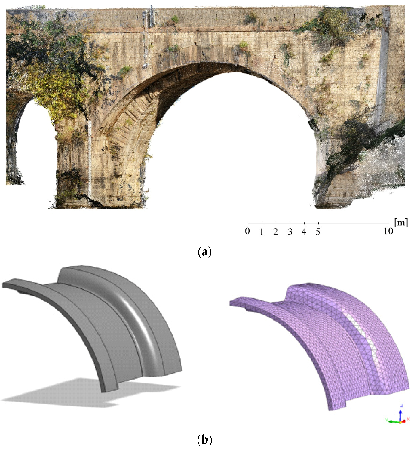
- Pepe, M.; Costantino, D.; Crocetto, N.; Garofalo, A.R. 3D modeling of roman bridge by the integration of terrestrial and UAV photogrammetric survey for structural analysis purpose. Int Arch Photogramm Remote Sens Spat Inf Sci 2019, 42, W17. [Google Scholar] [CrossRef] [Green Version]
- Karachaliou, E.; Georgiou, E.; Psaltis, D.; Stylianidis, E. UAV for mapping historic buildings: From 3D modelling to BIM. Int. Arch. Photogramm. Remote Sens. Spat. Inf. Sci. 2019, 42, 397–402. [Google Scholar] [CrossRef] [Green Version]
- Donato, V.; Biagini, C.; Bertini, G.; Marsugli, F. Challenges and opportunities for the implementation of h-bim with regards to historical infrastructures: A case study of the ponte giorgini in castiglione della pescaia (grosseto-italy). In Proceedings of the Geomatics & Restoration—Conservation of Cultural Heritage in the Digital Era, Florence, Italy, 22–24 May 2017. [Google Scholar]
- Themistocleous, K.; Agapiou, A.; Hadjimitsis, D. 3D documentation and BIM modeling of cultural heritage structures using UAVS: The case of the Foinikaria church. Int. Arch. Photogramm. Remote Sens. Spat. Inf. Sci. 2016, 42, 45. [Google Scholar] [CrossRef]
- Mishra, M.; Barman, T.; Ramana, G.V. Artificial intelligence-based visual inspection system for structural health monitoring of cultural heritage. J. Civ. Struct. Health Monit. 2022, 1–18. [Google Scholar] [CrossRef]
- Shabani, A.; Skamantzari, M.; Tapinaki, S.; Georgopoulos, A.; Plevris, V.; Kioumarsi, M. 3D simulation models for developing digital twins of heritage structures: Challenges and strategies. Procedia Struct. Integr. 2022, 37, 314–320. [Google Scholar] [CrossRef]
- Meschini, A.; Petrucci, E.; Rossi, D.; Sicuranza, F. Point cloud-based survey for cultural heritage. An experience of integrated use of range-based and image-based technology for the san francesco convent in monterubbiano. In Proceedings of the ISPRS Technical Commission V Symposium. Riva del Garda, Italy, 23–25 June 2014. [Google Scholar]
- Pepe, M.; Costantino, D.; Restuccia Garofalo, A. An efficient pipeline to obtain 3D model for HBIM and structural analysis purposes from 3D point clouds. Appl. Sci. 2020, 10, 1235. [Google Scholar] [CrossRef] [Green Version]
- Ebolese, D.; Brutto, M.L. Study and 3D survey of the Roman baths in the archaeological site of Lylibaeum (Marsala, Italy). IOP Conf. Ser. Mater. Sci. Eng. 2020, 949, 012103. [Google Scholar] [CrossRef]
- Nex, F.; Armenakis, C.; Cramer, M.; Cucci, D.A.; Gerke, M.; Honkavaara, E.; Kukko, A.; Persello, C.; Skaloud, J. UAV in the advent of the twenties: Where we stand and what is next. ISPRS J. Photogramm. Remote Sens. 2022, 184, 215–242. [Google Scholar] [CrossRef]
- UAV Drones Market. Available online: https://www.researchdive.com/8348/unmanned-aerial-vehicle-uav-drones-market (accessed on 29 September 2022).


| UAV Category | Max Takeoff Weight (Gross) | Normal Operation Altitude (ft) | Airspeed |
|---|---|---|---|
| Group 1 | <20 pounds (9.07 kg) | <1200 AGL (365.76 m) | <100 knots (<185.20 km/h) |
| Group 2 | 21–55 pounds (9.53–24.95 kg) | <3500 AGL (1066.8 m) | <250 knots (<463.00 km/h) |
| Group 3 | <1320 pounds (<598.74 kg) | <18,000 MSL (5486.4 m) | Any airspeed |
| Group 4 | >1320 pounds | <18,000 MSL (5486.4 m) | |
| Group 5 | >18,000 MSL |
| Lighter than Air | Heavier than Air | |||
|---|---|---|---|---|
| Flexible Wing | Fixed Wing | Rotary Wing | ||
| Unpowered | Ballon | Hang glider Paraglider Kites | Gliders | Rotor-kite |
| Powered | Airship | Paraglider | Propeller Jet engines | Single rotors Coaxial Quadrotors Multirotors |
| Strategy | Needs Base? | Uses Carrier-Phase? | Orbits and Clocks | Accuracy |
|---|---|---|---|---|
| SPP | no | no | broadcast | <5 m |
| PPP | no | yes | precise | cm (multi-freq), dm (single-freq) |
| RTK | yes | yes | broadcast | cm (multi-freq), dm (single-freq) |
| PPK | yes | yes | broadcast | cm (multi-freq), dm (single-freq) |
| Model | Manufacturer | Photo | Type | Weight (gr) | Endurance (min) | Max Speed (m/s) | Navigation | Camera |
|---|---|---|---|---|---|---|---|---|
| SwitchBlade-Elite + Sony RX1R II | Vision Aerial |  | Multicopter Tricopter | 2900 | 40 | 27 | RTK/PPK GPS + GLONASS | Sensor: Full frame BSI Resolution: 42 MP |
| Phantom 4 Pro v2.0 | DJI |  | Multicopter Quadricopter | 1388 | 30 | 20 | SPP/PPK GPS + GLONASS | Sensor: CMOS 1″ Resolution: 20 MP |
| PHANTOM 4 RTK | DJI |  | Multicopter Quadricopter | 1391 | 30 | 13.9 | RTK GPS + BeiDou + Galileo (Asia) GPS + GLONASS + Galileo (other regions) | Sensor: CMOS 1″ Resolution: 20 MP |
| Parrot Anafi | Parrot SA |  | Multicopter Quadricopter | 320 | 25 | 15 | SPP GPS + GLONASS | Sensor: CMOS 1/2.4″ Resolution: 20 MP |
| EVO II RTK | Autel Robotics |  | Multicopter Quadricopter | 1250 | 36 | 12.5 | RTK GPS + GLONASS+ BeiDou + Galileo | Sensor: CMOS 1″ Resolution: 20 MP |
| TYPHOON H3 | Yuneec and Leica |  | Multicopter Hexacopter | 1985 | 25 | 20 | SPP GPS + GLONASS + Galileo | Sensor: CMOS 1″ Resolution: 20 MP |
| Leica Aibot (customized DJI Matrice 600—Sony aR7ii) | Leica Geosystems |  | Multicopter Hexacopter | 11,200 | 24 | 18 | RTK GPS + GLONASS + Galileo | Resolution: 42.4 MP |
| UX5 HP | Trimble |  | Fixed-Wing | 2500 | 35 | 23.5 | PPK GPS + GLONASS | Sensor: CMOS 1″ Resolution: 36.4 MP |
| eBee X + SenseFly S.O.D.A. 3D | SenseFly, an AgEagle company |  | Fixed-Wing | 1300 1600 | 90 | 12.8 | RTK/PPK GPS + GLONASS | Sensor: CMOS 1″ Resolution: 20 MP |
| WingtraOne + Sony RX1R II | Wingtra AG |  | Multicopter and Fixed-Wing | 3700 | 59 | 12 | PPK GPS + GLONASS+ BeiDou + Galileo | Sensor: Full frame BSI Resolution: 42 MP |
| Location | Type | Flight Plan |
|---|---|---|
 |  Polygon | 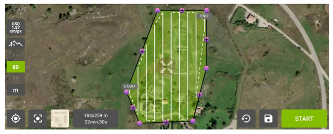 |
 Grid | 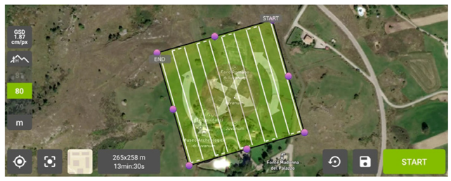 | |
 Double Grid | 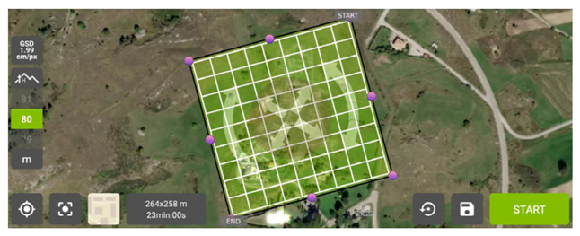 | |
 Circular |  |
| Software | Manufacturer | Ref. |
|---|---|---|
| PIX4Dcapture | Pix4D, Switzerland | [58] |
| UgCS UAV Mission Planning Software | Geometrics, U.S.A. | [59] |
| Uav Flight Map Pro Planner | Drone Emotions srl, Italy | [60] |
| DJI GS PRO | SZ DJI Technology Co. Ltd., China | [61] |
| Mission Planner | Created by Michael Oborne for the ArduPilot open-source autopilot project | [59] |
| eMotion, flight planning software for eBee drones | AgEagle Aerial Systems Inc., U.S.A. | [62] |
| Software | Description | Reference |
|---|---|---|
 | Agisoft Metashape is a professional software that can perform photogrammetric processing of digital images and videos and generate 3D spatial data for use in GIS applications, cultural heritage documentation, environmental monitoring, and more. It allows the generation and export in different formats of point clouds, textured 3D models, high-resolution orthophotos, digital elevation models, and contour lines, as well as the possibility of measuring distances, areas, and volumes thanks to tools integrated into the software. | [94,95] |
 | 3DF Zephyr software is produced in Italy and distributed by 3Dflow, a private consulting and software production company operating in the field of computer vision and image processing. It was founded in 2011 as a spin-off of the University of Verona and, in 2012, was recognised as a spin-off of the University of Udine. 3DF Zephyr is an automatic photogrammetry software that enables the creation of a 3D survey using photographs or digital videos. It allows us to create and export meshes and point clouds in the most common 3D formats, generate video animations, orthophotos, digital terrain models, sections, and contour lines, and calculate angles, areas, and volumes. | [96,97] |
 | ReCap software, owned by Autodesk, can convert digital images into 3D models or 2D drawings from aerial photogrammetric datasets or through close-up photogrammetry. The software makes it easy to create a point cloud or mesh ready for use with other CAD software or tools. AutoDesk ReCap Photo is part of the broader subscription programme, ReCap Pro is bundled with ReCap Pro as of 2019. ReCap Photo limits the amount of processing a single user can do by providing a limited number of ‘Cloud Credits’. | [98,99] |
 | Pix4D is a software developed by the Computer Vision Lab in Switzerland and implemented for both the image acquisition phase through mobile apps available for Android and iOS and the image processing phase. Pix4Dmapper generates point clouds, orthomosaics, and elevation models and is suitable for applications such as agriculture, surveying, architecture, and real estate by providing tools and instruments for measuring distances, areas, and volumes, enabling virtual inspections. | [100,101] |
 | PhotoModeler is essentially a phototriangulation programme capable of performing image-based modelling to produce 3D models and measurements. The software is also used for neighbourhood, aerial, and UAV photogrammetry (at relatively low altitudes) to perform measurements and modelling in agriculture, archaeology, architecture, biology, engineering, mining, storage volumes, etc. | [102,103] |
 | RealityCapture (RC) is photogrammetric software for creating 3D models obtained from terrestrial and/or aerial images or laser scans. In addition to point cloud measurement and filtering functions, it enables image registration, automatic calibration, polygon mesh production, texturing, digital model creation, and georeferencing and conversion of coordinate systems. The fields of use include everything from engineering and architectural applications in CH to land mapping, as well as visual effects (VFX) and virtual reality (VR) applications. | [104,105] |
 | Trimble Inpho is suitable for the high-precision transformation of aerial images into point clouds and surface models, orthophotos, and 3D digital models, using various modules that can be integrated into any photogrammetric workflow and production. It is a standard software solution for aerial photogrammetry that has been used for large metric mapping. | [106,107] |
 | WebODM is a user-friendly platform for producing point clouds, elevation models, textured models, and georeferenced maps using aerial digital images acquired from UAV systems. The software is a project of OpenDroneMap and supports multiple processing engines, currently ODM and MicMac. There is no cost to purchase a licence, but there is a one-off fee for installation and technical support. | [108,109] |
| Software | Description | Reference |
|---|---|---|
 | Regard3D is an SfM programme that can create 3D models of objects using a series of photographs taken from different viewpoints. The free, open-source software is available on various platforms (Windows, OS X, and Linux) and uses third-party tools and libraries. Several parameters enable the processing of models in a controlled and accurate manner. Furthermore, the actions necessary for processing the 3D model are implemented within the software in a logical and sequential manner. | [112,113] |
 | MicMac (Multi-Images Correspondances, Méthodes Automatiques de Corrélation) is a free and open-source photogrammetric product (Cecill-B license) used in various application areas such as cartography, environment, forestry, cultural heritage, etc. It allows the reconstruction of 3D models and the production of georeferenced orthophotos in local/global/absolute coordinate systems. | [114,115,116] |
 | Meshroom is a free and open-source 3D reconstruction software based on the AliceVision framework. AliceVision is a photogrammetric computer vision framework that provides 3D reconstruction and camera tracking algorithms. The project is the result of a university–industry collaboration to implement robust and high-performance algorithms in the field of computer vision in a nodal environment. | [117,118] |
 | COLMAP is a structure from motion (SfM) and multi-view stereo (MVS) pipeline with which it is possible, via the command line, to reconstruct 3D models from ordered and unordered image datasets. The tool has a simple graphical interface and automatic reconstruction tool; however, it includes command-line options for more advanced users. The programme is also equipped with numerous tools and settings, making it suitable for various reconstruction scenarios. | [119,120,121,122] |
 | VisualSFM is a GUI application designed by Changchang Wu, dedicated to 3D reconstruction. It integrates several algorithms required for sparse point cloud reconstruction, including SIFT on GPU (SiftGPU), multicore bundle adjustment, and towards linear-time incremental structure from motion.For the dense reconstruction phase, the application decomposes the problem into reasoned clusters and integrates Yasutaka Furukawa’s PMVS/CMVS algorithms. | [123,124] |
| Case Study | 3D Point Cloud | Model and Features of UAV Photogrammetry Process |
|---|---|---|
| 1 |  | 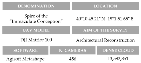 |
| 2 |  | 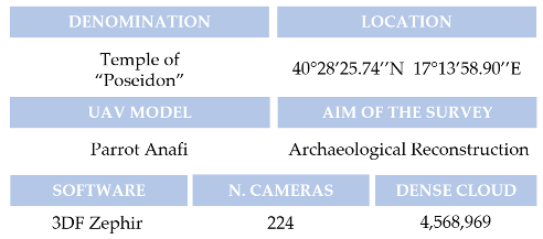 |
| 3 | 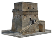 | 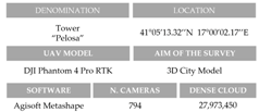 |
| 4 |  | 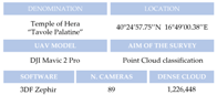 |
Publisher’s Note: MDPI stays neutral with regard to jurisdictional claims in published maps and institutional affiliations. |
© 2022 by the authors. Licensee MDPI, Basel, Switzerland. This article is an open access article distributed under the terms and conditions of the Creative Commons Attribution (CC BY) license (https://creativecommons.org/licenses/by/4.0/).
Share and Cite
Pepe, M.; Alfio, V.S.; Costantino, D. UAV Platforms and the SfM-MVS Approach in the 3D Surveys and Modelling: A Review in the Cultural Heritage Field. Appl. Sci. 2022, 12, 12886. https://doi.org/10.3390/app122412886
Pepe M, Alfio VS, Costantino D. UAV Platforms and the SfM-MVS Approach in the 3D Surveys and Modelling: A Review in the Cultural Heritage Field. Applied Sciences. 2022; 12(24):12886. https://doi.org/10.3390/app122412886
Chicago/Turabian StylePepe, Massimiliano, Vincenzo Saverio Alfio, and Domenica Costantino. 2022. "UAV Platforms and the SfM-MVS Approach in the 3D Surveys and Modelling: A Review in the Cultural Heritage Field" Applied Sciences 12, no. 24: 12886. https://doi.org/10.3390/app122412886