Article

Experimental Facility to Study the Threshold Characteristics of Laser Action at the p-s-Transition of Noble Gas Atom upon Excitation by 6Li(n,α)3H Nuclear Reaction Products

1
National Nuclear Center of the Republic of Kazakhstan, Kurchatov 071100, Kazakhstan
2
Institute of Atomic Energy Branch of National Nuclear Center of the Republic of Kazakhstan, Kurchatov 071100, Kazakhstan
3
School of Sciences and Humanities, Nazarbayev University, Astana 010000, Kazakhstan
4
Advanced Electronics Development Laboratory, Kazakh-British Technical University, Almaty 050000, Kazakhstan
5
Department of General Physics, Satbayev University, Almaty 050013, Kazakhstan
*
Author to whom correspondence should be addressed.
Appl. Sci. 2022, 12(24), 12889; https://doi.org/10.3390/app122412889
Submission received: 26 October 2022 / Revised: 12 December 2022 / Accepted: 13 December 2022 / Published: 15 December 2022
(This article belongs to the Section Optics and Lasers)

Abstract

:
Almost all experimental studies of the characteristics of nuclear-excited plasma formed by excitation of gaseous media with nuclear reactions products are conducted at pulsed nuclear reactors that differ in the composition and design of the core, the duration, flux and fluence of the neutron pulse, the impulse repetition frequency, the volume and configuration of the irradiation space. This paper presents a description of the experimental (methodical and hardware) base of the National Nuclear Center of RK (Kurchatov) to conduct experiments on studying the threshold characteristics of laser action at the p-s-transition of noble gas atoms upon 6Li(n,α)3H nuclear reaction products excitation in conditions of a pulsed nuclear IGR reactor. To conduct in-pile reactor experiments, a special experimental facility was developed and constructed. The experimental facility functionally includes: in-pile experimental device, a gas–vacuum system, information and measurement system consisting of a system for registering and controlling the temperature of the device housing, and a system for registering optical radiation. The paper also briefly describes the methodology of in-pile reactor experiments on the pulsed nuclear reactor.

1. Introduction

The study of optical radiation (laser and spontaneous) of nuclear-excited plasma formed by the nuclear reactions products is of interest for the development of energy output methods from a nuclear reactor by direct conversion into light energy [1,2,3], as well as for the creation of one of the methods for diagnostics of high-temperature plasma in fusion reactors [4]. Addressing the technical tasks related to the direct conversion of nuclear reaction energy into optical radiation will make it possible to create highly efficient energy-intensive sources of coherent and incoherent light radiation. The one-step nature of conversion of nuclear reaction energy into light study, bypassing the intermediate stages of thermal, mechanical and electrical energy, possesses a higher coefficient of efficiency, and the devices on its basis have low weight and dimensions characteristics compared to analogous devices of a traditional type. Excitation of gaseous media in experiments to study the optical radiation of nuclear-excited plasma conducted at nuclear reactors is realized, as a rule, by nuclear reactions products with thermal neutrons: 3He(n,p)3H, 10B(n,α)7Li, 235U(n,f)F [1,2,5]. Moreover, the isotopes (235U, 3He, or 10B) interacting with neutrons have to be in direct contact with the gaseous medium. There are two possible methods of using nuclear reaction energy for gas medium ionization and excitation. The first method involves the use of surface sources of charged particles. In this case, a thin layer of isotope 10B, 235U, or its compound 235UO2, 235U3O8 coats the inner surface of a working chamber. The second method involves the use of volume sources of charged particles, when a gaseous isotope or its compound, such as 3He, 235UF6, and 10BF3, are part of the working mixture. Along with the above-mentioned reactions used to ionization and excitation of gaseous medium, another reaction is used—the reaction of interaction of lithium-6 nuclei with thermal neutrons 6Li(n,α)3H. The relatively large mean free path of tritium nuclei in lithium (130 µm) and gaseous media (35 cm in atmospheric pressure of helium) allows for exciting large volumes of gases and providing a large value of power input nested in the gas compared to the reaction products with 10B.
Over several years, in NNC RK (Kurchatov, Kazakhstan), experiments were conducted at the IVG1.M stationary research reactor to study the luminescence of noble gases upon excitation of gas medium by 6Li(n,α)3H nuclear reaction products, which was practically not used before. Herewith, for the excitation of the gas medium, a surface method of using charged particles (liquid lithium stabilized in a capillary-porous system (CPS) was chosen.
In [6], the authors present a description of the experimental facility and design of an experimental device designed for in-pile experiments to investigate the spectral-luminescent characteristics of nuclear-excited plasma of noble gases, formed in the neutron irradiation field of the IVG.1M reactor, which provided the basis for the development of a new experimental facility described in detail in this manuscript.
The main results of the reactor experiments performed on an IVG.1M stationary reactor are given in [7,8,9,10].
At present time, the experiments to study the direct conversion of nuclear energy into the energy of optical radiation at the IGR pulsed research reactor are ongoing. The purpose of these experiments at the IGR reactor is to study the possibility of obtaining laser action at the p-s-transitions of noble gases atoms in the near infrared region of the spectrum (from 0.7 to 1 µm) upon excitation by the 6Li(n,α)3H nuclear reaction products. Lithium serves as a source of laser mixture pumping with products of 6Li(n,α)3H nuclear reaction, also effectively deactivating lower 1s-levels [8].
This paper describes the experimental (methodical and hardware) basis for conducting experiments to study the threshold characteristics of laser action at the p-s-transition of noble gas atom upon 6Li(n,α)3H nuclear reaction products’ excitation in conditions of a pulsed IGR nuclear reactor.
Thus, the results of scientific research can find application in the creation of nuclear power plants that generate laser or spontaneous optical radiation, as well as in systems for monitoring the parameters of nuclear reactors [11,12,13].

2. Experimental Technique

2.1. Neutron Flux Source, IGR Reactor

An IGR pulsed nuclear reactor (Kazakhstan, Kurchatov) is used as a source of neutron flux.
An IGR pulsed research reactor is a homogenous, uranium-graphite, high-temperature, self-quenching, thermal neutron reactor [14,15]. Among pulsed reactors, IGR has the highest thermal neutron fluence and integral gamma radiation dose in experimental cavity. Maximal thermal neutron flux density in the experimental cavity with a diameter of 228 mm and height of 3825 mm—7 × 10¹⁶ n/cm2s, minimum half-width of pulse duration—is 0.12 s.
The main modes of IGR reactor operation are uncontrolled pulsed mode in Figure 1a (mode of self-quenching neutron burst, mode “Burst”) and controlled mode (mode “Pulse”) in Figure 1b.
To carry out self-quenching mode of neutron burst (mode “Burst”), the reactor is given some positive reactivity that determines the shape, amplitude, and half-width of burst; burst quenching is due to the negative temperature effect of the reactivity.
Controlled mode (“Pulse” mode) is carried out by an automatic power regulator that controls movement of working elements of safety control system (SCS) upon the given law. The form, amplitude (power level) and duration of the controlled mode can be very different and are determined by the test tasks based on the condition of maximum energy release in reactor core that is 5.2 GJ, corresponding to thermal neutrons fluence up to 3.7 × 1016 cm−2 in a central experimental channel (CEC).
Experimental studies of threshold characteristics of coherent optical radiation during excitation of gas mixtures by products of nuclear reaction 6Li(n,α)3H are carried out in an IGR reactor central experimental channel in “Burst” mode.
Table 1 presents calculated values of IGR reactor operation modes during experiments in “Burst” mode.
Registration of IGR reactor parameters (position of control elements in initial stage before and during startup, currents of CPS ionization chambers, reactor core measurement) is carried out by a standard technological control system of IGR RRC.

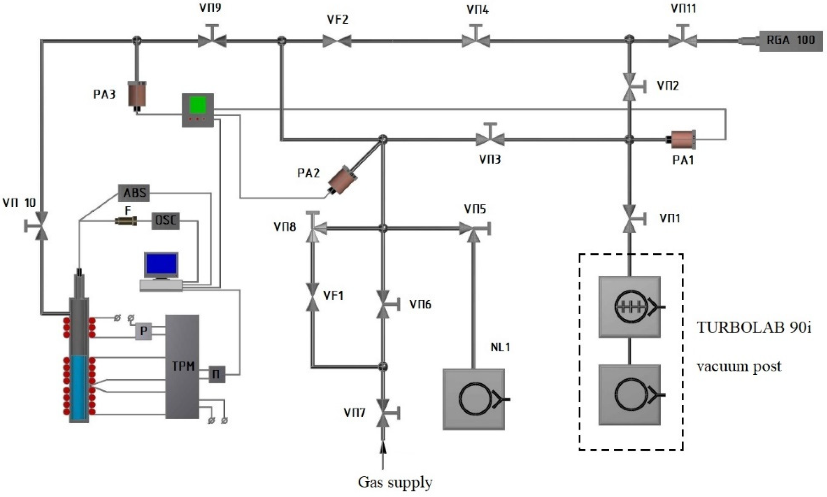
2.2. Experimental Facility

The experiments to study spectral-temporal characteristics of nuclear-excited plasma formed by nuclear reaction products 6Li(n,α)3H are conducted using a specially created experimental facility, located in an IGR reactor hall. An experimental facility is designed for gaseous mixtures formation with specified parameters within the scope of experimental irradiation device during the experiments on the study of spectral-temporal characteristics of coherent optical radiation. The functional scheme of an experimental facility is shown in Figure 2.
The experimental facility includes:
  • Gas–vacuum system;
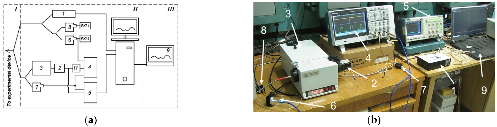
  • Information measuring system (IMS);
  • Experimental irradiation device (ID).
The gas–vacuum system of the experimental facility allows for creating necessary vacuum conditions within the scope of experimental ID for reactor experiments (lower limit of pumping rate of ID is 10−4 Torr; upper limit of the pressure of investigated gas mixture is 800 Torr. The main structural elements of gas–vacuum system of the facility are:
  • Turbomolecular pumping system (TURBOLAB 90i 63ISO-K/SC7plus/F/N vacuum post);
  • Shut-off valve (vacuum valves, breakers);
  • Pressure measurement means (vacuum sensors);
  • Quadrupole probe (sensor) of mass-spectrometer RGA-100;
  • Pipelines connecting elements of a gas–vacuum system.
The components of the gas–vacuum system of experimental facility are connected to each other using KF-type quick-release couplings. The quadrupole probe of the mass-spectrometer is connected with a vacuum tract through the CF type flange connection.
The information and measuring system (IMS) provides monitoring of parameters and facility control during its preparation for experiments, as well as recording of optical signals. IMS involves three subsystems:
  • System of temperature adjustment and registration of ID housing (provides heating and stabilization of ID housing temperature set during annealing at the preliminary stage of experiments);
  • Optical system of light signal registration (provides registration of light radiation within a wavelength range from 200 nm to 2500 nm, occurring in a volume of ID active cell);
  • Mass-spectrometric system of gas analysis (serves for gas phase identification in ID volume and registration of gas partial pressure in real time mode during preparation for experiments).
Table 2 presents a list of IMS parts and their parameters.
The personal computer is used for facility parameters’ registration and control, installed in a pre-reactor room, which is controlled by another personal computer, located in an IGR reactor control room. Figure 3 shows a schematic diagram of the optical signal recording system and a photograph of the optical signal recording equipment during calibration located in the pre-reactor room of the IGR reactor.
The scheme in Figure 3a shows premises where equipment is placed with I, II, III figures: I—IGR reactor (reactor building); II—pre-reactor room; III—control room of IGR reactor.
The experimental irradiation device (ID) is made considering study task and character of technical maintenance, associated with these tasks. For that, the ID shall provide the possibility of experimental cells placement, with the surface source of charged particles (lithium CPS) at the level of the IGR reactor core center, adjustment, and the maintaining of the temperature regime under the survey of ID experimental cell housing. The next subsection presents a detailed description of the developed ID.

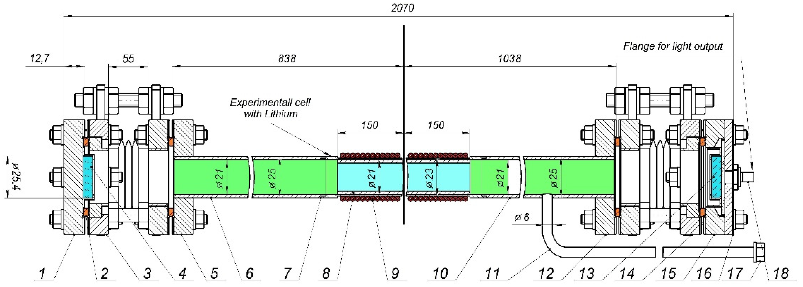
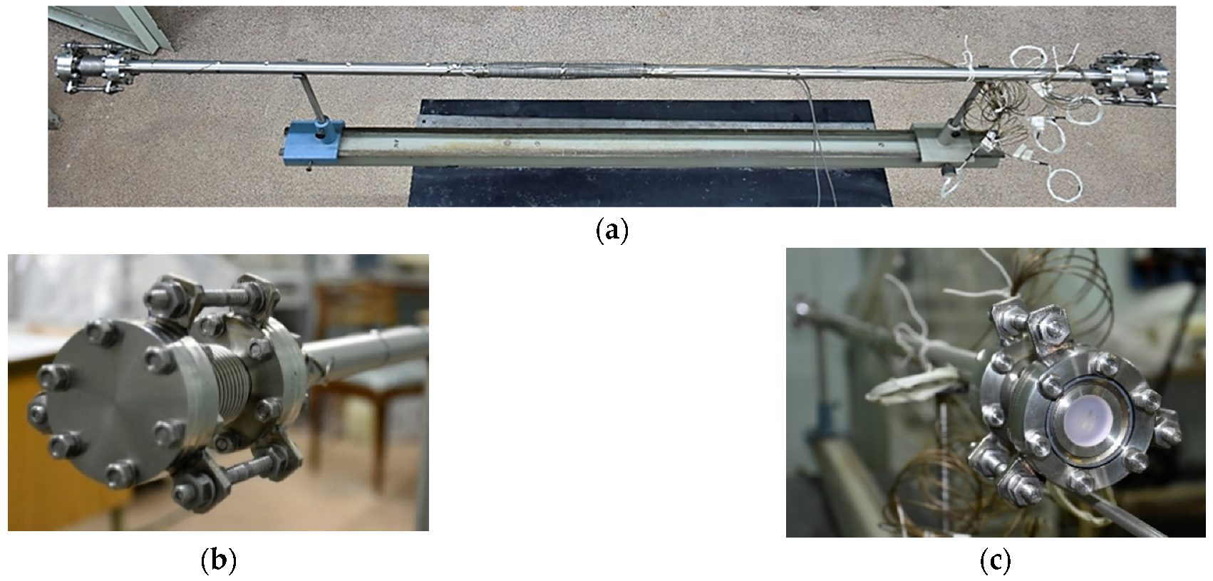
2.3. Experimental Irradiation Device with a Lithium Source of Gas Media Excitation

An in-pile experimental irradiation device with a surface source of charged particles has been specially developed for reactor experiments conduction. For the developed design of the irradiation device, a patent for utility model of the Republic of Kazakhstan was issued and obtained [16]. Natural lithium is used as a source of charged particles in the current structure, stabilized in metal CPS, and applied on the inner surface of the ID experimental cell (natural composition of lithium isotopes: 6Li (7.5%) + 7Li (92.5%). Figure 4 presents a draft of an experimental irradiation device with a lithium source of gas medium excitation.
The main structural elements of ID are:
  • experimental cell of ID;
  • light flux output node.
The experimental cell is a pumped volume of irradiation device, in which a stainless grid is mounted and filled with lithium (lithium CPS). The experimental cell housing is made of the tube, Ø 25 × 2 mm. In the lithium CPS attachment area, the outer diameter of the tube is reduced down to 23 mm. The material of the tube is corrosion-resistant steel 12Cr18Ni10Ti.
Lithium CPS represents a cylinder with a height of 300 mm made of a mesh, 0.355 mm × 0.355 mm in a size, located at the inner surface of the experimental cell. The mesh material is also a corrosion-resistant steel 12Cr18Ni10Ti.
At the ends of ID experimental cell (upper and lower parts), specially produced aligners are mounted presenting a sylphon (compensator) with flange connector CF 40. A standard (factory-made) plug CF 40 is used as a counter flange to the sylphon in the lower part of the ID experimental cell. A concave silver coated mirror is tightly installed on the inner side of the plug (mirror thickness is 6 mm; diameter—25.4 mm). The standard (factory-made) vacuum window with flange connection CF 40 is used as a counter flange to the sylphon in the upper part of experimental cell. A wide-band dielectric mirror on a quartz substrate (mirror thickness is 6 mm; diameter is 25.4 mm) is tightly installed before the vacuum window. The aligners with installed mirrors are necessary for mirrors adjustment.
To provide temperature regimes required during the preparation of ID for experiments, an ohmic heater is installed at the external side of the ID experimental cell middle part.
To control and record the temperature of ID experimental cell housing at different heights, six frame thermocouples of ChAl type (chromel-aluminum thermocouples) are installed on the external side:
  • On the lower part of the cell near the aligner flange (1 pc.);
  • On the middle part of the ID experimental cell;
  • At the level of the lower end of lithium CPS (1 pc.);
  • At the level of the central part of lithium CPS (2 pcs.);
  • At the level of the upper end of lithium CPS (1 pc.);
  • On the upper part of the cell;
  • At the level of pumping pipeline joints (1 pc);
  • Near the upper flange of aligner (1 pc.).
The light output node is a flange plug with a centrally mounted (chopped in) collimating lense (74-UV-HT-VAC, spectral range 190–2500 nm). A flange plug with an internal thread for the collimating lense is made of duralumin and is attached directly to the flange of the vacuum window.
Gas mixture pumping and supply into the ID cell is carried out through a pipeline, made of pipe Ø 8 × 1, welded by argon-arc welding in the upper part of experimental cell. (Material: corrosion-resistant steel 12Cr18Ni10Ti) KF 16 quick-connection nipple is mounted at the outlet side of the pipeline in order to connect with gas–vacuum system of experimental facility.
Figure 5 presents photos of a manufactured ID.
The irradiation device has been mounted on the experimental facility and checked for leak tightness using an RGA-100 spectrometer by purging helium on the welded and flanged joints of ID. Leak-in the ID volume is composed of not more than 3.3·10−16 Pa·m3/s, which corresponds to the vacuum requirements set for the manufactured device to be used during in-pile reactor experiments.

3. Results and Discussion

The methodical reactor experiments for tuning the methods for measuring the spectral and spectral-temporal characteristics of gas plasma radiation at IGR reactor have been conducted using the in-pile device similar to the abovementioned ID in design, but without the use of mirrors. The experiments were carried out to study the spectral-temporal characteristics of such gaseous media, as argon (Ar) as well as a mixture of gases He–Ar upon excitation by the 6Li(n,α)3H nuclear reaction products. Optical radiation was registered using the QEPro-abs optical spectrometer, PMT module, connected to oscilloscope, DET100A and DET025A photodiodes for the visible spectra regions and InGaAs-photodiode for an infrared region according to the scheme presented in Figure 3a. As the experimental device with lithium source of gaseous media excitation was primarily designed to register laser radiation, a lens to gather the light flux was located at a distance of about 1.2 m from the reactor core so the intensity of lines on spectrometer were insignificant during the study of spontaneous radiation.
Argon at a pressure of 305 Torr was irradiated in the “Burst” mode with a duration of 0.13 s and a power of 6.6 GW (Figure 6), which corresponds to a thermal neutron flux of 4.6∙1016 n/cm2s.
The argon emission spectrum is shown in Figure 7. The spectrum shows that two lithium lines predominate at 610.4 and 670.8 nm (Figure 7). The argon lines are at the background level. Optical radiation intensity vs. time curve (Figure 6) almost follows the reactor power vs. time with a shift of about 15–20 ms. It seems that the shift in time is explained by thermal radiation of the lithium layer due to the additional heating occurred under irradiation with thermal neutron flux and further cooling. Argon radiation pulse duration at 750.4 nm wavelength (≈95 ms, Figure 8) is slightly shorter than the duration of pumping pulse and the integral optical radiation flux in the sensitivity range of the Si-photodiode (Figure 6). Radiation maximum in the infrared area is also shifted by approximately 50 ms with respect to the maximum at 750.4 nm (Figure 8).
The spectrum was sharply dominated by two lines: 750.4 nm and 912.3 nm in the He(702 Torr) + Ar (1.7 Torr) mixture (Figure 9). High intensity of 750.4 nm line is explained by the low quenching with helium level 2p1. The prevailing of line 912.3 nm is caused by the fact that the transition begins from the lowest level 2p10, to which excitation of all high-lying levels is transferred during the quenching by helium and own gas. The weak lines on 810.3 and 842.5 nm are also irradiated from the low-lying levels 2p7 and 2p8.
Thus, it can be concluded from the emission spectrum that the He–Ar mixture offers a chance to achieve laser action at the 2p1-1s2 transition.
Similar research has been carried out by other research organizations involved in nuclear-pumped gas lasers. In [17], for instance, the authors present a description of the experimental setup and a measurement technique, as well as the results of the spectral-luminescent properties of noble gases and their mixtures, excited by uranium fission fragments, conducted at the VIR-2M water pulse nuclear reactor. In [18], the authors present an experimental setup configuration and lasing experiments results on uranium fission fragments pumping of gas lasers conducted at the BARS-6 fast burst reactor. In [19], the authors reported an experimental investigation of lasing action, due to a 4p-4s transition of Ar atom (λ = 1149 nm), upon the He–Ar mixture pumped by uranium fission fragments.

4. Conclusions

This paper presents a description of a manufactured experimental facility and in-pile irradiation device designed to conduct experiments for studying the threshold characteristics of laser action at the p-s-transition of noble gas atom upon 6Li(n,α)3H nuclear reaction products excitation in conditions of a pulsed nuclear IGR reactor. The results of methodical reactor experiments carried out on the experimental device using ID with a lithium source of excitation of gas mixtures are briefly presented. The experiment findings showed the operability of the created device and proposed design of the ID. The emission spectrum of the gas mixture excited by the products of the 6Li(n,α)3H nuclear reaction in the “Burst” reactor operating mode obtained due to methodical experiments demonstrated good prospects of using an He–Ar gas mixture to achieve the laser action in transitions 2p1-1s2.

5. Patents

Patent for utility model “Irradiation device for conducting experiments on pulsed graphite reactor”, Authors: Batyrbekov E.G., Khassenov M.U., Samarkhanov K.K., Gordienko Yu.N., Ponkratov Yu.V., Tulubayev Ye.Yu., Bochkov V.S. No. 7162 dated 03/06/2022 RSE “National Institute of Intellectual Property” of the Ministry of Justice of the Republic of Kazakhstan, 2022.

Author Contributions

Conceptualization, M.K.; methodology, Y.G.; formal analysis, M.K.; investigation, M.K. and K.S.; resources, A.K., A.M. and V.T.; data curation, V.B.; writing—original draft preparation, M.K.; writing—review and editing, I.E.K. and K.S.; visualization, K.S. and Y.G; supervision, E.B.; project administration, E.B.; funding acquisition, E.B. All authors have read and agreed to the published version of the manuscript.

Funding

This research was funded by the Committee of Science of the Ministry of High Education and Science of the Republic of Kazakhstan, Grant No. AP08856017.

Institutional Review Board Statement

Not applicable.

Informed Consent Statement

Not applicable.

Data Availability Statement

Not applicable.

Acknowledgments

The authors express their gratitude to the IGR reactor staff of the Institute of Atomic Energy NNC RK for their assistance in preparing and conducting the experiments.

Conflicts of Interest

The authors declare no conflict of interest. The funders had no role in the design of the study; in the collection, analyses, or interpretation of data; in the writing of the manuscript; or in the decision to publish the results.

References

  1. Mel’nikov, S.P.; Sinyanskii, A.A.; Sizov, A.N.; Miley, G.H. Lasers with Nuclear Pumping; Springer: New York, NY, USA, 2015; p. 455. [Google Scholar]
  2. Prelas, M. Nuclear Pumped Lasers; Springer International Publishing: Cham, Switzerland, 2016; p. 417. [Google Scholar]
  3. Batyrbekov, E. Converting nuclear energy into the energy of coherent optical radiation. Laser Part. Beams 2013, 31, 673–687. [Google Scholar] [CrossRef]
  4. Apruzzese, G.M.; Apicella, M.L.; Maddaluno, G.; Mazzitelli, G.; Viola, B. Spectroscopic measurements of lithium influx from an actively water-cooled liquid lithium limiter on FTU. Fusion Eng. Des. 2017, 117, 145–149. [Google Scholar] [CrossRef]
  5. Mis’kevich, A.I. Visible and near-infrared direct nuclear pumped lasers. Laser Phys. 1991, 1, 445–481. [Google Scholar]
  6. Gordienko, Y.; Batyrbekov, E.; Skakov, M.; Ponkratov, Y.; Khasenov, M.; Zaurbekova, Z.; Barsukov, N.; Kulsartov, T.; Tulubayev, Y. Experimental facility for reactor experiments on study of spectral-luminescent characteristics of nuclear-excited plasma. J. Phys. Conf. Ser. 2016, 747, 012012. [Google Scholar] [CrossRef] [Green Version]
  7. Gordienko, Y.; Khasenov, M.; Batyrbekov, E.; Samarkhanov, K.; Ponkratov, Y.; Amrenov, A. Emission of noble gases and their mixtures with lithium excited by products of 6Li(n,α)3H nuclear reaction. Laser Part. Beams. 2019, 37, 18–24. [Google Scholar] [CrossRef]
  8. Batyrbekov, E.; Khasenov, M.; Gordienko, Y.; Samarkhanov, K.; Ponkratov, Y. Optical radiation from the sputtered species under gas excitation by the products of the 6Li(n,α)3H nuclear reaction. J. Lumin. 2020, 220, 116973. [Google Scholar] [CrossRef]
  9. Samarkhanov, K.; Khasenov, M.; Batyrbekov, E.; Kenzhina, I.; Sapatayev, Y.; Bochkov, V. Emission of Noble Gases Binary Mixtures under Excitation by the Products of the 6Li(n, α)3H Nuclear Reaction. Sci. Technol. Nucl. Install. 2020, 2020, 8891891. [Google Scholar] [CrossRef]
  10. Samarkhanov, K.; Khasenov, M.; Batyrbekov, E.; Gordienko, Y.; Baklanova, Y.; Kenzhina, I.; Tulubayev, Y.; Karambayeva, I. Optical Radiation from the Sputtered Species under Excitation of Ternary Mixtures of Noble Gases by the 6Li(n,α)3H Nuclear Reaction Products. Eurasian Chem. Technol. J. 2021, 23, 95–102. [Google Scholar] [CrossRef]
  11. Lamotte, M.; de Izarra, G.; Jammes, C. Development and first use of an experimental device for fission-induced spectrometry applied to neutron flux monitoring. Nucl. Instrum. Methods Phys. Res. A Accel. Spectrom. Detect. Assoc. Equip. 2020, 953, 163236. [Google Scholar] [CrossRef]
  12. Lamotte, M.; de Izarra, G.; Jammes, C. Pulse-reactor core monitoring with an innovative optical neutron detector. Nucl. Instrum. Methods Phys. Res. A Accel. Spectrom. Detect. Assoc. Equip. 2021, 995, 165086. [Google Scholar] [CrossRef]
  13. Lamotte, M.; de Izarra, G.; Jammes, C. Design and irradiation test of an innovative optical ionization chamber technology. Nucl. Instrum. Methods Phys. Res. A Accel. Spectrom. Detect. Assoc. Equip. 2020, 968, 163945. [Google Scholar] [CrossRef]
  14. Vityuk, V.; Vurim, A. Method for determining the energy parameters in pulse reactor experiments. Ann. Nucl. Energy 2019, 127, 196–203. [Google Scholar] [CrossRef]
  15. Tskhe, V.K.; Mukhamedov, N.Y.; Gaydaychuk, V.A.; Kozlovskiy, Y.V.; Gradoboev, A.V. The method of the reactivity margin calculation required for the IGR reactor start-up in the “Pulse” mode. Ann. Nucl. Energy 2022, 168, 108875. [Google Scholar] [CrossRef]
  16. Batyrbekov, E.G.; Khassenov, M.U.; Samarkhanov, K.K.; Gordienko, Y.N.; Ponkratov, Y.V.; Tulubayev, Y.Y.; Bochkov, V.S. Patent for Utility Model “Irradiation Device for Conducting Experiments on Pulsed Graphite Reactor”. No. 7162, 3 June 2022 G21C 23/00 (2006.01); Bulletin No. 22; 3 June 2022. Available online: https://kazpatent.kz/en/content/poleznaya-model-03062022 (accessed on 3 June 2022).
  17. Abramov, A.; Gorbunov, V.; Melnikov, S.; Mukhamatullin, A.; Pikulev, A.; Sinitsyn, A.; Sinyanskii, A.; Tsvetkov, V. Luminescence of nuclear-induced rare-gas plasmas in near infrared spectral range. In Proceedings of the Atomic and Molecular Pulsed Lasers VI, Tomsk, Russia, 12–16 September 2005; SPIE Press: Bellingham, DC, USA, 2006; Volume 6263, p. 626312. [Google Scholar] [CrossRef]
  18. Barzilov, A.; Bokhovko, M.; Gulevich, A.; Dyachenko, P.; Kachanov, B.; Kononov, V.; Kukharchuk, O.; Pashin, E.; Regushevsky, V.; Zrodnikov, A. Theoretical and experimental studies of gaseous laser pumped by a twin-core fast burst reactor. In Proceedings of the AIP Conference Proceedings, Monterey, CA, USA, 13–18 April 1997; American Institute of Physics: College Park, MD, USA, 1997; Volume 406, pp. 351–358. [Google Scholar] [CrossRef]
  19. Mel’nikov, S.; Sinyanskiĭ, A. Quasi-cw lasing due to the 4p–4s transition of the argon atom in an He–Ar laser pumped by uranium fission fragments. Sov. J. Quantum Electron. 1991, 21, 1332. [Google Scholar] [CrossRef]
Figure 1. IGR Reactor Operation Modes: (а) mode “Burst”; (b) “Pulse”.
Applsci 12 12889 g001
Figure 2. Scheme of experimental facility: NL 1—spiral pump; VP1…VP10—vacuum valves; PA1…PA3—pressure sensors; VF1, VF2—leakage valve; RGA 100—quadrupole probe/sensor (mass-spectrometer RGA-100); ABS—optical spectrometer; F—photo detector; OSC—oscilloscope; C—controller for pressure sensor; R—solid state relay for voltage regulation; P—converter of interfaces RS-485 <-> USB with galvanized isolation; ТРМ—two-channel regulator with universal input and RS.
Applsci 12 12889 g002
Figure 3. Optical system of facility: (a) scheme of optical recording system; (b) equipment for optical signal registration during calibration: 1—QE-Pro-abs optical spectrometer, 2—PMT module, 3—MDR-204 monochromator, 4—TBS2204B oscilloscope, 5—TPS2012 oscilloscope, 6—DET100A photo detector, 7—DET25A/M photo detector, 8—InGaAs photo detector, 9—PC for experimental data recording, PXI1, PXI2—system lines, technological control of IGR reactor.
Applsci 12 12889 g003
Figure 4. Experimental irradiation device, designed for in-pile experiments: 1—flange plug; 2—copper gasket; 3—the lower aligner of ID cell; 4—silver-coated mirror; 5—counter flange CF40 of the lower aligner of ID cell; 6—housing, the lower part of the experimental ID cell; 7—housing, the middle part of experimental cell; 8—lithium CPS; 9—ohmic heater; 10—housing, the upper part of experimental cell; 11—path for gas mixture supply and pumping; 12—counter flange CF40 of the upper aligner of ID cell; 13—dielectric mirror; 14—upper aligner of ID cell; 15—vacuum window with CF40 flange; 16 –flange plug; 17—nipple of KF 16 quick connection; 18—collimating lense.
Applsci 12 12889 g004
Figure 5. Irradiation device for experiments at IGR reactor: (a) ID assembled; (b) the lower aligner of ID with flange plug; (c) the upper aligner with vacuum window.
Applsci 12 12889 g005
Figure 6. Time dependence of reactor power and signal from Si–photodiode DET100A. Argon is at a pressure of 305 Torr, and lithium layer temperature before reactor startup is 710 K.
Applsci 12 12889 g006
Figure 7. Emission spectrum in argon medium. Initial pressure of Ar is 305 Torr, and lithium layer temperature before the reactor start-up is 710 K.
Applsci 12 12889 g007
Figure 8. Oscillogram of PMT Signals, (1), and InGaAs Photodetector (2). Gas–argon under pressure of 305 Torr, and lithium layer temperature before reactor start-up is 710 K. The scale is expanded vertically in 104 for the line (2).
Applsci 12 12889 g008
Figure 9. Spectrum of He(702 Torr) + Ar (1.7 Torr) mixture radiation. Lithium layer temperature before reactor start up is 386 K.
Applsci 12 12889 g009
Table 1. Calculated values of IGR Reactor Operation Mode during Experiments in “Burst” Mode.
Parameter of ReactorValue of Reactor
Initial reactivity leapNot more 5 βeff
Maximal power of reactor in “BURST” modeNot more 10 GW
Maximal neutron flux density in IGR CEC~7 × 10¹⁶ n/(cm2∙s)
Table 2. Parts of the experimental facility IMS.
PartsType (grade)Parameters
Optical fiberBIF600-VIS + NIRspectral range: 400–2500 nm
P-600-10-UV + VISspectral range: 300–1100 nm
P-600-10-VIS + NIRspectral range: 400–2100 nm
Optical spectrometerQE-Pro-absspectral range: 200–950 nm
High-Speed Fiber-Coupled Detectorssilicon detector (DET100A)Rise time 35 ns,
spectral range: 320 nm–1100 nm;
silicon detector (DET25A/M)Rise time 1 ns
spectral range 400 nm–1100 nm
Indium–gallium detector
(DET08CFC/M–InGaAs)
Bandwidth 5 GHz, rise time 70 ps
spectral range: 800 nm up to 1700 nm
PMT modulePDM02-9113W-CNspectral range: 280–850 nm;
MDR-204 monochromator spectral range: 190–5000 nm
oscilloscopeTektronix TBS 2204B200 MHz Bandwidth
Tektronix TPS 2012100 MHz Bandwidth
quadrupole mass-spectrometerRGA-100measured mass range is from 1 a.m.u.
up to 100 a.m.u.
pressure sensorVSR53Dworking range: 1·10−4–750 Torr
MTM 9Dworking range: 1·10−9–750 Torr
pressure sensor controllerVD10Power supply: alternating current, voltage from 95 V to 265 V, 50/60 Hz
Consumed power–25 W
Publisher’s Note: MDPI stays neutral with regard to jurisdictional claims in published maps and institutional affiliations.

