Article

Edge Restoration of a 3D Building Model Based on Oblique Photography

1
Key Laboratory of Ministry of Education on Safe Mining of Deep Metal Mines, Northeastern University, Shenyang 110819, China
2
Institute for Geoinformatics & Digital Mine Research, Northeastern University, Shenyang 110819, China
*
Author to whom correspondence should be addressed.
Appl. Sci. 2022, 12(24), 12911; https://doi.org/10.3390/app122412911
Submission received: 8 November 2022 / Revised: 12 December 2022 / Accepted: 12 December 2022 / Published: 15 December 2022

Abstract

:
Unmanned aerial vehicle (UAV) oblique photography technology is widely used in a variety of fields because of its excellent efficiency, realism, and low cost of manufacturing. However, due to the influence of lighting, occlusion, weak textures, and other factors in aerial images, the modeling results can have the problem of an incorrect structure that is inconsistent with the real scene. The edge line of a building is the main external expression of its structure. Whether the edge line is straight or not will directly affect the realism of the building, so the restoration of the edge line can improve the realism of the building. In this study, we proposed and developed a method for the restoration of the edge line of a 3D building model based on triangular mesh cutting. Firstly, the feature line of the edge line was drawn using human–computer interaction, and axis-aligned bounding box (AABB) collision detection was carried out around the feature line to determine the triangular patches to be cut. Then, the triangular cutting algorithm was used to cut the triangular patches projected onto the plane. Finally, the structure and texture of the 3D building model were reconstructed. This method allowed us to actualize the physical separation of continuous triangulation; the triangulation around the edge line was cut, and the plane was fitted. This method was able to improve cutting accuracy and edge flatness and enhance the edge features of buildings and the rendering quality of models. The experimental results showed that the edge restoration method proposed in this paper is reliable and that it can effectively improve the building rendering effect of a 3D building model based on UAV oblique photography and can also enhance the realism of the model.

1. Introduction

With the rapid development of the social economy and the acceleration of urban informatization, the digital city has created the conditions for the harmonious development of cities, and the foundation of the digital city is a city with a three-dimensional (3D) model [1]. With the increasingly broad application of 3D GIS [2,3], urban 3D models are widely used in urban maps, digital cities, and virtual campuses [4]. Three-dimensional reconstruction of oblique photogrammetry uses multiple optical sensors to collect data from the target area from multiple angles simultaneously, which can restore the structure of the ground object quickly and efficiently and attach the real texture so as to provide real scene information of the ground object. This effectively reduces the cost of modeling, especially in the field of 3D city construction [5] and has become one of the main means of city modeling [6]. At present, the 3D reconstruction technology of oblique photogrammetry is widely used in various fields, such as positioning services [7], disaster assessment [8], and archaeological research [9], taking advantage of its high efficiency, wide range, and strong sense of reality. The process of acquiring a 3D model by UAV includes the steps of acquiring aerial images, position and orientation system (POS) data and control point data in the field, automatically performing aerial triangulation and aerial triangulation encryption, dense matching, the construction of triangulation networks, and texture mapping [10]. The production process of an oblique photography 3D model is characterized by full automation, so the modeling quality is greatly affected by the oblique image. The 3D model is automatically constructed, it is only a continuous three-dimensional surface model of the overall scene without semantic topological relations [11], resulting in an incorrect structure of the 3D model that is inconsistent with the real scene, which is only suitable for simple applications such as macroscopic visual browsing of the overall scene, and cannot meet the needs of applications such as refined city management [12,13]. The edge line is the most obvious part of the building. Whether the edge line is straight or not will directly affect the realism of the building. In many cases, the realism of the 3D building model and the requirements of further application analysis can be met only by restoring the edge line [14].
Regular edge lines can effectively improve the rendering effect and realism of building models. To restore the building edge line of a 3D model, the feature line of the edge line needs to be drawn. Currently, there are two main feature line extraction methods for existing 3D models: the surface-based extraction method and the edge-based extraction method. For the surface-based extraction method, there are mainly two types. One is by starting from multiple seed points; each seed point grows with the same curvature as that of the surface, and then the intersection line between these surfaces is calculated, with the obtained intersection line being the feature line [15,16,17]. The other is to extract feature points and feature edges by calculating the curvature of local areas on the model surface and then connecting them through certain methods to obtain complete feature lines [18,19]. Surface-based feature extraction methods rely heavily on noise-sensitive differential invariants such as surface curvature [20], so these methods are generally only applicable to smooth 3D models with relatively uniform points and faces, which are generally constructed manually. It is difficult to take into account the small noise in complex and rough 3D models of oblique photogrammetry using this type of method. Because of the large computation and low speed, it is also difficult to extract the feature lines of a model quickly. The extracted results are not based on the edges of the existing triangles, so it is not convenient for use in directly restoring the 3D model of oblique photogrammetry [21]. For the edge-based extraction method, the feature edges of the model are extracted by estimating the differential quantity of the model. A common means includes calculating the dihedral angle of the triangle edge. After the feature edges are extracted, the model feature lines are obtained by setting a certain threshold to connect the edges that meet the recognition conditions to form a closed loop. The method is simple and fast but poorly targeted, and the accuracy of the extraction results is low. A series of subsequent processes are also required to filter the extracted results [22]. In view of the serious defects and shortcomings of the above-mentioned existing methods in the extraction of feature lines of oblique photogrammetry 3D models with dense data, complex structures, and obvious noise, we first proposed a fast and intelligent feature line detection method of 3D models based on AABB (axis-aligned bounding box) collision detection.
The existing edge line restoration methods for 3D models are mainly as follows. (1) Feature points are selected using an interactive method, and the selected feature points are fitted to the target line to complete the restoration. This method is a semi-automatic method that completes the edge line restoration with less interaction. However, the human interaction of this method is complex, and it takes a long time when there are many triangles and cutting surfaces. (2) Automatic identification and selection of feature vertices by adding limit lines or edges, and completing the edge restoration of the 3D model by moving the selected vertices to the corresponding limit lines or edges. This method is highly automated. However, due to the complex and noisy 3D model of oblique photogrammetry, the automatic selection of vertices to be modified is often not ideal, which makes the restoration results far from expected [23,24]. (3) Based on the topological relationship of triangulation, the shortest path method is used to search for the edge feature line, and the auxiliary surface is used to reduce the noise to improve the restoration effect. The edge restorations of a 3D model based on continuous triangulation can be achieved [25]. However, this method of extracting edge features lines requires a lot of time and computer performance, and the accuracy of the extracted feature line needs to be improved. (4) Using the separability of triangles, a simple method based on cutting triangular patches is proposed. By analyzing triangles with different crossing modes and putting forward corresponding cutting schemes, the simplex of a 3D model based on continuous triangulation cutting can be achieved [26]. Based on the above methods and innovations, we propose a method by which to restore the edge line by cutting and fitting the triangle of the edge line. This method can eliminate the time costs of constructing the topology and can also avoid the triangle self-intersection problem caused by straightening the edge line directly.

2. Materials and Methods

2.1. Data Acquisition and Presentation

The oblique photogrammetry 3D model uses the multi-view aerial images (usually one orthophoto and four oblique) of oblique photogrammetry as the data source, using mature 3D reconstruction software (such as ContextCapture) to reconstruct the continuous triangulation model with real texture mapping through image correction, aerial triangulation encryption, dense matching, triangulation, and texture mapping [27]. In this study, the oblique photography models covering the Northeastern University campus were collected by UAV. Consistent with the content of this study, the area covered by these data includes complex building models. In the data acquisition process, the UAV had five lenses, and the sensor size was 35.9 mm × 24 mm. The 3D model format was generated by ContextCapture, and the final model was proven to have good quality.
With the development of oblique photography, the range and accuracy of 3D reconstruction scenes are increasing. Reconstruction scenes contain a large number of terrain and ground objects, so the amount of model data grows rapidly. However, it is very difficult to render massive model data in real time only by relying on the processing power of computer hardware. Therefore, the oblique photography 3D model usually adopts a combination of LOD (levels of detail) and spatial division to organize and manage the model data. The common storage formats for 3D models include OBJ and OSGB. Among these, the oblique photogrammetry 3D models in OBJ format usually do not support LOD. As a common plain code data format, they are usually used as an intermediate format for data exchange. Therefore, the visualization efficiency of model files in OBJ format is not high, which is not conducive to the real-time rendering of models with a large amount of data, such as oblique photography 3D models. In order to solve the problem of model restoration, the more efficient OSGB format was selected for the experimental data [28]. The OSGB format is a binary 3D model format embedded with texture images formulated by the open-source visualization engine OSG. It has a higher reading speed and better rendering efficiency because it contains an LOD, quad-tree structure and binary storage. However, due to the existence of LOD, the same ground object is stored in multiple levels of model files according to the level of detail, and the quad-tree structure also leads to the ground objects in each model file not being exactly the same. Therefore, to restore the oblique photogrammetry 3D model, it is necessary to process the model in memory and modify the existing model file that is not loaded locally to ensure the effect of model restoration [29,30].

2.2. A Method of Edge Line Restoration Based on Cutting Triangular Patches

For the edge line restoration method described in this paper, we first drew the target edge line, constructed an outer cylinder for the target edge line, and used the AABB (axis-aligned bounding box) to carry out collision detection on the model, which can exclude a large number of triangular patches that do not intersect with the model. Then, we set the cutting surface by combining the triangular surface with the edge line, and cut the continuous triangular network that intersected with it. Finally, we constructed a layered LOD (levels of detail) to complete the edge line restore. Figure 1 is a flow chart of edge line restoration using an oblique photography 3D model as the input data.

2.2.1. Drawing the Outer Cylinder of the Edge Line and Intersection Detection

Because the existing algorithms cannot accurately identify the building edges of the oblique photography 3D model, it is necessary to interactively draw the feature lines to determine the edges to be restored. Since the manual selection of line segments cannot guarantee the intersection with all the triangular patches constituting the edge line in the model, we set the distance from the mouse to the feature line as the radius d , and generated a cylinder in combination with the hand-drawn feature line so as to achieve the effect of including all the surrounding triangular patches.
Setting principle of the radius d : (1) Starting from the edge line, take the part of the two intersection surfaces that constitute the edge line that each extend 20 cm as the surface to be determined. (2) Take two planes merged with the two planes to be determined to find the difference of the normal coordinates. (3) Through experience, it can be determined that, if the normal coordinates exceed 5 cm, this is recognized as the edge line area that needs to be restored. (4) Taking the maximum normal coordinate value of these points with the difference of ordinates exceeding 5 cm as the radius d of the cylinder can ensure that the cylinder includes all the triangular patches of the entire area to be restored.
As shown in Figure 2, the yellow line is the interactively drawn feature line and the green line is the set radius.
Because the data of the UAV 3D model are very large and stored in the form of tiles, firstly, an AABB (axis-aligned bounding box) was used for collision detection to reduce the amount of calculation required for the intersection of the edge line feature line and the triangular patch, and the local triangular patch around the hand-drawn edge line feature line was obtained. Most of the building models in the actual scene were cubes, which made the tightness of the surrounding sphere worse. Since the AABB was parallel to the spatial coordinate system, it was a linear representation. The AABB is a bounding box aligned with the coordinate axis, which has the advantages of fast construction, good simplicity, and a simple collision test [31]. Therefore, we used the AABB to calculate the intersection, which was used to eliminate the impossible intersection triangular patches and reduce the amount of calculation. However, due to the poor tightness of the AABB (the thin and long objects were located in a diagonal position, and the gap between the edges and corners was too large, resulting in many unnecessary detections and calculations) [32], it was necessary to carry out a secondary actual operation for some possible intersecting triangular patches, and to finally determine the triangles to be processed by judging whether there were vertices in the triangles and performing secondary screening inside the cylinder.

2.2.2. Construction of the Fitting Plane and Projection Plane

In order to facilitate the cutting of triangular patches, the triangular patches must be projected onto a two-dimensional plane, but the method of vertical projection cannot be directly used for edge line cutting. We took into account that the local part of the edge line was composed of two intersecting planes, but since the two planes were not fixed, the projection plane was expected to be variable. Therefore, the method of constructing the projection surface in this paper was as follows. (1) We calculated the normal vector of each triangular surface. (2) We set the threshold and divided the normal vector into two categories. (3) We calculated the included angle of the normal vector and took the plane with the direction of the angle bisector as the normal vector as the projection plane.
First, we calculated the normal vector of each triangular surface and observed that it could be roughly divided into two categories near the edge line. As shown in Figure 3, the yellow line was the feature line drawn interactively, and the local relevant triangles that were searched according to the intersection method described in Section 2.1 were white triangular nets, while the red line was the normal vector of each triangular surface.
The normal vectors of local triangles were unitized and drawn in three-dimensional space, as shown in Figure 4. Their distribution forms showed two clustered distributions with a high density and several discrete distributions. According to our analysis, we considered that the two normal vectors with high density were the normal vectors of the two planes constituting the edge line, and the triangle corresponding to most of the discrete distribution vectors was the reason why the edge line features were not sufficiently prominent. Therefore, according to the characteristics of the vector distribution of the local triangular patches of the edge lines, they were divided into two categories using the European clustering method [33]. We calculated the average values of various types as the normal vector of the plane to be fitted, and then constructed two planes by manually drawing the midpoint of the feature line, as shown in Figure 5. The yellow and blue planes are fitting planes, which correspond to the fitting of normal vectors in the two red circles in Figure 4. The white plane is the fitting of the normal vector in the blue circle in Figure 4. Since the normal vector distribution is too discrete, we decided to discard it.
Through the above two plane normal vectors, the direction of the angular bisector was taken as the normal vector of the projection plane, and the projection plane was tangential to the hand-drawn feature line. We projected local triangles and feature lines onto the projection plane. As shown in Figure 6, it can be seen that the triangles were distributed in a network, and there were no mutually superimposed triangles or discontinuous triangles. Therefore, the problem of triangle self-intersection caused by direct straightening was solved.

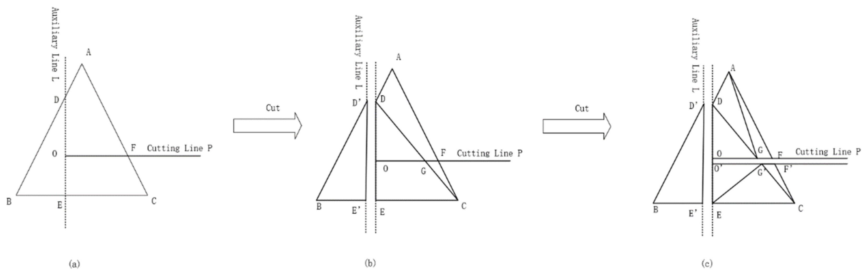
2.2.3. Triangle Cutting

The so-called cutting involves cutting the smallest geometric element and ensuring that the minimum geometric element after cutting still meets the overall geometric characteristics. The oblique photography data model in this paper were composed of triangular patches, so the minimum unit of the model after cutting should still be triangular patches so that the topological relationship between triangular patches can be maintained [34]. In this study, the feature line was used as the cutting line to cut the triangle in the projection plane. Based on the analysis, we divided the intersection mode of the triangle patch and the cutting line into two categories according to whether the vertex of the cutting line was in the triangle or not, and adopted different cutting methods for different intersection modes.
In the cases where there was no cutting line vertex in the triangle, it was divided into two cases: an intersection with two edges of the triangle and an intersection with one edge. If the cutting line intersected with two edges of the triangle, the intersecting part should be trimmed as follows. As shown in Figure 7, the intersection points of the cutting line P and the edges AB and AC of △ABC were calculated as points E and F, respectively, connecting the line segments CE and FE. The line segment CE divided the quadrilateral BCFE generated by cutting into △BCE and △CFE. In this way, the quadrilateral BCFE generated by cutting △ABC using the cutting polygon was cut into two triangles, as shown in Figure 7b. The geometric properties of the triangular patches were maintained, and the topological relationships among the triangular patches were established.
When the cutting line passed through the vertex of a triangle and intersected with an edge of the triangle, the intersecting part was clipped as follows. As shown in Figure 8, it was calculated that the intersection of the cutting line P and the edge ab of △ABC was point E, connecting the line segment CE. Line CE divided △ABC into two triangles: △BCE and △AE′C′, as shown in Figure 8b. The geometric properties of the triangular patches were maintained, and the topological relationships among the triangular patches were established.
In the cases where the vertex of the cutting line did not exist in the triangle, in order to ensure the accuracy of cutting, we used the above method to cut the triangle perpendicular to the cutting line and through the straight line of the vertex, and then used the cutting line to cut the triangle on one side of the cutting line for a second time. As shown in Figure 9, we first made the auxiliary line L perpendicular to the cutting line P through the vertex O, and then calculated that the intersection points of the auxiliary line L and the edges AB and BC of △ABC were point D and point E, respectively, connecting the line segments DE and CD. The line segment CD divided the quadrilateral ADEC generated by cutting into △ADC and △DEC, as shown in Figure 9b. Then, we used the cutting line P to cut △ADC and △DEC, as shown in Figure 9c. The geometric properties of the triangular patches were maintained, and the topological relationships among the triangular patches were established.

2.2.4. Three-Dimensional Model Reconstruction

The reason for reconstructing a 3D model is that the number of vertices and triangular patches in the overall 3D model will be increased by cutting triangular patches. Therefore, it is necessary to reorganize the data in the 3D model.
The reconstruction of a 3D model must return the 2D triangulation on the projection surface to 3D space, which only requires modification of the 3D coordinates. In our analysis, the original vertex was fitted into two planes according to the classification results in Section 2.2.2, and the new vertex was fitted to the manually selected feature line to complete the model reconstruction. The effect is shown in Figure 10.
The oblique photography 3D model requires a real texture map to enhance the realistic effect of the 3D model; thus, it also requires the texture coordinates corresponding to the new vertices. In this study, the texture coordinates of the new vertices were calculated by linear interpolation. The formula is as follows:
u J D = u p 1 + u p 2 u p 1 × d / D v J D = v p 1 + v p 2 v p 1 × d / D
where u J D and v J D are the texture coordinates of the new vertex, u p 1 and v p 1 , respectively; u p 2 and v p 2 are the texture coordinates corresponding to the vertex p 1 p 2 of the edge where the intersection is located; d is the distance from the intersection to the vertex p 1 ; and D is the edge length of the edge.

3. Experimental Results and Discussion

To verify the effectiveness of the proposed method, we used C/C++, OpenSceneGraph (OSG), and a point cloud library (PCL) to carry out the experiments. The original oblique photography data had a large number of building models, and a certain building model was selected in this study for the experiment.
The edge line of the selected building was restored to verify the effect of the edge line restoration method proposed in this paper. As shown in Figure 11, the comparison before and after restoration can realize the edge line restoration of the original model without pretreatment of the model, which has a good restoration effect, highlights the characteristics of the building edge line, and shows a better visual effect.
Compared with the method mentioned in the introduction of this paper [25], for the test data with a range of only 500 m × 500 m, it took 5–6 min to select a specific building and extract its edge feature line. The calculation time will be extended for a larger range of city-level aerial photos. This method adopted interactive feature line drawing, which can improve the rendering effect and operation efficiency of the existing amount of data, and is also the most cost-effective method. It can avoid excessive operation and performance consumption when extracting edge feature lines or possible errors, and can avoid the self-intersection problems of direct straightening and flattening of continuous triangulation. This method improved the operation efficiency while ensuring the same restoration effect.
Compared with the simplex method of triangulation [26], for the test data with a photographing range of 500 m × 500 m, on the premise of the interactive drawing of feature lines, a comparison between the time consumption and memory occupation of the two methods is shown in Table 1. This method was able to reduce the time cost and performance consumption of continuous triangulation topology reconstruction by two to three times; it improved the calculation speed and reduced the time required for restoration. According to the comparison between before and after the restoration of the building edge area, this method used the projection first, and then used the triangular patch cutting algorithm to restore the model, which was simple to operate, had low requirements for computer performance, and effectively improved the operation efficiency on the premise of ensuring the rendering effect.

4. Conclusions

The edge line is the most characteristic area in a building model. The restoration of the edge line of a building model is one of the main problems to be solved in the application of the urban real scene oblique photography 3D building model technology. In order to solve this problem, we used AABB collision detection to detect the triangles around the feature line and project them to cut and reconstruct the continuous triangulation network so as to ensure the flatness of the cutting edge and improve the accuracy of triangle cutting, as well as to avoid the problem of the self-intersection of triangles caused by direct straightening and flattening. The 3D data of the 3D building model were modified and combined with the characteristics of the OSGB data format. The restoring effect was integrated into the original LOD data files at all levels to ensure a smooth browsing effect. The experimental results showed that the proposed method can effectively improve the accuracy and rendering effect of the UAV 3D model.

Author Contributions

Conceptualization, D.C., K.Q., Y.L. and B.M.; Formal analysis, K.H., K.Q., Y.L. and Q.L.; Investigation, K.H., K.Q. and Q.L.; Methodology, D.C., K.H., K.Q. and Y.L.; Project administration, D.C. and B.M.; Resources, D.C. and B.M.; Software, K.H., K.Q., Y.L. and Q.L.; Supervision, D.C. and B.M.; Writing—original draft, K.H., K.Q. and Q.L.; Writing—review and editing, D.C. and B.M. All authors have read and agreed to the published version of the manuscript.

Funding

This research was conducted with support from the National Natural Science Foundation of China (41871310) and the Fundamental Research Funds for the Central Universities (N2124005, N2001020).

Institutional Review Board Statement

Not applicable.

Informed Consent Statement

Not applicable.

Data Availability Statement

The data presented in this study are available upon reasonable request from the corresponding author.

Conflicts of Interest

The authors declare no conflict of interest.

References

  1. Li, D.R.; Shao, Z.F.; Yang, X.M. Theory and Practice from Digital City to Smart City. Geospat. Inf. 2011, 9, 2. [Google Scholar]
  2. Song, Y.S. Cultural Assets Reconstruction Using Efficient 3D-Positioning Method for Tourism Geographic Information System. J. Tour. Leis. Res. 2010, 22, 97–111. [Google Scholar]
  3. Leng, X.; Liu, D.; Luo, J.; Mei, Z. Research on a 3D Geological Disaster Monitoring Platform Based on Rest Service. ISPRS Int. J. Geo-Inf. 2018, 7, 226–244. [Google Scholar] [CrossRef] [Green Version]
  4. Singla, J.G.; Padia, K. A Novel Approach for Generation and Visualization of Virtual 3D City Model Using Open Source Libraries. J. Indian Soc. Remote Sens. 2020, 52, 1239–1244. [Google Scholar] [CrossRef]
  5. Mademlis, I.; Mygdalis, V.; Nikolaidis, N.; Montagnuolo, M.; Negro, F.; Messina, A.; Pitas, I. High-Level Multiple-UAV Cinematography Tools for Covering Outdoor Events. IEEE Trans. Broadcast. 2019, 65, 627–635. [Google Scholar] [CrossRef]
  6. Zhang, Z.X.; Zhang, J.Q. Solutions and Core Techniques of City Modeling. World Sci. Technol. R D 2003, 25, 23–29. [Google Scholar]
  7. Lin, M.; Li, F.Y.; Zhou, H. A Research on the Combination of Oblique Photography and Mobile Applications Based on the Sustainable Development of Tourism. Sustainability 2020, 12, 3501. [Google Scholar] [CrossRef]
  8. Zhang, R.; Li, H.; Duan, K.F.; You, S.C.; Liu, K.; Wang, F.T.; Hu, Y. Automatic Detection of Earthquake-Damaged Buildings by Integrating UAV Oblique Photography and Infrared Thermal Imaging. Remote Sens. 2020, 12, 2621–2649. [Google Scholar] [CrossRef]
  9. Verhoeven, G. Taking Computer Vision Aloft-Archaeological Three-Dimensional Reconstructions from Aerial Photographs with Photo scan. Archaeol. Prospect. 2011, 18, 67–73. [Google Scholar] [CrossRef]
  10. Zhou, X.M.; Meng, X.L.; Zhang, X.P.; MI, Y.H. A method for urban real 3D model building based on oblique photogrammetry. Sci. Surv. Mapp. 2016, 41, 159–163. [Google Scholar]
  11. Jung, J.; Jwa, Y.; Sohn, G. Implicit Regularization for Reconstructing 3D Building Rooftop Models Using Airborne LiDAR Data. Sensors 2017, 17, 621. [Google Scholar] [CrossRef] [Green Version]
  12. Liu, Z.L.; Chen, S.; Chen, P.X. The study and practice on data quality inspection method of city real 3D model based on oblique photography. Bull. Surv. Mapp. 2019, 2, 108–112. [Google Scholar]
  13. Dorninger, P.; Pfeifer, N. A Comprehensive Automated 3D Approach for Building Extraction, Reconstruction, and Regularization from Airborne Laser Scanning Point Clouds. Sensors 2008, 8, 7323–7343. [Google Scholar] [CrossRef] [Green Version]
  14. Xie, L.F.; Zhu, Q.; Hu, H.; Wu, B.; Li, Y.; Zhang, Y.T.; Zhong, R.F. Hierarchical Regularization of Building Boundaries in Noisy Aerial Laser Scanning and Photogrammetric Point Clouds. Remote Sens. 2019, 10, 1996. [Google Scholar] [CrossRef] [Green Version]
  15. Phan, T. A triangle mesh-based corner detection algorithm for catadioptric images. Imaging Sci. J. 2017, 5, 220–230. [Google Scholar] [CrossRef]
  16. Zhou, W.; Peng, R.; Dong, J.; Wang, T. Automated extraction of 3D vector topographic feature line from terrain point cloud. Geocarto Int. 2017, 26, 1036–1047. [Google Scholar] [CrossRef]
  17. Zhao, J.B.; Liu, W.J.; Xia, R.B. An method of feature line extraction of triangle mesh surface model. In Proceedings of the IEEE International Conference on Information and Automation, Shenyang, China, 6–8 June 2012. [Google Scholar]
  18. Lawonn, K.; Trostmann, E.; Preim, B.; Hildebrandt, K. Visualization and Extraction of Carvings for Heritage Conservation. IEEE Trans. Vis. Comput. Graph. 2017, 23, 801–810. [Google Scholar] [CrossRef] [Green Version]
  19. Liu, H.; Dai, N.; Zhong, B.; Li, T.; Wang, J. Extract feature curves on noisy triangular meshes. Graph. Models 2017, 93, 1–13. [Google Scholar] [CrossRef]
  20. Hu, S.M.; Yang, Y.L.; Lai, Y.K. Research Progress of Digital Geometry Processing. Chin. J. Comput. 2009, 32, 1451–1469. [Google Scholar]
  21. Ohtake, Y.; Belyaev, A.; Seidel, H. Ridge-valley lines on meshes via implicit surface fitting. In Proceedings of the ACM Transactions on Graphics, Grenoble, France, 27–29 August 2004. [Google Scholar]
  22. Tsuchie, S.; Higashi, M. Extraction of Surface-feature Lines on Meshes Using Normal Tensor Framework. Comput. Aided Des. Appl. 2014, 2, 172–181. [Google Scholar] [CrossRef]
  23. Rother, C.; Kolmogorov, V.; Blake, A. “Grab-Cut”: Interactive Foreground Extraction Using Iterated Graph Cuts. In Proceedings of the ACM Transactions on Graphics, Grenoble, France, 27–29 August 2004. [Google Scholar]
  24. Lv, C.; Wu, Z.; Wang, X.; Zhou, M.; Toh, K. Nasal Similarity Measure of 3d Faces Based on Curve Shape Space. Pattern Recognit. 2019, 88, 458–469. [Google Scholar] [CrossRef]
  25. Shang, Q.S. Feature Line Constrained Edge Restoration of Oblique Photogrammetric 3D Models. Master’s Thesis, Southwest Jiaotong University, Chengdu, China, May 2019. [Google Scholar]
  26. Wang, Y.; Hao, X.Y.; Li, Y. Study of method for achieving 3D model to be single based on oblique photogrammetry image. Comput. Eng. Appl. 2018, 54, 178–183. [Google Scholar]
  27. Zhang, H.X.; Li, H.; Li, J.H.; Zhao, F. Simplification of tilt photogrammetry 3D model and service release. Bull. Surv. Mapp. 2021, 67, 79–82. [Google Scholar]
  28. Aubel, A.; Boulic, R.; Thalmann, D. Real-time display of virtual humans: Levels of details and impostors. IEEE Trans. Circuits Syst. Video Technol. 2000, 10, 207–217. [Google Scholar] [CrossRef] [Green Version]
  29. Zhang, J.F. Research on the Key Algorithm of 3D Real-Time Dynamic Multisolution Display of Large-Scale Terrain. Ph.D. Thesis, Wuhan University, Wuhan, China, May 2011. [Google Scholar]
  30. Biljecki, F.; Ledoux, H.; Stoter, J. An improved LOD specification for 3D building models. Comput. Environ. Urban Syst. 2016, 59, 25–37. [Google Scholar] [CrossRef]
  31. Bai, L.F.; Chang, C.W.; Wang, Y.T. Intersect Test Algorithm of Oriented Bounding Box Based on Effective Constraint. J. Comput. Aided Des. Comput. Graph. 2016, 28, 1757–1766. [Google Scholar]
  32. Sun, J.G.; Wu, S.H. Collision detection algorithm based on ellipsoid bounding box and spatial decomposition. Comput. Eng. Appl. 2016, 52, 217–222. [Google Scholar]
  33. Hu, X.; Huang, M.; Zhou, H.X. Automated extracting highway from mobile laser scanning point clouds. Sci. Surv. Mapp. 2019, 44, 101–106. [Google Scholar]
  34. Wen, P.Z.; Lei, Y.Q.; Sun, M.L. Defective hole identification and hole-filling for 3D reconstruction mesh models. Appl. Res. Comput. 2020, 37, 1234–1238. [Google Scholar]
Figure 1. Flow chart of edge line restoration.
Applsci 12 12911 g001
Figure 2. Schematic diagram of cylinder selection range.
Applsci 12 12911 g002
Figure 3. Local triangle vector graph.
Applsci 12 12911 g003
Figure 4. Distribution of triangle normal vectors in three-dimensional space. Normal vectors in the red circles are the centralized distribution, and normal vectors in the blue circle are discrete distribution.
Applsci 12 12911 g004
Figure 5. Fitting plane rendering of normal vectors in two main directions after removing discrete normal vectors. The yellow and blue planes are fitting planes of the main normal vectors, the white plane is the fitting plane of the discrete normal vectors.
Applsci 12 12911 g005
Figure 6. Diagram of the effect of local triangle projection on the projection plane. Green line is the feature line of the edge line, and the white lines are TINs of the building model.
Applsci 12 12911 g006
Figure 7. Triangle clipping method 1. (a) Triangle before cutting and (b) triangle after cutting.
Applsci 12 12911 g007
Figure 8. Triangle clipping method 2. (a) Triangle before cutting and (b) triangle after cutting.
Applsci 12 12911 g008
Figure 9. Triangle clipping method 3. (a) Triangle before cutting. (b) Triangle cut by an auxiliary line. (c) Triangle cut by an auxiliary line and a cutting line.
Applsci 12 12911 g009
Figure 10. Rendering of local triangulation after edge line restoration. Green line is the edge line of the building model, and the white lines are TINs of the building model.
Applsci 12 12911 g010
Figure 11. Comparative diagram of before and after edge restoration.
Applsci 12 12911 g011
Table 1. Comparison of the two methods for test data of 500 m × 500 m.
Main Parameters of Computer PerformanceSimplex Method of TriangulationMethod in This Paper
Computer CPUINTEL CORE I7-12700HINTEL CORE I7-12700H
Computer memory16 GB16 GB
GPUNvidia RTX 3060tiNvidia RTX 3060ti
Time consumption10 min3.5 min
Memory consumption53%28%
Publisher’s Note: MDPI stays neutral with regard to jurisdictional claims in published maps and institutional affiliations.

