Article

A Multi-Segment Expanded Anchor for Landslide Emergency Management

1
Institute of Exploration Technology, Chinese Academy of Geological Sciences, No. 139 Ganghua Road, Pidu District, Chengdu 611734, China
2
Chengdu Huajian Geological Engineering Technology, Co., Ltd., No. 135 Ganghua Road, Pidu District, Chengdu 611734, China
*
Author to whom correspondence should be addressed.
Appl. Sci. 2022, 12(24), 12985; https://doi.org/10.3390/app122412985
Submission received: 2 December 2022 / Revised: 14 December 2022 / Accepted: 15 December 2022 / Published: 17 December 2022
(This article belongs to the Section Civil Engineering)

Abstract

:
Conventional mortar cemented anchors cannot meet the needs for landslide emergency management, as they can withstand loads only after mortar curing for 14–28 days. This study developed a multi-segment expanded anchor (MSEA) that expands using a sliding mechanism and rapidly bears loads using multiple load-bearing bodies by the frictional drag along the perforated wall, and the reaction force of the underreams’ platforms. Field tensile tests without grouting and the secondary tensile tests of six MSEAs, each with a length of 23 m, were carried out. The field tests show that the installed load-bearing bodies expanded steadily when the MSEAs were tensioned without grouting. In hard sandstones, the initial tensile force of each load-bearing body exceeded its design value of 150 kN, and the initial bearing capacity of each MSEA was greater than 300 kN, which exceeded the bearing capacity of the existing anchors regardless of grouting. The secondary tensile tests of the MSEAs were conducted after they were grouted for three days, and their lock-off load was greater than their design value of 600 kN. Based on the elastic mechanics and the stress process of the MSEAs, this study derived the theoretical equations of the ultimate bearing capacity of the MSEAs without grouting. The results calculated using the theoretical equations were roughly consistent with the field test results of the ultimate bearing capacity.

1. Introduction

The concealment and emergency of landslides tend to cause great losses of human life and production, which can be minimized by rapid and effective emergency response. As an important part of landslide emergency response, emergency management plays an instrumental role before or after landslides. However, a gap still exists between the actual control effects and the satisfactory and optimal solutions due to limited technical conditions. For example, a large-scale landslide occurred in Baige Village, Jiangda County, Changdu City, on 11 October 2018. Emergency investigation and monitoring [1] were implemented, but emergency management could not be conducted due to the limited technical and construction conditions. After 23 days, a high-altitude rock mass of about 215 × 104 m3 at the rear edge of the landslide collapsed and slid again, causing a disaster for 102,000 people, and the collapse of more than 3400 houses in Tibet, Sichuan, and Yunnan. Moreover, the landslide in Baige Village is still facing the risk of recurring and blocking the Jinsha River [2,3]. Therefore, it is a challenge for geologists to take effective measures and provide decision-makers with new tools for landslide emergency management.
As an effective means of active support, lattice anchors are widely used in the emergency management of severe landslides. Conventional anchors support loads using grouted bodies [4,5,6]. Fully grouted anchors are affected by anchor factors, grouting-related factors, stresses, anchor installation, and rock-mass conditions [7]. However, both the grouted bodies and the concrete lattice girders require a long curing time. Therefore, conventional anchors cannot fully meet the needs of landslide emergency management. For instance, 284 anchors were constructed for emergency reinforcement against the landslide in Danba County, Ganzi Tibetan Autonomous Prefecture, Sichuan Province, in early February 2005; however, the first anchor was not tensioned for about one month and the whole anchoring project was completed in June, missing the scope of emergency rescue date [8,9]. In 2019, a landslide in the Jiulao section of the Gedan Highway was reinforced using sloping and fully grouted anchors. The landslide mass was greatly deformed again before anchor tensioning within a 7-day grouting curing. Consequently, the anchors were tensioned with a U-steel reaction support [10].
Many studies have been conducted to reduce the construction period of anchorages. To facilitate the rapid construction of lattice girders, precast concrete lattices and steel anchor piers can be used to improve construction efficiency and environmental friendliness [11,12,13]. One method for achieving the rapid load bearing of anchors is to reduce the time difference between the initial and final setting of mortar. For instance, the time difference of self-expanding anchors can be reduced by 78% by using expanding cement grout [14,15]. The other method to achieve rapid load bearing with anchors is to adopt special structures to improve the initial bearing capacity. For example, many new anchors have gradually emerged in recent decades, such as mechanically underreamed anchors [16], self-burying anchors [17], earth anchors with squibbing [18], under-reamed ground anchors with capsules [19,20,21], umbrella-shaped anchors [22], and high-pressure jet grouting (HPJG) anchors [23]. However, some of these anchors have insufficient tonnages, and others still rely on mortar strength, resulting in a lengthy construction period. For instance, mechanically underreamed anchors have a pullout resistance of 250 kN, are based on grouted bodies, and are suitable for soft soil; self-expanding anchors have a pullout resistance of about 116 kN and can be used for rocks; umbrella-shaped anchors have a tensile resistance of 100 kN, and HPJG anchors are based on grouted bodies. Therefore, these new anchors cannot meet the emergency management requirements for severe rockslides.
In this study, a MSEA with a sliding mechanism was proposed. The MSEA can be prestressed to 300 kN without grouting, surpassing the bearing capacity of existing anchors regardless of grouting. Moreover, the construction period of the MSEA was greatly reduced from 14–28 days to about one day. Based on field tests and theoretical analysis, this study illustrated the operating mechanisms of the MSEA and derived the equations of its ultimate bearing capacity.

2. MSEA Structure

A MSEA is a prestressed anchor with a sliding mechanism. Expanded through a sliding anchorage, the MSEA can rapidly support loads with the frictional drag along the hole wall and the reaction force from the underreams’ platforms. Figure 1 shows a schematic diagram of the MSEA structure. The core component of a MSEA is the slidable and expandable load-bearing body, which is mainly composed of a guide head, slide grooves, a slide anchorage, and several bearing blades. Among them, the sliding anchorage is equipped with an anchor with a P-type anchorage.
Figure 1a shows the initial state of a MSEA. Specifically, a MSEA is installed to the design depth using a towing wheel at the hole bottom, when the bearing blades are closed. Figure 1b shows the lock-off state after initial tension. When the MSEA undergoes an initial tension, the towing wheel can provide a reaction force of approximately 50 kN. The sliding anchorage then drives the bearing blades to expand, causing the blades to press and rub against the hole wall. As a result, the rapid bearing of the MSEA can be achieved through this frictional drag and the reaction force of the underreams’ platforms. To improve the initial bearing capacity of the MSEA, segmental underreaming and multiple load-bearing bodies are adopted to share the stress. A MSEA becomes a permanent anchor after being locked off through initial tension, grouting, and secondary tension.

3. Field Tests

3.1. Overview

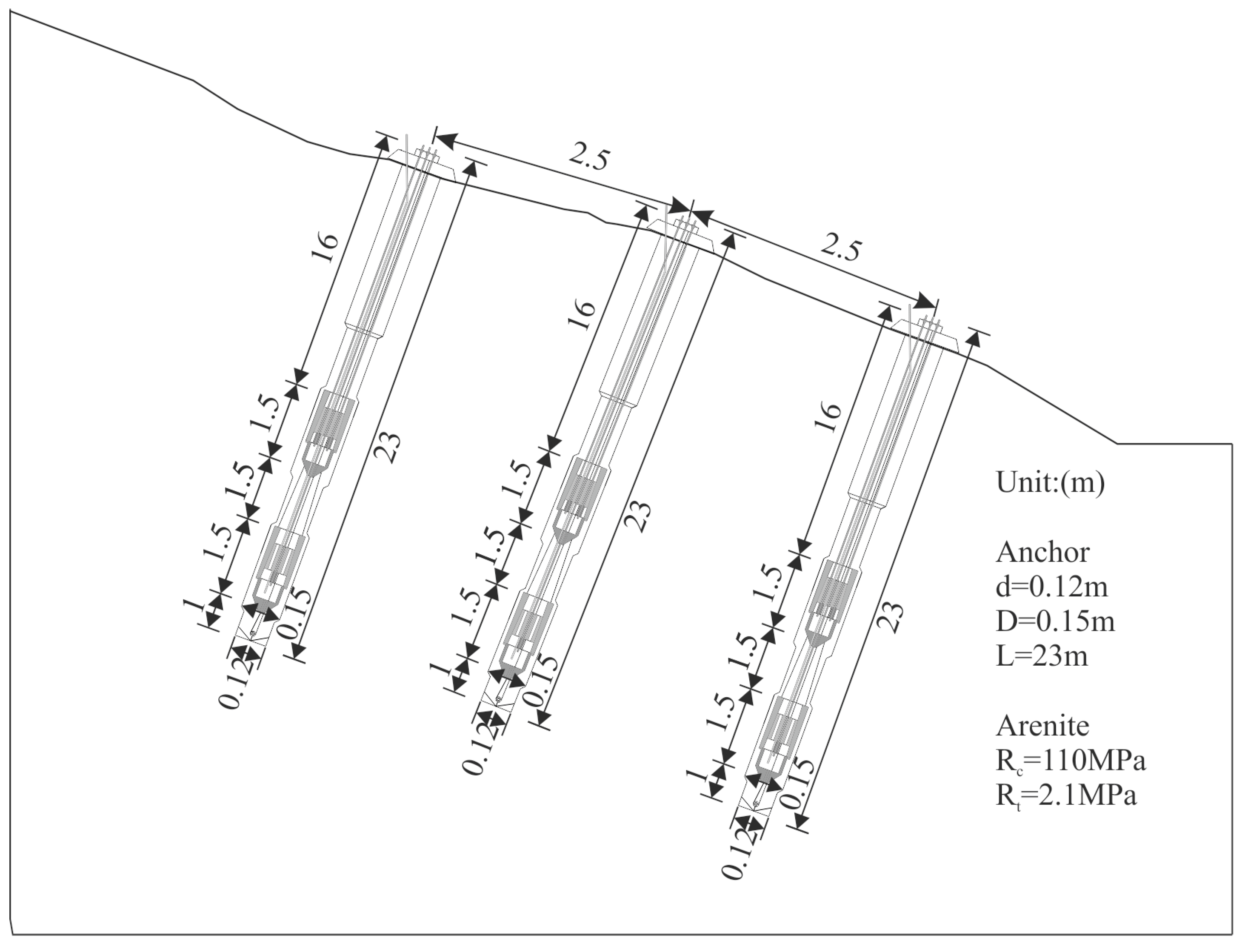
As shown in Figure 2, the field tests of MSEAs were carried out at the Beichuan test base, Mianyang City, Sichuan Province, with geographical coordinates of 104°35′46.67″ E and 31°51′31.42″ N. There exists a smooth interface with a slope of approximately 25° left after a landslide on the test site. The exposed bedrock is a relatively intact hard, greyish-black arenites of Devonian D2–3 Geotechnical test results show that the arenites have a density of 2.2 g/cm3, compressive strength of 110 MPa, and a tensile strength of 2.1 MPa.
Six MSEAs in three rows and two columns were tested in the field, each with a length of 23 m. The formed hole with a diameter (d) of 120 mm was enlarged using a concentric expansion drill, achieving a final diameter (D) of 150 mm and a length of each underream of 1.5 m. Each MSEA has two load-bearing bodies, with a total design anchoring force of 600 kN. The design value of the initial bearing capacity of each MSEA without grouting was 300 kN (150 kN for each load-bearing body).

3.2. Test Method

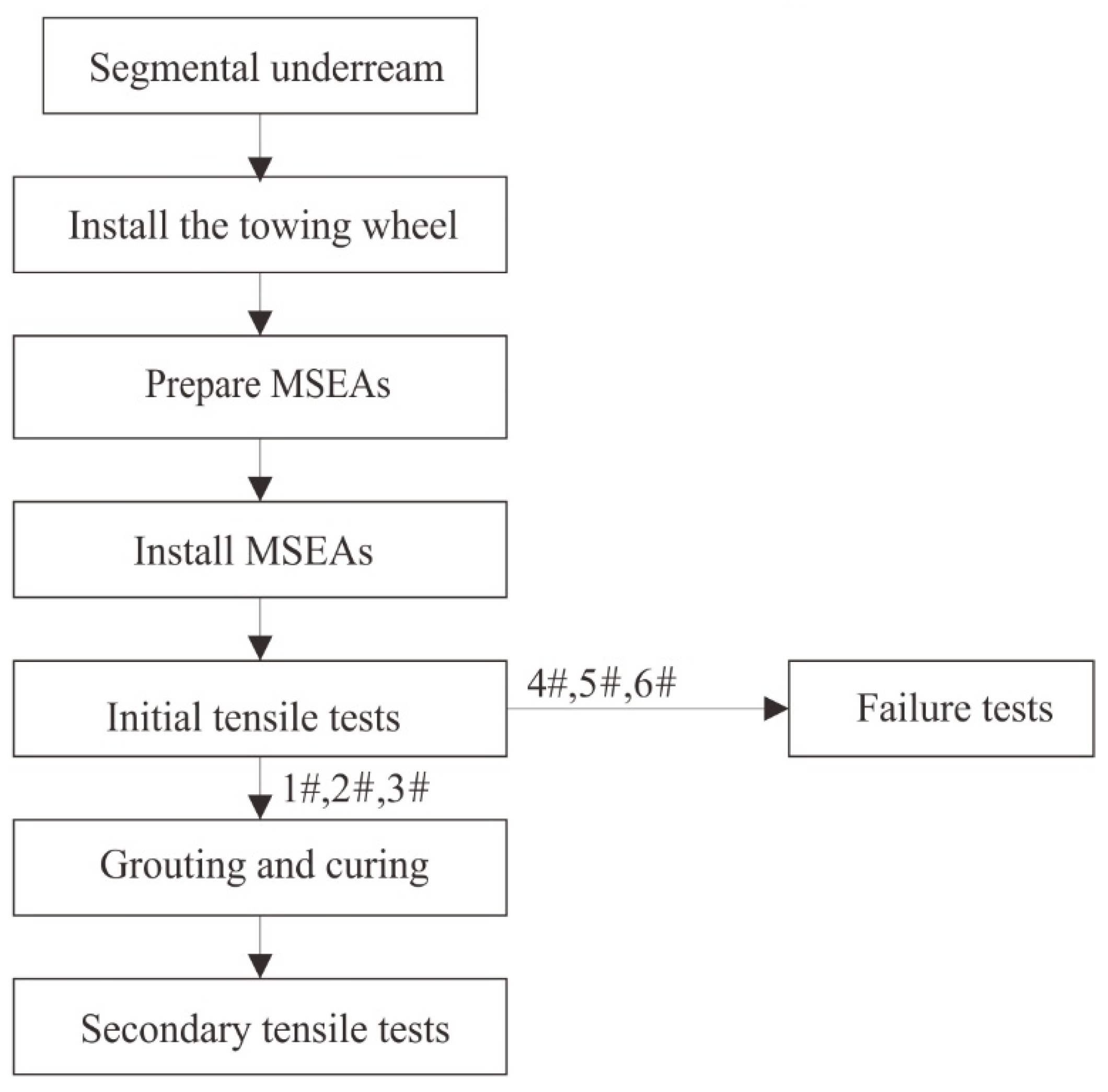
As shown in Figure 3, the test procedure mainly included segmental underreaming, installing the towing wheel, preparing MSEAs, installing MSEAs, conducting initial tensile tests (failure tests for partial MSEAs), grouting, and curing, and conducting secondary tensile tests.
(1)
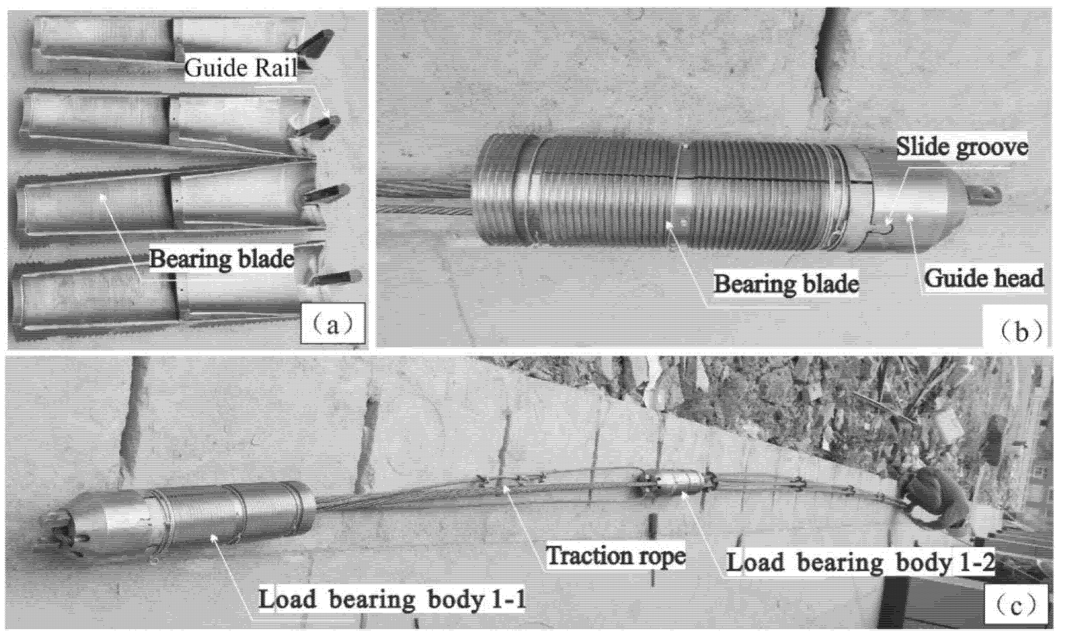
Preparing MSEAs. Figure 4 illustrates the assembly process of a MSEA during the field tests. The bearing blades are depicted in Figure 4a. Each load-bearing body is composed of four bearing blades, each of which has a guide rail at the end. An assembled load-bearing body is shown in Figure 4b. First, the anchor with a P-type anchorage passed through the sliding anchorage, and the guide rails at the ends of the bearing blades were inserted into the sliding groove reserved at the guide head. Then, the sliding anchorage was wrapped and surrounded by the blades. The surfaces of the blades were serrated to increase the frictional drag between the bearing blades and the perforated wall. Figure 4c shows a photo of a MSEA with a length of 23 m, that used two load-bearing bodies to share the pressure. To facilitate the installation of the MSEAs, a traction rope was used to pass through the load-bearing bodies.
(2)
Initial tensile tests. To determine the initial bearing capacity of the MSEAs without grouting, six MSEAs each with a length of 23 m were tested in the field without grouting.
(3)
Failure tests without grouting. The failure tests without grouting were conducted for MSEAs Nos. 4–6 to determine their ultimate bearing capacity without grouting. During loading, the two load-bearing bodies of each MSEA were cyclically stressed under the control of oil pressure in order to achieve uniform stress between them. Load-bearing bodies of each MSEA were tensioned successively under an oil pressure of 10 MPa and were then tensioned in sequence under an oil pressure of 12.5 MPa. In this way, a staged cyclic tension was performed.
(4)
Secondary tensile tests: Secondary tensile tests were conducted on MSEAs Nos. 1, 2, and 3 after mortar curing for 14 days, three days, and three days, respectively.

3.3. Analysis of Test Results

Table 1 shows the statistics of the test results. Before grouting, the lock-off load of all MSEAs reached more than 300 kN after the initial tension, and the lock-off load of a single load-bearing body was significantly higher than its design value of 150 kN, meeting the design requirements. MSEAs Nos. 1–3 had a mortar curing time of fourteen days, three days, and three days, respectively. As shown in this table, MSEAs Nos. 1–3 had a maximum tensile force of 852 kN, 865 kN, and 865 kN, respectively. The MSEAs could provide a total design anchoring force of 600 kN within three days.
The MSEA can be prestressed to 300 kN without grouting, surpassing the bearing capacity of existing anchors regardless of grouting. Moreover, the construction period of the MSEA was greatly reduced from 14–28 days to about one day. After being grouted, it can be tensioned again, which makes it a permanent anchor.
Figure 5 shows the tension curves obtained from field tests of the MSEAs. Considering the similarity of these trends, the tension process of MSEA No. 2 was illustrated as an example, as shown in Figure 5b. The curve OA1B1C1D1 represents the tensile process of load-bearing body No. 1 of MSEA No. 2 (also referred to as load-bearing body 2-1). At stage OA1, the bearing blades gradually expanded and the sliding anchorage moved relative to the load-bearing body. The bearing blades were not in contact with the hole wall after gradually expanding, thus the prestress was almost 0. At stage A1B1, friction occurred between the bearing blades and the hole wall, and the tensile force increased to 138 kN. At stage B1C1, the bearing blades slid along the hole wall, and the tensile force dropped instantly to 60.60 kN when it was greater than 138 kN. At stage C1D1, the tensile force increased from 131.8 kN to 172.75 kN, the steel strands had an elastic deformation displacement of 14 mm, and the load-bearing body 2-1 no longer slid as its upper end pressed against the lock at the underream. The curve OA2B2 represents the tension process of the load-bearing body 2-2. At stage OA2, the bearing blades gradually expanded. At stage A2B2, friction occurred between the bearing blades and the hole wall, the tensile force of the load-bearing body increased rapidly to 170 kN, and the total tensile force of the MSEAwas 342.75 kN, meeting the design requirements. Figure 5a–f show that the lock-off load of various MSEAs after the initial tension was greater than the design value of their total bearing capacity without grouting (300 kN), meeting the design requirements. Moreover, the No. 2 load-bearing bodies in MSEAs Nos. 4–6 did not utilize the bearing capacity of the lock at the underream.
Figure 5g–i show the failure test results of MSEAs Nos. 4–6 without grouting. As shown in Figure 5g, load-bearing body 4-2 failed when the oil pressure reached 30 MPa, with a load of approximately 226 kN; the load-bearing body 4-1 failed when the oil pressure reached 47.5 MPa, with an ultimate load of approximately 480 kN. As shown in Figure 5h, load-bearing body 5-2 failed first at a load of approximately 329 kN, and then load-bearing body 5-1 failed at an ultimate load of approximately 470 kN. As shown in Figure 5i, load-bearing body 6-2 failed first at a load of approximately 227 kN, and then load-bearing body 6-1 failed at an ultimate load of approximately 419 kN. These results suggest that, load-bearing body No. 2, which did not utilize the platform to bear pressure, always failed prior to load-bearing body No. 1 in all the MSEAs.

4. Calculation Method of the Ultimate Bearing Capacity of MSEAs

As shown in previous test studies, the bearing capacity of an expanded anchor is related to soil strength, hole diameter, underreaming types, and failure mode [24,25]. The typical methods for exploring the estimation equation for the tensile resistance of an expanded-base pile mainly include the friction cylinder method, the Meyerhof-Adams method [26], and the ultimate upward tensile resistance algorithm [27]. However, these methods are not applicable to MSEAs.

4.1. Initial Tension Process

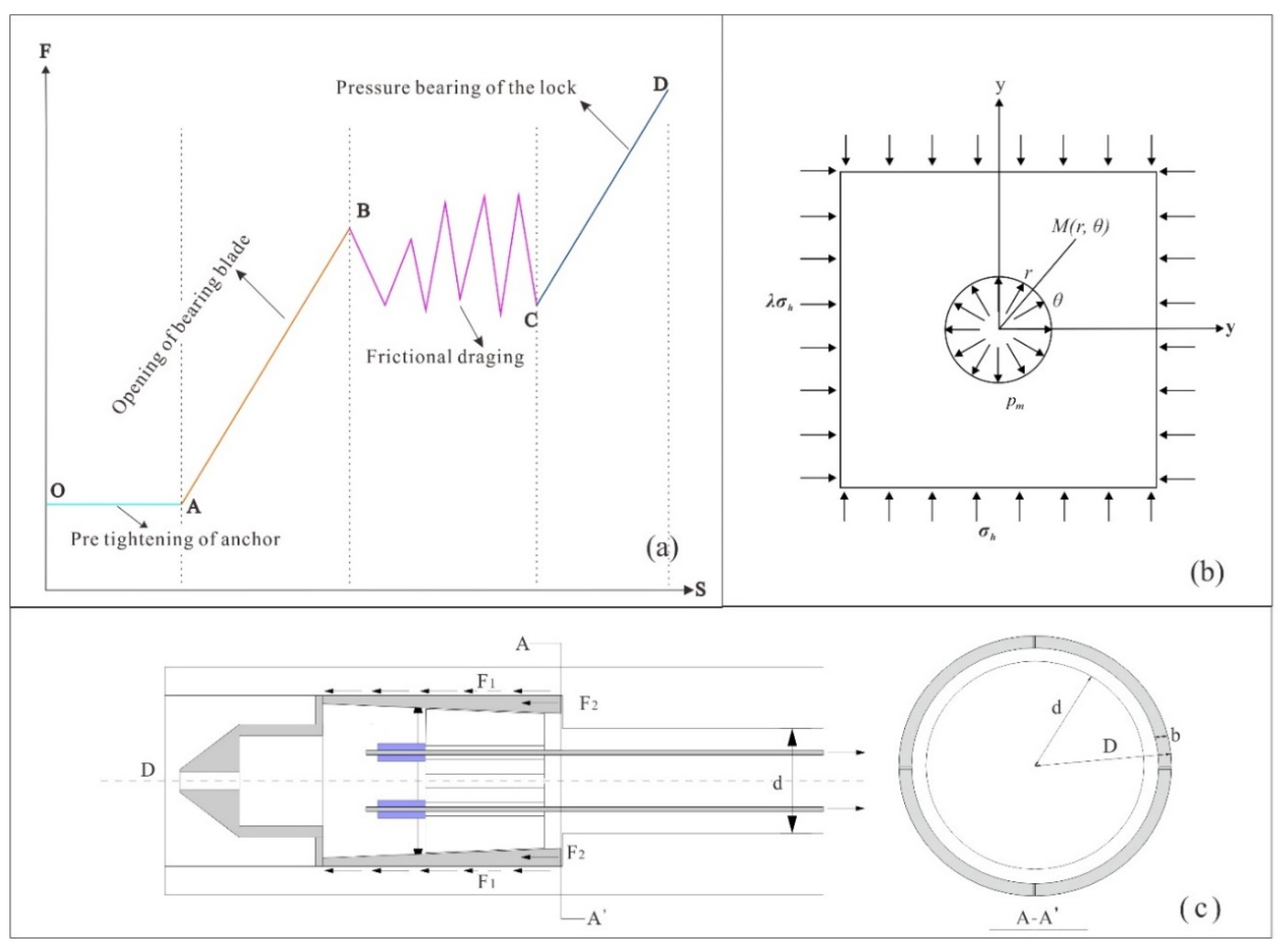
A MSEA underwent a four-stage stress process according to the initial tensile tests, as shown in Figure 6a.
(1)
Stage OA: The steel strands experienced pre-tension. The sliding anchorage moved relative to the load-bearing body. The bearing blades gradually expanded but were not in contact with the hole wall.
(2)
Stage AB: The bearing blades gradually expanded and pressed against the hole wall, causing friction.
(3)
Stage BC: The bearing blades were completely expanded and closely fitted onto the hole wall. The MSEA supported the load only by frictional drag along the hole wall.
(4)
Stage CD: The upper end of the load-bearing body was pressed against the lock in the upper part of the underream. The lock provided a reaction force in addition to the frictional drag between the blades and the hole wall.

4.2. Fundamental Assumptions

The following basic assumptions were made based on the results from the field tests and the stress characteristics of the tension process.
(1)
At stage BC, the tension is decomposed into two superimposed parts, namely the pressure of the bearing blades against the hole wall and the axial tension of the load-bearing bodies.
(2)
At stage BC, the contact pressure between the bearing blades and the hole wall is evenly distributed when the bearing blades expand and press the hole wall.
(3)
At stage BC, the rock masses of the hole wall are in the state of ultimate stress at the moment of slip. In other words, the sliding of the MSEA is caused by the tensile failure of the rock masses and not by the failure of the load-bearing body.
(4)
At stage CD, the upper end of the load-bearing body presses the lock in the upper part of the underream. The lock may generate a reaction force in addition to the frictional drag between the blades and the hole wall.

4.3. Ultimate Bearing Capacity at Stage BC of the MSEAs

The contact pressure between the bearing blades and the hole wall is evenly distributed when the bearing blades press against the hole wall and can be simplified as a plane problem, as shown in Figure 6b. In this figure, σre is the radial normal stress of the rock masses around the hole, σθe is the hoop normal stress, and τrθe is the shear stress; pm is the average contact pressure between the expanded blades and the hole wall; r0 is the radius of the hole wall; r is the polar radius of any point; θ is the polar angle; σh is the horizontal in-situ stress; λ is the ratio of two horizontal in-situ stresses.
The analytical solution of the stress field around the hole was achieved based on elastic mechanics:
σ r e = σ h 2 ( 1 + λ ) 1 r 0 2 r 2 ( 1 λ ) 1 4 r 0 2 r 2 + 3 r 0 4 r 4 cos ( 2 θ ) + p m r 0 2 r 2 σ θ e = σ h 2 ( 1 + λ ) 1 + r 0 2 r 2 + ( 1 λ ) 1 + 3 r 0 4 r 4 cos ( 2 θ ) p m r 0 2 r 2 τ r θ e = σ h 2 ( 1 λ ) 1 + 2 r 0 2 r 2 3 r 0 4 r 4 sin ( 2 θ )
For any point on the hole wall,
r = r 0
For areas with mild tectonic activities, the horizontal initial in-situ stress can be taken as half of the gravity stress:
σ h = 0.5 σ z , λ = 1
where σz is the gravity stress.
Substituting (1) and (2) into (3) yields:
σ r e = p m σ θ e = 2 σ h p m τ r θ e = 0
When the rock masses of the hole wall are in the ultimate state:
σ θ e = 2 σ h p m b = R t
where Rt is the tensile strength of rocks, and pmb is the contact pressure between the bearing blades and the hole wall when the rock masses are in their ultimate stress state.
Then, the frictional drag between the hole wall and the bearing blades is:
F 1 = μ π D l p m b
where F1 is the frictional drag between the hole wall and the bearing blades; μ is the friction coefficient between the hole wall and the bearing blades; D is the hole diameter of the underream; l is the length of the part with applied load.

4.4. Ultimate Bearing Capacity at Stage CD of the MSEAs

When the upper part of the load-bearing body presses the lock at the upper end of the underream, the lock of the underream could also provide a reaction force in addition to the frictional drag between the blades and the hole wall, as shown in Figure 6c.
In this case, the bearing capacity is:
F u = F 1 + π × D 2 ( D 2 b ) 2 4 × R c
where Fu is the total bearing capacity, b is the contact width between the upper end of the load-bearing body and the lock of the underream, and Rc is the compressive strength of rocks.

4.5. Verification

During field tests, the formed holes of the MSEAs had a diameter of 120 mm; they were expanded to a diameter of 150 mm. Moreover, the bearing blades had a length of 450 mm, a burial depth of 20 m, and an assumed friction coefficient of 0.4. The test results of rock samples showed that the arenites had a density of 2.2 g/cm3, a compressive strength of 110 MPa, and tensile strength of 2.1 MPa. According to Equations (5) and (6), the frictional drag between the hole wall and the bearing blades was 215 kN, which was close to the measured ultimate load of the No. 2 load-bearing body of each MSEA (only relying on the frictional drag along the hole wall) and indicating relatively safety.
The contact width between the upper part of the load-bearing body and the lock of the underream was set at 5 mm. According to Equation (7), a single load-bearing body had a bearing capacity of approximately 465 kN, which was close to the measured ultimate load capacity of the No. 1 load-bearing body of each MSEA (combined effects of the frictional drag along the hole wall and the reaction force at the lock). The equations for the ultimate bearing capacity of the MSEAs indicate that the strength of the rock masses is the key factor affecting the bearing capacity. For a given case, the design value of the initial tensile force and the strength of the rock masses can be used to select the hole-forming process and determine the need for underreaming and the number of underreams.

5. Conclusions

This study successfully developed a MSEA with a total design anchoring force of 600 kN. The MSEA can be tensioned without grouting, and has an initial bearing capacity of up to 300 kN, which exceeds the bearing capacity of existing anchors regardless of grouting. After being grouted, the MSEAs could provide a total design anchoring force of 600 kN within three days. Therefore, the MSEA can greatly reduce the construction period from 14–28 days to three days. The initial tension tests of the MSEAs show that the stress process of the MSEAs can be divided into four stages, namely the pre-tightening of steel strands, the opening of bearing blades, the frictional dragging along the hole wall, and the pressure bearing at the lock The secondary tension tests of the MSEAs show that all the MSEAs have lock-off load greater than the design value of 600 kN. This study derived the calculation equations of the initial bearing capacity of the MSEAs based on their initial tension process and elastic mechanics. The calculation results of the MSEAs obtained using the calculation equations approximate to the test results of their ultimate bearing capacity without grouting in hard arenites, a single load-bearing body has an ultimate bearing capacity of approximately 215 kN when only relying on the frictional drag along the hole wall, and has an ultimate bearing capacity of up to 465 kN when relying on both the frictional drag along the hole wall and the reaction force of the platforms of underreams. The equations can provide a theoretical basis for the design of the MSEAs used in landslide emergency management.

Author Contributions

Conceptualization: D.Y. (Dong Yang); methodology: D.Y. (Dong Yang), Q.W. and Z.J.; formal analysis and investigation: D.Y. (Dong Yang) and Q.W.; writing—original draft preparation: D.Y. (Dong Yang); writing—review and editing: D.Y. (Dong Yang); funding acquisition: D.Y. (Dongxu Yang); resources: D.Y. (Dongxu Yang). All authors have read and agreed to the published version of the manuscript.

Funding

This work was supported by the National Natural Science Foundation of China [grant number 41807300] and the Geological Survey Program of China [grant number DD20221745].

Institutional Review Board Statement

Not applicable.

Informed Consent Statement

Not applicable.

Data Availability Statement

Not applicable.

Conflicts of Interest

The authors declare that they have no known competing financial interest or personal relationship that could have appeared to influence the work reported in this paper.

References

  1. Gao, C.; Xu, Q.; Peng, S. Application research of UAV photogrammetry technology in the emergency rescue of Baige landslide. J. Catastrophol. 2020, 35, 203–210. [Google Scholar]
  2. Deng, J.; Gao, Y.; Yu, Z.; Xie, H. Analysis on the formation mechanism and process of Baige landslides damming the upper reach of Jinshan River, China. Adv. Eng. Sci. 2019, 51, 9–16. [Google Scholar]
  3. Feng, W.; Zhang, G.; Bai, H.; Zhou, Y.; Xu, Q.; Zheng, G. A preliminary analysis of the formation mechanism and development tendency of the huge Baige landslide in Jinsha River on October 11, 2018. J. Eng. Geol. 2019, 27, 415–425. [Google Scholar]
  4. Kim, N.-K. Performance of Tension and Compression Anchors in Weathered Soil. J. Geotech. Geoenvironmental Eng. 2003, 129, 1138–1150. [Google Scholar] [CrossRef]
  5. Kim, N.-K.; Park, J.-S.; Kim, S.-K. Numerical simulation of ground anchors. Comput. Geotech. 2007, 34, 498–507. [Google Scholar] [CrossRef]
  6. Li, C.; Stillborg, B. Analytical models for rock bolts. Int. J. Rock Mech. Min. Sci. 1999, 36, 1013–1029. [Google Scholar] [CrossRef]
  7. Kim, H.; Rehman, H.; Ali, W.; Naji, A.M.; Kim, J.-J.; Kim, J.; Yoo, H. Classification of Factors Affecting the Performance of Fully Grouted Rock Bolts with Empirical Classification Systems. Appl. Sci. 2019, 9, 4781. [Google Scholar] [CrossRef] [Green Version]
  8. Yin, Y.; Li, T.Q.; Tang, J. Landslide reactivation and emergency stabilization on Danba county town in Sichuan province. Chin. J. Rock Mech. Eng. 2008, 27, 972–978. [Google Scholar]
  9. Fan, X.M.; Xu, Q.; Huang, R.Q. Dynamical optimal anchoring design and information construction of Danba landslide. Chin. J. Rock Mech. Eng. 2007, 26, 4139–4146. [Google Scholar]
  10. Lin, C.Y.; Pan, X.C. Application of anchorage engineering in landslide emergency rescue. Subgrade Eng. 2019, 2, 235–240. [Google Scholar]
  11. Yang, D.; Wang, Q.C.; Yan, J.F. Two rapid set anchor piers and their application in Phoenix Rock unstable slopes. J. Lanzhou Univ. Nat. Sci. 2015, 51, 847–854. [Google Scholar]
  12. Zhang, Y.; Wang, Q.; Yang, D.; Shi, S. The research and application of 500 kN pre-cast high strength concrete anchorage pier products. J. Eng. Geol. 2015, 23, 793–797. [Google Scholar]
  13. Song, J.; Wang, Q.C.; Cheng, Y.J. The research and application of steel anchorage block in geo-hazard quick anchoring. Sci. Technol. Eng. 2017, 17, 129–133. [Google Scholar]
  14. Liu, J.; Zhang, L.S.; Sun, T. Construction performance and long-term stability of self-expansion anchoring materials. J. Build. Mater. 2019, 22, 656–672. [Google Scholar]
  15. Li, L.J.; Zhou, Y.; Yang, Y.N. Study on the method for determining the limit content of expansion agent in anchor body of self-expanding bolt. Rock Soil Mech. 2010, 41, 3266–3277. [Google Scholar]
  16. Jia, X.Y.; Yue, D.C.; Li, M. Study on construction process of mechanical reamed anchor and its application. Geotech. Investig. Surv. 2017, 4, 18–21. [Google Scholar]
  17. Kerr, N. A self-burying anchor of considerable holding power. In Proceedings of the Annual Offshore Technology Conference, Houston, TX, USA, 3–6 May 1976. [Google Scholar]
  18. Wang, J.J.; Zhao, C.H.; Yao, G.Z. Application of earth anchor with squibbing in landslide control. Chin. J. Geotech. Eng. 1996, 18, 41–46. [Google Scholar]
  19. Zhong, L.; Gang, G.; Zhang, Y. Construction technology and engineering applications of capsule-type under-reamed ground anchor. Chin. J. Geotech. Eng. 2014, 36, 205–211. [Google Scholar]
  20. Liu, Z.; Zhang, C.; Zhang, Y.; Lu, M. Field test study of under-reamed ground anchorage with capsule in Ningbo area. Rock Soil Mech. 2018, 39, 295–301. [Google Scholar]
  21. Gang, G.; Zhong, L.; Li, Y.-K. Model test research on failure mechanism of underreamed ground anchor. Chin. J. Rock Mech. Eng. 2013, 32, 1677–1684. [Google Scholar]
  22. Mei, G.X.; Xu, M.; Song, L.H.; Zhou, F.; Zai, J.M. In-situ tests on new umbrella-shaped anti-float anchors. Chin. J. Geotech. Eng. 2010, 32, 892–896. [Google Scholar]
  23. Zhang, R.-J.; Zheng, J.-J.; Li, P.-Y.; Zhang, J.; Yu, S. A method for predicting mechanical behaviour of HPJG–Anchors–Part I: Mechanical characteristics and load transfer models. Comput. Geotech. 2012, 45, 62–73. [Google Scholar] [CrossRef]
  24. Tistel, J.; Grimstad, G.; Eiksund, G. Testing and modeling of cyclically loaded rock anchors. J. Rock Mech. Geotech. Eng. 2017, 9, 1010–1030. [Google Scholar] [CrossRef]
  25. Wang, T.; Chang, J.; Yin, Z.; Gong, P.; Shi, W.; Li, N. Theory and full-scale simulation testing of the mechanical properties of anchors under a variable lateral pressure coefficient. Arab. J. Geosci. 2021, 14, 136. [Google Scholar] [CrossRef]
  26. Liu, J.L. Pile Engineering Handbook; China Architecture and Building Press: Beijing, China, 1995; ISBN 9787112180721. [Google Scholar]
  27. Liu, W.B.; Zhou, J.; Temuer, M.K. Uplift tests and calculations of under-reamed piles. Ind. Constr. 2003, 33, 42–45. [Google Scholar]
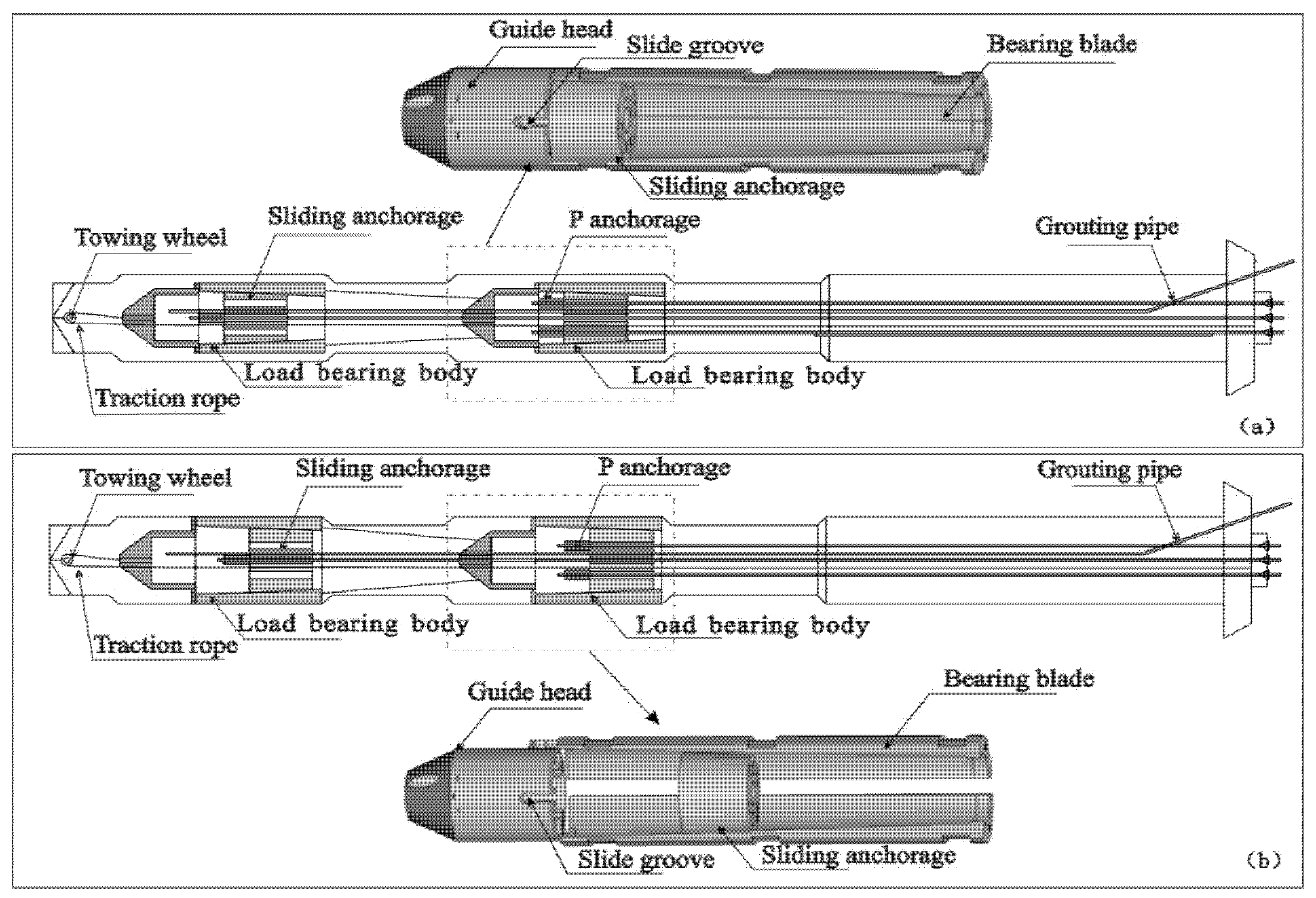
Figure 1. Schematic diagram of the MSEA structure. (a) The initial state; (b) the lock-off state.
Applsci 12 12985 g001
Figure 2. A schematic diagram of field tests.
Applsci 12 12985 g002
Figure 3. Flow chart of the field tests.
Applsci 12 12985 g003
Figure 4. Making of an MSEA. (a) A photo of the bearing blades; (b) a photo of the assembled load-bearing body; and (c) a MSEA with a length of 23 m.
Applsci 12 12985 g004
Figure 5. Tension curves of the MSEAs. (af): The tension processes of MSEAs Nos. 1–6, respectively; (gi): failure test results of MSEAs Nos. 4–6 without grouting, respectively.
Applsci 12 12985 g005
Figure 6. Mechanical diagrams of the MSEAs. (a) The bearing process of the MSEAs without grouting; (b) the mechanical diagram of the bearing blades; and (c) the mechanical diagram of the lock.
Applsci 12 12985 g006
Table 1. Field test results of the MSEAs (kN).
Anchor Cable No.Design Value of a Single Load-Bearing BodyInitial TensionSecondary Tension
Load-Bearing Body No. 1Load-Bearing Body No. 2Total Lock-off LoadDesign Value of
the MSEA
Maximum
Tensile Force
Maximum
Tensile Force
Lock-off LoadMaximum
Tensile Force
Lock-off Load
1150180.7171.3152.8145.0316.3600852
2150172.8163.4172.3162.4324.4600865
3150191.4185.3138.0130.0315.3600865
4150175.6166.5164.0154.9320.9//
5150175.6164.8166.6157.2321.9//
6150183.0172.7151.0132.0304.7//
Publisher’s Note: MDPI stays neutral with regard to jurisdictional claims in published maps and institutional affiliations.