Article

A Novel Approach to the Improvement of the Hydropower Plants Protective Measures—Modelling and Numerical Analyses of the Semi-Pneumatic Surge Tank

1
Laboratory for Research, Development, Testing and Optimization of Hydropower Plants, Department of Hydraulic Machinery and Energy Systems, Faculty of Mechanical Engineering, University of Belgrade, Kraljice Marije 16, 11120 Belgrade, Serbia
2
Hidromaškonsalting, Vojvode Stepe 106/25, 11000 Belgrade, Serbia
3
Faculty of Mechanical Engineering, University of Montenegro, Džordža Vašingtona bb, 81000 Podgorica, Montenegro
*
Author to whom correspondence should be addressed.
Appl. Sci. 2022, 12(5), 2353; https://doi.org/10.3390/app12052353
Submission received: 4 February 2022 / Revised: 17 February 2022 / Accepted: 18 February 2022 / Published: 24 February 2022
(This article belongs to the Special Issue New Insights into Hydropower and Hydraulic Machinery)

Abstract

:

Featured Application

The newly developed model provides better understanding of the semi-pneumatic surge tanks and methods of application for the building and the refurbishment of the hydropower plant which is relatively simple, readily applicable and an inexpensive solution.

Abstract

Adopting adequate operational and safety measures is a significant part of the investigation of transient processes of hydropower plants (HPPs), both throughout the design stage of prospective plants and throughout the planning stage of the HPPs envisaged for refurbishment/uprating. One of the surge tank (ST) types, insufficiently researched so far, with a potential positive techno-economical influence, is the semi-pneumatic surge tank (SPST). Since the detailed analyses of SPST have never been performed or published before, the SPSTs have been examined here by presenting theoretical considerations, a newly developed mathematical model and comprehensive numerical simulations. The aim is to improve the performance of the open-air variations of STs. Multiple numerical simulations for a specific case-study HPP have been performed with the conclusions about the peculiarities and benefits of the SPST implementation. Firstly, numerical results for the existing as-built surge tank and corresponding alternative SPST have been compared, in order to verify the developed model. Variations of the main SPST constructive parameters have been analyzed, with the aim to determine the sensitivity of particular influences on transient processes versus its geometry alterations. The conducted analyses show that the SPST application brings HPP transient behaviour improvement compared to open-air ST. Dimensions of the new surge tank with specific aeration orifice could be smaller than the ones previously defined: both the diameter of the optimized upper and lower chamber and the core could be decreased by 20% and 12.5%, respectively.

1. Introduction

Contemporary requirements for as much energy generation and output as possible from renewable sources result in the design and construction of new hydropower plants (HPPs) with increasing installed capacity and maneuvering capabilities, as well as in preferential increase in the existing HPPs maximum installed discharge as a part of their refurbishments [1]. Inevitable activities aiming at their safe, stable and efficient operation are analyses of transient processes which can generally be divided into several categories: water hammer (WH), water-mass oscillations (WMO), turbine governing (TGOV), hydraulic oscillations (HOSC), headwater level governing (LGOV), and open channel (OPCH) analyses [2]. Water-mass oscillations analyses are necessary whenever an HPP is provided with a surge tank. Surge tank, as a safety measure, is a very reliable solution, but often being indispensable and costly, therefore it should be wisely chosen and optimally designed [3,4,5].
Hydraulic transients’ analyses with the implementation of various types of surge tanks have for a long time been the subject of investigations. In addition to the conventional open-air surge tanks for on-network load-variation stability governing in HPPs, the advantages of closed surge tanks (CSTs), i.e., air-cushion or pressurized-air STs, were observed more than a century ago [6,7,8], when the first assumptions about the pertaining isothermal a/o adiabatic thermodynamic processes were made [9,10]. Later descriptions of these processes in the CSTs were analyzed from the point of polytropic character view [11,12,13], Rational Heat Transfer method [14] and combined with the improved Modified Rational Heat Transfer method [15].
With the aim of developing improved HPP protection measures and optimizing surge tanks, modern researches have been conducted through hybrid approaches which include CFD analyses [4,16,17] and various optimization methods e.g., [18,19] together with comprehensive experimental measurements [20,21].
On the other hand, the conditions of surge tank setting have always been of great significance too [22,23,24,25], due to the fact that surge tank installation is often inevitable in the long derivation HPPs. As one of the possible approaches in the protection of HPP, which has not been given special attention in previous decades, there is also the application of the so-called semi-pneumatic surge tank (SPST).
Besides the well-known characteristics of the throttled surge tank [26,27,28], the SPST is expected to be an improvement of the currently used open-air surge tank (cylindrical, with chambers, differential, with external over-spill, etc.) by implementing an aeration orifice. The aeration orifice allows convenient use of air in the SPST during transient processes without further investment in additional equipment.
In the upper section of the SPST, the rise of the water level induces air compression. The role of the aeration orifice is to enable air outflow into the atmosphere in a choked flow setup inducing energy dissipation of the expelled air, getting pressurized on the account of energy transfer from oscillating water masses. Simultaneously, the lower up-surge of the water level is caused by the pressurized air in the upper section. On the contrary, the aeration orifice also enables chocked in-flow of air and lower air pressure with the effect of reducing minimum water level [29].
The literature survey shows that SPSTs have never been investigated in detail in terms of their capabilities and feasibility in the past. Shavelev, and Gubin & Krivcenko [30,31], respectively mentioned and illustrated the SPST as a structural protection measure, however, without any detailed elaboration. In WHAMO software users’ manual, developed by Fitzgerald and Van Blaricum [32], the SPST mathematical model was suggested, however without any specific results of the case-study simulations, detailed analyses nor with the full proposition of the equations.
In this paper, an investigation on the benefits of the SPSTs and one of the improved approaches to their mathematical modelling and optimization are presented. The novel mathematical model of the SPST as a unique and specific boundary condition was developed. The initial verification in the numerical domain was conducted by comparison with the available and reliable mathematical models of the existing surge tank types. Then, the advantages of its implementation at the existing hydropower plants were demonstrated by detailed analyses for a case study. Further research will be realized through the experimental confirmation of the presented mathematical model within the developed test rig [33].

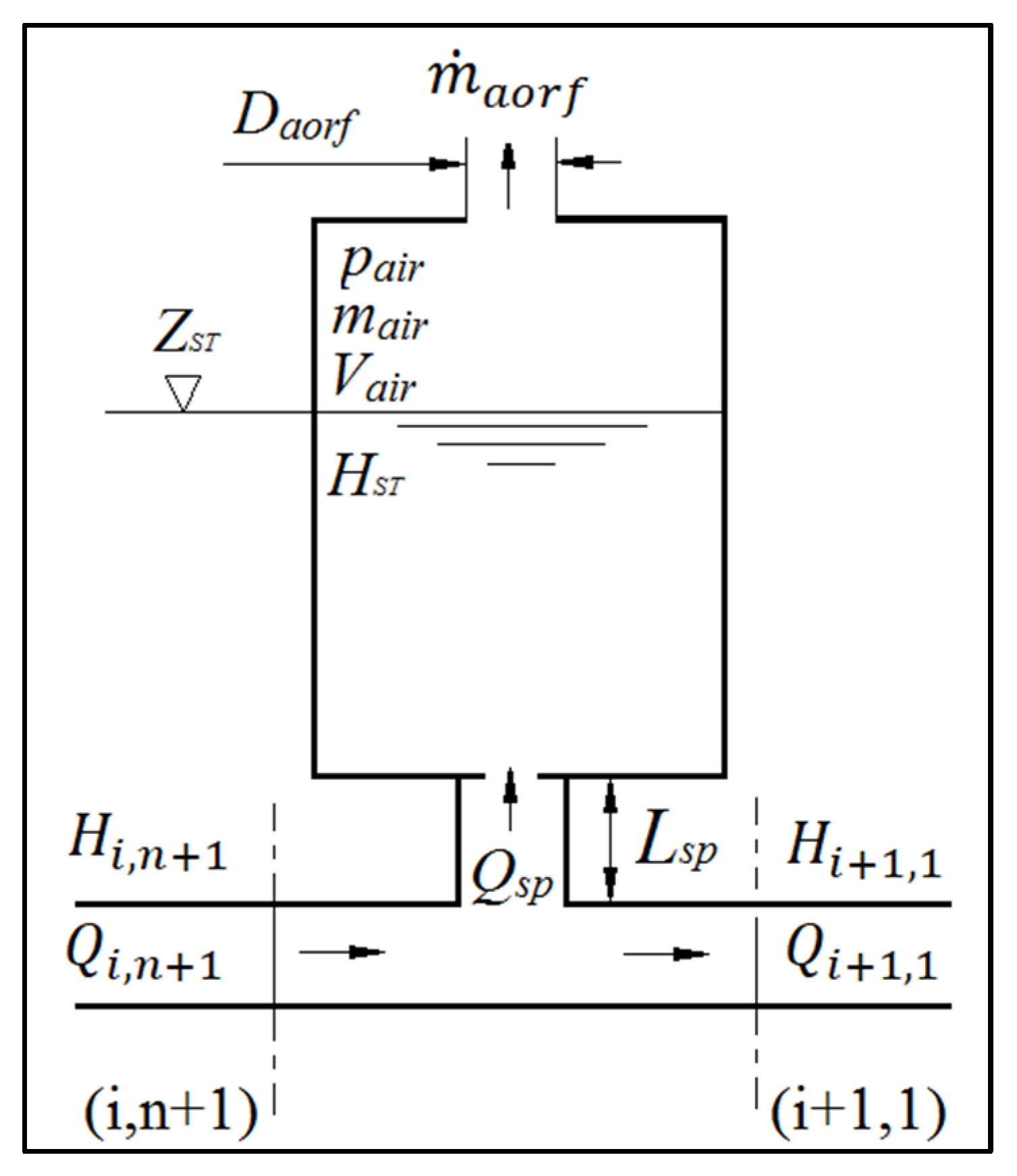
2. Mathematical Model of the Semi-Pneumatic Surge Tank

The following mathematical model of the SPST is defined as a boundary condition in the original software developed at the University of Belgrade, Faculty of Mechanical Engineering, based on the Method of Characteristics (MOC). The scheme of the cylindrical semi-pneumatic surge tank is shown in Figure 1.
The system of equations includes positive and negative characteristics (Equations (1) and (2)), losses in junction that are considered negligible (Equation (3)), and continuity equation (Equation (4)) defined for the branching junction [34],
Q P i ,   n + 1 = C P i g A i a i H P i , n + 1
Q P i + 1 , 1 = C N i + 1 + g A i a i H P i + 1 , 1
H P i , n + 1 = H P i + 1 , 1
Q P i , n + 1 = Q P i + 1 , 1 + Q P s p
where: Q is discharge and H is head at the defined point on the pipe upstream and downstream, indexes P and SP are related to the next time step and standpipe, respectively. Coefficients CP and CN are calculated from the previous time step through the following relations (Equations (5) and (6)):
C P i = Q i , n + g A i a i H i , n λ i t 2 D i A i Q i , n | Q i , n |
C N i + 1 = Q i + 1 , 2 g A i + 1 a i + 1 H i + 1 , 2 λ i + 1 t 2 D i + 1 A i + 1 Q i + 1 , 2 | Q i + 1 , 2 |
where: g is gravity acceleration, λ is friction coefficient, ∆t is time step, D is pipe diameter, A is cross-section area and a is wave propagation speed. It is assumed that the air behaves in a polytropic manner where mass changes should be included (Equation (7)):
H P a i r * V P a i r n m P a i r n = const .
where: H P a i r * is absolute pressure head, V P a i r and m P a i r are the volume and the mass, respectively, of the air in the SPST at time step P and n is polytropic exponent. The dynamic equation for the standpipe at the end of the time step is defined by Equation (8) as a lumped inertia model including friction with adequate modifications to use in MOC [12]:
Q P s p = Q s p + g t A s p L s p ( H P i , n + 1 H P a i r * H P S T ) + g t A s p L s p ( H a t m ( λ s p L s p 2 g D s p A s p 2 + C s p ) Q s p | Q s p | )
where: L s p is standpipe length, H P S T is the surge tank head for the next time step P,   λ s p and C s p are the friction and minor losses coefficients of the standpipe which also includes the possibility of orifice positioning. The head of the surge tank for the next time step is defined by Equation (9):
H P S T = H S T + 0.5 ( Q P s p + Q s p ) t A S T
where: A S T is the cross-sectional area of the surge tank. Mass of the air expelled through aeration orifice m ˙ a o r f is defined by Wylie & Streeter [12] as subsonic in-flow, critical in-flow, subsonic out-flow and critical out-flow (Equation (10)), respectively:
m ˙ a o r f = { C i n , a o r f A i n , a o r f 7 p 0 * ρ 0 [ ( p a i r * p 0 * ) 1.4286 ( p a i r * p 0 * ) 1.714 ]      p 0 * > p a i r * > 0.53 p 0 * C i n , a o r f A i n , a o r f 0.686 R T 0 p 0 *                                  p a i r * < 0.53 p 0 * C o u t , a o r f A o u t , a o r f p a i r * 7 R T a i r [ ( p 0 * p a i r * ) 1.4286 ( p 0 * p a i r * ) 1.714 ]   p 0 * 0.53 > p a i r * > p 0 * C o u t , a o r f A o u t , a o r f 0.686 R T a i r p a i r *                               p a i r * > p 0 * 0.53  
where: C i n / o u t , a o r f is discharge coefficient of the aeration orifice inlet/outlet, A i n / o u t , a o r f is cross-sectional area of the aeration orifice inlet/outlet, p 0 * and ρ 0 are absolute pressure and mass density of atmospheric air, respectively, and p a i r * and T a i r are absolute pressure and temperature of the air inside the SPST. The mass and volume of the air in the SPST are defined by Equations (11) and (12).
m P a i r = m a i r + m ˙ a o r f t
V P a i r = V a i r 0.5 ( Q P s p + Q s p ) t
The defined non-linear system of equations may be solved by various adequate methods and in this case the Newton-Raphson method has been applied [35]. The main difference between the mathematical models of the cylindrical and chamber-type SPSTs is a correct definition of diameter change during the transient process considering surge tank water level and different initial conditions based on the existence of the upper and lower chamber.

3. Case Study

HPP Pirot, which is considered in this research, is a derivation-type HPP with a tunnel and a penstock approximately 8.6 km and 2 km long, respectively [2]. HPP Pirot is equipped with two Francis turbines of the rated output 2 × 40 MW, synchronous speed of 500 rpm and rated discharge of 2 × 22.8 m3 s−1 with synchronous pressure relief valves (PRVs) on their casings. The surge tank is located at the downstream end of the tunnel section (Figure 2).
The existing surge tank is an open-air throttled-orifice chamber type (TCST) with two chambers and an orifice in the standpipe (Figure 3a). Subsequently, the analyses have been conducted with four different approaches. The mathematical models of the TCST and semi-pneumatic throttled chamber type surge tank (SPTCST) for the same structural parameters have been compared. This is followed by an analysis of various dimensions of the aeration orifice and their effects on the water-mass oscillations. Depending on the different vertical positioning of the aeration orifice, the obtained results have also been presented. Further on, possible dimension reduction of the surge tank through “pneumatisation” has been considered. Regarding the common standard operating regimes for the investigation of the transient processes, a maximum upper reservoir level of 615.00 m a.s.l. has been chosen for the load rejection case. For the cases of simultaneous turbines start, a minimum upper reservoir level of 568.00 m a.s.l. has been adopted. Tailwater elevation varies insignificantly around 370 m a.s.l.

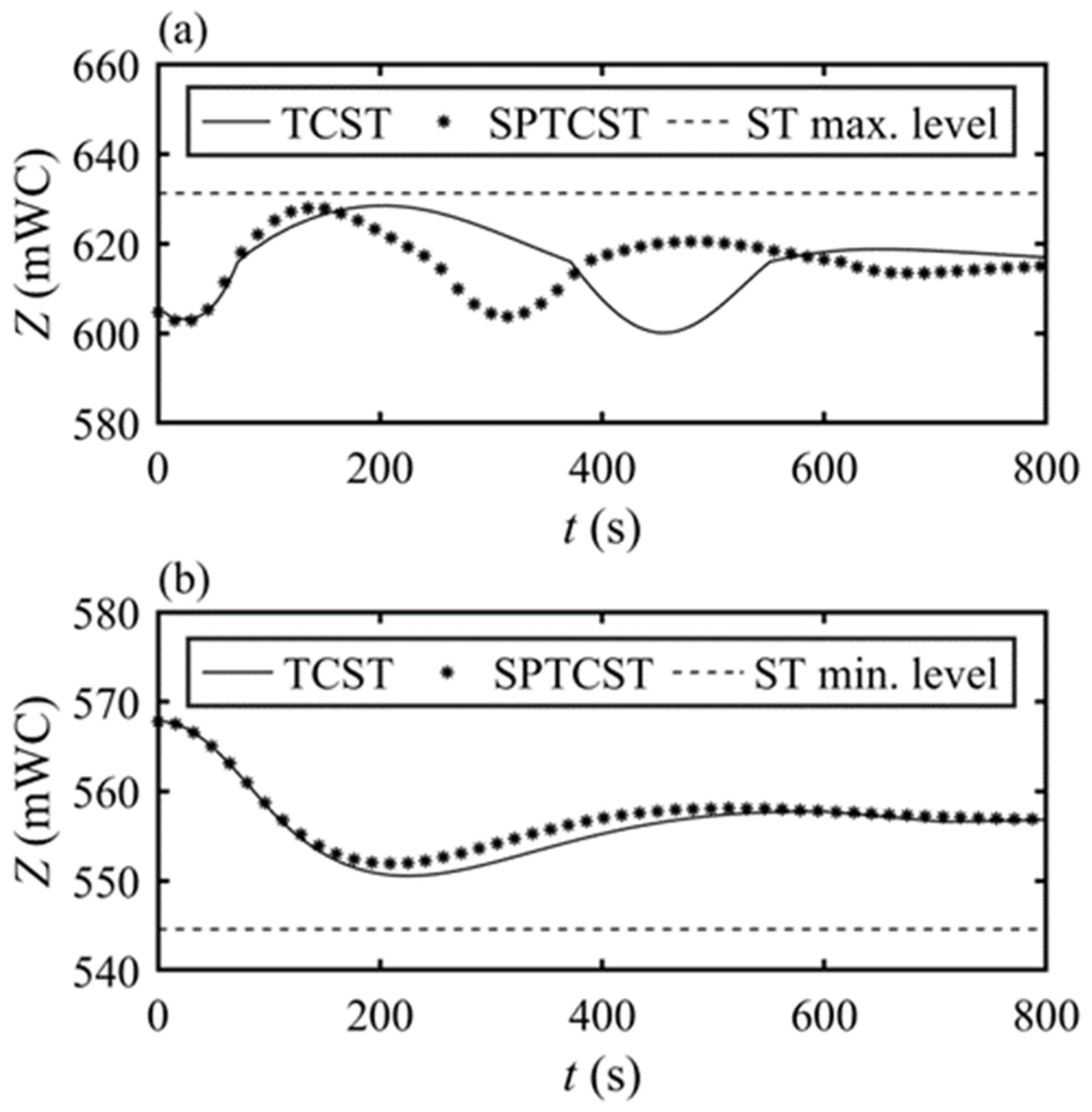
3.1. Comparison of the Surge Tanks for the Same Structural Parameters

The mathematical model for the TCST is a part of the previously developed, repeatedly tested and reliable original software [36]. The SPST model results were compared with the results obtained for the same structural parameters of the surge tank already installed in HPP Pirot. The mathematical model of the SPTCST (Figure 3b) has been defined with the aeration orifice diameter of 15 m which is equivalent to the upper chamber diameter. Namely, the structural characteristics of the SPTCST are the same as in the TCST model. Comparative analysis for the load rejection (linear guide vanes closing law in 9 s and complementary opening law of the synchronous pressure regulation valves; rated discharge of 2 × 20 m3/s) and simultaneous start (linear guide vanes opening law in 90 s from speed-no-load 2 × 2.8 m3/s to the rated discharge 2 × 20 m3/s) of both turbines is illustrated in Figure 4.
Results of the load rejection and simultaneous turbine start for the chamber-type and semi-pneumatic surge tank practically coincide for the same structural parameters. Regarding the other parameters of importance, such as pressure envelopes along the disposition, turbine spiral casing and draft tube head, turbine rotational speed during load rejection and turbine discharge, there is also no difference.

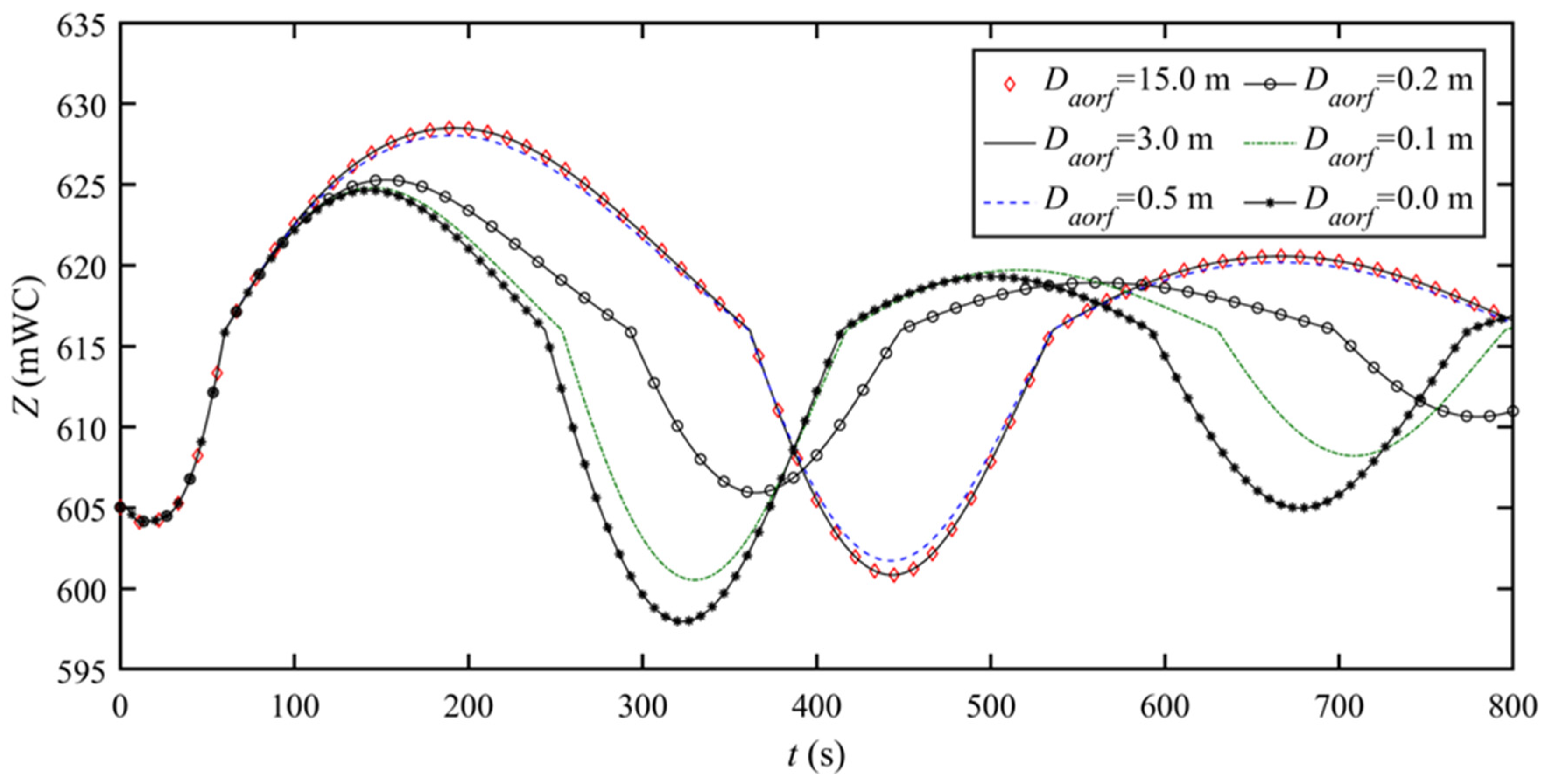
3.2. Comparison of Various Aeration Orifice Dimensions

Dimensions and shape of the aeration orifice are defined by the equivalent diameter ( D a o r f ) and discharge coefficient of the aeration orifice inlet/outlet ( C i n / o u t , a o r f ) and have a direct effect on the air pressure and the surge tank water level (STWL) during the transient process.
For the analyzed case, the value of the discharge coefficient is set to 0.9. Considering the possibility to modify the cross-sectional area value of the orifice (Equation (10)), the effects of the various values of the discharge coefficient for the round and symmetrical aeration orifice can be neglected. Due to the aeration orifice diameter modification, the discharge coefficient was not defined as the main parameter of the researched SPST. Although the variation-induced effects can be neglected, the actual effects should not be overlooked for the SPST application. The correct real value of the discharge coefficient should be defined depending on the aeration orifice shape. Since the isothermal behavior of the air is to be expected, the polytropic exponent value was set to 1. Various dimensions of the aeration orifice diameter have been researched and their influence is presented in Figure 5 and Figure 6 for cases of both load rejection and simultaneous start.
In the case of load rejection of both turbines, the absolute air pressure ranges from the atmospheric pressure ( D a o r f = 3 ÷ 15   m ) to 270 kPa ( D a o r f = 0   m ) .
For the case of simultaneous start, the absolute air pressure varies from the atmospheric pressure ( D a o r f = 3 ÷ 15   m ) down to 65 kPa ( D a o r f = 0   m ) .

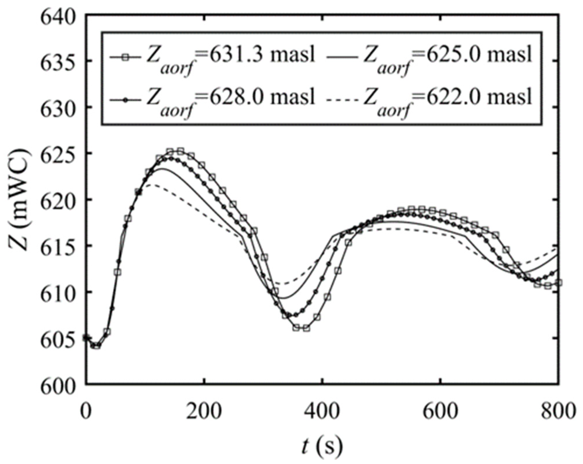
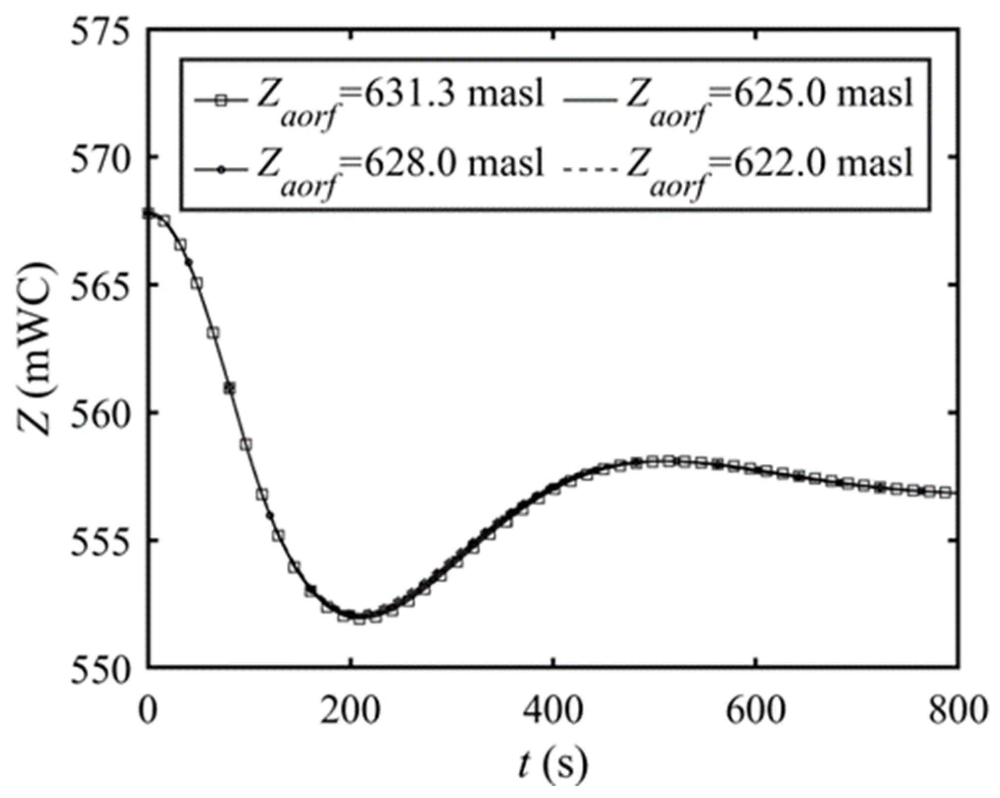
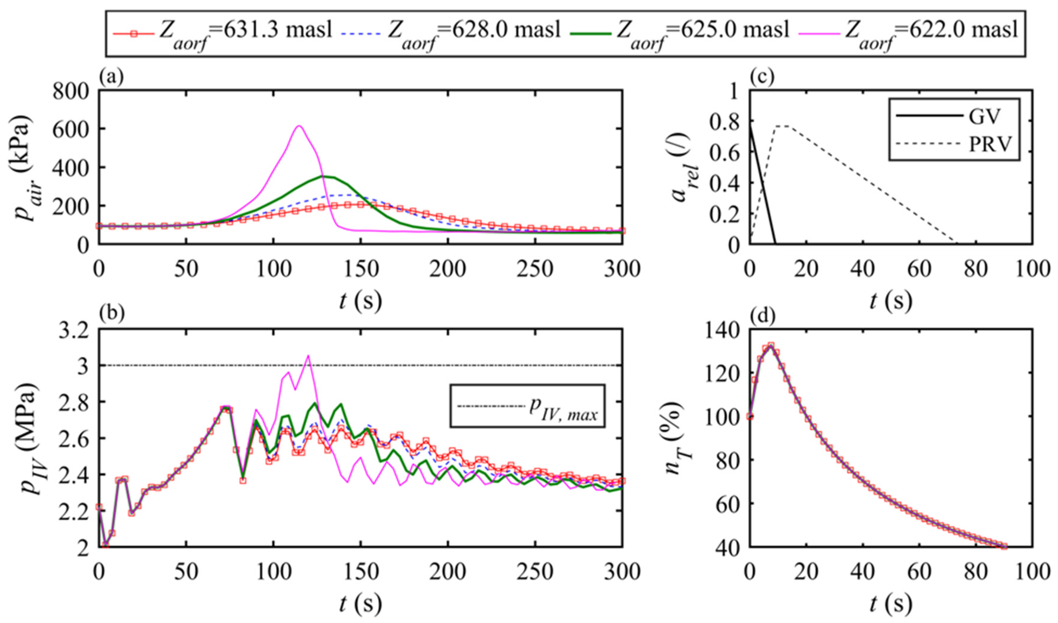
3.3. Vertical Positioning of the Aeration Orifice

Vertical positioning of the aeration orifice may further improve SPST characteristics.
Here, the aeration orifice of 0.2   m in diameter, which is considered to be favourable, has been positioned at different specific levels in the surge tank, such as 619, 622, 625, 628 and 631.3 m a.s.l. According to the numerical simulations, the obtained results demonstrate an overflow of water through the aeration orifice for its position below 622 m a.s.l. Results for the cases considered safe, without overflow, are presented in Figure 7 for the load rejection of both turbines and in Figure 8 for the cases of simultaneous turbines start.
It is noticeable that the air pressure in the SPTCST is rapidly increasing depending on the vertical position of the aeration orifice (Figure 9a) regarding the lower pressure fluctuations for the changes in the orifice diameter when it is placed on the top.
Intensive air pressure rise in the SPST has an effect on the whole derivation system and needs to be further investigated both in the low-pressurized section (accumulation-tunnel-surge tank) and in the high-pressurized section (surge tank-penstock-turbine). As an example, results of the WH analyses for the load rejection of both turbines, for the various vertical positions of the aeration orifice, are presented in Figure 9. Figure 9b illustrates pressure in the inlet valves whereas the transient rotational speed of the turbines is presented in Figure 9d for the defined closing/opening law of the guide vanes/PRVs (Figure 9c).

3.4. Optimization of the Semi-Pneumatic Surge Tank

With the aim of considering the real HPP operation improvements and decrease in the initial investment costs, achieved by using the SPST, the analysis of possible SPST dimension reduction has been performed.
Figure 10 shows that not only the existing TCST of the original dimensions but also the optimized SPTCST satisfy the acceptance criteria for the implementation both during load rejection and simultaneous start. Therefore, it is evident that installing an SPST, with the diameter of the upper and lower chamber of 12 m (20% smaller diameter) and the core with the diameter of 7 m (diameter reduction of 12.5%), was possible instead of the currently installed one.
The obtained results imply the surge tank complete volume decrease possibility of about 33% in the design phase in favour of the SPTCST. For the presented case, the adopted aeration orifice diameter is 0.2 m.

4. Discussion

The previous section investigates the comparison between chamber-type and semi-pneumatic surge tanks for the same structural parameters. The mathematical model for the chamber-type surge tank is a part of the formerly developed and experimentally verified software that has been used in numerous projects. With the aim of initial validation of the developed SPST model, the conditions have been accomplished by defining the equivalent diameter of the aeration orifice, i.e., the upper chamber diameter of the chamber-type surge tank is 15 m (Figure 3a) as well as the aeration orifice dimensions ( D a o r f = 15   m , Figure 3b). The results of the simultaneous turbine start and load rejection for the chamber-type and semi-pneumatic surge tank almost match (Figure 4). The mathematical model of the SPST confirms that the air pressure changes remain equal to the atmospheric pressure, as expected.
For the large closed surge tanks, Chaudhry [34] recommends isothermal process in the air, whereas Vereide, Lia & Nielsen [1] suggest the adiabatic process for the pneumatic surge tanks, noting that different thermodynamic behavior should be expected depending on the size, construction material and period of mass oscillations. Considering that the ST of the HPP Pirot is relatively large with the low-frequency pressure and discharge oscillations, isothermal air behavior should be expected and defined with polytropic exponent value n = 1. Regarding the behavior of air in the SPST, sensitivity analyses of the polytropic exponent changes confirm negligible influence in the researched case but should be considered on the HPPs with smaller STs.
The above analyses were followed by investigations of the various dimensions of the aeration orifice diameter. The STWL of the SPST for the various values of the aeration orifice diameter is presented in Figure 5 and Figure 6 for the load rejection and simultaneous turbines starts, respectively. The implementation of the aeration orifice with a diameter lower than D a o r f = 3   m , affects the reduction of the STWL. In the cases of D a o r f = 3 ÷ 0.2   m , reduction of the aeration orifice diameter reduces maximum and minimum STWL values. For the analysed range of orifice dimensions, the WMOs characteristics have the same trend as the ones during the increase of the minor losses with the orifice in the standpipe. Hence, during the increase of the minor losses in the standpipe, the water hammer effect in the high-pressurized section (surge tank-penstock-turbine) may be reflected in the low-pressurized section (accumulation-tunnel-surge tank). The aeration orifice diameter range D a o r f = 0.2 ÷ 0   m for the load rejection has a positive impact on the maximum STWL value although slightly negative for the value of minimum STWL. The fact that the relatively small diameter of the aeration orifice does not allow enough energy dissipation while the air remains highly pressurized leads to negative effects afterwards, which is in accordance with the same trend for the pneumatic surge tanks. According to the dependence of the transient processes analyses on surge tank characteristics, quick-restarts are the most extreme cases of minimum STWL. Therefore, the analyses should be thoroughly performed before the aeration orifice diameter adoption in order to completely prevent air suction [2].
Along with the correct dimensioning of the aeration orifice diameter, its vertical positioning in the surge tank has also been researched. The decrease in STWL is achieved by lowering the aeration orifice level in the surge tank. Since the air pressure rises rapidly in the previous case, the proper choice of the vertical position during an HPP revitalization depends on the structural characteristics of the existing surge tank and the whole derivation system both in high-pressurized and low-pressurized HPP sections, or it has to be taken into account in the design phase.
Further on, the surge tank dimension reduction has also been analyzed to allow possible SPST implementation instead of the currently used open-air chamber-type.
Bearing in mind the presented case with an already installed surge tank, its modification into the SPST type may be practically debatable because its top is at the ground level. On the other hand, the presented methodology showcases the good SPST capabilities and purposefulness. According to the comparative analysis (Figure 10) of the optimized SPST and the existing one, the STWL and the pressure in the IVs is acceptable for both the simultaneous turbine start and load rejection. Thus, for economically justified reasons, the new surge tank dimensions with specific aeration orifice could be smaller than the ones previously defined: both the diameter of the optimized upper and lower chamber and the core could be by 20% and by 12.5% smaller, respectively.

5. Conclusions

Surge tanks are often an irreplaceable and indispensable protection measure facilitating the safe and reliable operation of the derivation-type HPPs. The choice of tank type and dimensions usually greatly influences the initial investment costs, so the focus of this paper was to find a more rational approach by applying the semi-pneumatic surge tanks. The advantage of such tanks could be noticeable by direct implementation of aeration orifice onto the open-air surge tanks in the existing or new HPPs. Since the detailed analyses of SPST have never been conducted up to now, research on the SPSTs has for the first time been carried out by detailed theoretical considerations, a newly developed mathematical model and comprehensive numerical simulations.
The mathematical model of the semi-pneumatic surge tank combined with the corresponding numerical simulations for the specific HPP has been presented. The obtained results contribute to the thorough understanding of the transient processes in the SPSTs highlighting their better performance in relation to the basic-type open-air surge tank. SPST implementation will shorten the time required to achieve newly defined quasi-steady states. The numerical simulations of the SPST are the first phase in the forthcoming research of this insufficiently described and for a long neglected type of surge tank. The confirmation, calibration and improvement of the developed model by data measuring is the next phase of the planned researches, for which experimental setups are being prepared. Special attention will be paid to the detailed analysis of the air behaviour utilizing the rational heat transfer method and its modified version in a laboratory and in situ conditions. Further research will also focus on the stability analyses of a novel SPST. For this purpose, turbines’ governing system with a PID controller is going to be modelled, validated and verified for a specific HPP taking into account various power network (speed regulation) disorders and including different demands on power change (power regulation). The implementation of SPST will shorten the time required to achieve newly defined quasi-steady states.

Author Contributions

Conceptualization, J.I. and A.P.; Data curation, J.I.; Formal analysis, J.I. and A.P.; Funding acquisition, I.B. and U.K.; Investigation, J.I.; Methodology, J.I.; Project administration, I.B.; Resources, I.B. and U.K.; Software, J.I. and A.P.; Supervision, I.B. and U.K.; Validation, J.I., A.P. and U.K.; Visualization, I.B. and U.K.; Writing—original draft, J.I.; Writing—review & editing, I.B., A.P. and U.K. All authors have read and agreed to the published version of the manuscript.

Funding

This research received no external funding.

Acknowledgments

The authors gratefully acknowledge the support of the Ministry of Education, Science and Technological Development of the Republic of Serbia and the Ministry of Science of Montenegro through the bilateral project “Research and development of improved measures for protection of hydropower plants during hydraulic transients in order to increase their reliability and energy efficiency” and Public Enterprise “Elektroprivreda Srbije”—“Hydropower plants Djerdap” Branch, especially HPP “Pirot”. The presented research is also supported by the Ministry of Education, Science and Technological Development of the Republic of Serbia (Contract № 451-03-9/2021-14/200105 dated 5 February 2021).

Conflicts of Interest

The authors declare no conflict of interest.

Abbreviations

Notation
a = wave propagation speed (m s−1)
A = cross sectional area (m2)
arel = relative opening/closing (/)
C = minor loss coefficient (-)
CN = coefficient defined in the negative equation of the Method of Characteristics (m3 s−1)
CP = coefficient defined in the positive equation of the Method of Characteristics (m3 s−1)
D = diameter (m)
g = gravity acceleration (m s−2)
H = head (m)
H* = absolute pressure head (m)
L = length (m)
m = mass (kg)
m ˙ = mass discharge (kg s−1)
n = polytropic exponent (-)
nT = transient turbine revolving speed (%)
p* = absolute pressure (Pa)
p = gauge pressure (Pa)
Q = discharge (m3 s−1)
R = specific gas constant (J kg−1 k−1)
T = temperature (k)
V = volume (m3)
Z = elevation (m a.s.l. for the object, mWC for fluid)
t = time step (s)
λ = friction loss coefficient (-)
ρ = density of water (kg m−3)
Abbreviations
CSTclosed surge tank
HOSChydraulic oscillations
HPPhydropower plant
IVinlet valve
LGOVlevel governing
MOCmethod of characteristics
OPCHopen channel
PRVpressure relief valve
SPSTsemi-pneumatic surge tank
SPTCSTsemi-pneumatic throttled chamber type surge tank
STsurge tank
STWLsurge tank water level
TCSTthrottled chamber type surge tank
TGOVturbine governing
WHwater hammer
WMOwater-mass oscillations

References

  1. Vereide, K.; Lia, L.; Nielsen, T. Hydraulic scale modelling and thermodynamics of mass oscillations in closed surge tanks. J. Hydraul. Res. 2015, 53, 519–524. [Google Scholar] [CrossRef] [Green Version]
  2. Ilić, J.; Petković, A.; Božić, I. Numerical analyses of water hammer and water-mass oscillations in a hydropower plant for the most extreme operational regimes. FME Trans. J. 2019, 47, 7–15. [Google Scholar] [CrossRef]
  3. Fathi-Moghadam, M.; Haghighipour, S.; Mohammad Vali Samani, H. Design-variable optimization of hydropower tunnels and surge tanks using a genetic algorithm. J. Water Resour. Plan. Manag. 2013, 139, 200–208. [Google Scholar] [CrossRef]
  4. Gabl, R.; Righetti, M. Design criteria for a type of asymmetric orifice in a surge tank using CFD. Eng. Appl. Comput. Fluid Mech. 2018, 12, 397–410. [Google Scholar] [CrossRef] [Green Version]
  5. Ilić, J.; Božić, I.; Karadžić, U.; Brđanin, R. Comparative analysis of the hydropower plant transient processes for various surge tank types and improved guide vanes closing law. In Proceedings of the 14th International Conference on Achievements in Mechanical and Industrial Engineering—DEMI 2019, Banja Luka, Bosnia and Herzegovina, 24–25 May 2019. [Google Scholar]
  6. Michaud, J. Coups de bélier dans les conduites. Étude des moyens employés pour en atteneur les effects [Water hammer in pipelines. Principles of studying the effects]. Bull. Soc. Vaud. Ingénieurs Archit. 1878, 4, 56–64, 65–77. [Google Scholar]
  7. Johnson, R.D. The surge tank in water power plants. Trans. ASME 1908, 30, 443–474. [Google Scholar]
  8. Thoma, D. Theorie des Wasserschlosses bei Selbsttätig Geregelten Turbinenanlagen [Theory of the Water Hammer in Self-Regulated Hydropower Plants]. Doctoral Dissertation, Kgl. Technische Hochschule zu München, Munich, Germany, 1910. [Google Scholar]
  9. De Sparre, M. Des coups de belier dans les conduits [Water hammer in pipelines]. La Houille Blanche 1911, 10, 257–263, 293–298, 316–317. [Google Scholar]
  10. Camichel, C. Recherches sur les conduits possédant des reservoirs d’air [Research on the pipelines with the air-cushion reservoirs]. Ann. Fac. Sci. Toulouse 1918, 10, 221–259. [Google Scholar] [CrossRef]
  11. Svee, R.H. Surge chamber with an enclosed, compressed air-cushion. In Proceedings of the 1st International Conference on Pressure Surges, Bedford, UK, 6–8 September 1972. [Google Scholar]
  12. Wylie, E.B.; Streeter, V.L. Fluid Transients in Systems; Prentice-Hall: Englewood Cliffs, NJ, USA, 1993. [Google Scholar]
  13. Thorley, A.R.D. Fluid Transients in Pipeline Systems; Professional Engineering: London, UK, 2004. [Google Scholar]
  14. Graze, H.R. A rational thermodynamic equation for air chamber design. In Proceeding of the 3rd Australian Conference Hydraulics and Fluid Mechanics, Sydney, Australia, 25–29 November 1968. [Google Scholar]
  15. Vereide, K.; Tekle, T.; Nielsen, T.K. Thermodynamic behaviour and heat transfer in closed surge tanks for hydropower plants. J. Hydraul. Eng. 2015, 141, 06015002. [Google Scholar] [CrossRef] [Green Version]
  16. Gabl, R.; Gems, B.; Plorer, M.; Klar, R.; Gschnitzer, T.; Achleitner, S.; Aufleger, M. Numerical Simulations in Hydraulic Engineering. In Computational Engineering; Springer: Cham, Switzerland, 2014; pp. 195–224. [Google Scholar]
  17. Torlak, M.; Bubalo, A.; Džaferović, E. Numerical analysis of water elevation in a hydropower plant surge tank. In Proceedings of the 6th IAHR Meeting of the Working Group “Cavitation and Dynamic Problems in Hydraulic Machinery and Systems”, Ljubljana, Slovenia, 9–11 September 2015. [Google Scholar]
  18. Bhattarai, K.; Zhou, J.; Palikhe, S.; Pandey, K.; Suwal, N. Numerical modeling and hydraulic optimization of a surge tank using particle swarm optimization. Water 2019, 11, 715. [Google Scholar] [CrossRef] [Green Version]
  19. Dhakal, R.; Zhou, J.; Palikhe, S.; Bhattarai, K. Hydraulic optimization of double chamber surge tank using NSGA-II. Water 2020, 12, 455. [Google Scholar] [CrossRef] [Green Version]
  20. Vereide, K.; Richter, W.; Zenz, G.; Lia, L. Surge tank research in Norway and Austria. Wasserwirtschaft 2015, 105, 58–62. [Google Scholar] [CrossRef] [Green Version]
  21. Richter, W.; Vereide, K.; Zenz, G. Optimizing surge tank layout for highly flexible hydropower. Int. J. Hydropower Dams 2018, 25, 42–46. [Google Scholar]
  22. Doerfler, P.; Lein, G. Stable operation of reduced size surge tanks. Int. J. Hydropower Dams 2001, 8, 108–112. [Google Scholar]
  23. Yu, X.; Zhang, J.; Zhou, L. Hydraulic transients in the long diversion-type hydropower station with a complex differential surge tank. Sci. World J. 2014, 2014, 241868. [Google Scholar] [CrossRef] [PubMed] [Green Version]
  24. Sandvag, S.U. Surge Tank Atlas for Hydropower Plants. Master’s Thesis, University of Science and Technology, Trondheim, Norway, 2016. [Google Scholar]
  25. Муравьёв, O.A. Уравнительные резервуары [Surge Tanks]; НИУ МГСУ: Moscow, Russia, 2017. [Google Scholar]
  26. Escande, L. The stability of throttled surge tanks operating with the electric power controlled by the hydraulic power. J. Hydraul. Res. 1963, 1, 4–13. [Google Scholar] [CrossRef] [Green Version]
  27. Jaeger, C. Fluid Transients in Hydro-Electric Engineering Practice; Blackie: Glasgow, UK, 1977. [Google Scholar]
  28. Adam, N.; De Cesare, G.; Nicolet, C.; Billeter, P.; Angermayr, A.; Bernard, V.; Schleiss, A. Design of a throttled surge tank for the refurbishment by power increase of a high head power plant. J. Hydraul. Eng. 2018, 144, 05017004. [Google Scholar] [CrossRef]
  29. Đorđević, B. Korišćenje Vodnih Snaga [The Use of Water Power]; University of Belgrade Faculty of Civil Engineering: Belgrade, Serbia, 1989. [Google Scholar]
  30. Щавелев, Д.С.Васильев, Ю.С.; Претрo, Г.А.; Резникoвский, А., Ш. Гидрoэнергетические Устанoвки [Hydroelectric Installations]; Энергия: Moscow, Russia, 1972. [Google Scholar]
  31. Аршеневский, H.; Губин, Ф.; Губин, М.; Кривченкo, Г. Гидрoэлектрические Станции [Hydropower Stations]; Энергия: Moscow, Russia, 1980. [Google Scholar]
  32. Fitzgerald, R.; Van Blaricum, V.L.; Water Hammer and Mass Oscillation (WHAMO) 3.0 User’s Manual. USACERL ADP Report USACERL-ADP-98/129. 1998. Available online: https://erdc-library.erdc.dren.mil/jspui/bitstream/11681/13746/1/CERL-ADP-98-129.pdf (accessed on 3 February 2022).
  33. Brđanin, R.; Ilić, J.; Karadžić, U.; Božić, I. Experimental water hammer setup at University of Montenegro—Description and possibilities. In Proceedings of the 14th International Conference on Achievements in Mechanical and Industrial Engineering—DEMI 2019, Banja Luka, Bosnia and Herzegovina, 24–25 May 2019. [Google Scholar]
  34. Chaudhry, M.H. Applied Hydraulic Transients; Springer: New York, NY, USA, 2014. [Google Scholar]
  35. Verbeke, J.; Cools, R. The Newton-Raphson method. Int. J. Math. Educ. Sci. Technol. 1995, 26, 177–193. [Google Scholar] [CrossRef]
  36. Ilić, J. Prelazni Procesi u Hidroelektranama—Modeliranje, Numeričke Simulacije i Analize Normalnih, Posebnih i Havarijskih Radnih Režima [Hydraulic Transients in Hydropower Plants—Modelling, Numerical Simulations and Analyses of Normal, Special and Emergency Working Regimes]. Master’s Thesis, University of Belgrade Faculty of Mechanical Engineering, Belgrade, Serbia, 2017. [Google Scholar]
Figure 1. Cylindrical semi-pneumatic surge tank scheme.
Applsci 12 02353 g001
Figure 2. HPP Pirot scheme.
Applsci 12 02353 g002
Figure 3. HPP Pirot: (a) throttled chamber surge tank and (b) semi-pneumatic surge tank developed for the comparison (levels are indicated in m a.s.l.).
Applsci 12 02353 g003
Figure 4. STWL of the throttled chamber and semi-pneumatic throttled chamber surge tank for (a) load rejection and (b) simultaneous start of both turbines.
Applsci 12 02353 g004
Figure 5. Load rejection—STWL for the semi-pneumatic throttled chamber surge tank for various aeration orifice diameters.
Applsci 12 02353 g005
Figure 6. Simultaneous start—STWL of the semi-pneumatic throttled chamber surge tank for various aeration orifice diameters.
Applsci 12 02353 g006
Figure 7. Load rejection—STWL of the semi-pneumatic throttled chamber surge tank for various vertical positions of the aeration orifice.
Applsci 12 02353 g007
Figure 8. Simultaneous start—STWL of the semi-pneumatic throttled chamber surge tank for various vertical positions of the aeration orifice.
Applsci 12 02353 g008
Figure 9. Vertical positioning of the aeration orifice at 631.3; 628.0; 625.0; 622.0 m a.s.l. (a) air pressure in the SPTCST, (b) pressure on turbine inlet valve, (c) closing/opening law of guide vanes/PRV and (d) transient turbine revolving speed.
Applsci 12 02353 g009
Figure 10. STWL for the throttled chamber and optimized semi-pneumatic throttled chamber surge tank for (a) load rejection and (b) simultaneous start of both turbines.
Applsci 12 02353 g010
Publisher’s Note: MDPI stays neutral with regard to jurisdictional claims in published maps and institutional affiliations.

