Article

Analysis of Stability and Required Offset with Vibration Velocity Considering Conditions of Bedrock and Explosive Charges Using the TBM and NATM Extension Blasting Method

Department of Geotechnical Engineering Research, Korea Institute of Civil Engineering and Building Technology, Goyang-si 10223, Korea
*
Author to whom correspondence should be addressed.
Appl. Sci. 2022, 12(7), 3473; https://doi.org/10.3390/app12073473
Submission received: 17 January 2022 / Revised: 24 March 2022 / Accepted: 28 March 2022 / Published: 29 March 2022
(This article belongs to the Section Civil Engineering)

Abstract

:
The development of underground spaces in urban centers has attracted significant research attention. Typical excavation methods for underground spaces in urban areas include the New Austrian tunneling method (NATM) and the tunnel boring machine (TBM). The NATM is superior in terms of ease of construction and economic efficiency; however, vibration and noise are often cited as major complaints. In addition to their high initial cost, TBMs require intricate analyses of ground conditions during excavation. To overcome the disadvantages of both methods and reduce construction time, a TBM and NATM parallel excavation method has recently been investigated. In this study, the effects of blasting vibrations on the TBM, TBM backup device, and surrounding ground were examined during an NATM application for rear expansion blasting after pilot tunnel excavation using a TBM. Different rock types and powder factors were simulated, and differences in the vibration velocity according to their variations were predicted using 3D numerical analysis.

1. Introduction

Underground tunnels can be excavated in a variety of ways, and their construction has continuously evolved. Tunneling methods can be classified into two categories: conventional and mechanized. Numerous tunneling projects have been completed in South Korea using the New Austrian tunneling method (NATM), which is a conventional tunneling method based on blasting. Blasting is an effective excavation method, but the vibrations and noise generated during the process affect the surrounding ground and structures and are a major source of complaints. To overcome these shortcomings, various approaches have been proposed, including the typical application of a tunnel boring machine (TBM) in conjunction with the NATM.
The TBM and NATM parallel excavation method has been recognized for its ability to combine the advantages of mechanical and blasting excavation methods. Additionally, a free surface can be achieved using a small-diameter TBM to excavate a pilot hole, which reduces vibration and noise because center-cut blasting, which is the main cause of vibration, can be eliminated. Furthermore, it is possible to investigate ground conditions before widening excavation using a TBM to create a pilot tunnel, which provides an opportunity to determine the appropriate steps to be taken based on rock conditions. Based on this analysis, different shapes and sizes can be applied during NATM widening excavation.
Currently, there is a lack of research on parallel excavation methods using TBM pilots and NATM widening. Studies on the effects of rear blasting on TBMs and pilot tunnels must also be conducted to determine the stability of this method and evaluate the extent to which construction periods can be shortened. Additionally, although there is a standard for permissible vibration aboveground, there is no standard for the vibration induced in underground spaces during excavation, which necessitates additional research.
Accordingly, this study employed numerical analysis to analyze the effects of vibration caused by blasting on a TBM, backup equipment, tunnel face, ground surface, and other components in the case of parallel excavation following pilot excavation using a TBM. Furthermore, the effects of various ground conditions with different rock types and explosive charges were compared.

2. Literature Review

Underground infrastructure demand is increasing as urbanization continues. Additionally, new excavation methods and equipment are constantly being developed for safer and more cost-effective construction. As a typical excavation method, the TBM excavation method has several advantages, including high excavation speed, excavation stability, minimal ground and environmental damage, and reduced noise and vibration. Therefore, its use in tunnel construction is increasing worldwide [1,2]. TBM tunneling requires the use of specific methods and equipment settings that are appropriate for the target site and ground conditions. Additionally, the initial cost is high using TBM. Therefore, further research on TBM tunneling is necessary [3,4,5,6].
The NATM is one of the most widely used excavation methods because of its simple execution, flexibility during construction, low cost, and ability to use a wide variety of support materials [7,8,9]. Since its introduction in 1952 in the Maggia-Electric project in Switzerland for the Lodano-Mosagno tunnel, which was constructed on unstable ground, NATM has been widely used [10]. Despite being used for many years, NATM has also been involved in many collapse accidents. A variety of causes contribute to collapse incidents, including unforeseen geological characteristics, planning and specification problems, calculation errors, construction problems, and management and control problems [11,12].
Therefore, various methods have been implemented, and research has been conducted to address these issues. The TBM and NATM parallel excavation method can be advantageous for identifying unforeseen geological characteristics using TBM pilot tunnels in advance of any collapse. Additionally, the aforementioned benefits of using TBM for excavation such as noise and vibration reduction can be retained, resulting in safer and more efficient construction. The excavation using TBM is difficult to have various shapes except for circular ones. In addition, when a large surface is required, the cost increases. The TBM and NATM parallel method can solve this problem. For this reason, projects using the TBM and NATM extension blasting method are increasing. Table 1 shows some examples of construction projects carried out in Korea using this method. However, indiscriminate NATM rear blasting without considering a TBM, preceding pilot tunnel, and surrounding ground may lead to accidents such as the collapse of the pilot tunnel and jamming of the TBM. Therefore, preconstruction studies and research are essential but are currently insufficient. It is necessary to study various conditions (ground type, powder factor, offset between blasting points and TBM, tunnel size, groundwater level, adjacent structures, etc.) before applying to the field. For these necessary basic studies, in this study, the applicability of the TBM and NATM parallel excavation method was improved. It was simulated according to the powder factor of explosives and ground conditions using numerical analysis. Through these results, it was confirmed that the vibration velocity occurring in the pilot tunnel, TBM, tunnel face, and ground surface decreased.
Underground blasting excavation sites are primarily located in urban areas, and because urban construction involves many aboveground and belowground structures, vibration and noise complaints are increasing. However, there are no regulations regarding vibrations that affect the ground and equipment—such as TBMs—during blasting, and there has been little research on this subject. Therefore, this study investigated the permissible standards for blasting in South Korea and abroad to compare them with numerical analysis results and assess the effectiveness of using a TBM and the NATM in parallel to reduce vibration. Table 2 summarizes the permissible blasting vibration standards set forth in tunnel standard specifications. Table 3 provides a summary of acceptable blasting standards used during the Seoul and Busan subway construction projects in South Korea [13,14].
Table 4 lists the standards for acceptable blasting vibration values in various countries [15]. The aforementioned South Korean domestic standards are generally stricter than foreign standards. Domestic standards specify permissible vibration values according to the materials and usage of a structure, whereas foreign standards specify values according to population density, frequency, and other factors.
Excavations using TBMs are generally considered vibration-free, and the vibration and noise created by the machine are deemed not to be a significant issue aboveground. A summary of the Final Environmental Impact Assessment Report from the “Access to the Region’s Core” project in New Jersey, USA, is provided in Table 5 [16]. This report contains vibration measurements taken aboveground for various TBM diameters, ground conditions, and drilling depths. Based on the information in Table 5, it is considered that vibration values that are lower than those generated by the TBM itself will have a low impact on the TBM.

3. Numerical Analysis

It is difficult to predict how the soil changes over time because it is an anisotropic material that behaves nonlinearly and constantly changes over time. Additionally, soil–structure interactions are extremely complex, making it impossible to determine building behaviors without performing a numerical analysis on the ground. This study examined the effects of vibrations generated during TBM pilot operations and NATM widening excavation on the TBM, TBM backup equipment, and surrounding ground using FLAC 3D [17]. FLAC 3D was developed by ITASCA as a three-dimensional continuum analysis program for the mechanical assessment of rock, soil, and structures; and it is capable of performing continuum analysis, discontinuous surface analysis, and mechanical-hydraulic coupling analysis considering fluid flow, as well as executing time-domain methods. This program performs well in dynamic analysis.

3.1. Modeling

As shown in Figure 1, the ground modeled using numerical analysis was simulated as a single ground object under three rock conditions: hard rock, soft rock, and weathered rock. The mesh for numerical analysis was set as shown in Figure 2. The mesh is divided into small pieces to derive reasonable results. Furthermore, the mesh around the tunnel was divided into smaller meshes than the mesh of the outside ground. In addition, according to the precautions provided by the program, the size of the adjacent mesh was created not to be more than doubled. The boundary conditions in the X-(both sides), Y-(digging direction), and Z-direction (lower edge of the ground model) of the modeled rock were set to the quiet boundary type in the FLAC 3D program to avoid the influence of reflected waves in all directions. Regarding the blasting load, vibration-controlled blasting was assumed based on the fact that the target ground area was located in the center of a city. However, according to the characteristics of the TBM and NATM parallel application method, expansion blasting was modeled only for the contour hole, excluding the center-cut blasting hole. The diameter of the tunnel expanded via NATM expansion blasting was 10.0 m and the diameter of the pilot tunnel excavated by the TBM was 5.0 m. Four types of explosive powder factors (2.0, 1.0, 0.75, and 0.5 kg) were applied to each blasting hole according to the rock type and separation distance, and numerical analysis was conducted for a total of 36 cases.
The constitutive models applied to the ground and TBM were the Mohr–Coulomb and elastic models, respectively. The physical properties of the ground used in this study were obtained from existing publications, and the physical properties of iron were used for the TBM [17,18,19]. An overview of the physical properties is provided in Table 6.

3.2. Blasting Load Calculation

In the context of numerical analysis, several empirical equations exist for calculating the blasting load. The blasting load in this study was calculated using the formula presented in [18], which is shown in Equation (1).
P D = 0.000424 V e 2 ρ e 1 0.543 ρ e + 0.193 ρ e 2
where, PD: Blasting load (kg cm−2); Ve: Average explosion velocity (m s−1); ρe: Average density (g cm−3).
The blasting load calculated in [20] was used to obtain the blasting loads for tamping and decoupling using Equations (2) and (3), and the equivalent blasting load (P’) was derived using Equation (4), as proposed by Starfield and Pugliese [21]. It is essential to consider the time history of the vibration generated by blasting before its application as a dynamic load. As shown in Equation (5), the history curve from [21] is commonly used to model the blast load time history.
P A = 2 ρ a C a ρ a C a + ρ e V e × P D
where, ρa: Dielectric flux density of sand (g cm−2); Ca: Propagation velocity of shockwaves (sand) (m s−1).
P B = d e d h 3 × P D
where, de: Explosive diameter (mm); dh: Borehole (mm).
P = P B × W × 2 π × D i a m e t e r   f o r   p e r f o r a t i o n   L e n g t h   a r o u n d   t h e   b l a s t   h o l e  
where, W: Charge per delay (kg).
P t = 4 P e x p B t 2 exp ( 2 Bt )
where, P(t): Pressure at time t (kg cm−2); B: Load constant (16,338); t: Arrival time (0.06 μs).
Figure 3 illustrates the time history curves calculated using Equation (5). The blasting loads applied in this study were 233.68, 350.51, 467.35, and 934.70 kg cm−2, which were equivalently converted into values during decoupling for powder factors of 0.5, 0.75, 1.0, and 2.0 kg, respectively [18,22]. In accordance with [23], a duration of 0.001 s, an equivalent frequency of 830 Hz, and a ground damping ratio of 1% were applied.

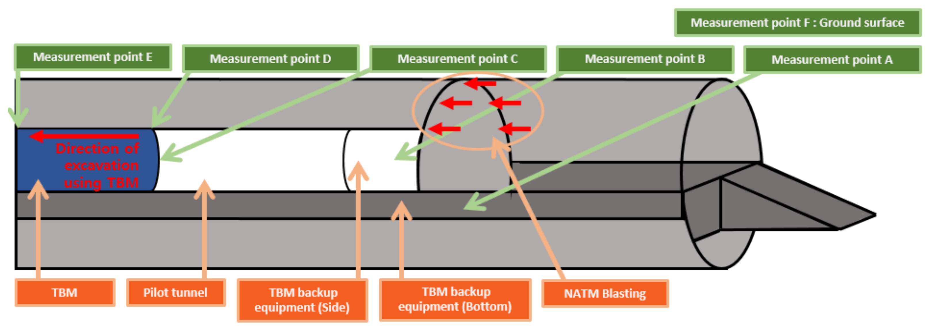
3.3. Analysis Case and Measurement Location

In this study, a numerical analysis was performed for NATM extension blasting after TBM pilot excavation according to tunnel length (4, 8, and 16 m), rock type (weathered rock, soft rock, and hard rock), and powder factor (0.5, 0.75, 1.0, and 2.0 kg). Table 7 presents a summary of the numerical analysis cases. As listed in Table 8, the vibration velocity for each case was measured at the TBM, ground above the TBM, TBM backup device (bottom and side), tunnel face, and ground surface (Figure 4).

4. Numerical Analysis Results

Below, we discuss the results obtained from the analysis of the effects of blasting vibration on the TBM, TBM backup device, and surrounding ground according to pilot tunnel length, rock type, and powder factor.

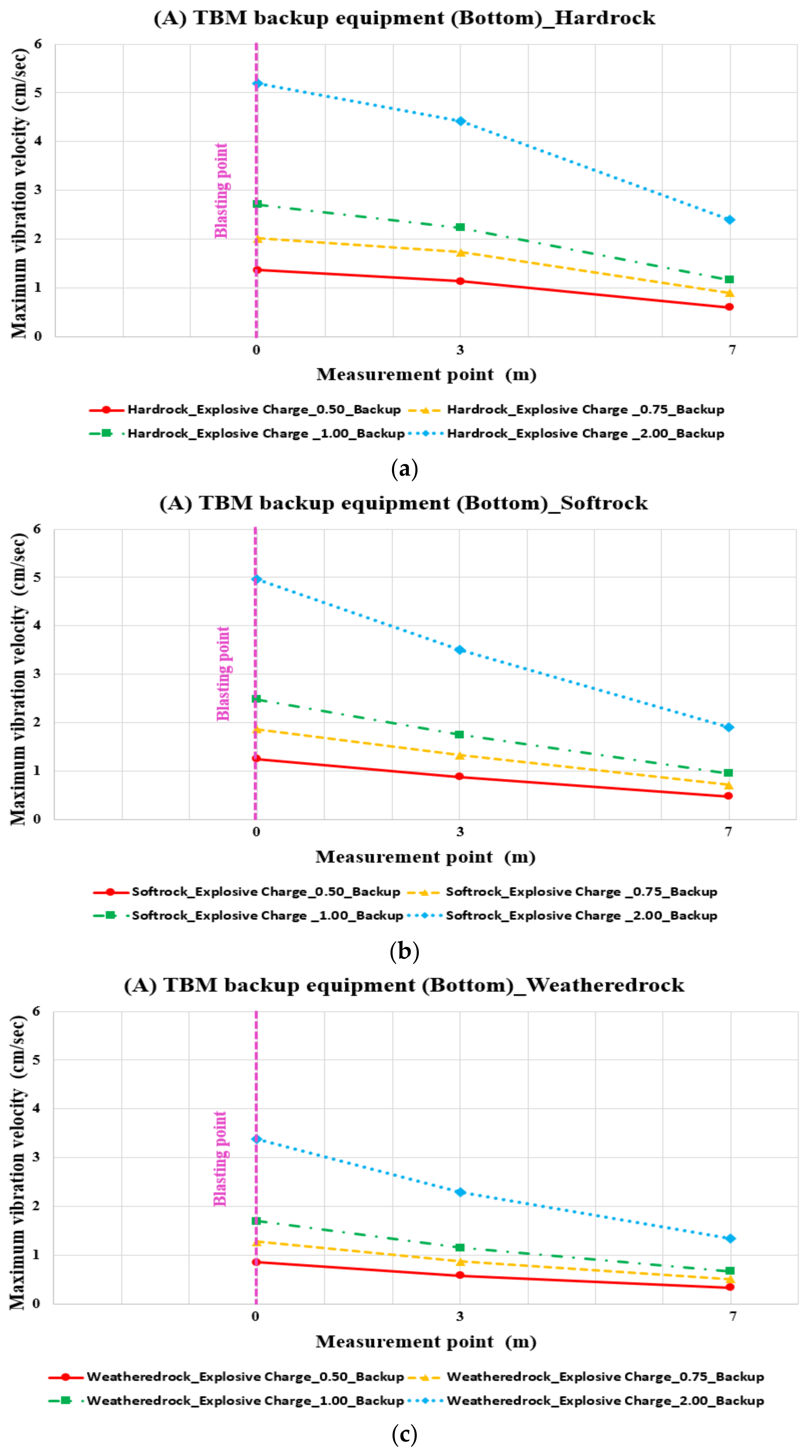
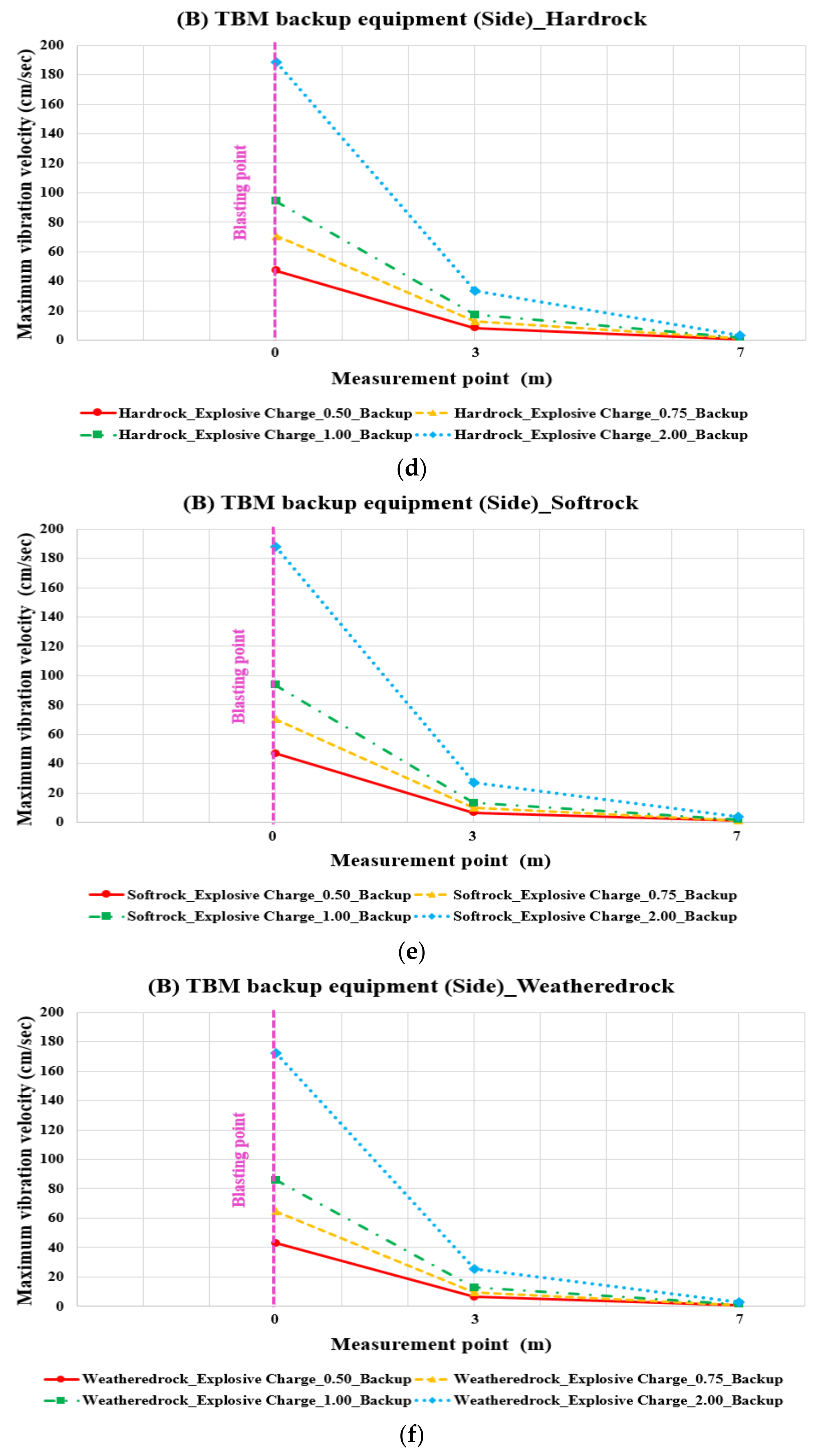
4.1. Effects of Blasting Vibration on the TBM Backup Unit Adjacent to the Blasting Point

Because the effects of blasting vibration are typically evaluated according to the vibration velocity, the vibration velocities transmitted to the TBM backup device (bottom and side) adjacent to the blasting point were measured and compared according to rock type (hard rock, soft rock, and weathered rock) and powder factor (0.5, 0.75, 1.0, and 2.0 kg). In Figure 5, the red, yellow, green, and blue lines represent the vibration velocities at powder factors of 0.5, 0.75, 1.0, and 2.0 kg, respectively. These vibration velocities decrease with distance from the blasting point in all rock types. Specifically, the vibration velocity at the bottom point gradually decreases with increasing distance. The vibration velocity at the sidewall exhibits a sharp decrease at a distance of 3 m (6-m point on the graph) from the blasting point (3-m point). This result can be assumed to be because the TBM and NATM parallel excavation method performs blasting on the contour hole without a center-cut blasting hole, so the blasting vibration is transmitted to the sidewalls closer to the contour hole. The vibration velocity was observed to be the highest in hard rock, followed by soft rock, and weathered rock, indicating better vibration transmission in denser rock. Compared to the domestic standards for permissible blasting vibration, the vibration velocity at the sidewall is lower than the regulated value only when a distance of at least 7 m (10-m point on the graph) is maintained from the blasting point, regardless of the rock type and powder factor. At the bottom, the vibrations in the hard and soft rocks were measured to be lower than the regulated level at a distance of at least 3 m from the blasting point [13]. Therefore, depending on the selection of the powder factor according to rock type, the separation distance (economic efficiency) can vary significantly.

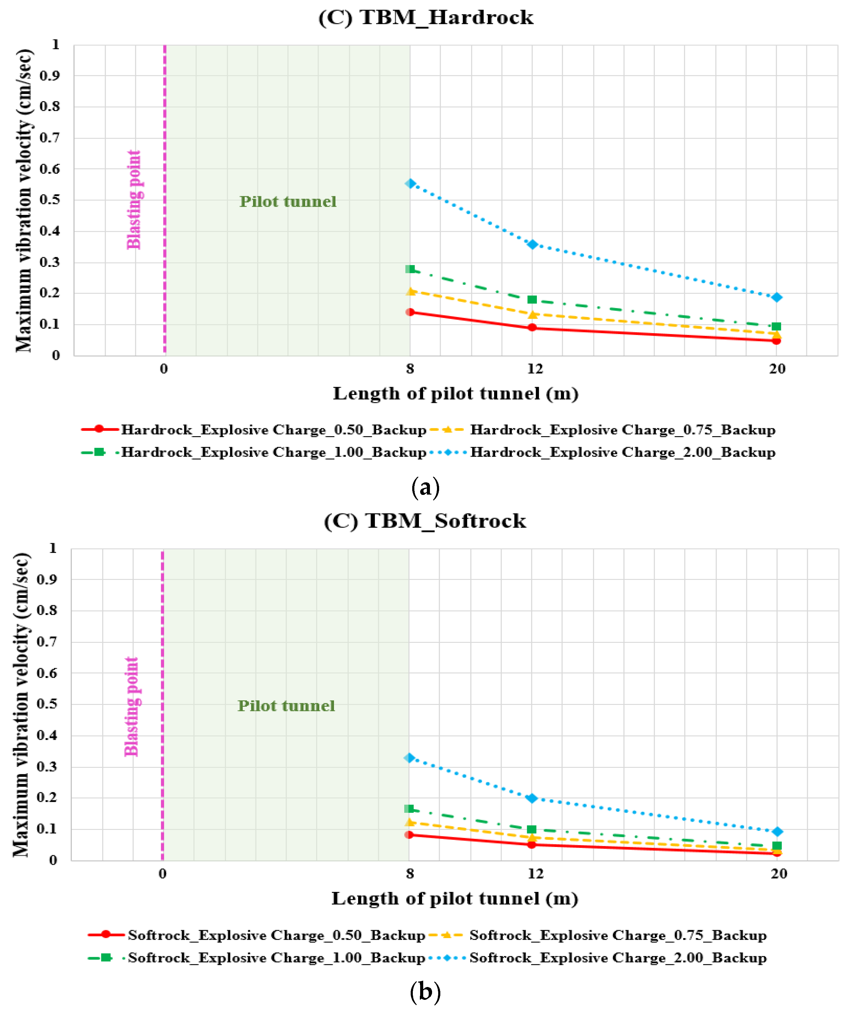
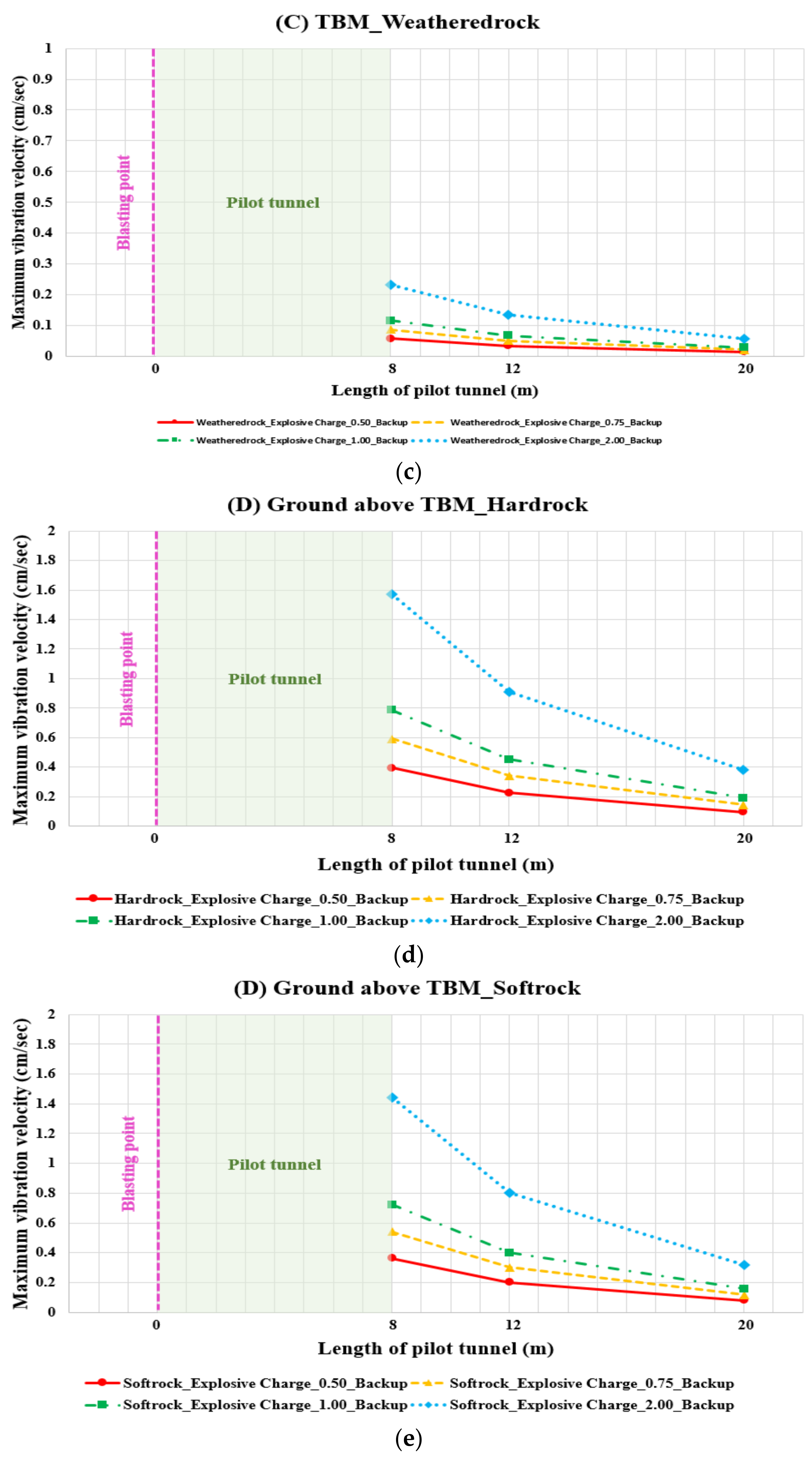
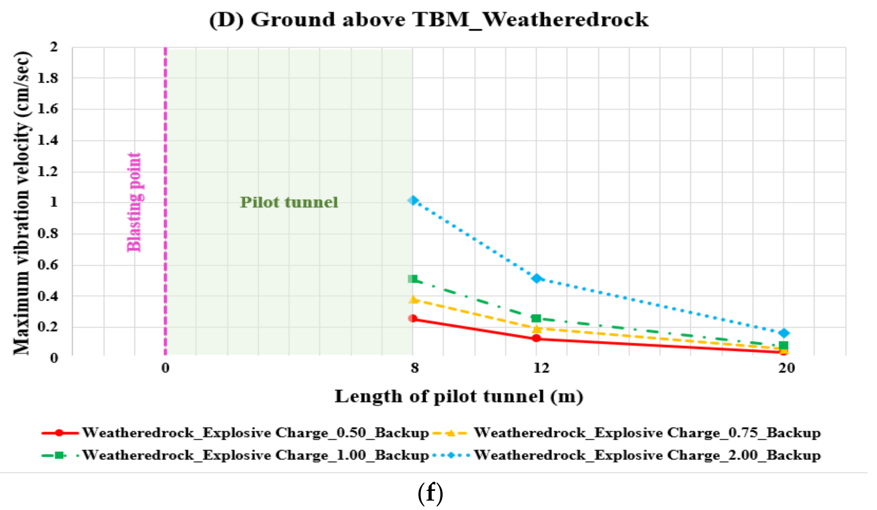
4.2. Effects of Blasting Vibration on the TBM and Ground above the TBM

Jamming caused by a problem in the TBM or a collapse of the ground above the TBM caused by NATM extended blasting may lead to a significant loss. Numerical analysis has been used to simulate the effects of blasting vibration on a TBM and ground above the TBM to prevent such incidents from occurring. Figure 6 illustrates the effects of blasting vibration on the TBM when the pilot tunnel length is 8 m (11-m point on the graph). The resultant values are lower than those permitted in the Seoul subway in all cases, except when a powder factor of 2.0 kg is applied to hard rock [14]. When the length of the pilot tunnel is 12 m (15-m point on the graph), the measured values are lower than the domestic vibration regulation standards (Seoul Subway Cultural Heritage, Vibration Regulation Standards for Buildings with Precision Machinery), regardless of the rock type and powder factor, which indicates that it is safe to maintain a separation distance of 16 m or more. The results are also lower than the national vibration regulation standards when the powder factor is 1.0 kg or less or when the rock layer is weathered.
The effects of blasting vibration transmitted to the ground above the TBM, regardless of the rock type, are greater than the regulated value for shopping complexes, offices, and public buildings when the powder factor is 2.0 kg or more. When the powder factor is 0.75 kg or less or when the length of the pilot tunnel is extended to 12 m, the vibration values are lower than the regulation value applicable to houses and apartments. Therefore, the length of the pilot tunnel can be reduced by selecting an appropriate rock type and power factor, which is expected to reduce construction time.

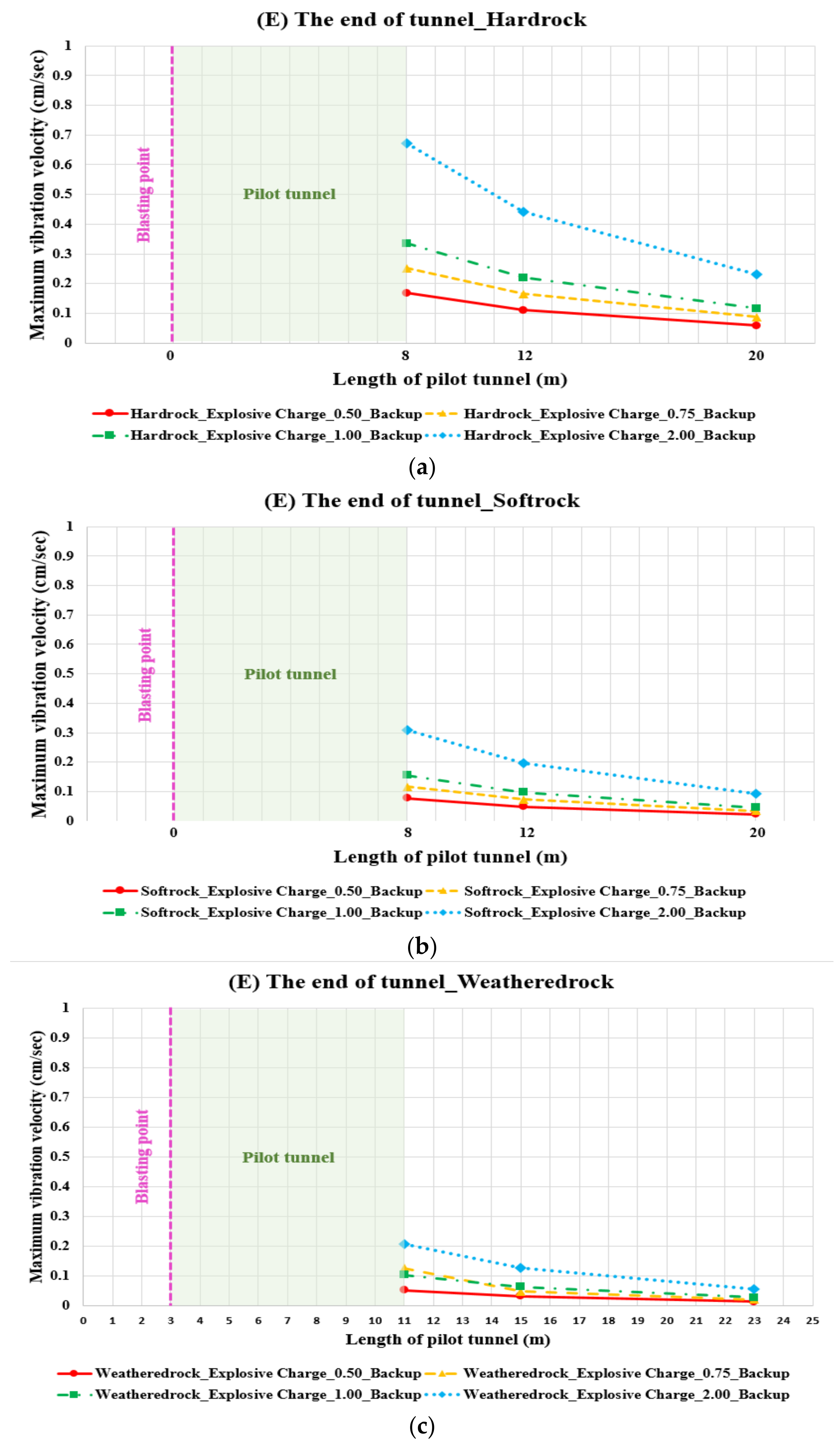
4.3. Effects of Blasting Vibration on the Tunnel Face and Ground Surface

Through numerical analysis, this study aimed to predict the effects of blasting vibration caused by NATM extending blasting on a TBM and TBM backup device and estimate an appropriate powder factor based on rock type and length of the pilot tunnel (separation distance between the blasting point and TBM). Furthermore, the vibrations transmitted to the tunnel face and ground surface were measured to ensure that no damage to the ground structure occurred and that no casualties occurred. Figure 7 presents the vibration velocities transmitted to the tunnel face and ground surface. The vibration velocities transmitted to the tunnel face and ground surface are lower than the regulated permissible vibration values (Seoul subway, house, and apartment vibration regulation values) in all cases, except for the case of hard rock with a powder factor of 2.0 kg or more. Consequently, it is determined that blasting vibration will not significantly affect the ground surface or superstructures.

5. Conclusions

Through numerical analysis, the effects of blasting vibration on a TBM and its backup unit during TBM pilot and NATM extending parallel excavation were assessed according to rock type and powder factor, and the necessary length of the pilot tunnel was determined. Furthermore, the vibration speed transmitted to the tunnel face and ground surface was measured to determine its impact on the surrounding ground and structures. The main findings of this study and prospects for future research are summarized as follows.
  • Depending on the type of rock and powder factor, the transmitted vibration velocity differs significantly. The measured vibration velocity increased with denser rock or higher powder factor. Based on the characteristics of blasting using a TBM and the NATM in parallel, which only blasts a contour hole without center-cut blasting, the effects of blasting vibration were greater on the sidewalls than on the bottom of the TBM backup device. In cases where the blasting point was separated from the sidewall by 7 m or more, or a distance of 3 m or more was secured to the bottom point, the vibration values were measured to be lower than the regulated values for large RC buildings. Therefore, it was determined that the TBM backup device should have a minimum separation distance of 7 m to ensure safety. Otherwise, an appropriate protection device is required.
  • In our analysis of blasting vibration on the TBM, the results were lower than the permissible values for houses and apartments in the Seoul subway system, except for the case of hard rock with a powder factor of 2.0 kg. Regardless of the rock type, the effects of blasting vibration transmitted to the ground above the TBM were higher than the vibration regulation value applicable to shopping complexes, offices, and public buildings when the powder factor was 2.0 kg or more. The effect was lower than the vibration regulation value applicable to houses and apartments when the powder factor was 0.75 kg or less or when the length of the pilot tunnel was extended to 12 m. Consequently, in cases with aboveground sensitivities, the powder factor should be reduced for safer construction. An adjustment of the powder factor when the ground is solid will shorten the pilot tunnel and construction period, which is anticipated to be economically beneficial.
  • In all cases, except for hard rock with a load of 2.0 kg or more, the blasting vibration transmitted to the tunnel face and ground surface had lower vibration values than the regulated values for houses and apartments. Therefore, it is expected that the damage to the ground surface and structures would not be excessive.
  • This study was limited to a specific tunnel size. The size of the required tunnel varies according to the utilization of the underground space, and the effect of vibration is expected to vary according to the size of the TBM pilot tunnel. Therefore, in future studies, the interaction between various NATM and TBM pilot tunnel sizes should be studied. In addition, this study simulated only the minimal shell blasting caused by the pilot tunnel. Additional research will be conducted on the number of blast holes, spacing, and cross-sectional shape under various conditions.

Author Contributions

S.-M.K. drafted and performed the numerical analysis; A.-R.K. and Y.B. investigated and reviewed the physical properties necessary for the analysis; S.-I.C. and S.S. reviewed and analyzed the existing literature and relevant materials; S.-W.L. analyzed the research concept and design, guided the dissertation, and conducted the final review. All authors have read and agreed to the published version of the manuscript.

Funding

This research was supported by the Ministry of Land, Infrastructure, and Transport (Korea Agency for Infrastructure Technology Advancement) under the project “Development of High-Speed Tunneling Technology for Long Tunnels Using Protective Shields (Parallel Excavation with a TBM Pilot and NATM Widening) (22TBIP-C155615-03)”. We thank them for their support in this research.

Institutional Review Board Statement

Not applicable.

Informed Consent Statement

Not applicable.

Data Availability Statement

Not applicable.

Conflicts of Interest

The authors declare no conflict of interest.

References

  1. Chun, B.S.; Song, S.H.; An, J.W. Ground behaviuor and reinforcing method of NATM tunnel through deep weathered zone. J. Korean Geotech. Soc. 2007, 23, 87–95. [Google Scholar]
  2. Heo, J.; Kim, B.I.; Lee, J.D.; Kim, Y.G. 3D numerical study on the reinforcing effect of inclined system bolting in NATM tunnel. J. Korean Geotech. Soc. 2017, 33, 29–36. [Google Scholar]
  3. Jeon, Y.J.; Lee, C.J. A Study on the behavior of single piles to adjacent tunneling in stiff clay. J. Korean Geo-Environ. Soc. 2015, 16, 13–22. [Google Scholar] [CrossRef] [Green Version]
  4. Kim, K.Y.; Kim, J.J.; Ryu, H.W.; Rehman, H.; Jafri, T.; Yoo, H.K.; Ha, S.G. Estimation method for TBM cutterhead drive design based on full-scale tunneling tests for application in utility tunnels. Appl. Sci. 2020, 10, 5187. [Google Scholar] [CrossRef]
  5. Liu, C.; Peng, Z.; Pan, L.; Yang, Y.; Chen, W.; Jiang, H. Influence of tunnel boring machine (TBM) advance on adjacent tunnel during ultra-rapid underground pass (URUP) tunneling: A case study and numerical investigation. Appl. Sci. 2020, 10, 3746. [Google Scholar] [CrossRef]
  6. Kong, S.M.; Choi, S.I.; Shim, S.B.; Lee, H.N.; Oh, D.W.; Lee, S.W. Stability Evaluation of TBM Pilot Tunnels to Rear Blasting Using the Protection Shield. Appl. Sci. 2021, 11, 1759. [Google Scholar] [CrossRef]
  7. Jo, H.; Park, J.I.; Lee, K.H. A case study on the NATM tunnel excavation under the soft soil ground condition by back analysis method. J. Korean Tunn. Undergr. Space Assoc. 2000, 2, 71–81. [Google Scholar]
  8. Kim, Y.S.; Jeong, W.S.; Lee, S.Y.; Seok, T.R. The prediction for ground movement of urban NATM tunnels using the strain-softening model. J. Korean Tunn. Undergr. Space Assoc. 2006, 8, 21–30. [Google Scholar]
  9. Hajihassani, M.; Abdullah, S.S.; Asteris, P.G.; Armaghani, D.J. A gene expression programming model for predicting tunnel convergence. Appl. Sci. 2019, 9, 4650. [Google Scholar] [CrossRef] [Green Version]
  10. Vitali, O.P.M.; Celestino, T.B.; Bobet, A. Construction strategies for a NATM tunnel in São Paulo, Brazil, in residual soil. Undergr. Space KeAi 2021, 4, 1–18. [Google Scholar] [CrossRef]
  11. Sauer, G.; Lama, R.D. An application of New Austrian Tunneling Method in difficult built over areas in Frankfurt/Main Metro. Symp. Rock Mech. Tunn. Probl. 1973, 1, 79–92. [Google Scholar]
  12. Kim, H.J.; Moon, H.K.; Lee, Y.J. Insights into the New Austrian Tunnelling Method (NATM) Ⅱ. Geotech. Eng. Korean Geotech. Soc. 2010, 26, 45–51. [Google Scholar]
  13. MOLIT. Tunnel Standard Specification; Ministry of Land, Infrastructure, and Transport: Seoul, Korea, 1999; p. 1.
  14. MOLIT. Review of Blast Noise and Vibration Tolerance Standards; Ministry of Land, Infrastructure, and Transport: Seoul, Korea, 2002; pp. 9–29.
  15. Jung, H.S. Rock Mechanics for Civil Engineers; Saeron: Seoul, Korea, 2004; pp. 262–342. [Google Scholar]
  16. FEIS. Construction-Related Noise and Vibration Impacts. Access to the Region’s Core; FEIS: New York, NY, USA, 2008; pp. 5.7.1–5.7.10. [Google Scholar]
  17. Itasca Consulting Group Inc. FLAC3D6.0 Manual: Examples (An. Excerpt from FLAC3D Help); Itasca Consulting Group Inc.: St. Paul, MN, USA, 2017; pp. 39–52. [Google Scholar]
  18. Jeon, S.S.; Cho, B.S.; Kim, D.S.; Jang, Y.W. Evaluation of the Tunnel Stability Induced by Blast Loading. In Proceedings of the Korean Society of Civil Engineers 2006 Convention Conference and Civil Expo, Seoul, Korea, 25 May 2006; pp. 4306–4309. [Google Scholar]
  19. Oh, W.K. A Study on the Ground Reinforcement for Constructability of Tubular Roof Construction Method. Master’s Thesis, Hanyang University, Seoul, Korea, 2008; p. 45. [Google Scholar]
  20. Hino, K. Theory and Practice of Blasting; Nippon Kayaku Co., Ltd.: Tokyo, Japan, 1959. [Google Scholar]
  21. Starfield, A.M.; Pugliese, J.M. Compression waves generated in rock by cylindrical explosive charges: A comparison between a computer model and field measurements. Int. J. Rock Mech. Min. Sci. Geomech. Abstr. 1968, 5, 65–77. [Google Scholar] [CrossRef]
  22. Jeon, S.S.; Jang, Y.W.; Jung, D.H. Estimation of blasting distance satisfying allowable peak particle velocity—Analytical & Numerical analysis approach. J. KOSHAM 2007, 7, 39–46. [Google Scholar]
  23. Ahn, J.K.; Park, D.H.; Shin, Y.W.; Park, I.J. Generation of blast load time series under tunneling. J. Korean Tunn. Undergr. Space Assoc. 2014, 16, 51–61. [Google Scholar] [CrossRef]
Figure 1. Numerical analysis modeling of the ground and TBM.
Applsci 12 03473 g001
Figure 2. Setting of mesh for numerical analysis.
Applsci 12 03473 g002
Figure 3. (a) Tamping and (b) decoupling time history curves.
Applsci 12 03473 g003aApplsci 12 03473 g003b
Figure 4. Vibration velocity measurement points.
Applsci 12 03473 g004
Figure 5. Analysis results for vibration velocity according to rock type and powder factor (measurement points A and B): (a) bottom of the TBM backup (hard rock), (b) bottom of the TBM backup (soft rock), (c) bottom of the TBM backup (weathered rock), (d) side of the TBM backup (hard rock), (e) side of the TBM backup (soft rock), and (f) side of the TBM backup (weathered rock).
Applsci 12 03473 g005aApplsci 12 03473 g005b
Figure 6. Analysis results for vibration velocity according to rock type and powder factor (measurement points C and D): (a) TBM (hard rock), (b) TBM (soft rock), (c) TBM (weathered rock), (d) ground above TBM (hard rock), (e) ground above TBM (soft rock), and (f) ground above TBM (weathered rock).
Applsci 12 03473 g006aApplsci 12 03473 g006bApplsci 12 03473 g006c
Figure 7. Analysis results for vibration velocity according to type of rock and powder factor (measurement points E and F): (a) tunnel face (hard rock), (b) tunnel face (soft rock), (c) tunnel face (weathered rock), (d) ground surface (hard rock), (e) ground surface (soft rock), (f) ground surface (weathered rock).
Applsci 12 03473 g007aApplsci 12 03473 g007b
Table 1. Examples of construction projects carried out in South Korea using the TBM and NATM extension blasting method.
Project NamePeriodTBM Size (m)Construction Length (m)
Cable Tunnel in
Pyeongtaek-si
June 2016–August 20172.9134
Jungnyeong TunnelApril 1997–20015.04122 × 2
New town bypass
in Haeundae
December 1992–19954.52200
Northern urban highway (Section 2)December 1991–December 19966.5/7.01783 × 2
Line 5 of Seoul Subway
(Sections 5–21)
December 1990–December 19933.5628 × 2
Table 2. Tunnel standard specifications for permissible blasting vibration [13].
Building TypePermissible Vibration (cm s−1)
Vibration-sensitive structures (cultural heritage)0.3
Structures with masonry infill walls and timber ceilings (traditional houses and low-rise general houses)1.0
Masonry buildings with underground foundations and concrete slabs (row houses)2.0
Medium and small buildings with reinforced concrete framework and slabs (low-rise apartments)3.0
Large buildings with reinforced concrete, reinforced framework, and slabs (high-rise apartments)5.0
Table 3. Blasting vibration standards for subway construction in Seoul and Busan [14].
ClassificationBuilding TypePermissible Vibration
(cm s−1)
Seoul subwayCultural heritage and buildings with precision machinery0.2
Houses and apartments0.5
Shopping complexes, offices, and public buildings1.0
Reinforced concrete and steel frame factories4.0
Busan subwayCultural heritage such as relics or ancient sites0.2
Nearby computer facilities0.2
Houses and apartments0.5
Shopping complexes1.0
Reinforced concrete buildings and factories1.0–4.0
Table 4. Overseas blasting vibration standards [15].
ClassificationBuilding TypePermissible
Vibration
(cm s−1)
United KingdomTunnel blasting in densely populated areas1.0
Tunnel blasting in areas with low population density2.5
Open-pit blasting at a frequency of 12 Hz or less1.2
Other0.5
United StatesVibration with a frequency of 40 Hz or more5.0
Vibration with a frequency of 15 Hz or more1.0
Vibration with a frequency of 1 Hz or less0.5
JapanNo damage caused0.2
Vibration can be detected, but no structural damage occurs0.2–0.5
Microscopic damage occurs only in areas where the structure is particularly vulnerable0.5–1.0
AustriaVibration with a frequency of 15 Hz or more1.9
Vibration with a frequency below 15 Hz0.02
SwitzerlandHistorical relics or sensitive structures at 10 to 60 Hz0.762
Historical relics or sensitive structures at 60 to 90 Hz1.27
Table 5. TBM vibration levels [16].
TBM TypeSoilPPV
Small
diameter
Bedrock0.03048 at 7.62 m0.0381 at 30.48 m0.0013462 at 60.96 m
Five-to-six meter diameterBedrock0.5588 at 4.88 m0.2286 at 10.06 m0.0762 at 20.12 m
0.0508 at 24.99 m0.0381 at 30.48 m0.013208 at 60.96 m
Glacial till/
dense sand
0.3048 at 4.88 m0.127 at 10.06 m0.0508 at 20.12 m
0.0254 at 24.99 m0.02032 at 30.48 m0.00762 at 60.96 m
Soft river
silt/clay
0.01016 at 10.06 m0.002032 at 20.17 m0.00254 at 24.99 m
0.002032 at 30.48 m0.000762 at 60.96 m
Table 6. Physical properties of the ground and TBM [17,18,19].
Title 1Modelγ (k N m3)E (k N m2)νc (k N m2)Φ‘ (°)
Weathered RockM-C2070,0000.32536
Soft rockM-C23250,0000.214032
Hard rockM-C2712,900,0000.2189040
TBMElastic78.520,000,0000.2--
γ: Unit weight of soil; E: Young’s modulus; ν: Poisson’s ratio; c: Cohesion; Φ‘: Angle of shearing resistance.
Table 7. Numerical analysis case classification.
Variable①:
Pilot Tunnel Length (m)
4816
Variable②:
Rock Condition
Weathered RockSoft rock Hard rock
Variable③:
Powder Factor (kg)
0.50.751.02.0
Table 8. Numerical analysis case classification.
Measurement PointPosition
ATBM backup equipment (bottom)
BTBM backup equipment (side)
CRear of TBM
DGround above the TBM
ETBM tunnel face
FGround surface
Publisher’s Note: MDPI stays neutral with regard to jurisdictional claims in published maps and institutional affiliations.

