1. Introduction
Although the concept of a steel special moment frame (SMF) is a relatively recent development in building codes, steel moment frames have been in use for more than one hundred years and date to the earliest use of structural steel in building construction [
1].
Over time, the design and construction methods for these steel structures have experienced a constant update aimed at meeting the needs and challenges generated by new construction projects [
2,
3]. In this context, building codes, such as AISC 358-16 and AISC 341-16 [
4,
5], have adopted a design philosophy intended to provide safety by avoiding earthquake-induced collapse in severe events. This approach permits extensive structural and nonstructural damage through a systematized and endorsed design and construction of a considerable variety of frames that adapt to a large number of civil steel constructions [
6].
At present, there is an increased demand for SMFs in civil construction due to their good dissipation response to seismic events and their versatility in architectural applications. These frames impose smaller forces on foundations when compared to other structural systems, making foundation systems more economical. Nonetheless, a design in compliance with seismic provisions must be guaranteed [
7,
8,
9,
10,
11,
12,
13,
14,
15,
16].
SMFs are composed of three basic elements: beams, columns and beam-column connections. Concrete-filled steel tubular (CFST) columns are widely used in architectural application proposals and in several industrial sectors due to their load carrying capacity under various loading conditions [
17].
Connections with diaphragms are also usually used in SMFs to guarantee structural integrity [
18,
19]. In this context, regulations such as AISC 358 present several prequalified connections. However, if a connection is not prequalified, it requires project-specific testing and must pass the criteria specified in AISC 341 [
5], which defines the recommended seismic design criteria for SMF buildings, including connections with external diaphragms. Nonetheless, although connections with external diaphragms are widely used, the current regulations impose strong limitations in their design guidelines. In addition, it is necessary to address some issues and explore the influence of various design parameters.
Experimental work has been conducted on different configurations of CFST column to steel beam connections to analyze their seismic behavior. For instance, Schneider, S. P. and Alostaz, Y. M. [
12] conducted tests for six different types of circular CFST welded connections utilizing the quasi-static test method. The connections were fabricated by utilizing different elements such as diaphragms, plates, embedded weldable deformed bars, continuous flanges, and continuous through steel tubes. In this work, the connections were tested to failure. The results indicated that welding the connection-stub directly to the skin of the steel tube resulted in a large deformation demand on the tube wall. In addition, they found that large tube wall distortions made the beam flange, the flange weld, and the tube wall highly susceptible to fracture. Therefore, none of these connections qualified to be utilized in systems with special energy dissipation capacity.
Cheng, C.T. and Chung, L. [
10] performed testing under cyclic loading on five circular CFST welded connections. They tested four types of joints characterized by the arrangement of weld from beam flange to the external diaphragm and by the tube walls of columns. The results showed that all the connections failed due to welding fracture during nonlinear behavior. According to the authors, the residual stress in the tube wall for this connection built up as a result of the welding of the diaphragm, causing a remarkable reduction in the deformation capacity of the column.
Shin et al. [
14] performed testing under cyclic loads on concrete filled tubular (CFT) column to H-beam welded moment connections with external T-stiffeners. They analyzed the strength ratio of the horizontal stiffener to the beam flange and the strength ratio of the vertical stiffener to the beam flange. Three types of failure modes were obtained: horizontal stiffeners failure, vertical stiffener failure, and beam failure. Their results showed that the connections reinforced with T-stiffeners having 130% of strength to beam flanges presented stable hysteretic behavior and good ductility.
Wu et al. [
20] conducted a series of cycling load tests for a proposed new design of bolted beam-to-column connections for CFT. In their design, the beam-to-column connection was of bolted type. Their results showed that bolted connections had superior seismic resistance in stiffness, strength, ductility, and energy dissipation mechanisms. They also showed that although the story angular drift reached 7%, the structure still stood with all the connections presenting plastic angular displacements of more than 5%, thus, meeting the specifications for seismic resistance.
Li et al. [
21] proposed and analyzed the seismic behavior of a connection for circular CFST column-to-steel beam composite structures. The connection was characterized by an extended endplate welded to a steel beam and bolted to a CFT column using high-strength steel rods. The experimental results indicated that the presence of floor slabs contributed to the strength of joints significantly and reduced beam sections were effective in moving the buckling zone away from the welds. More importantly, the connection exhibited good ductility and energy-dissipation capability, meeting the requirements recommended by AISC.
Sheet et al. [
13] tested four different connections with steel beams and CFT columns, under cyclic displacement-controlled load. Square and circular steel tubular columns were considered with two different types of connections: (i) shop welded, flat and curved extended endplates bolted to the CFT column with steel rods passing through the column, and (ii) a through beam connection type, where the beam passes through the joint and is connected with an additional bolted bracket without using any welding between the beam and the column. The experiments demonstrated that all the subassemblies performed in a ductile manner to large displacements with no apparent signs of local distress in the tube wall.
Tao et al. [
17] investigated the cyclic behavior of composite joints consisting of (CFST) columns, steel beams, and through-bolt connections. A total of ten specimens, including five specimens with square CFST columns and five specimens with circular CFST columns, were tested under lateral cyclic loading with horizontal displacements imposed at the top of the column. The hysteretic curves of the connections indicated very good energy absorption capacity, showing the potential to be used in earthquake-prone regions.
Mou, B. and Bai, Y. [
22] conducted research on the seismic behavior of novel steel-concrete composite beam-to-column connections reinforced by outer-annular-stiffener. This type of connection consisted of beams with varying depths in opposite sides, and a CFST column. Four cruciform connection specimens with varying beam depth ratios were tested under monotonic and cyclic loading protocols to investigate shear capacity, hysteretic behavior, deformation capacity and failure modes within the irregular joint panel zone. All the tested specimens demonstrated good plastic deformation and energy dissipation capacity.
Xu et al. [
23] evaluated the seismic performance of a damaged tolerant steel frame. In this steel frame, a composite ultra-high-performance concrete (UHPC) joint and friction damper were applied at the beam-to-column connection. The results showed that the UHPC joint provided excellent crack resistance and deformation capacity, while the friction damper resisted the moment in normal service and dissipated energy under earthquake conditions.
Hu et al. [
24] conducted experimental tests to evaluate the seismic performance of concrete-filled double-skin steel tube (CFDST)-steel beam frames with different construction details. The authors concluded that the CFDST structures exhibit better seismic performance, fire and corrosion resistances by comparing with the CFST structures. However, the application of the CFDST structures is much less common than the CFST structures due to the traditional construction processes of the CFDST structures, which are complicated and tedious.
Wang et al. [
25] conducted experiments to investigate the ultimate strength, deformation capacity and failure modes of a new irregular connection with reinforced concrete (RC) wing-walls. The hysteresis behavior of the connection was tested subjected to cyclic load with constant axial force. It was concluded that reinforced concrete wing-walls enabled the enhanced ductility and safety margin of the hybrid beam-to-column connections.
Wu et al. [
26] studied the seismic performance of a steel-reinforced concrete column-steel beam composite joint (MPCJ). They analyzed three different beam-column connection types: bolted, welded, and bolted-welded. The connections were subjected to low-cycle reversed loading to investigate the elastic and elastoplastic development trends, failure characteristics, and seismic response. The results showed bending failure at the end of the beam that follows the buckling of the flange connecting plate. This, while exhibiting stable hysteretic curves, also had reasonable strength and stiffness degradation, as well as good ductility and energy dissipation performance.
Rong et al. [
27] investigated the seismic performance of a steel frame with an external diaphragm joint between a CFST column and H-shaped steel beam. A quasistatic test was conducted to analyze the joint stiffness, beam-to-column stiffness ratio and concrete strength. Failure mode, lateral load versus displacement hysteretic curve, skeleton curve, strength and stiffness degradation effects, ductility, and energy dissipation capacity were analyzed. The experimental results showed hysteretic curves with a plump shuttle shape. In addition, the strength degradation effect and stiffness degradation effect were relatively feeble, and the ductility and energy dissipation capacity was excellent.
Mou et al. [
28] conducted experimental investigation on the seismic behavior of a novel connection between a beam and a reinforced concrete-filled steel tube (RCFST) column. The connection was tested under cyclic loading to evaluate the failure modes, hysteretic performance, stiffness degradation, strength degradation, energy dissipation capacity and the strain responses. The hysteretic curves showed obvious pinch phenomena because of the slip around the transfer sleeve which was identified as the key factor to affect the strength of the connection.
Li et al. [
29] studied a novel U-shaped diaphragm connection designed to transfer the moment at beam ends in the frame with special-shaped CFST columns and steel beams. The connection was tested under low-cycle horizontal loading. Based on the experimental results, the strength, ductility, and strain distribution of the connections were calculated. The results showed that this connection can develop plastic bending capacity in the beam, satisfying the design code requirements of America, Great Britain, and China.
The aforementioned research highlights the need to explore different types of connections in order to meet earthquake-resistant criteria while improving manufacturing processes; in this way, expanding the catalog of connections to be used depending on the different construction and architectural design requirements.
Despite all the work done so far, the steel beam-to-concrete-filled steel tubular column connection using external diaphragms represents a significant contribution to the state of the art since this connection has not been previously studied, despite its simplicity in the design and multiple constructive advantages. Thus, research aimed at a better understanding of the behavior of this type of connection is required. In this context, this article presents the experimental results of a steel beam-to-concrete-filled steel tubular column connection with external diaphragms and an analysis of its inelastic behavior due to cyclic loads according to the respective normative.
2. Materials and Methods
2.1. Research Framework
Despite of the multiple advantages observed for manufacturing and assembly, the steel beam-to-CFST column connection using external diaphragms is not covered within the AISC 358-16 standard [
4], which makes experimental studies under cyclic loads necessary. The hypothesis of this work is that following the design principles of AISC 341, AISC 358, and AISC 360, it is possible to obtain a connection suitable to be used in SMFs located in areas of high seismic threat. The methodology to verify this hypothesis includes design principles, testing and the verification of conditions to be approved for seismic resistance. The testing procedure is performed in accordance with FEMA 350 [
3].
Figure 1 illustrates the methodology framework followed in this work.
2.2. Design Procedure and Geometry of the Connection
To guarantee ductility in SMFs, design by capacity must be considered, which requires preparing the column and the elements that are part of the connection to resist the maximum forces that the steel beam can develop when entering the inelastic range. In addition, the damage must be concentrated at a specific location called the plastic hinge [
4].
Analytical and experimental considerations indicate that an excellent structural response can be achieved if the formation of a strong column-weak beam mechanism is induced through the design. In this mechanism, plastic hinges at the ends of the beams avoid excessive local ductility while the columns remain in the elastic range with the exception of the base of the columns. Additionally, the columns are subjected to variable axial loads due to seismic effects, which affects their resistance and ductility. In addition, the failure of a column can cause partial or total collapse of the building. These are the main reasons why the columns of the SMF are protected, which is based on the condition that they remain in the elastic range. To achieve this objective, it is of fundamental importance to apply the concepts of capacity design. In this way, a ductile response will be obtained in which the plasticization of the beams occurs progressively, and the system is capable of developing an adequate response [
1,
4,
30,
31]. In addition, the column and beam selection for the frame must comply with the seismic requirements of AISC 341-16, section E3 [
5], which provides the specifications for SMF with special energy dissipation capacity.
The analyses performed in this work allowed us to show that a strong column-weak beam relationship is guaranteed and that the plasticization mechanism is verified according to AISC 358 [
4]. In this work, the value of the moment ratio defined in AISC 341 which quantifies the column to beam strength ratio was equal to 1.26. This value was based on the actual materials strengths and was calculated by considering the actual expected maximum strength of the beam and the summation of the maximum probable moments. In addition, the design of bolts, external diaphragms, welding and connection to shear stresses were also guaranteed according to AISC 358, AISC 360 and AWS D1.1 [
4,
6,
32].
To comply with the above, several conditions were met in the design stage. These conditions are described as follows:
(1) The transverse section of the beam and the column must comply with the width-thickness relationship required to be classified as seismically compact. Likewise, it must be ensured that the beam skids are located laterally to avoid loss of capacity due to torsional lateral buckling.
(2) The strong column-weak beam hierarchy must be fulfilled, which is greater than unity. In addition, the sum of the probable moments in the beams and columns must be calculated from the centerline of the column and must consider the shear force located at the plastic hinge.
(3) The diameter and number of bolts must be obtained by considering the state of shear and crushing stresses in the diaphragm and the beam. The maximum bolt diameter,
, needed to control brittle failure in the beam flange, is determined by the following expression in millimeters [
4]:
where
is the dimension of the flange of the beam;
is the overstress factor, which depends on the material of the beam;
is the creep resistance; and
is the ratio of the expected tensile strength to the specific minimum tensile strength
.
The magnitude of the shear force
V to which the group of bolts is subjected must also be considered. This force must include the factor
and the maximum probable moment of the beam at the face of the column
, which is calculated as follows [
4]:
where
is the plastic module of the beam section;
is the shear force at the plastic hinge; and
is the location of the plastic hinge measured from the center of the column. The factor
, which is provided by AISC 358, considers the maximum probable resistance in the connection, including the effect of hardening by deformation of the material, and is calculated as follows [
4]:
In addition to the previous requirements, the bolts must be pretensioned to at least 70% of .
(4) The geometry of the diaphragm must be defined as a function of the diameter of the column. More precisely, the external diameter of the diaphragm must be equal to 1.5 times the diameter of the column and the tangent length must be equal to 25% of the diameter of the column . These dimensions were evaluated by means of numerical modeling, considering even the influence of the angle θ on the flow of efforts and levels of plastic deformation in the diaphragm. As a result, a value of 30 degrees was established for θ.
(5) The thickness of the diaphragm
must be obtained from the stress states of coarse area creep, net area fracture and shear block, considering the maximum capacity force,
. In turn,
is obtained by decomposing the maximum probable moment of the beam located on the face of the column between the web of the beam
and including the thickness of the diaphragm:
The thickness of the diaphragm must coincide with a commercial plate thickness. Thus, the iteration must be started with a preliminary thickness and its compliance with the mentioned stress states must be verified. For the resistance of the diaphragm, a resistance reduction factor for ductile limit state,
, must be considered according to AISC 358 [
4].
(6) Diaphragms must be connected to the column wall using full penetration welds. For this, it must be ensured that the edges are provided with 45-degree bevels. For this work, the AWS TC-U4b-GF type welding detail with preheating of parts according to AWS D1.1 was utilized [
32].
(7) Joining the shear plate to the column can be done using full penetration welds or fillet welds. If fillet welds are implemented, they must be calculated to resist the probable maximum shear .
Figure 2 shows the components and main dimensions of the connection obtained from the design process described above. The action of the maximum capacity force
and the maximum probable moment
are also illustrated. As shown in the figure, the column is made of ASTM A500 grade C steel and has a circular section with an outer diameter of 323.9 mm and a nominal wall thickness of 9 mm. The beam corresponds to an IPE360 rolled profile and is made of ASTM A572 grade 50 steel. The actual strengths of the steel were estimated according to the ASTM E8-11 standard [
33]. For the column, the values of 410 MPa and 563 MPa were obtained for the yield and ultimate limit of the material respectively, whereas for the beam, the corresponding values were 386 MPa and 540 MPa. The column was filled with concrete of 21 MPa compressive strength. The diaphragm thickness was 19 mm, and the number of bolts per diaphragm was 16 with a bolt diameter of 5/8 inches (15.875 mm) and made of ASTM A490 steel.
Table 1 shows all the relevant values of the connection.
2.3. Qualification Conditions
The SFM beam-column connection must satisfy the following conditions:
The bending capacity of the connection measured at the face of the column must be at least 0.8 , where is the plasticization moment of the beam calculated with the yield stress for the specified steel, with a floor distortion level of 0.04 rad.
The required shear strength of the connection must be determined from load combinations, including the amplified earthquake.
In special frame connections, critical demand welds must be considered along with the use of slots or full penetration welds.
2.4. Connection Assembly and Manufacturing Process
The manufacturing process of the full-scale prototype obeyed conventional processes for the manufacture of metal structures. The processes implemented were plasma cutting, inspection, polishing with hand tools, mechanized drilling, and welding with the semiautomatic MIG process. The following points are worth mentioning: the welds that join the diaphragm and the column were made with the full penetration MIG process, while the weld between the cutting plate and the column was a fillet weld; the diaphragm holes were made to a 1/16-inch (1.5875 mm) tolerance in diameter with the bolt; and the contact surfaces between the beam skids and the diaphragms were prepared to meet critical sliding contact and thus were not painted.
The test was carried out at the homologation framework lab (MaPH for its acronym in Spanish) located at the School of Civil Engineering of the University of Valle.
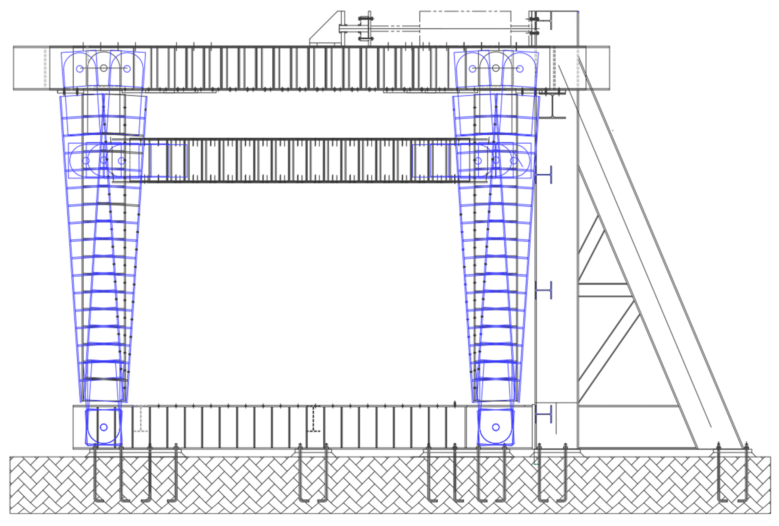
Figure 3 shows the experimental setup, including the mounting details of the beam–column connection. As shown in
Figure 3a, two supports were installed at each end of the column under the following constraint conditions: at end 1, translations in the plane and out of the plane were restricted; at end 2, vertical translation and translation outside the plane were also restricted; rotation in the plane was allowed for both ends.
Figure 3b illustrates the beams that provide lateral support to the framework.
The test specimen components were transported to the MaPH and assembled on site. Manually pretensioned bolted joints were utilized, thus providing a pre-tensioning force of 107 kN. In addition, direct tension indicator washers were utilized for the 5/8 in A490 bolts.
The MaPH has two auxiliary beams that provide lateral support to the IPE360 beam of the connection, which is located at a fixed distance: . This distance is greater than the maximum permissible length of the lateral support that guarantees the possibility of developing ductility: . Therefore, it was necessary to implement a geometry in the supports such that the distance was less than or equal to . In this case, the length of the beam measured from the axis of the column was ; the length of the column was and .
The test specimen was mounted on two supports that were installed at each end of the column. Support 1 is shown in
Figure 4a, and it was restricted for translations in the plane and out of the plane. The support 2 is shown in
Figure 4b. This support was restricted for vertical translation and out-of-plane translation. Rotation in the plane was allowed at both ends. The restriction of the translations was achieved by means of plates connected to the lower base of the MaPH, while rotation was allowed by means of a pin-type connection.
The test specimen was assembled in a T-shape, as shown in
Figure 3. In this configuration, the column was positioned horizontally and the beam vertically because the displacement system driven by the hydraulic actuator was located on top of the frame. The actuator allowed a maximum level of cyclic displacement of 270 mm. The deformed position of the frame at its maximum displacement during a displacement cycle can be observed in
Figure 5.
2.5. Displacement Protocol
Once the test specimen was assembled to the MaPH framework, the displacement protocol was programmed according to the procedure described in AISC 358 [
4]. This protocol corresponds to linear cyclic displacements divided into eleven discrete steps, which are shown in
Table 2.
Figure 6 shows the protocol applied for the test. The abscissa of the displacement protocol is presented in units of time in seconds, obtained as the quotient between the displacement ∆ and the loading application speed v. The displacement ∆ is equal to the angle of rotation multiplied by the length of the beam
. In this case
v = 1.49 mm/s and depends on the duration of the test, which was estimated at 6732 s to avoid high temperature increases in the hydraulic system.
The test allowed us to obtain the hysteresis curves, the mechanism of plasticization and the form of failure if such failure occurs. The hysteresis curves were obtained from the data acquisition system by utilizing the force and displacement vectors to further obtain the rotation and bending moment for each test load step. The hysteresis curves allowed us to identify the flexural capacity of the connection for a rotation of 0.04 rad and to compare its resistance against the minimum allowed according to the acceptance criteria.
The mechanism and form of failure are obtained visually. For this, three cameras were utilized, and they were located at the front, side and rear side of the setup. In addition, the surface of the connection was covered with a layer of lime, and a grid was drawn on those surfaces where the plastic joint was expected to appear.
4. Conclusions
Several of the connections utilized in SMF are not homologated under current design regulations. Therefore, studies are required to ensure that the designed frames dissipate their energy in the beams without affecting the connections. In this context, this paper presented an analysis of the inelastic behavior of a steel beam-to-concrete-filled steel tubular column connection using diaphragms.
During the experimentation, it was observed that the auxiliary beams showed deformations out of the plane due to their low rigidity. Thus, torsional lateral buckling occurred in the beam. Nonetheless, this occurred at a 0.07 rad of rotation for a moment resistant capacity of 453.9 kNm. Therefore, the hysteresis diagram did not show a significant loss of resistance due to this phenomenon.
Since the general behavior of the specimen until the displacement of 0.04 rad did not present a degradation in its resistance in terms of the load applied to the actuator, it was decided to continue with the protocol to the maximum allowed by the frame. That is, up to a rotation of 0.07 rad with increments of 0.01 rad for every two cycles. At this point, a local buckling occurred in one of the skates.
It was observed that at a rotation angle of 0.04, the flexural strength of the connection measured to the face of the column was 402.07 kNm. This value exceeded 1.4 times 80% of the plastic moment
(285.37 kNm). Thus, satisfying the requirement of AISC 358 for the qualification of connections belonging to porticos resistant to moments with special dissipation of energy [
4]. The maximum resistance moment achieved by the connection was 472.39 kNm at a rotation of 0.06 rad.
Regarding the pinching effect of the hysteresis curve due to crack nucleation of the concrete, it was determined that the specimen did not present an incursion into the inelastic range. Moreover, pinching due to bolt slip and to the sequence of yield and strength hardening does not prevent the connection from being utilized in an SMF with special energy dissipation capacity. Indeed, this effect is well known and has been documented for the qualification process of the bolted flange plate (BFP) moment connection covered by AISC 358-16 [
4].
For the plastic hinge , its location was 24% farther from the face of the column than initially assumed at the design stage.
The connection exhibited ductile hysteretic behavior with stable cycles and large areas of energy dissipation. It should be noted that the inclusion of the diaphragms contributed greatly to the beneficial behavior of the connection. This is achieved by transmitting the compression and tensile stresses generated by flexion while allowing adequate distribution over a large part of the periphery of the column. In addition, a positive effect was observed when filling the column with concrete because this decreased the possibility of the local buckling, as reported by Raychowdhury and Hutchinson [
34].


 and
and 


