Abstract
An active sound profiling (ASP) control algorithm based on the command FxLMS with an additive feedforward enhancement is suggested to overcome the limited performance to track a pre-defined target sound in a car cabin when an electronic sound generator (ESG) attached to a cowl panel of a car was adopted as a secondary actuator. As the uncertainty of the secondary path including the ESG-cowl pair was increased especially at higher frequencies, the tracking performance of a pure ASP algorithm was limited. The feedforward enhancement was added to the pure ASP algorithm to allow a robust tracking performance against a pre-defined target sound to enrich the insufficient engine sound at higher engine orders. After implementing this additive ASP approach in a test car, a real-time control experiment was carried out to demonstrate its tracking performance. A target sound was defined to cancel three engine order noises and to enhance the other three order sounds in the experiment. The experiment results showed that the proposed approach was able to provide an improved robust tracking performance at the engine orders for enhancing sound at higher frequencies compared to the pure ASP algorithm.
1. Introduction
For internal combustion engine vehicles (ICEV), active sound profiling (ASP) or active sound quality control (ASQC) approach has been used to improve engine sound quality in a cabin [1,2]. This ASP approach combines the active noise control (ANC) [3] for canceling engine booming noises of some engine orders and the active sound enrichment (ASE) [4] for enhancing insufficient engine sounds of other engine orders to satisfy the target levels.
In this study, an affordable vibration actuator and control system are considered to achieve better tracking performance of a target sound using an active control approach for passenger cars. By the way, a secondary path including such an actuator attached to a structural panel of a car showed an increased uncertainty due to its vibro-acoustic property over the frequency range of interest. This made the control performance restricted especially when such a vibration actuator on a structural panel is utilized under a pure ASP algorithm. In terms of canceling engine order noise at lower frequencies, the pure ASP algorithm can work properly even with such an actuator as the uncertainty in the secondary path is relatively small at the frequencies. However, the increased uncertainty at higher frequencies with such an actuator in the path restricts the application of the ASP control approach, especially in enhancing engine order sound. Thus, a new additive ASP approach is suggested in this study, which can provide better tracking performance by using an additional purely feedforward control.
As one of the algorithms for ASP, the narrowband active noise equalization (ANE) based on the filtered-x least mean square (FxLMS) was proposed by Kuo and Ji [5]. This algorithm can intentionally leave some residual noise or strengthen it as needed through a quality factor that can control the level of the noise selectively. If the algorithm is applied to engine sound control, the amplitude of each engine order can be adjusted uniformly regardless of engine speed. However, this algorithm would be unstable when the secondary path is significantly changed because it employs the internal model.
Rees and Elliott proposed an ASP algorithm known as the command-FxLMS, which provides more improved stability than the ANE algorithm [1]. The authors introduced a target sound, which is called the command signal, and modified the cost function to minimize the pseudo error, which is the difference between the error signal and the target sound. The command-FxLMS algorithm has been utilized for implementing ASP systems in a number of studies due to its simple structure and superior stability [6,7,8].
In the references of [6,7,8], the existing built-in door loudspeakers in their test cars were utilized as secondary actuators for the ASP implementation. However, the implementation of an ASP system using such loudspeakers in a car requires additional computational resources to run the algorithm under the real-time scheme. Since this can cause a cost burden for automakers to redesign the audio board and rewrite the software to commercialize the ASP system in their cars, a novel implementation of the ASP system that is independent of the existing audio board in a car can be considered by using an affordable approach.
Hence, in this study, an electronic sound generator (ESG) [9,10] and its dedicated control unit including a power amplifier were adopted for the ASP realization with a low cost. The ESG, which is composed of a voice-coil motor, was combined with a cowl panel of a car to generate a structure-borne sound as a secondary actuator, as can be seen from Figure 1.
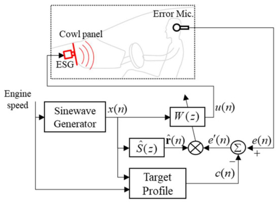
Figure 1.
Block diagram of the pure ASP control algorithm based on the command-FxLMS.
This kind of arrangement using a vibration actuator and a structure in a car was used to implement an ANC system for suppressing engine order noise in a study by Audrain [11], and it was also applied to realize an ASE system for enriching poor order sound independently from the ANC system [11]. However, very few attempts to use such an arrangement for an ASP system in a car have been made so far.
Therefore, this study focuses on utilizing the ESG-cowl pair as a secondary actuator to implement an ASP control system based on the command-FxLMS in a car. As mentioned at the beginning of this section, however, a secondary path of an ASP system using such an ESG-cowl pair has uncertainty increased with frequency, and this reduces the frequency range of the pure ASP control to enhance sound for maintaining stability. To overcome this limitation, an additive ASP algorithm with a purely feedforward enhancement is proposed, which can generate an additional enriching engine sound with robust stability even at the higher frequencies. The theoretical considerations of the additive ASP algorithm and the control filter design process of the feedforward enhancement are described in detail in the main body of this paper.
The ASP system with the proposed algorithm was implemented in an actual car, and the real-time control experiment was carried out for six engine orders when the engine of the test car was accelerated at the neutral mode. Then, the experiment result was analyzed and discussed in detail in terms of tracking performance by comparing the SPLs of each order before and after controls for the target SPL.
In this paper, theoretical considerations of the proposed ASP algorithm with the feedforward enhancement are investigated in Section 2. The experimental set-up for real-time ASP control is explained in Section 3. The analysis and discussions about the control experiment results are written in Section 4. The conclusions of this paper are summarized in Section 5.
2. Theoretical Considerations
2.1. ASP Control Algorithm
As illustrated in Figure 1, the block diagram of a ‘pure’ ASP algorithm using the command-FxLMS [1] can be applied to control the engine sound in a car cabin. The algorithm can offer both canceling engine order noise and enhancing engine order sound by minimizing the pseudo error signal as shown in Figure 1, which can be defined by
where , , , and are the error signal measured by a microphone located at the driver’s ear, the pre-defined target signal, the disturbance signal, and the output signal of the actual secondary actuator at the error microphone, respectively. The target signal is a sinusoid whose frequency is equal to that of the reference signal and its amplitude is the sound pressure level (SPL), which is stored in a pre-defined target profile based on the engine speed. Hence, when in Equation (1) is converged to zero, the error signal will track to the target signal . On the other hand, if is set to a tiny value, is approximately equal to , and then the ASP algorithm works to cancel engine order noise.
Thus, the instantaneous version of the cost function to be minimized in this ASP approach can be defined as [12,13]
where is a weighting parameter with a tiny positive number, which was introduced to obtain improved control stability during adaptation in practice, and is the coefficient vector of the adaptive control filter . The update equation to adapt the coefficient vector can be expressed as
where, is a convergence coefficient for adaptation and the derivative of the instantaneous cost function with respect to can be defined with , in which the filtered reference signal is the output of the secondary path model in the block diagram of Figure 1. After some manipulation, the adaptive update equation in Equation (3) for the pure narrowband ASP algorithm, which is based on the command FxLMS, can be rewritten by [1]
The leakage term , which is a positive number but less than 1, can suppress the divergence of the control filter output .
2.2. Limitation in the Usage of the ESG-Cowl Pair for ASP Control
In the usage of an ESG-cowl pair for the secondary actuator in the ASP control, the secondary path between the actuator and the error microphone is vulnerable to be exposed to an increased uncertainty especially when the temperature of the cowl panel of a car varies while driving. This is mainly caused by the nature of the vibro-acoustic property of a thin steel plate as its mechanical characteristics including the elastic modulus are dependent upon the temperature and, thus, its impulse response can be varied [14].
Hence, the actual secondary path using the ESG-cowl pair can be perturbed due to the uncertainty, and this can be expressed as [12]
where is the nominal secondary path and is the fractional change due to uncertainty [12]. Assuming the secondary path model is designed as , the error between the actual path and the path model can exist. The larger the temperature variation, the greater the uncertainty and error, especially at higher frequencies.
Such an increased error can affect the control performance and stability of the ASP algorithm. For noise canceling at lower engine orders, the ASP algorithm can work properly as the uncertainty in the secondary path is low such as C2. Thus, as plotted in Figure 2a, some booming noise at some engine speeds can be attenuated considerably although the achieved sound levels do not reach the target levels. However, for enhancing sound, the ASP algorithm may suffer from achieving the target levels when the engine orders are higher such as C9. As illustrated in Figure 2b, the amount of the gap between the target and the achieved levels can be very large at a higher engine speed range because the control logic is intentionally “off” to prevent from diverging of the ASP algorithm due to the increased uncertainty at higher frequencies.
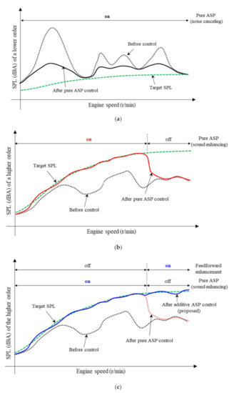
Figure 2.
Pure and additive ASP control schemes. (a) Noise canceling for a lower order and (b) sound enhancing for a higher order using the pure ASP algorithm. (c) Sound enhancing for the higher order using the proposed additive ASP algorithm with the feedforward enhancement.
Therefore, as depicted in Figure 2c, a noble additive ASP approach with a feedforward enhancement that can reduce the level gap by generating an additional enriching sound is proposed in Section 2.3.
2.3. Proposed Additive ASP Control Algorithm with a Feedforward Enhancement
Figure 3 shows the block diagram of the proposed additive ASP algorithm that consists of the pure ASP algorithm and the feedforward enhancement. The inside of the dashed box indicates the added feedforward enhancement. The subscripts noted as 1 and 2 in the symbols in Figure 3 mean the signals relevant to the pure ASP algorithm and the feedforward enhancement, respectively.
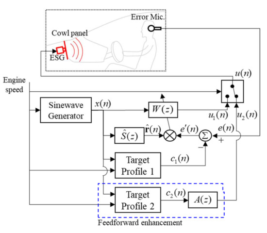
Figure 3.
Block diagram of the proposed additive ASP control algorithm with the feedforward enhancement.
As shown in Figure 3, these two sub-algorithms included in the additive ASP algorithm are operated in parallel, and they make their own control signal and , respectively. Then, the control signal , which is the output of the proposed algorithm is selectively switched to either or in accordance with the engine speed. This conversion is conducted at the switch block depicted in Figure 3. Thus, when the ASP control logic is “on”, the control signal is given by Equation (6a), but when the added feedforward enhancement is turned “on”, it is given by Equation (6b).
By the way, the feedforward enhancement in Figure 3 has a straightforward structure with a fixed control filter to compensate for the effect of the secondary path. This structure can be derived by simplifying a feedback ASP algorithm with the internal model control (IMC). The block diagram of the feedback algorithm is illustrated in Figure 4a, where is the estimate of the output signal of the secondary path model , which represents the internal model. The complementary sensitivity function of this feedback ASP algorithm can be given as [1,12]
where , and are the z-transforms of , and , respectively.
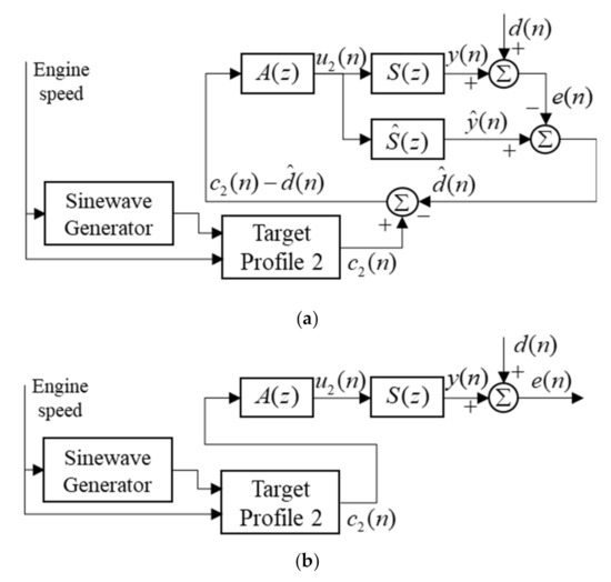
Figure 4.
(a) Feedback ASP algorithm with the IMC structure and (b) its simplified version as a purely feedforward form.
If and is ignorable as , then, Equation (7) can be rewritten by
Thus, from Equation (8), the feedback ASP algorithm illustrated in Figure 4a can be simplified as the purely feedforward form depicted in Figure 4b, and this is the feedforward enhancement in the proposed additive ASP algorithm in Figure 3.
If the control filter of the feedforward enhancement in Figure 4b is the perfect inverse of , will exactly follow . However, in practice, since using the ESG-cowl pair is a non-minimum phase, its stable perfect inverse cannot be obtained.
One possible approach to obtaining a realizable inverse filter of for is to use the Wiener filter design process [12] with a modeling delay [15]. This approach can offer a stable and causal FIR filter of by designing this as the delayed inverse of the secondary path , although makes track the target signal delayed by samples. The proper tracking performance of can be obtained with a suitable choice of .
By the way, from a practical point of view, it is required for sound enhancing to just augment the amplitude of to that of with regardless of the phase. This can also be achieved by compensating for just the magnitude response of instead of both magnitude and phase responses of . That means can be designed as the magnitude of , which can be given as
Such design of allows the effect of the modeling delays to be removed and makes act as an amplitude manipulator for .
3. Experimental Set-Up
3.1. Implementation of a Control System Using the ESG-Cowl Pair
A real-time control system was installed to assess the performances of the proposed additive ASP algorithm as well as the pure ASP algorithm in a 4-cylinder gasoline engine car. An ESG (See Table 1) was attached to the cowl panel of the test car to generate structural-acoustic sound. The cowl panel is a steel plate as a wall under the windshield between the engine room and the cabin. The additive ASP algorithm was implemented in a real-time control board (DS1041, dSPACE) and operated at a sampling frequency of 6400 Hz. A power amplifier (Stereo Box S, Pro-Ject) was used to operate the ESG. A microphone was installed at the drier’s left ear to measure the error signal and this signal was amplified by a signal conditioner (480E09, PCB). Two low-pass filters (cut-off frequency = 1000 Hz) were used either for anti-aliasing and reconstruction of the input and output signals of the control board. The engine speed was captured through the CAN using the OBDII port.

Table 1.
Specifications of the ESG.
3.2. Property of the Secondary Path Using the ESG-Cowl Pair
The two ASP algorithms can be operated on the same control system set-up using the ESG-cowl pair as explained in Section 3.1. The actual secondary path was defined as the electro-acoustic relationship between the input signal to the ESG and the output signal from the error microphone in the control board. The measured frequency responses below 850 Hz of at five different conditions of engine room temperature when the engine was off are plotted in Figure 5. As shown in the plot, it was observed that the change of engine room temperature affected the path to become perturbed rather easily especially at higher frequencies.
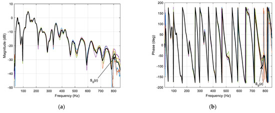
Figure 5.
Measured frequency responses of the secondary path using the ESG-cowl pair at five different temperature conditions. (a) Magnitude responses. (b) Phase responses.
This indicates that the secondary path using the ESG-cowl pair can be suffered from uncertainty at actual driving condition and this can restrict the control performance while maintaining proper control stability at higher frequencies.
The nominal secondary path was obtained by averaging the responses as plotted with a thick line in Figure 5. Then was used to design the path model , which was an FIR filter with the first 500 samples of the impulse response of as shown in Figure 6. The filter length was determined to accommodate the electro-acoustic property of the impulse response sufficiently. It must be considered that the computation requirement in the real-time control board is increased with a longer secondary path model.
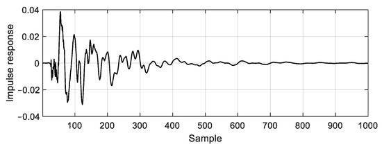
Figure 6.
Impulse response of the nominal secondary path .
In addition, the eigenvalue equalization approach [16] was applied to the design of the secondary path model. This approach can help achieve higher control performance by allowing a large gain while maintaining control stability. Hence, the convergence coefficient in Equation (4) was set to a constant value regardless of frequency.
By the way, the leakage term in Equation (4) was utilized to prevent the ASP control from becoming unstable at higher frequencies where were large. This term with a proper value can strongly suppress the control signal not having a huge value or not being diverged. Thus, the leakage term was scheduled with frequency, and its values from 690 Hz to 850 Hz with large were set to 0.98. This number was experimentally obtained. In addition, the leakage values at the frequencies, under 50 Hz and about 100, 215, 590 Hz, where the coherences of the nominal secondary path were less than 0.92 were also given by 0.98 for maintaining control stability. The leakage values at the other frequencies were set to 1. The scheduled leakage term was included in both the pure ASP algorithm and the additive ASP algorithm for updating their adaptive controller in the real-time control experiment and was applied to all orders to be controlled.
Incidentally, the two frequency groups divided according to the leakage values, 0.98 and 1, were utilized for the switching condition for Equations (6a) and (6b) in the suggested additive ASP algorithm.
4. Experiment Results and Analysis
Real-time control experiments using both the pure ASP algorithm in Figure 1 and the additive ASP algorithm with the feedforward enhancement in Figure 3 were carried out while the engine of the test car was accelerated from about 1000 r/min to about 5500 r/min at the neutral mode.
In the experiment, a total of six engine orders including three (C2, C4, and C8) for canceling noise and three (C3, C6, and C9) for enhancing sound were controlled against their pre-designed target profiles. The all-target levels of the C2, C4, and C8 orders were set to 0 dBA in the entire engine speed range because they were intended to be attenuated as much as possible. On the other hand, in the case of the other C3, C6 and C9 orders, specific target levels were given to them for enriching their sound.
The measured experiment results for each order using the pure ASP algorithm were analyzed in terms of noise reduction performance for noise canceling or tracking performance for sound enhancing. Then, the tracking performance of the proposed additive ASP algorithm was compared with that of the pure ASP algorithm. The design of for the feedforward enhancement was conducted before the additive ASP control experiment.
4.1. Control Performance Analysis of the Pure ASP Algorithm
4.1.1. Noise Reduction Performance for Noise Canceling
For comparison of the noise reduction performance of the three orders (C2, C4, and C8) for canceling order noise, the noise reduction between the measured error signal before and after controls can be defined as
where means frequency in r/min, is the A-weighted SPL of the measured error signal, and is that before control. This quantity indicates how much the SPL of the error signal is suppressed from that of before control, and it can be expressed in average over the engine speed range of 1000–5500 r/min for each engine order as . of the C2, C4, and C8 before and after controls are summarized in Table 2.

Table 2.
Summary of the noise reduction performance of the C2, C4, and C8 for canceling order noise using the pure ASP algorithm.
Figure 7 shows the comparisons of the SPLs of the C2, C4, and C8 before control (dotted lines) and after the pure ASP control (thin solid lines). Figure 7a,b displays the SPLs of the C2 before and after controls and the noise reduction defined in Equation (10), respectively. In addition, the leakage term used in the real-time control experiment for the C2 order was attached to the upper side of each figure. Figure 7c,d displays those of the C4 order, and Figure 7e,f plots those of the C8 order.
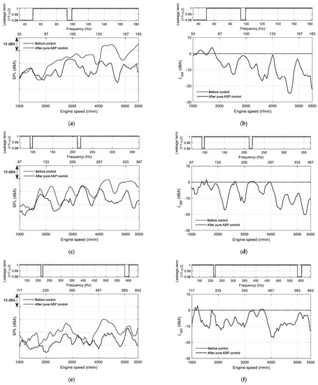
Figure 7.
Comparisons of the measured SPL of each order before and after the pure ASP control, and noise reductions. (a) SPL of the C2 order. (b) Noise reduction of the C2 order. (c) SPL of the C4 order. (d) Noise reduction of the C4 order. (e) SPL of the C8 order. (f) Noise reduction of the C8 order.
As can be seen from Figure 7, when the ASP control was applied, of the C2, C4, and C8 orders were attenuated dramatically over the almost entire engine speed range compared with those before control. Especially, in each order, at the largest booming noise was achieved by about −24, −20, and −17 dBA at about 4600, 4300, and 4200 r/min, respectively, and after control was obtained as −8.0, −6.8, and −6.6 dBA, respectively, as displayed in Table 2.
It is noteworthy that there were few changes in the SPLs before and after controls at some engine speed where the leakage value was 0.98. Nevertheless, due to the leakage term scheduled with frequency, the pure ASP algorithm maintained its stability robust over the entire engine speed range in the real-time control experiments.
4.1.2. Tracking Performance for Sound Enhancing
For comparison of the tracking performance of the C3, C6, and C9, the tracking error can be defined as the difference between the SPL of the measured error signal and the target SPL , and can be given as
indicates how closely the error signal tracks the target sound, so the closer it is to zero, the higher tracking performance is. The positive value of means the measured SPL of the error signal is larger than the target SPL, and the negative value implies the opposite. This can be expressed in root mean square (RMS) over the engine speed range of 1000–5500 r/min for each engine order as and those of the C3, C6, and C9 before and after controls summarized in Table 3.

Table 3.
Summary of the tracking performances of the pure and additive algorithms for the C3, C6, and C9 orders.
Figure 8 shows the comparisons of the tracking performances at the C3, C6, and C9 orders before control (dotted lines) and after the pure ASP control (thin solid lines) with the target profile (dashed lines). Figure 8a,b displays the SPLs of the C3 order before and after controls and the tracking error , respectively. Figure 8c,d show those of the C6 order, and Figure 8e,f denote those of the C9 order. In each figure, the leakage term for each order is included at the upper side.
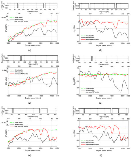
Figure 8.
Comparisons of the measured SPL of each order before and after the pure ASP control, and the tracking errors between the measured SPLs and the target profiles. (a) SPL of the C3 order. (b) Tracking error of the C3 order. (c) SPL of the C6 order. (d) Tracking error of the C6 order. (e) SPL of the C9 order. (f) Tracking error of the C9 order.
In the case of the C3 order, as illustrated in Figure 8a,b, the SPLs in particular above 2200 r/min after control were dramatically enhanced to track the target profile. Thus, was obtained by −10 to 3 dBA over the entire engine speed range, whereas before control was varied from −25 to 1 dBA. It is noteworthy that there was a sharp drop in of −10 dBA at 4300 r/min (215 Hz). This was because the control signal was suppressed by the leakage term, which was given as 0.98 due to insufficient coherence at this frequency. Nevertheless, after control was greatly improved by 2.9 dBA, which was 10.3 dBA less than that before control as shown in Table 3.
In the case of the C6 order, as can be seen from Figure 8c,d, the ASP control was activated at almost the entire engine speed range except for 215 Hz. The SPLs after control were followed the target profile very closely with of −4 to 3 dBA compared with that of −26 to 6 dBA before control. Thus, of the C6 order after control was achieved by 1.4 dBA, whereas that before control was 11.0 dBA as presented in Table 3.
In the case of the C9 order, as shown in Figure 8e,f, under 3800 r/min (570 Hz) were significantly improved from a range of −25 to 2 dBA to that of −4 to 2 dBA by the ASP control. However, it was observed that there was −10 dB of at around 4000 r/min (600 Hz) due to the leakage value of 0.98. Moreover, there was little difference in before and after controls above about 4800 r/min (690 Hz). This was because the ASP control was restricted using the leakage term to protect the control stability from the increased uncertainties at these higher frequencies. Thus, as displayed in Table 3, after control was obtained by 7.5 dBA, approximately half that before control, but that was about 4–6 dBA higher than that of the C3 and C6 orders.
4.2. Design of A(z) for the Feedforward Enhancement
As described in Section 2.3, of the feedforward enhancement in the additive ASP algorithm is defined as the magnitude of the delayed inverse of the nominal secondary path from Equation (9). Thus, in this study, at first, the optimal FIR filter of with length was obtained using the Wiener filter design process with the modeling delay approach. A number of computations were carried out to determine the optimal and , which minimize the mean square value of the modeling error. The filter length was varied from 1000 to 6000 samples with an interval of 1000 samples. In each , the mean square errors (MSEs) were calculated with various from 0 to 1.2 times of with 10 samples interval. Consequently, the optimal and , which provided the minimum MSE were attained by 4000 (See Figure 9a) and 1290 (See Figure 9b) samples, respectively. The optimally designed FIR filter coefficients, which is the impulse response, of is illustrated in Figure 10.
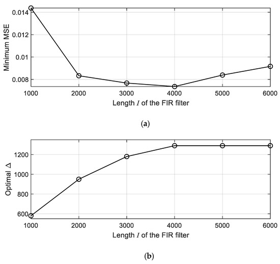
Figure 9.
(a) Minimum MSE with (b) the optimal ∆ at each length I of the FIR filter.
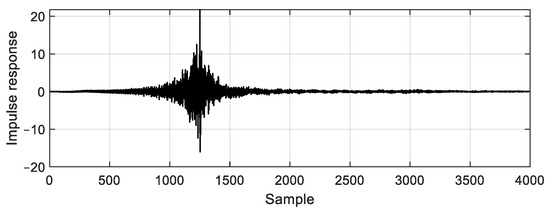
Figure 10.
Impulse response of .
Then, was obtained by taking the modulus of , which was attained by transforming the designed impulse response in the z-domain. Figure 11 shows the comparison of the magnitude responses of (a dashed line) and (a dotted line), which are transformed from the two impulse responses displayed in Figure 6 and Figure 10, respectively, and the magnitude of (a solid line) is also plotted in Figure 11 together. It was found that the magnitude response of was well-matched with that of at most frequency range since that of was almost 0 dB except for about 100 Hz.
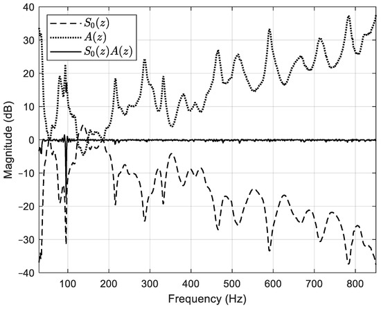
Figure 11.
Magnitude responses of (a dashed line), (a dotted line), and (a solid line).
The designed was implemented in the additive ASP algorithm using a lookup table.
4.3. Tracking Performance of the Proposed Additive ASP Algorithm
Figure 12 plots the results of the proposed additive ASP control experiment (thick solid lines) along with the results displayed in Figure 8, which shows the comparisons of the tracking performance of the pure and additive ASP algorithms for the C3, C6, and C9 orders.
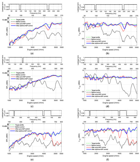
Figure 12.
Comparisons of the measured SPL of each order after the pure and additive ASP controls, and the tracking errors between the measured SPLs and the target profiles. (a) SPL of the C3 order. (b) Tracking error of the C3 order. (c) SPL of the C6 order. (d) Tracking error of the C6 order. (e) SPL of the C9 order. (f) Tracking error of the C9 order.
In the case of the C3 order, as can be seen from Figure 12a,b, there was no notable difference between the tracking errors after the two ASP controls in the engine speed range where the leakage value was 1. On the other hand, at the vicinity of 4300 r/min (215 Hz) where the leakage value was 0.98, a little betterment in tracking performance when the additive ASP control was applied was observed with −7 to 2 dBA of compared with −10 to 0 dBA after the pure ASP control. Such insufficient improvement appeared to be due to the fractional change at around 215 Hz included in the actual secondary path . The reason is that, during the control experiment, had a high possibility of having a large when considering the fact that there were the large at around 215 Hz in the perturbed frequency responses of the secondary path as shown in Figure 5. However, due to this improvement by the feedforward enhancement of the additive ASP algorithm, 1.8 dBA of was obtained. This value is 1.1 dBA less than that of the pure ASP control experiment result as displayed in Table 3.
In the case of the C6 order, as shown in Figure 12c,d, there was no meaningful difference between the SPLs after the two ASP controls because the feedforward enhancement was not activated at the nearly entire engine speed range with the exception of about 2150 r/min (215 Hz). However, even at this engine speed, there was nothing notable since the SPL of the target profile was almost the same as that before control. Thus, after the additive ASP control was 1.3 dBA, which was almost equal to that after the pure ASP control with just 0.1 dBA of difference as shown in Table 3.
In the case of the C9 order, as plotted in Figure 12e,f, the poor tracking performances of the pure ASP control were significantly improved when the additive ASP control was applied. The discontinuity of the SPL at 4000 r/min (600 Hz) existed in the pure ASP control experiment result was removed by achieving almost 0 dBA of through the feedforward enhancement. This feedforward enhancement also made the SPLs above 4600 r/min (690 Hz) track the target profile with about −5 to 5 dBA of . However, the range of this target error was broader than that under 4600 r/min, which was about −3 to 3 dBA; this was because of the increased included in the actual secondary path at the higher frequencies, as shown in Figure 5. Thus, after the additive ASP control was 1.7 dBA, which was about 5.8 dBA less than that after the pure ASP control as displayed in Table 3.
These results showed that the proposed additive ASP algorithm can provide the tracking control to enhance order sound continuously at higher frequencies where the pure ASP control is limited due to high uncertainties in the secondary path.
However, it was found that the tracking performance of the proposed algorithm could be degraded at some frequencies where was large. The degradation may be more distinctly observed as is more increased. Moreover, it is expected that the tracking performance can also be degraded if has a large value that cannot be negligible compared with that of . The degree of the tracking error depends on the amplitude and phase difference between the two signals.
5. Conclusions
This study suggests an additive ASP algorithm with the feedforward enhancement to overcome the poor tracking performance of the pure ASP control in a car cabin at higher frequencies due to the large uncertainty included in the secondary path using the ESG-cowl pair as a secondary actuator. Two real-time control experiments using the pure and additive ASP algorithms were carried out while the engine speed was swept at the neutral mode when the test car was stationary.
From the real-time control experiment results, the tracking performances, as the RMS of the target error , of the C3 and C9 orders after control using the additive ASP algorithm were achieved by 1.8 dBA and 1.7 dBA, respectively, which were better than 2.9 dBA and 7.5 dBA of the pure ASP control experiment results, as described in Table 3.
These results reveal that the additive ASP algorithm was effectively applied to the ASP system using the pair of the ESG and the cowl panel as a secondary actuator. This additive approach could also be adopted to ASP systems using other types of actuators, which makes the frequency range of the pure ASP control confined due to the uncertainty included in their secondary path.
The above ASP control experiment results were obtained at the neutral mode with the stationary test car. That means the primary noise was the engine sound only. However, in practice, road noise will also be involved in the primary noise when the car is driven on a road. Thus, the effect of the road noise on the performance and stability of the proposed algorithm will be investigated in future work.
Author Contributions
Data curation, Y.-S.L.; Software, J.L.; Validation, E.Y.; Writing—original draft, S.R.; Writing—review & editing, C.L. All authors have read and agreed to the published version of the manuscript.
Funding
This work was supported by the Incheon National University Research Grant in 2018.
Institutional Review Board Statement
Not applicable.
Informed Consent Statement
Not applicable.
Data Availability Statement
Not applicable.
Conflicts of Interest
The authors declare no conflict of interest.
References
- Rees, L.E.; Elliott, S.J. Adaptive algorithms for active sound-profiling. IEEE Trans. Audio Speech Lang. Process. 2006, 14, 711–719. [Google Scholar] [CrossRef]
- Kuo, S.M.; Gupta, A.; Mallu, S. Developtment of adaptive algorithm for active sound quality control. J. Sound Vib. 2007, 229, 12–21. [Google Scholar] [CrossRef]
- Elliott, S.J.; Stothers, I.M.; Nelson, P.A.; McDonald, A.M.; Quinn, D.C.; Saunders, T. The active control of engine noise inside cars. INTER-NOISE NOISE-CON Congr. Conf. Proc. 1998, 1998, 987–990. [Google Scholar]
- Schirmacher, R. Active Noise Control and Active Sound Design-Enabling Factors for New Powertrain Technologies; SAE Technical Paper 2010-01-1408; Society of Automonive Engineers (SAE): Warrendale, PA, USA, 2010. [Google Scholar]
- Kuo, S.M.; Ji, M.J. Development and analysis of an adaptive noise equalizer. IEEE Trans. Speech Audio Process. 1995, 3, 217–222. [Google Scholar] [CrossRef]
- Carme, C.; Mellin, V.; Kronast, M. Sound profiling for active noise control. INTER-NOISE NOISE-CON Congr. Conf. Proc. 2006, 2006, 600–607. [Google Scholar]
- Kataja, J. Development of a Robust and Computationally-Efficient Active Sound Profiling Algorithm in a Passenger Car. Licentiate Thesis, Tampere University of Technology, Espoo, Finland, 2012. [Google Scholar]
- Ryu, S.; Lee, Y.-S.; Kim, S. Active control of engine sound quality in a passenger Car using a virtual error microphone. Int. J. Parallel Program. 2019, 48, 909–927. [Google Scholar] [CrossRef]
- Kendrion. Sound Systems for Vehicle Interiors. Available online: https://www.kendrion.com/en/products/soundsystems/sound-systems-for-vehicle-interiors (accessed on 24 March 2022).
- Lee, Y.-S.; Ryu, S.; Yoo, E.; Lim, C. A feasibility study of an ESG to suppress road noise of a car. Appl. Sci. 2022, 12, 2697. [Google Scholar] [CrossRef]
- Audrain, P. Active Sound Design; SAE Technical Paper 2011-01-0927; Society of Automonive Engineers (SAE): Warrendale, PA, USA, 2011. [Google Scholar]
- Elliott, S.J. Signal Processing for Active Control; Academic Press: London, UK, 2001. [Google Scholar]
- Kuo, S.M.; Morgan, D.R. Active Noise Control Systems: Algorithms and DSP Implementations; John Wiley & Sons: New York, NY, USA, 1996. [Google Scholar]
- Fahy, F.; Gardonio, P. Sound and Structural Vibration, 2nd ed.; Academic Press: London, UK, 2007. [Google Scholar]
- Widrow, B.; Whlach, E. Adaptive Inverse Control; Prentice-Hall International Editions: London, UK, 1996. [Google Scholar]
- Thomas, J.K.; Lovstedt, S.P.; Blotter, J.D.; Sommerfeldt, S.D. Eigenvalue equalization filtered-x algorithm for the multi-channel active noise control of stationary and nonstationary signals. J. Acoust. Soc. Am. 2008, 123, 4238–4249. [Google Scholar] [CrossRef] [PubMed]
Publisher’s Note: MDPI stays neutral with regard to jurisdictional claims in published maps and institutional affiliations. |
© 2022 by the authors. Licensee MDPI, Basel, Switzerland. This article is an open access article distributed under the terms and conditions of the Creative Commons Attribution (CC BY) license (https://creativecommons.org/licenses/by/4.0/).