Article

Flexural Analysis Model of Externally Prestressed Steel-Concrete Composite Beam with Nonlinear Interfacial Connection

1
China Railway Economic and Planning Research Institute Co., Ltd., Beijing 100038, China
2
School of Civil Engineering, Beijing Jiaotong University, Beijing 100044, China
3
China Building Technique Group Co., Ltd., Beijing 100013, China
*
Author to whom correspondence should be addressed.
Appl. Sci. 2022, 12(9), 4699; https://doi.org/10.3390/app12094699
Submission received: 12 April 2022 / Revised: 4 May 2022 / Accepted: 5 May 2022 / Published: 7 May 2022
(This article belongs to the Section Civil Engineering)

Abstract

:
Interfacial slip effects and the unbonded phenomenon of external tendons are the key mechanical features of the externally prestressed steel-concrete composite beams (EPCBs). In this paper, an 8-node fiber beam element is built for the nonlinear analysis of the composite beam with interfacial slip effects. A multi-node slipping cable element is proposed for the simulation of external tendons. The derived formulations are programmed in OpenSees as newly developed element classes to be conveniently used for the flexural analysis of EPCBs. The effectiveness of the proposed model is fully verified against the experimental tests of simply supported and continuous beams and then applied to the parametric study. The results show that the increasing deviator spacing will significantly decrease the tendon effective depth at ultimate states and further decrease the flexural capacity. The larger effective depth is beneficial to the tendon stress increments and further improves the flexural capacity. The enhancement of interfacial shear connection degree will increase the structural capacity but the effects on the tendon stress increments and second-order effects were not monotonic.

1. Introduction

Steel-concrete composite beams are widely used in practice due to their efficient material usage and remarkable features: low self-weight, high ductility and rapid construction [1]. For the construction of longer span steel-concrete composite beams or in retrofitting, external prestressing is a commonly employed technology to improve structural performance [2]. The flexural capacity, deflections and stress level will be significantly reinforced in the externally prestressed composite beams (EPCBs).
Compared with conventional post-tensioned members, EPCB has two featured mechanical behaviors, including slip effects at the interface [3] and the unbonded phenomenon of external tendons [4,5,6]. Both of the actions are member-dependent behaviors rather than cross-section-dependent, increasing the complexity of structural analysis and design.
During recent decades, many experimental tests [7,8,9,10,11,12,13,14,15,16] have been conducted to investigate the structural behaviors of EPCBs. The test by Ayyub et al. [7] confirmed the improvement of external prestressing on the structural load carrying capacity and ductility. While they also concluded that the interfacial slip caused larger deflections than their analytical predictions with the no-slip assumption. Chen and Gu [8,9] finished two EPCB tests under positive moment loading and four groups of EPCB tests under hogging moment loading, pointing out that external tendons developed substantial incremental stress at the ultimate state. Lorenc and Kubica [10] tested six EPCBs with different tendon profiles. Chen et al. [11,12], Nie et al. [13] and Sun et al. [14] tested the effects of external prestressing in continuous EPCBs and revealed that both the tendon stress increments and interfacial slip effects affected the structural deformation and load-carrying capacity. Recently, more concerns were paid to EPCB designed with a partial shear connection [17,18] or existing structures with degraded interfacial shear resistance in particular [19]. The tests by Hassanin et al. [15] and El-Sisi et al. [16] showed that an increase in shear connection degree from 0.4 to 1.0 led to a 46% load capacity increment of an EPCB. The simultaneous effects of interfacial slip and the unbonded phenomenon of external tendons lead to more difficulties for flexural response predictions of EPCB. The numerical model was usually taken as the optional solution.
A reliable numerical model for EPCB should include the following considerations: the material and geometrical nonlinearities, the nonlinear interfacial connection, and the free-slip behaviors of external tendons at deviators. To date, there are mainly two kinds of numerical models presented in the references, the refined solid model and the beam-tendon model.
In the refined solid models, the steel beam, concrete slab, and even the shear connectors were all modeled by the shell or solid elements concerning actual geometrical shapes [20,21,22,23,24,25,26]. These models were usually directly modeled in common FE software. The interfacial shear-slip behaviors between the steel beams and concrete slabs were modeled by the contact element with cohesive or friction properties. But there were still no available element types in current 3D FE software for external tendons with free-slip behaviors at deviators. The conventional truss element [23,24,25] cannot satisfy the strain-compatible relation between the adjacent tendon segments. Meanwhile, the complex modeling process and enormous computational costs were usually needed in these models, reducing the analysis efficiency for large-scale structures.
In beam-tendon models, the composite beam and external tendons were all modeled by the one-dimensional structural element types, such as beam and link/truss elements. (1) For composite beam, Lou et al. [27,28,29,30] and El-Zohairy et al. [31] adopted the conventional fiber beam element to model the flexural behaviors. The interfacial slip effect was not considered as there was no interfacial slip defined for the conventional fiber beam element. To address this issue, Zhang et al. proposed a modified modeling method [32] in which the steel beam and concrete slab were separately modeled by beam elements and the non-linear spring elements were added between them to model the slip effect. This method was verified to be effective but needed a fussy modeling process to define the DOFs coupling relation. Dall’Asta [33,34,35] and Sousa et al. [36] proposed the idea of introducing additional DOFs into the Euler–Bernoulli beam element to consider interfacial slip effects. A three-node 10-DOF element, taking the axial deformation of steel beams and concrete slabs as the separate DOFs, was proposed for the composite beam with deformable connectors. This was a good idea and was followed by the authors. While a new thought of taking the interfacial relative slip deformation as the additional DOF was proposed in this paper, then the FE formulation was further simplified and a two-node 8 DOF element was built. (2) For the modeling of the external tendon, ignoring frictions between tendon and deviators, the traction was assumed to be equal along the whole length. With the strain-compatible relation considered, Lou et al. [28,29,30] proposed an equivalent loads method to model the unbonded effects of the external tendon. They only derived the resistance force equations but ignored the stiffness constructions of external tendons, reducing the numerical convergence in the Newton solution. Taking the external tendon as a whole member, the complete resistance vector and stiffness matrix of a multi-node slipping cable element are further derived and directly presented herein.
In this paper, a new beam-tendon model is proposed for the flexural analysis of EPCBs with deformable interfacial connectors. A two-node 8-DOF fiber beam element is proposed for steel-concrete composite beams with material, geometric and interfacial connection nonlinearity. A multi-node slipping cable element is constructed to model the unbonded phenomenon of external tendons with the complete resistance vector and stiffness matrix. Compared with the existing method, this paper provides more simplified and highly efficient FE formulations which were then successfully developed in the open-source framework OpenSees. The proposed model and developed procedure are fully verified against the experimental results of simply supported and continuous EPCBs. The verified model is used for the parametric analysis. The effects of various factors, including deviator spacing, the effective height of external tendon, interfacial slip and loading types are then discussed.

2. Finite Element Formulations and Developed Procedure

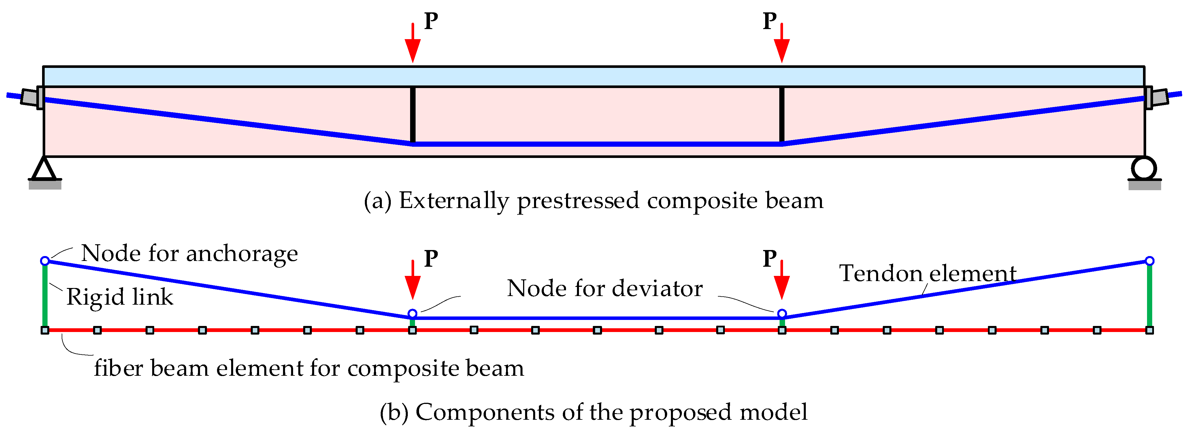
2.1. Schemes of the Proposed Model

The proposed model is mainly applied for the analysis of EPCBs with deformable interfacial connections, such as EPCBs designed with partial shear connections or existing EPCB with degraded shear connectors.
Based on the principles of high computational efficiency and accuracy, the schemes of the proposed model are built, as shown in Figure 1. There are two new types of elements introduced. For the steel-concrete composite beam, a new type of fiber beam element considering nonlinear interfacial connection is proposed, improving the drawbacks of traditional fiber beam element without interface-slip effects. For the external tendons, a multi-node slipping cable element is proposed to model the slip and strain-compatible effects of the external tendon across the deviators. Meanwhile, a rigid link element is built for the connection of two components at the deviators. The FE formulations of these elements are derived and the computational procedures are developed in the OpenSees [37] framework as new element classes. The proposed model and developed procedure provide an effective tool for the flexural behavior analysis of externally prestressed composite beams (EPCBs).

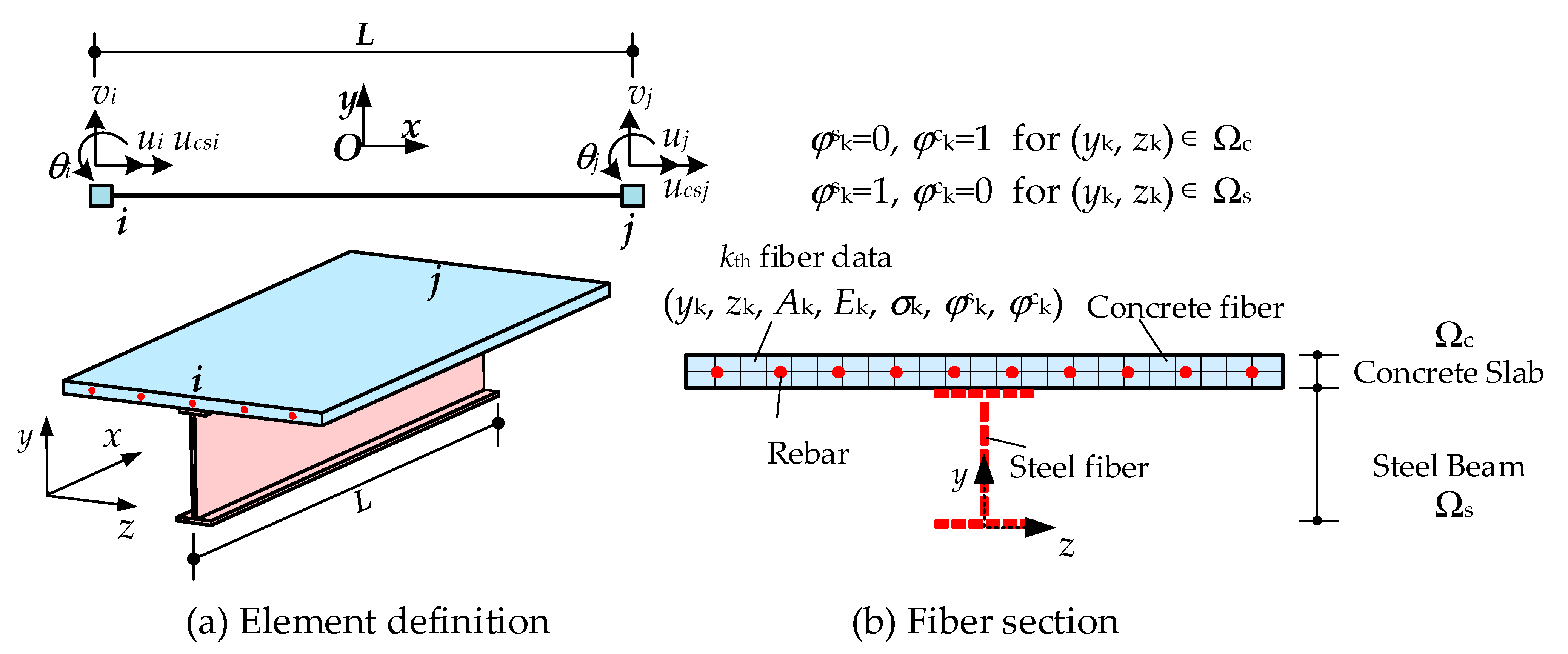
2.2. Fiber Beam Element Model with Nonlinear Interfacial Connection

The fiber beam element model with a nonlinear interfacial connection is built with the idea of inducing the additional DOF into the conventional fiber beam element to describe the interfacial slip deformation. In contrast to the methods in [33,34,35,36], only two additional DOFs describing the relative slip deformation are introduced at both beam ends, and a two-node 8-DOF fiber beam element is proposed, as shown in Figure 2. For each node, four DOFs are defined to describe the kinematics of the composite beam, including the axial displacement u, vertical displacement v, rotation θ and interfacial relative slip ucs (introduced DOF compared with the conventional fiber beam element). The cross-section is defined by discrete fibers, including concrete fibers, steel fibers and reinforcement fibers.
The numbers of element nodes are named i and j. The element local coordinate axial x is defined along the element line and the yOz plane is defined in the cross-section, as shown in Figure 2. The displacement vector u and resistance vector F of the element are defined in Equations (1) and (2), respectively. The axial force N, shear force V, moment M and interfacial shear force Fcs are defined as the resistance force concerning u, v, θ and ucs. The subscript i and j denote the corresponding nodal number.
u = u i v i θ i u c s i u j v j θ j u c s j T
F = N i V i M i F c s i N j V j M j F c s j T
Eliminating the rigid body displacements, the main deformation modes of the element can be labeled axial deformation, rotational deformation and slip deformation, as shown in Figure 3. The basic deformation vector ub can be expressed as Equation (3). The transformation relation between ub and u is shown in Equation (4). cx = (L + ∆ux)/Ln, cx = ∆uy/Ln. L is the initial element length and Ln is the deformed element length. ∆ux and ∆uy denote relative displacement along the local x and y axes, respectively.
u b = Δ u θ θ u c s i u c s j T
u b = P u P = c x c y 0 0 c x c y 0 0 c y / L n c x / L n 1 0 c y / L n c x / L n 0 0 c y / L n c x / L n 0 0 c y / L n c x / L n 1 0 0 0 0 1 0 0 0 0 0 0 0 0 0 0 0 1
With the basic deformation vector ub, the deformation field inside the element can be denoted by the Hermite polynomial interpolation method, as shown in Equation (5), in which ξ = x/L, x is the local coordinate in the element, and 0 ≤ ξ ≤ 1. The axial and slip deformations are interpolated by linear equations and the rotation deformation is interpolated by a quadratic polynomial.
u ¯ x = N x u b = Δ u x θ x u c s x T N x = ξ 0 0 0 0 0 3 ξ 2 4 ξ + 1 3 ξ 2 2 ξ 0 0 0 0 0 1 ξ ξ
E x = ε s x ε c x ϕ x u c s x T = Δ u x x Δ u x + u c s x x θ x x u c s x T = B x u b B x = 1 / L 0 0 0 0 0 6 ξ 4 / L 6 ξ 2 / L 0 0 1 / L 0 0 1 / L 1 / L 0 0 0 1 ξ ξ
The generalized strain tensor E(x) of the section at location x can be expressed as Equation (6) by derivation. εs(x) and εc(x) denote the sectional axial strain of the steel and the concrete beam, respectively. φ(x) denotes the sectional curvature and ucs(x) denotes the interfacial slip displacement at location x.
For the fiber numbered k within the cross-section of the element, the specified data includes fiber centroid coordinates (yk, zk), fiber area Ak, fiber region flag φ k s and φ k c , fiber stress σk and fiber tangent modulus Ek, as shown in Figure 2b. For fibers in the concrete slab ((yk, zk) ∈ Ωc), φ k s = 0 and φ k c = 1 ; otherwise ((yk, zk) ∈ Ωs), φ k s = 1 and φ k c = 0 . Then, the axial strain of fiber k can be yielded by Equation (7). The slip displacement at the location x can be denoted as Equation (8).
ε x = φ s k y , z φ c k y , z y 0 E x = Q y , z E x
u c s x = 0 0 0 1 E x = h E x
The internal virtual work expression can be denoted by the integral computation of the fibers and the shear connector along with the element, as shown in Equation (9). Substituting Equations (4)–(8) into Equation (9), the virtual work expression can be rewritten as Equation (10), in which fcs is the average interfacial shear force per unit length. The resisting force vector F can be identified from Equation (10) and is expressed by Equation (11). q is the element resisting vector in the basic coordinate system and rs(x) is the sectional resisting force vector.
δ W = 0 L A δ ε x σ d A + δ u c s f c s d x
δ W = δ u T · 0 L P T B T x A Q T y , z σ k d A + h T f s d x
F = P T q q = 0 L B T x A Q T y , z σ k d A + h T f s d x = 0 L B T x r s x d x
The element stiffness matrix K can be obtained by the partial derivative of Equation (11) to u, as shown in Equation (12). kg is the geometric stiffness matrix and km is the material stiffness matrix in the basic coordinate system. The derived expression of km is shown in Equation (13), in which ks is the sectional stiffness matrix. Based on the idea of the fiber section method, the integration style of rs and ks can be calculated by the algebraic summary of the total fibers’ contribution, as shown in Equations (14) and (15). The integrations of the km and q of the element are implemented using the Gauss–Lobatto method.
K = F u = u P T q = P T u q + P T q u b u b u = k g + P T k m P
k m = 0 L B T x k s B x d x
k s x = k = 1 n Q T y , z E k Q T y , z + h T ρ s h
r s x = k = 1 n Q T y , z σ k + h T f s
Figure 4 shows the stress and tangent modulus update flow during each iterative calculation process. With applied load, the structural trail deformation is calculated first. Then, the element deformation can be obtained from Equations (3) and (4) and the sectional deformation at the integration point can be calculated using Equation (5). With Equations (6)–(8), the fiber strain ε(x) in the section and the relative deformation ucs(x) can be calculated. Based on the constitutive model of material and interfacial connection, the force and the tangent modulus can be updated. With the summation of fibers in the cross-section at the integration point, the sectional stiffness matrix and resistance vector can be obtained from Equations (14) and (15). From the integration along the beam length, the stiffness matrix and resistance vectors are calculated and then assembled to form the whole structural matrix for the next iteration. In this way, the stiffness matrix and internal force vectors were updated from the fiber to the section and then to the element and structural level in turn. The material, geometric and interfacial nonlinear behaviors of the composite beam were all considered in the proposed element.

2.3. Multi-Node Slipping Cable Element for External Tendon

Ignoring the friction at the deviators, the external tendon usually has the same traction force along its entire length. The traditional truss elements cannot satisfy the compatible relation between different segments. A multi-node slipping cable element was developed to model this behavior. Unlike the equivalent external forces method [28,29,30], the stiffness matrix and resisting force vector of the proposed element are all explicitly derived to improve the numerical convergence.
The configuration of the proposed element is shown in Figure 5, in which np nodes and np-1 segments were defined. The element displacement vector Ut is defined in Equation (16), in which u i , t = u i , t v i , t was the displacement of node i at step t.
U t = u 1 , t u i , t u n p , t 2 n p × 1 T
Assuming that the initial length of the element was L0 which is the sum length of all segments, after deformation, the deformed element length can be expressed by the displacement vector Ut, as shown in Equation (17),
ε t = U t T P t T ϒ t P t U t + R T L 0 L 0
in which,
P t = 1 0 1 1 0 1 1 0 1 1 0 1 2 n p 2 × 2 n p ,   R = d i a g r 1 r j r n p 1 2 n p 2 × 2 n p 2 , r j = cos X cos Y cos Y cos X ,   cos X = x j + 1 , 0 x j , 0 l j , 0 ,   cos Y = y j + 1 , 0 y j , 0 l j , 0 , ϒ t = d i a g l 1 , t 1 I 2 × 2 l j , t 1 I 2 × 2 l n p 1 , t 1 I 2 × 2 , L 0 = L 1 , 0 T L j , 0 T L n p 1 , 0 T T , L j , 0 = l j , 0 0 T .
By the virtual work equation and variation principle, the resisting force vector and stiffness matrix of the element can be derived and expressed in Equations (18) and (19), respectively. Ap is the area of the external tendon, σp and Ep denote the tendon stress and tangent modulus at time t, respectively, which is calculated according to the material constitute model. k t g and k t m denote the geometric and material stiffness matrix, respectively.
f t = σ p A p L 0 T R Γ t P g
K t = k t g + k t m k t g = σ p A p P t T ϒ t Γ t P t k t m = E p A p / L 0 P t T Γ t R T L 0 L 0 T R ϒ t P t
It should be noted that the nodal and segment number of the element was not limited during the derivation. This meant that the proposed element was able to be applied to model external tendons of any profile type. Meanwhile, the geometric and material stiffness matrix is expressed in explicit form, improving the computational convergence.

2.4. Rigid Link between Beam and Tendon

Taking the beam node as the master node and the external tendon node as the slave node, the interaction relationship between the DOFs of the two nodes (DOFs of beam node named uc and DOFs of tendon node named ut) can be expressed as Equation (20). As shown in Figure 6, one end of the rigid link connected to the beam node is the rigid connection and the other end connected to the external tendon is the hinge connection. The translational and rotational displacements of beam nodes lead to the translation of tendon nodes.
u t = 1 0 Δ y 0 0 1 Δ x 0 u c

2.5. Constitutive Model

(1)
Concrete constitutive model
The Concrete02 material in OpenSees is adopted to model the nonlinear behaviors of concrete, as shown in Figure 7a. The compressive stress-strain relationship is assumed in the parabolic-ascending linear-descending form. The tension stress-strain curve is linear elastic before cracking and then linear-softening for cases beyond the cracking strain. The ultimate compressive and tensile strain are determined according to the crushing and cracking energy to mitigate the mesh sensitivity, respectively. The equations are shown in Equations (21) and (22), in which L denotes the element characteristic length, GFc is the concrete crushing energy, GF is the concrete fracture energy, fc is the concrete compression strength, ft is the concrete tension strength, Ec is the initial elastic modulus of concrete. The values of GFc, GF and GF0 are determined following the suggestion of CEB-FIP [38].
ε c u = 2 G F c f c L + ε c 0 ,   G F c = 8.8 f c
ε t u = 2 G F / L f t ,   G F = G F 0 f c / 10 0.7
(2)
Prestressing steel tendon constitutive model
The material nonlinear behaviors of the prestressing tendon are modeled by the Steel02 model in OpenSees, as shown in Figure 7b. Ep and fpy denote the initial elastic modulus and yield strength of the prestressing tendons. bp represents the ratio of strain-hardening modulus to the initial elastic tangent. In this paper, we adopt bp = 0, R0 = 18 for the Steel02 model definition and the default values are used for the other parameters (see http://opensees.berkeley.edu/ (accessed on 1 March 2020)). Meanwhile, the initial prestress σpe is defined in Steel02.
(3)
Constitutive model for steel beam and reinforcements
The Steel01 model is chosen to model the material behaviors of steel beams and reinforcements, as shown in Figure 7c. Es and fy denote the elastic modulus and yield of steel, respectively. b denotes the ratio of strain-hardening modulus to Es. For the steel beam, b = 0.005; for reinforcements, b = 0.0 is adopted in the simulation.
(4)
Interfacial shear-slip model
The interfacial shear-slip constitutive relationship proposed by Ollgaard et al. [39] is employed to simulate the nonlinear interfacial behaviors, as shown in Equation (23). Vu denotes average interfacial shear capacity per unit length. Aus is the average area of the shear stud cross-section per unit length. fs represents the average shear force at the interface under ucs slip displacement. fu is the yield strength of steel studs. n and m are the curve shape calibration parameters according to the shear-slip tests of shear connector specimens. If there were no test data available, the default value m = 0.558 and n = 1 mm−1 can be adopted. Figure 7d shows the interfacial slip-shear curves. In OpenSees, we use the MultiLinear material model to define the curve and the initial modulus is determined as the secant modulus at 0.1 mm slip displacement.
f s = V u 1 e n u c s m V u = 0.43 A u s E c f c 0.7 A u s f u

2.6. Computational Procedure Development

With the derived FE formulations, three types of elements are developed in the OpenSees framework [37] with the C++ programming language. Meanwhile, the Tcl command interpreters are defined in the procedure for the convenient application in the analysis model. The framework of the developed Classes in OpenSees is shown in Figure 8. The advantage of the developed procedure is that there are abundant nonlinear constitutive models and solvers built into the OpenSees software, which can be used conveniently in the numerical model.

2.7. Highlights of the Proposed Model

The highlights of the proposed model can be concluded as follows:
(1)
A new modeling method is proposed by introducing two relative slip DOFs into the ends of the fiber beam element. An 8-DOF fiber beam element was built for the composite beam with material, geometric and interfacial nonlinearity.
(2)
Taking the external tendon as the whole member, a multi-node slipping cable element is proposed with a complete stiffness and resistance matrix. Compared with the equivalent load method, the numerical convergence was improved and can be widely used for external tendons with different profiles.
(3)
The methods and framework of the element classes developed in OpenSees are presented.

3. Experimental Verification

3.1. Verification for the Nonlinear Interfacial Behaviors

Zhang et al. [17] conducted eight simply supported steel-concrete composite beam experiments to test the influence of interfacial shear connection degree on the flexural behaviors. The compared specimens named NCB-4, NCB-5 and NCB-6 were built with different stud spacings, leading to the failure mode differences. The structural details of NCB-4, NCB-5 and NCB-6 are shown in Figure 9. The material properties are listed in Table 1 and Table 2. According to the design details of shear connectors, the average shear capacity per unit length Vu can be calculated using Equation (23). The values of Vu for NCB-4, NCB-5 and NCB-6 were 860 N/mm, 383 N/mm and 688 N/mm, respectively. Additionally, the shear connection degree η was 1, 0.45 and 0.69 for NCB-4, NCB-5 and NCB-6, respectively.
The analysis models of these three tests are built by OpenSees with the newly developed fiber beam element with interfacial slip effects. Meanwhile, the traditional fiber beam element is also employed to model the case without interfacial slip for comparisons. Figure 10a,b show the calculated results of load-deflection and load-slip curves, respectively. Some conclusions can be drawn by observing these comparisons. With an increase in shear connection degree, the stiffness and carrying capacity are both significantly improved. The proposed model and developed procedure can effectively capture the nonlinear interfacial slip behaviors, and the calculated results agree well with the tests.
To further validate the prediction of the proposed model for the failure mode caused by nonlinear interfacial slip behaviors, the interfacial shear-slip curves are output from the models, as shown in Figure 11a,b, which shows the stress distributions along with the height of the failure cross-section at ultimate states. The failure modes observed by Zhang et al. [17] are shown in Figure 12. For the specimen with the lowest shear connection degree, NCB-5, the ultimate interfacial average shear almost reached the specified capacity. The ultimate stress of the top fiber in the concrete slab was lower than its compressive strength, meaning that the failure mode was caused by the interfacial slip rather than the concrete crushing. The observed failure modes caused by split cracks in Figure 12b validate this judgment. For NCB-4, the interfacial slip occurred but did not reach the ultimate states and the top concrete fiber reached its peak strength. The failure mode of NCB-4 is shown in Figure 12a. For the full shear connection model without slip effects, the top concrete fiber was in the stage of compression softening. The concrete slab was crushed and the steel beam showed full section yield, as shown in Figure 11b. The comparisons revealed that interfacial slip effects inevitably existed and significantly influenced the flexural behaviors of the steel-concrete composite beam, even when the shear connection degree was set to 1. The proposed model can effectively predict the flexural capacity, deformation and failure modes of composite beams with interfacial slip effects.

3.2. Verification for the Case of Simply Supported EPCB

Lorenc and Kubica [10] tested the flexural behaviors of externally prestressed steel-concrete composite beams with different tendon profiles. Two specimens, named B3 and B4, are employed to verify the proposed model. B3 and B4 had similar structural dimensions (as shown in Figure 13) except for the tendon profiles, which were draped-style for B3 and straight-style for B4. The average compression strength of concrete fc = 31.7 MPa and the elastic modulus Ec = 28.6 GPa. The yield strength of the steel beam fy = 293 MPa and the yield stress of the cover-plate was 358 MPa. According to the push-out tests of the shear connector, the maximum interfacial shear capacity of a single connector was 75 kN and the authors recommended α = 0.3, β = 0.55. The reinforcements of 8 mm diameter were embedded into the concrete slab, and the yield stress of the rebar was 428 MPa. The external prestressing was implemented using two nominal diameters of 15.7 mm seven-wire strands, whose Ap = 150 mm2, Ep = 197.8 GPa and initial effective prestress σpe = 950 MPa.
The behaviors of specimens are modeled with the proposed model and traditional model, respectively. In the traditional model, the composite beam is modeled by the traditional fiber beam element without shear-slip effects and the external tendons are modeled by multiple truss elements. In the proposed model, the nonlinear interfacial behaviors are considered in the developed fiber beam element and the external tendons are modeled by only one proposed slipping-tendon element. According to the test procedure, the prestressing is applied in the analysis model firstly and then two equal concentrated forces are loaded at mid-span until structural failure.
Figure 14a shows the analysis results of specimen B3. The proposed model shows good agreement with the tests for both load-deflection curves and tendon stress increments. However, for the traditional model, the initial structural stiffness is overestimated due to the ignored interfacial slip and the structural capacity is also slightly overestimated. Meanwhile, the stress increments of the external tendon in the traditional model are different in the side and middle branches due to the strain-incompatible condition in the separated truss element. The stress increment of the side branch truss element (seg-1) is small and that of the middle truss element (seg-2) is large, as shown in Figure 14b. Specimen B4 is prestressed with straight tendons, in which case, the proposed slipping tendon element used is the same as the traditional truss element. The main differences between the two models are the interfacial slip effects. The traditional model overestimates the initial structural stiffness and the proposed model shows a better prediction. Compared with the traditional model, the proposed element significantly improves the prediction accuracy.

3.3. Verification for the Case of Continuous EPCB

The specimen PCCB-4 conducted by Nie et al. [13] is employed to verify the effectiveness of the proposed model for continuous EPCBs. The structural details and layout of PCCB-4 are shown in Figure 15. The properties of the concrete slab are as follows: fc = 30 MPa, Ec = 30 GPa and ft = 2.5 MPa. For the steel beam, the yield strength is 249.3 MPa for the top flange, 272.3 MPa for the bottom flange and 287.7 MPa for the web. The elastic modulus of the steel beam is 200 GPa. The composite beam is prestressed by two unbonded steel tendons in the steel box beam. The cross-section area of the tendon is 139 mm2 and the initial effective prestress is 885.8 MPa. The yield strength of the external tendons is 1860 MPa and the elastic modulus is 200 GPa. The loading scheme is shown in Figure 15.
Two models, including the proposed model and the traditional model presented above, are built to simulate the flexural behaviors of PCCB-4 up to failure. Figure 16 shows the load-deflection curve comparisons, in which a better agreement of the proposed model with the tests is observed. For the prediction of external tendon stress increments, the three segments of the tendon in the traditional model have different behaviors. The stress increment in the seg-3 is small and the one in the middle segment is larger than that found in the tests, causing the overestimation of the flexural capacity. For PCCB-4, the tendon ratio is low and the effects of the overestimated tendon stress on the behaviors are not obvious in consequences. However, for EPCBs with a high external tendon ratio, the traditional model overestimates the flexural capacity significantly. In the proposed model, the external tendon is modeled by the strain-compatible slipping tendon element which was close to the actual behavior of the external tendon. The proposed model can be used to model the behaviors of EPCB with multiple segments of external tendons.

4. Parametric Analysis

The verified finite element model is employed to conduct a parameter analysis of factors that affect the flexural behaviors of EPCBs. The main discussed factors included the deviator spacing, the effective height of external tendons and the interfacial shear capacity. The structural details of the reference model are shown in Figure 17. The material properties were as follows: for the concrete slab, the compressive strength fc = 30 MPa and the elastic modulus Ec = 30 GPa; for the steel beam, the yield strength fy = 300 MPa and the elastic modulus Es = 200 GPa; for the external tendons, the yield strength fpy = 1860 MPa, the elastic modulus Ep = 195 GPa, and the initial effective prestress σpe = 1000 MPa.
In the reference beam, the deviator spacing Sd = 6 m, the effective height of external tendon dp = 550 mm, and the average interfacial shear capacity at the unit length was set Vu = 900 N/mm (shear connector degree η = 1). During the parameter analysis, the parameters’ values were all the same as those of the reference beam except the discussed parameter. For each parameter analysis, two loading types including one-point loading at mid-span and uniform loading were applied and analyzed.

4.1. Effects of Deviator Spacing

Based on the reference model, the deviator spacing Sd is set to range from 0.4 m to 19.6 m at intervals of 0.4 m. A total of 49 analysis models are built to discuss the effects of deviator spacing on the structural behaviors. The calculated results of tendon stress increments, effective height decrements dp and flexural capacity are presented in Figure 18. With an increase of deviator spacing, the stress increments are slightly decreased but the decrements of dp are increased. The results reveal that the second-order effects are significant for cases with large deviator spacing. Along with the variation in Sd from 0.4 m to 19.6 m, the flexural capacity decreases by 6.7% under one-point loading states and 10.8% under uniform loading states. The increasing Sd causes a decrease in flexural capacity.

4.2. Effects of External Tendon Effective Height

The external tendon effective height dp ranges from 110 mm to 550 mm at intervals of 40 mm. A total of 12 analysis models are built to discuss the effects of dp on the structural behaviors. The results are shown in Figure 19. Interestingly, we find that the effects of dp on its decrements are small, which is different from the effects of Sd. With an increase in dp, the stress increments and flexural capacity are increased. The stress increments and decrements of dp under uniform loading are all larger than the ones under one-point loading states. Along with the variation of dp from 110 mm to 550 mm, the flexural capacity increases by 20.0% under one-point loading states and 23.0% under uniform loading states. The increasing dp increases the flexural capacity.

4.3. Effects of Interfacial Slip

In this section, the Vu ranges from 100 to 1500 N/mm (shear connection degree η ranges from 0.11 to 1.67) to analyze the effects of shear connection on the flexural behaviors. The load-displacement curves of composite beams with various Vu under one-point loading and uniform loading are shown in Figure 20a,b, respectively. With the increase in Vu, the structural stiffness and capacity are increased. Figure 21 shows the stress increments, decrements of dp and flexural capacity variation caused by an increase in Vu. The results show that the variation of stress increments and dp decrements are not monotonic. For weak shear connection models (Vu ≤ 300 N/mm for one-point loading states, Vu ≤ 400 N/mm for uniform loading states), the structural failure is mainly caused by interfacial slip, and the increasing interfacial shear capacity leads to larger structural deformation capacity before peak loads. Then, the stress increments and decrements of dp increase with an increase in Vu. For stronger shear connection models (Vu > 300 N/mm for one-point loading states, Vu > 400 N/mm for uniform loading states), the concrete slab crushing failure is replaced by interfacial slip failure. The stiffness contribution of the concrete slab decreases the structural ultimate deformation and then causes the decreasing stress increments and dp decrements. For the cases of Vu reaching the full shear connection, the stress increments and dp decrements show almost no change.
For the composite beam with partial interaction, the interactions between external tendons and interfacial shear-slip were complicated. The model in this paper provides an effective method for the flexural analysis of EPCBs.

5. Conclusions

In this paper, a new beam-tendon hybrid model consisting of fiber beam elements and slipping cable element is proposed to analyze the flexural behaviors of EPCBs. The mechanical characteristics of EPCBs, including the material and geometric nonlinearities, interfacial slip effects, and the unbonded effects of the external tendon are all considered in the model. The FE formulations of the proposed elements are presented and the computational procedure is developed in the OpenSees framework as the new element classes. The proposed model is validated by comparisons with experimental tests and the parametric analysis is conducted. The main conclusions can be summarized as follows:
  • Interfacial slip effects are inevitable for steel-concrete composite beams during their service life, even when they are designed with full shear connections. The structural stiffness, capacity and failure modes are all affected. The proposed fiber beam element model considering interfacial slip effects can be used to predict the capacity, deformation and failure mode, which are all verified to agree well with the experimental results.
  • Ignoring the friction at the deviators, the external tendon has equal traction along its whole length. The conventional truss element could not satisfy the strain-compatibility property in multiple segments, causing some overestimation of the stress increments and flexural capacity. The proposed slipping cable element is built considering the strain-compatibility property, which shows better agreement with the experimental results.
  • The parameter analysis results reveal that the deviator spacing, external tendon effective height, interfacial shear capacity and loading type all affect the flexural capacity of EPCBs. An increase in the deviator spacing decreases the ultimate effective height of the external tendon, which then leads to a decrease in the flexural capacity. The increased external tendon effective height increases the ultimate stress increments and flexural capacity. With an increase in the interfacial shear capacity, the flexural capacity increases gradually but the stress increments and effective height of the tendon do not vary monotonously. The proposed model provides an effective method for predicting the flexural behaviors of EPCBs.

Author Contributions

Conceptualization, methodology, software, validation, writing—original draft preparation, W.Y.; project administration, L.C.; supervision, writing—review and editing, B.H.; data curation, H.X.; visualization, Y.S. All authors have read and agreed to the published version of the manuscript.

Funding

This research was funded by the Funds of China Railway Economic Planning and Research Institute, funding number 2021BSH01; Project of Science and Technology Research Development Plan of China Railway, funding numbers K2021G013 and N2021G046; Project from Key Laboratory of Transport Industry of Bridge Detection Reinforcement Technology (Beijing), funding number C21M00030.

Institutional Review Board Statement

Not applicable.

Informed Consent Statement

Not applicable.

Data Availability Statement

Not applicable.

Conflicts of Interest

The authors declare no conflict of interest. The funders had no role in the design of the study; in the collection, analyses, or interpretation of data; in the writing of the manuscript, or in the decision to publish the results.

References

  1. Yan, L.B.; Han, B.; Fan, L.; Li, X. Fatigue Damage of PBH Shear Connector of Steel-Concrete Composite Structure. Eng. Struct. 2020, 213, 110540. [Google Scholar] [CrossRef]
  2. El-Zohairy, A.; Salim, H.; Saucier, A. Steel-Concrete Composite Beams Strengthened with Externally Post-Tensioned Tendons under Fatigue. J. Bridge Eng. 2019, 24, 04019027. [Google Scholar] [CrossRef]
  3. Xu, J.; Sun, H.; Chen, W.; Guo, X. Experiment-Based Fatigue Behaviors and Damage Detection Study of Headed Shear Studs in Steel-Concrete Composite Beams. Appl. Sci. 2021, 11, 8297. [Google Scholar] [CrossRef]
  4. Kim, S.-H.; Park, J.-S.; Jung, W.-T.; Kim, T.-K.; Park, H.-B. Experimental Study on Strengthening Effect Analysis of a Deteriorated Bridge Using External Prestressing Method. Appl. Sci. 2021, 11, 2478. [Google Scholar] [CrossRef]
  5. Kim, S.-H.; Park, J.-S.; Jung, W.-T.; Kang, J.-Y. Strengthening Effect of the External Prestressing Method That Simulated a Deterioration Bridge. Appl. Sci. 2021, 11, 2553. [Google Scholar] [CrossRef]
  6. Alqam, M.; Alkhairi, F. Numerical and Analytical Behavior of Beams Prestressed with Unbonded Internal or External Steel Tendons: A State-of-the-Art Review. Arab. J. Sci. Eng. 2019, 44, 8149–8170. [Google Scholar] [CrossRef]
  7. Ayyub, B.M.; Sohn, Y.G.; Saadatmanesh, H. Prestressed Composite Girders under Positive Moment. J. Struct. Eng. 1990, 116, 2931–2951. [Google Scholar] [CrossRef]
  8. Chen, S.; Gu, P. Load Carrying Capacity of Composite Beams Prestressed with External Tendons under Positive Moment. J. Constr. Steel Res. 2005, 61, 515–530. [Google Scholar] [CrossRef]
  9. Chen, S.M. Experimental Study of Prestressed Steel-Concrete Composite Beams with External Tendons for Negative Moments. J. Constr. Steel Res. 2005, 61, 1613–1630. [Google Scholar] [CrossRef]
  10. Lorenc, W.; Kubica, E. Behavior of Composite Beams Prestressed with External Tendons: Experimental Study. J. Constr. Steel Res. 2006, 62, 1353–1366. [Google Scholar] [CrossRef]
  11. Chen, S.; Wang, X.; Jia, Y. A Comparative Study of Continuous Steel-Concrete Composite Beams Prestressed with External Tendons: Experimental Investigation. J. Constr. Steel Res. 2009, 65, 1480–1489. [Google Scholar] [CrossRef]
  12. Chen, S.; Jia, Y.; Wang, X. Experimental Study of Moment Redistribution and Load Carrying Capacity of Externally Prestressed Continuous Composite Beams. Struct. Eng. Mech. 2009, 31, 605–619. [Google Scholar] [CrossRef]
  13. Nie, J.; Tao, M.; Cai, C.S.; Li, S. Deformation Analysis of Prestressed Continuous Steel-Concrete Composite Beams. J. Struct. Eng. 2009, 135, 1377–1389. [Google Scholar] [CrossRef]
  14. Sun, Q.; Yang, Y.; Fan, J.; Zhang, Y.; Bai, Y. Effect of Longitudinal Reinforcement and Prestressing on Stiffness of Composite Beams under Hogging Moments. J. Constr. Steel Res. 2014, 100, 1–11. [Google Scholar] [CrossRef]
  15. Hassanin, A.I.; Shabaan, H.F.; Elsheikh, A.I. Cyclic Loading Behavior on Strengthened Composite Beams Using External Post-Tensioning Tendons (Experimental Study). Structures 2021, 29, 1119–1136. [Google Scholar] [CrossRef]
  16. El-Sisi, A.A.; Hassanin, A.I.; Shabaan, H.F.; Elsheikh, A.I. Effect of External Post-Tensioning on Steel-Concrete Composite Beams with Partial Connection. Eng. Struct. 2021, 247, 113130. [Google Scholar] [CrossRef]
  17. Zhang, J.; Hu, X.; Fu, W.; Du, H.; Sun, Q.; Zhang, Q. Experimental and Theoretical Study on Longitudinal Shear Behavior of Steel-Concrete Composite Beams. J. Constr. Steel Res. 2020, 171, 106144. [Google Scholar] [CrossRef]
  18. Wang, B.; Huang, Q.; Liu, X.; Li, W. Experimental Investigation of Steel-Concrete Composite Beams with Different Degrees of Shear Connection under Monotonic and Fatigue Loads. Adv. Struct. Eng. 2018, 21, 227–240. [Google Scholar] [CrossRef]
  19. Alsharari, F.; El-Zohairy, A.; Salim, H.; El-Din El-Sisi, A. Pre-Damage Effect on the Residual Behavior of Externally Post-Tensioned Fatigued Steel-Concrete Composite Beams. Structures 2021, 32, 578–587. [Google Scholar] [CrossRef]
  20. Nie, J.; Tao, M.; Cai, C.S.; Li, S. Analytical and Numerical Modeling of Prestressed Continuous Steel-Concrete Composite Beams. J. Struct. Eng.-ASCE 2011, 137, 1405–1418. [Google Scholar] [CrossRef]
  21. El-Zohairy, A.; Salim, H.; Shaaban, H.; Mustafa, S.; El-Shihy, A. Finite-Element Modeling of Externally Posttensioned Composite Beams. J. Bridge Eng. 2015, 20, 04015018. [Google Scholar] [CrossRef]
  22. El-Zohairy, A.; Salim, H. Parametric Study for Post-Tensioned Composite Beams with External Tendons. Adv. Struct. Eng. 2017, 20, 1433–1450. [Google Scholar] [CrossRef]
  23. da Rocha Almeida, M.M.; Clemente de Souza, A.S.; de Albuquerque, A.T.; Rossi, A. Parametric Analysis of Steel-Concrete Composite Beams Prestressed with External Tendons. J. Constr. Steel Res. 2022, 189, 107087. [Google Scholar] [CrossRef]
  24. Sanchez, B.d.S.; Tamayo, J.P.; Morsch, I.B.; Miranda, M.P. A Nonlinear Geometric Model for Pre-Stressed Steel-Concrete Composite Beams. J. Braz. Soc. Mech. Sci. Eng. 2021, 43, 233. [Google Scholar] [CrossRef]
  25. Alsharari, F.; El-Zohairy, A.; Salim, H.; El-Sisi, A.E.-D. Numerical Investigation of the Monotonic Behavior of Strengthened Steel-Concrete Composite Girders. Eng. Struct. 2021, 246, 113081. [Google Scholar] [CrossRef]
  26. Palomino Tamayo, J.L.; Franco, M.I.; Morsch, I.B.; Desir, J.M.; Wayar, A.M.M. Some Aspects of Numerical Modeling of Steel-Concrete Composite Beams with Prestressed Tendons. Lat. Am. J. Solids Struct. 2019, 16, e219. [Google Scholar] [CrossRef] [Green Version]
  27. Lou, T.; Lopes, S.M.R.; Lopes, A.V. Numerical Modeling of Externally Prestressed Steel-Concrete Composite Beams. J. Constr. Steel Res. 2016, 121, 229–236. [Google Scholar] [CrossRef]
  28. Lou, T.; Karavasilis, T.L. Numerical Assessment of the Nonlinear Behavior of Continuous Prestressed Steel-Concrete Composite Beams. Eng. Struct. 2019, 190, 116–127. [Google Scholar] [CrossRef]
  29. Lou, T.; Karavasilis, T.L. Numerical Evaluation of Prestressed Steel-Concrete Composite Girders with External FRP or Steel Tendons. J. Constr. Steel Res. 2019, 162, 105698. [Google Scholar] [CrossRef]
  30. Lou, T.; Karavasilis, T.L.; Chen, B. Assessment of Second-Order Effect in Externally Prestressed Steel-Concrete Composite Beams. J. Bridge Eng. 2021, 26, 04021024. [Google Scholar] [CrossRef]
  31. El-Zohairy, A.; Alsharari, F.; Salim, H. Analytical Model and Parametric Study for Externally Post-Tensioned Reinforced Concrete-Steel Composite Beams. Structures 2020, 27, 411–423. [Google Scholar] [CrossRef]
  32. Zhang, Q.; Jia, D.; Bao, Y.; Dong, S.; Cheng, Z.; Bu, Y. Flexural Behavior of Steel-Concrete Composite Beams Considering Interlayer Slip. J. Struct. Eng. 2019, 145, 04019084. [Google Scholar] [CrossRef]
  33. Dall’Asta, A.; Dezi, L.; Leoni, G. Failure Mechanisms of Externally Prestressed Composite Beams with Partial Shear Connection. Steel Compos. Struct. 2002, 2, 315–330. [Google Scholar] [CrossRef]
  34. Dall’Asta, A.; Zona, A. Finite Element Model for Externally Prestressed Composite Beams with Deformable Connection. J. Struct. Eng. 2005, 131, 706–714. [Google Scholar] [CrossRef]
  35. Zona, A.; Ragni, L.; Dall’Asta, A. Finite Element Formulation for Geometric and Material Nonlinear Analysis of Beams Prestressed with External Slipping Tendons. Finite Elem. Anal. Des. 2008, 44, 910–919. [Google Scholar] [CrossRef]
  36. Sousa, J.B.M., Jr.; Parente, E., Jr.; Lima, E.M.F.; Oliveira, M.V.X. Beam-Tendon Finite Elements for Post-Tensioned Steel-Concrete Composite Beams with Partial Interaction. J. Constr. Steel Res. 2019, 159, 147–160. [Google Scholar] [CrossRef]
  37. Mckenna, F.; Fenves, G. Opensees 2.5.0, Computer Software; UC Berkeley: Berkeley, CA, USA, 2015; Available online: http://opensees.berkeley.edu (accessed on 1 March 2020).
  38. CEB-FIP, Model Code 2010; Thomas Telford: Lausanne, Switzerland, 2010.
  39. Ollgaard, J.G.; Slutter, R.G.; Fisher, J.G. Shear Strength of Stud Shear Connections in Lightweight and Normal Weight Concrete. AISC Eng. J. 1971, 8, 55–64. [Google Scholar]
Figure 1. Externally prestressed composite beam and the proposed model components.
Applsci 12 04699 g001
Figure 2. Fiber beam element and fiber section definition.
Applsci 12 04699 g002
Figure 3. Deformation modes of the proposed fiber beam element.
Applsci 12 04699 g003
Figure 4. Stress and modulus update flow during the iterative calculation process.
Applsci 12 04699 g004
Figure 5. Configuration of the multi-node slipping cable element.
Applsci 12 04699 g005
Figure 6. The rigid link connection between the beam and tendon elements.
Applsci 12 04699 g006
Figure 7. Constitutive model in the analysis of EPCB.
Applsci 12 04699 g007
Figure 8. The framework developed in OpenSees.
Applsci 12 04699 g008
Figure 9. Structural details of specimens NCB-4, NCB-5 and NCB-6.
Applsci 12 04699 g009
Figure 10. Comparisons of analysis results with tests of NCB-4, NCB-5 and NCB-6.
Applsci 12 04699 g010
Figure 11. Analysis of failure modes by the calculated results.
Applsci 12 04699 g011
Figure 12. Failure modes observed in the tests.
Applsci 12 04699 g012
Figure 13. Structural details of specimens B3 and B4.
Applsci 12 04699 g013
Figure 14. Analysis results of specimens B3 and B4.
Applsci 12 04699 g014
Figure 15. Structural details of specimen PCCB-4.
Applsci 12 04699 g015
Figure 16. Analysis results of specimens PCCB-4.
Applsci 12 04699 g016
Figure 17. Structural details of the reference model.
Applsci 12 04699 g017
Figure 18. Effects of deviator spacing on flexural responses of EPCB.
Applsci 12 04699 g018
Figure 19. Effects of external tendon effective height on flexural responses of EPCB.
Applsci 12 04699 g019
Figure 20. Load-displacement curves with different interfacial shear capacities.
Applsci 12 04699 g020
Figure 21. Effects of interfacial slip on flexural responses of EPCB.
Applsci 12 04699 g021
Table 1. Material properties of steel in NCB-4, NCB-5 and NCB-6.
ComponentsYield Strength (MPa)Ultimate Strength (MPa)Elastic Modulus (MPa)
Rebar φ64405242.23 × 105
Steel Beam3424472.23 × 105
Shear Studs488552-
Table 2. Material properties of concrete in NCB-4, NCB-5 and NCB-6.
SpecimenCubic Compressive Strength (MPa)Prismatic Compressive Strength (MPa)Elastic Modulus (MPa)
NCB-430.022.822,800
NCB-529.422.322,300
NCB-635.627.127,100
Publisher’s Note: MDPI stays neutral with regard to jurisdictional claims in published maps and institutional affiliations.

