Communication

A Wideband Eight-Element Antenna with High Isolation for 5G New-Radio Applications

College of Electrical and Electronic Engineering, Wenzhou University, Wenzhou 325035, China
*
Author to whom correspondence should be addressed.
Appl. Sci. 2023, 13(1), 137; https://doi.org/10.3390/app13010137
Submission received: 8 November 2022 / Revised: 16 December 2022 / Accepted: 19 December 2022 / Published: 22 December 2022
(This article belongs to the Special Issue Antenna Analysis and Design)

Abstract

:

Featured Application

The presented MIMO antenna can be a good choice for 5G NR applications.

Abstract

A wideband multiple-input multiple-output (MIMO) antenna with high isolation for fifth-generation (5G) new-radio (NR) smartphone employment operating at a range from 3.3–5 GHz is presented in the paper. The wideband antenna is comprised of eight identical radiation units and applies defected ground structure (DGS) to offer higher isolation between antenna units. Each of the antenna elements is formed of a C-shaped microstrip line, two triangle-shaped strips and a rectangular strip. The measurement results present that the transmission coefficients of the presented antenna are smaller than −18 dB in the required wideband, and the envelope correlation coefficient (ECC) values are better than 0.005. The realized gain and efficiency of the designed antenna are about 3.5 dBi and higher than 75%, respectively. The volume of this total antenna is 150 × 75 × 7 mm3, and the measurement of each antenna unit is merely 6.8 mm × 7 mm × 0.8 mm ( 0.077   λ × 0.08   λ × 0.009   λ , λ is the wavelength of 3.4 GHz). The presented MIMO antenna is suitable for 5G new-radio (NR) smartphone applications.

1. Introduction

With the fast growth of fifth-generation (5G) wireless networks and the expectation of higher data transmission rates, increasing challenges have been generated in recent years. To meet these demands, numerous technologies have been studied on the corresponding antenna design [1,2,3]. Multiple-input multiple-output (MIMO) is regarded as an effective technology for increasing spectrum efficiency and channel capacity. However, the antenna units are required to be compact, due to the limited space provided for mobile terminal antennas. Hence, it is difficult to achieve high isolation between antenna elements in the desired frequency bands, which means the aim of improving the isolation MIMO antenna is a herculean technical task [4,5,6].
Recently, a number of MIMO 5G antennas have been provided [7,8,9,10,11,12,13,14,15,16,17,18]. These antennas operate in narrow single-band [7,8], multi-band [9,10,11,12], and wideband [13,14,15,16,17,18]. In [7], a circular-shaped strip with a circular groove and a square-shaped groove at one side is proposed to achieve desired single band. An antenna pair composed of a slot antenna of stepped impedance and a monopole antenna of T-shape is presented in [11] to obtain good impendence matching in triple frequency bands. A modified parasitic strip is employed to achieve wideband for 5G mobile terminal applications [13,15]. In [14], four pairs of compact antenna elements are made of a radiator and two concentric annular slots to make this antenna system operate in a wideband of 3.3–7.1 GHz.
Based on the contrivance, manufacture, and testing of waveguided electric metamaterials (MTM) and the microstrip antenna arrays with weakening coupling [7,8], and to weaken the influence between each antenna unit, many technologies have been put forward, such as self-isolated [9,10,15], asserting neutral line [9], elec and DGS [12,13,17,18,19,20]. Adopting the technique of self-neutralization between the monopole antenna and the co-located loop antenna to contribute to satisfying improving isolation of larger than 16.5 dB is presented in [9]. In [17], the introduction of the DGS can change the ground current to adjust the resonance and reduce the current coupling between antenna ports. In addition, open-ended slots in [18] act as DGS to obtain a compact size and improve the isolation between antenna elements.
As an important development technology of mobile communication, 5G is applied to two spectrum scopes of sub-6 GHz and MMW bands [21,22,23]. It is well known that the 5G NR ranges contain N77, N78, and N79. In addition, N78 is assigned to European Union (EU); China selects N77 and N79. In [15,16], the MIMO antenna with eight elements can operate in a wideband that covers 5G NR N77 and N79.
In this work, the designed eight-element antenna includes the formation of eight same elements and DGS to acquire good performance. Each antenna unit is formed of a C-shaped strip, two triangle-shaped strips and a rectangular strip to attain a wideband of 3.3–5 GHz. Furthermore, the volume of the antenna unit is merely 6.8 × 7 × 0.8 mm3, so the wideband with a compact antenna element is realized innovatively. The results of the measurement show that the presented 5G antenna can contain 5G NR N77 (3.3–4.2 GHz) and N79 (4.4–5 GHz). The mutual coupling and values of ECC are smaller than −18 dB and 0.005 in the desired wideband, respectively. The existence of DGS can skillfully decrease the interaction between antenna units and increase the efficiency of the designed antenna, which is at least 75%.

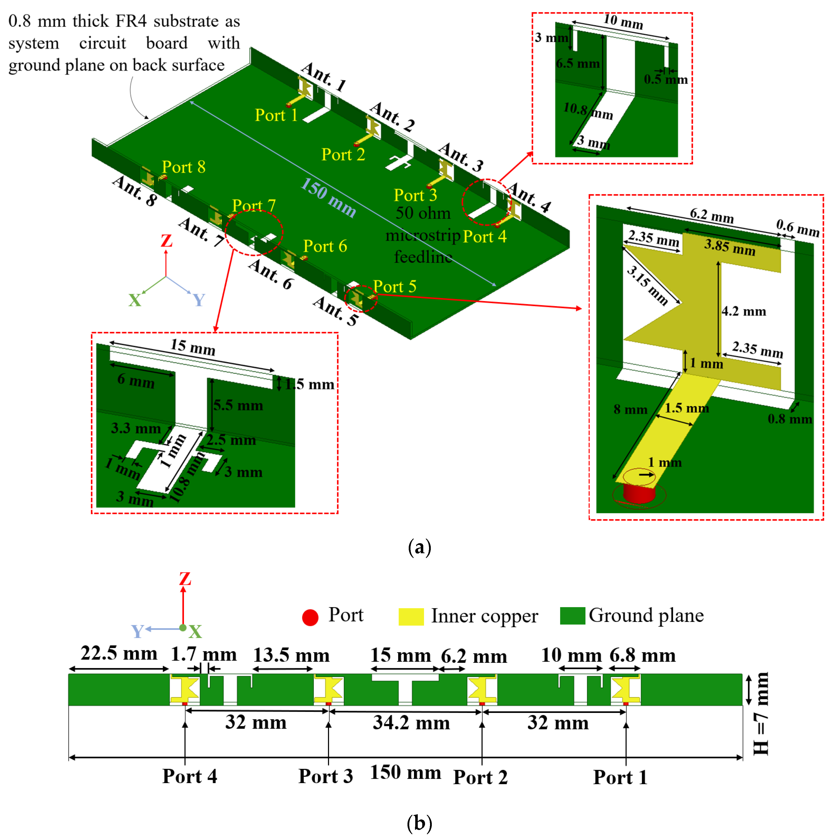
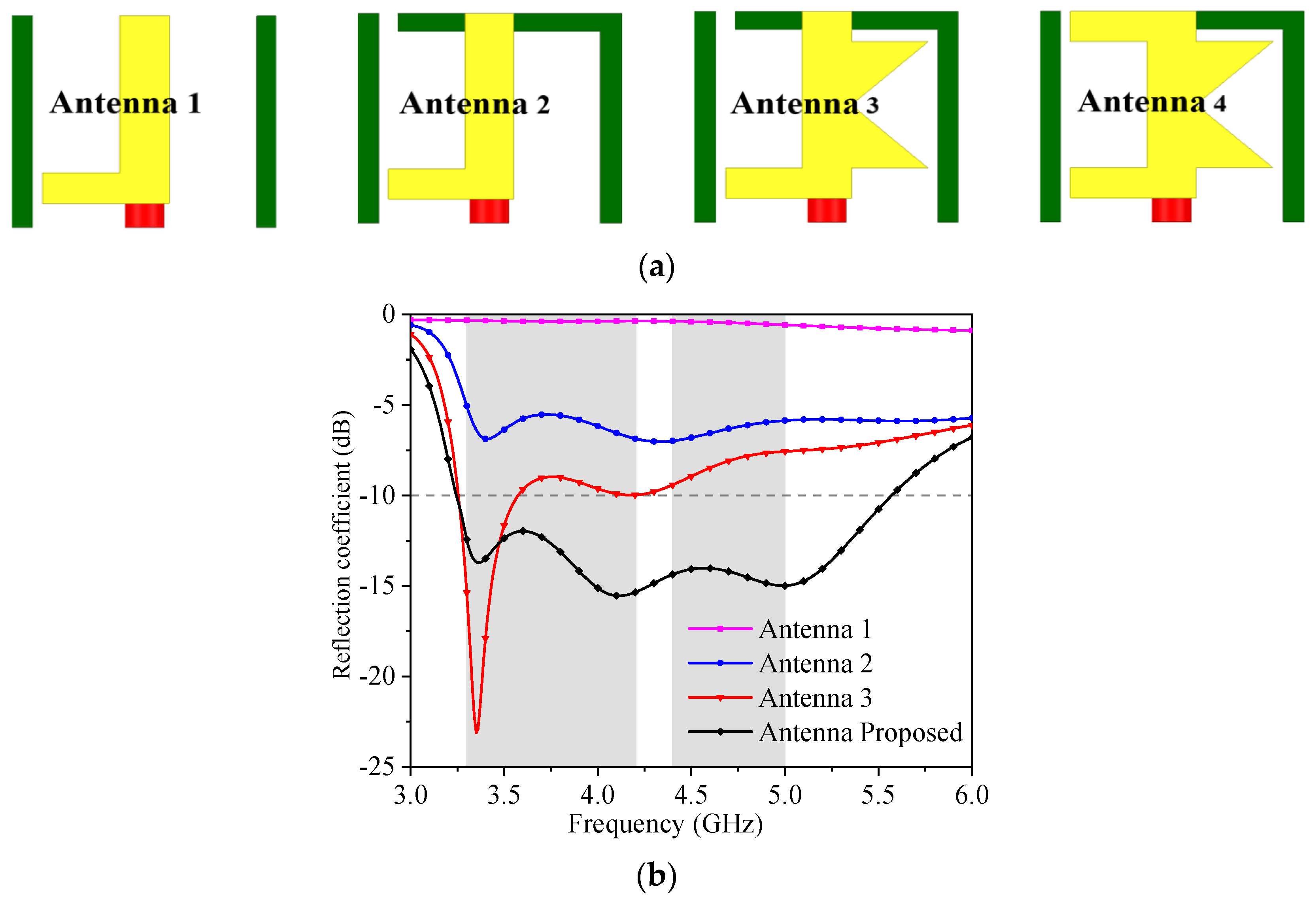
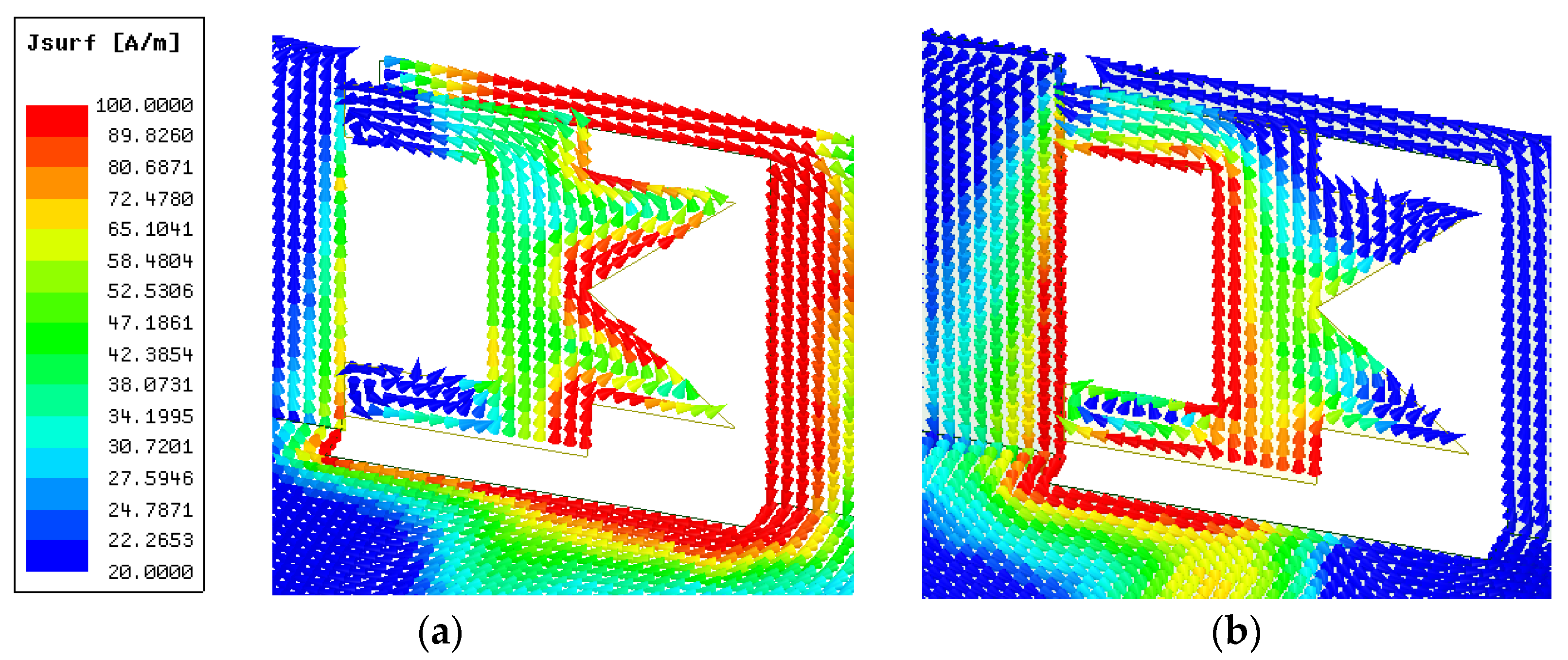
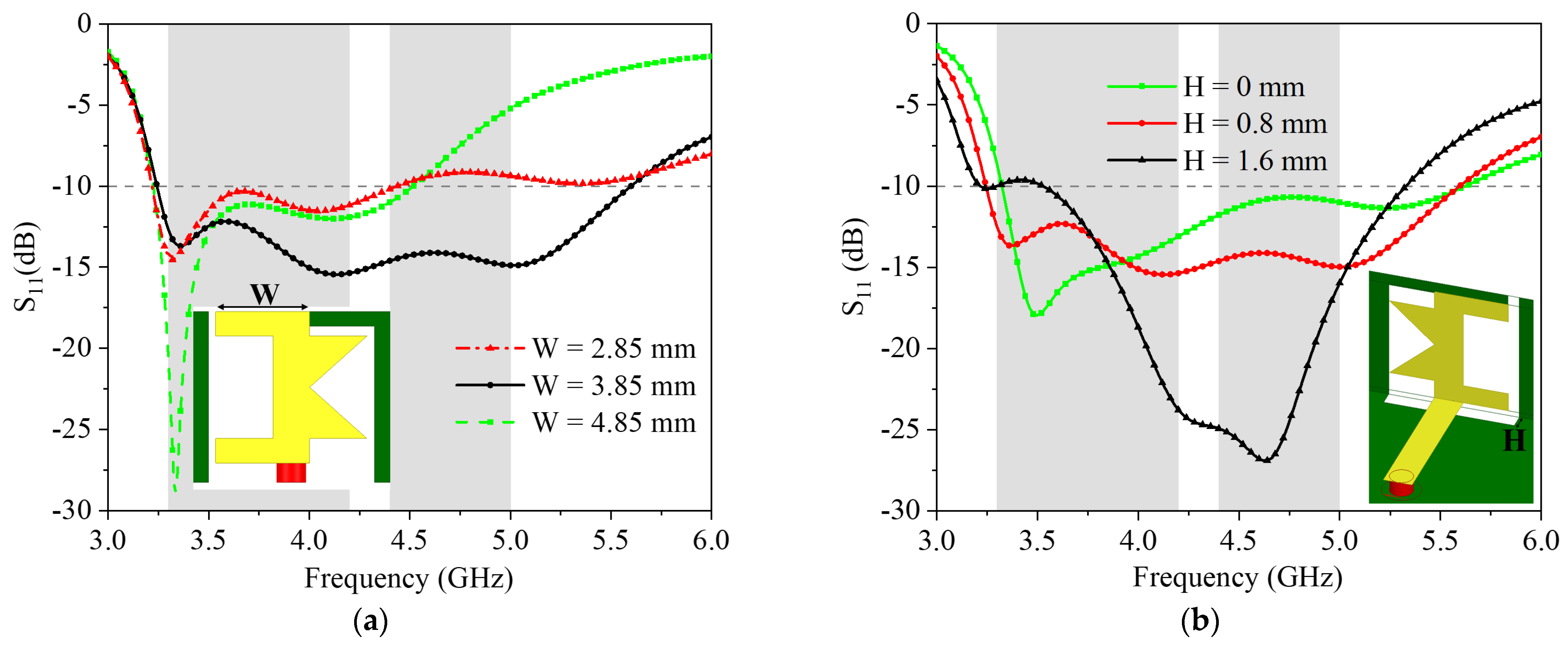
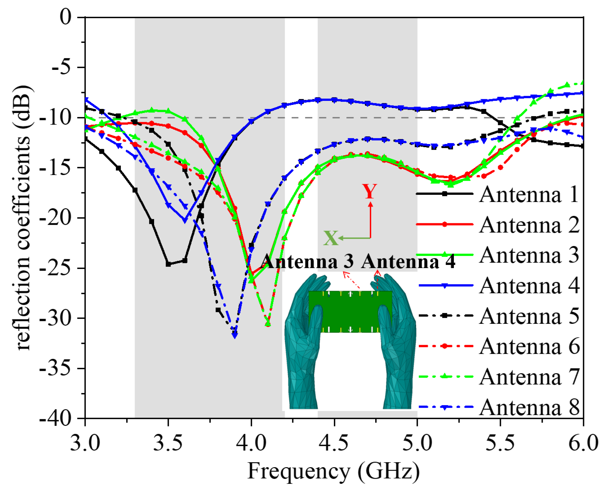
2. The Design and Simulation of the Presented Antenna

The geometry and measurements of the wideband eight-element antenna are presented in Figure 1. The MIMO antenna system is made up of a mainboard and two sideboards perpendicular to the mainboard. The sizes of the mainboard and the sideboard are 150 × 73.4 × 0.8 mm3 and 150 × 7 × 0.8 mm3, respectively. The metal ground surface is in contact with the back of the mainboard and the outside of two sideboards. Eight antenna units are symmetrically placed on the inside of the same two sideboards. In addition, the motherboard and two sideboards are made of an FR4 substrate with εr of 4.4 and tanδ of 0.02. A microstrip feeder of 50 Ω enables the designed antenna to achieve better impendence matching. Every antenna unit consists of a C-shaped strip and two triangle-shaped strips. The structure of a C-shaped strip with two triangle-shaped strips can realize a wideband of 3.3–5 GHz, and the measurement of the antenna elements is only 6.8 × 7 × 0.8 mm3. On the bottom of the mainboard and the outside of two sideboards, the isolation structure contains a T-shaped trough with two square strips and a T-shaped groove connected to a T-shaped trough with two square strips on the ground.
To understand the theory of the presented wideband antenna, the evolution shapes, reflection coefficients, surface current, optimal parameter analysis, and transmission coefficients of the presented antenna have been analyzed.
The layout of the whole antenna structure and the designed antenna simulation results are acquired with HFSS. The evolution and reflection coefficients of the antenna are displayed in Figure 2. The introduction of the rectangular strip on the top of the rectangular groove of Antenna 2 can reduce return loss in the whole frequency band. The two triangle-shaped strips of Antenna 3 are used for achieving −6 dB S11 at 3.3 GHz. Finally, the introduction of a rectangular strip of Antenna 4 can achieve a wideband −10 dB impedance band which can include 3.3–5 GHz.
Figure 3 shows the simulation result of the surface current distribution of the presented antenna. The surface current distribution is concentrated on the rectangular strip of the top of the rectangular groove and two triangle-shaped strips at 3.4 GHz. When the frequency is 4.9 GHz, the surface current is mostly focused on the C-shaped strip.
In Figure 4, the S11 simulation results of the designed antenna with dissimilar values of W and H are presented. When W is 3.85 mm, Figure 4a demonstrated that S11 of −10 dB bandwidth satisfies the frequency band at 3.22–5.6 GHz, which contains 3.3–5 GHz. As shown in Figure 4b, the −10 dB S11 can meet the requirement of the entire band range when the value of H is 0.8 mm.
The simulated transmission coefficients of the presented antenna with or without the structure reducing the interaction are presented in Figure 5, which demonstrates that the structure of a T-shaped groove can increase isolation between antenna elements. The surface current is retrained and its direction is changed by the T-shaped groove. Accordingly, it expands the gap between each port to attenuate mutual coupling between antenna units. Moreover, as illustrated in Figure 5, the T-shaped groove with two rectangular strips connected to a T-shaped groove forms a parallel structure to achieve better isolation in the lower frequency of 3–4 GHz.
The robustness and usefulness of the designed system of MIMO antenna are proved by a study of an application scene of holding MIMO in dual-hand mode (DHM). In Figure 6 and Figure 7, the S-parameter simulation results in DHM are presented, and it shows that the −10 dB bandwidth of Ant. 1 and Ant. 4 cannot cover 3.3–5 GHz. The simulation results of reflection coefficients less than −10 dB of Ant. 2, Ant. 3, Ant. 5, Ant. 6, Ant. 7, and Ant. 8 can cover the 3.3–5 GHz frequency band. In addition, the simulated transmission coefficients are smaller than −15 dB in 3.3–5 GHz. The simulated three-dimension (3D) radiation patterns are presented in Figure 8 when Ant. 3 and Ant. 4 work at 3.4 GHz and 4.9 GHz, respectively. Figure 9 plots the simulation results of the distribution of specific absorption rate (SAR) when Ant. 5 and 6 are independently operated at two resonate modes with 100 mW input power. In Figure 9, the SAR maximum value of about 1 W/kg is obtained at 3.4 GHz and 4.9 GHz.

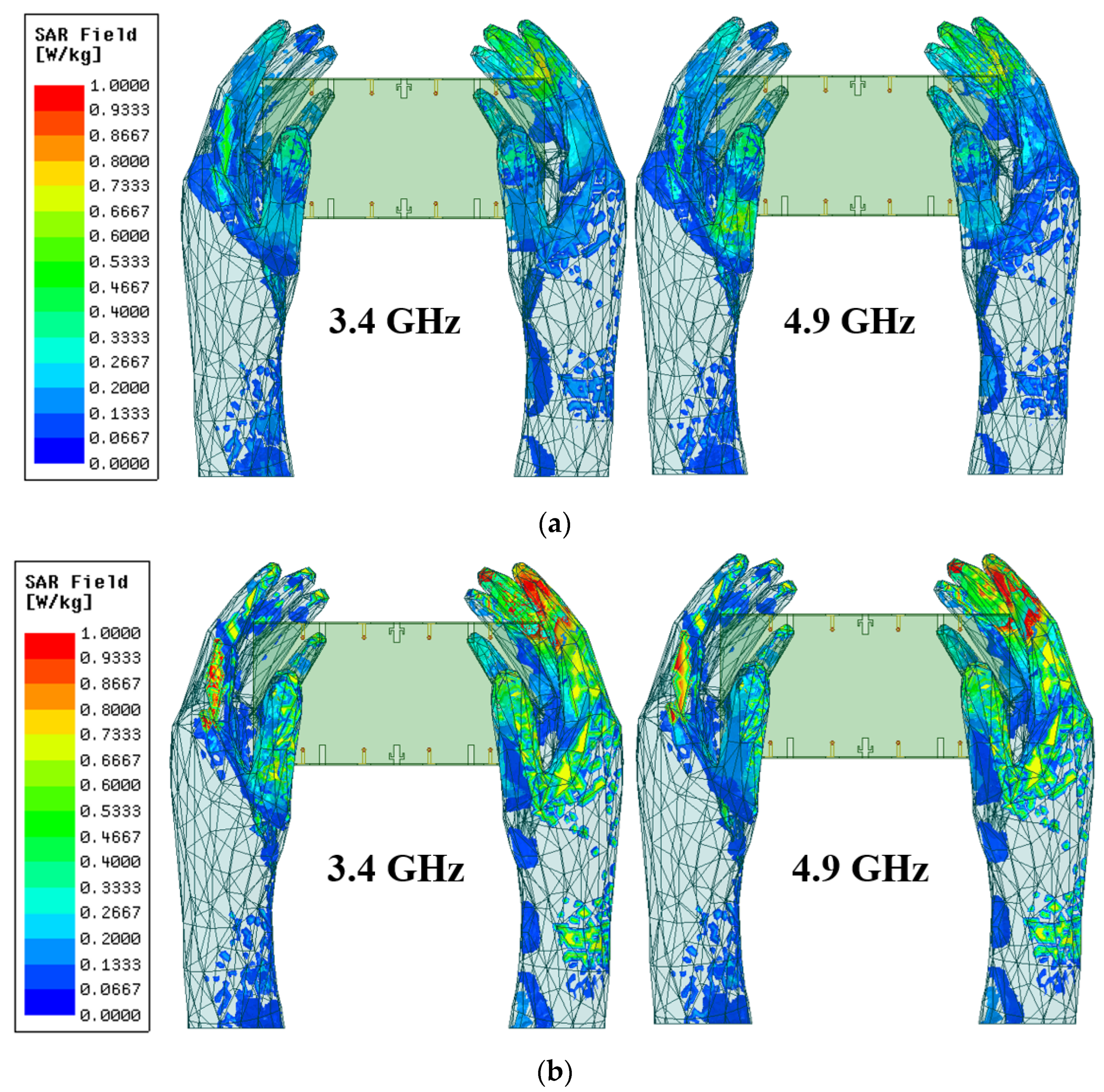
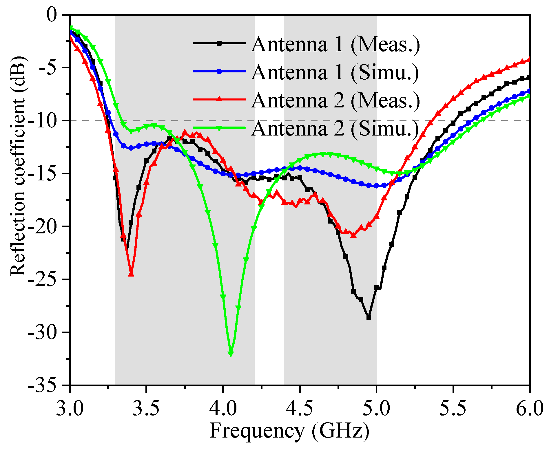
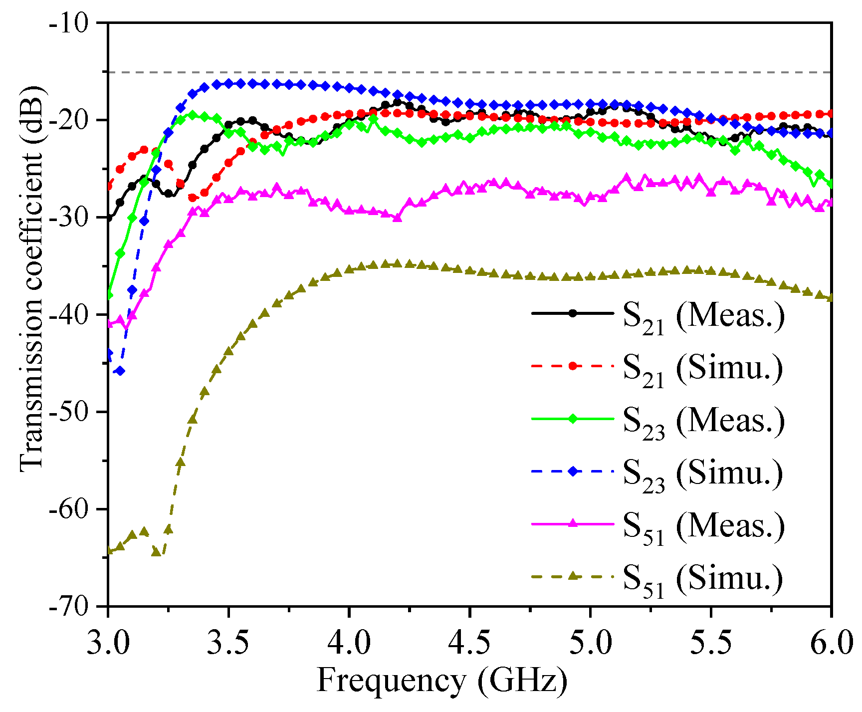
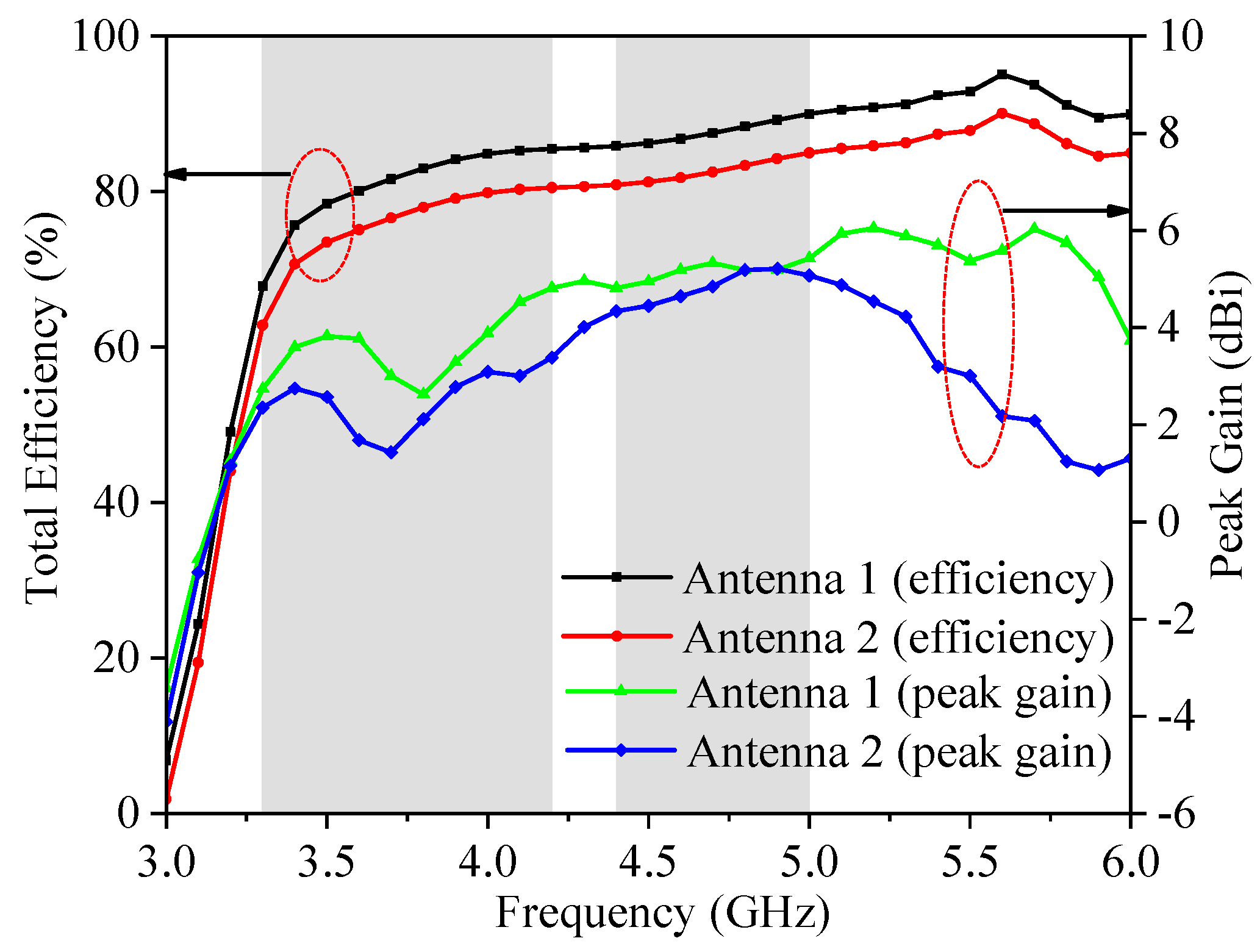
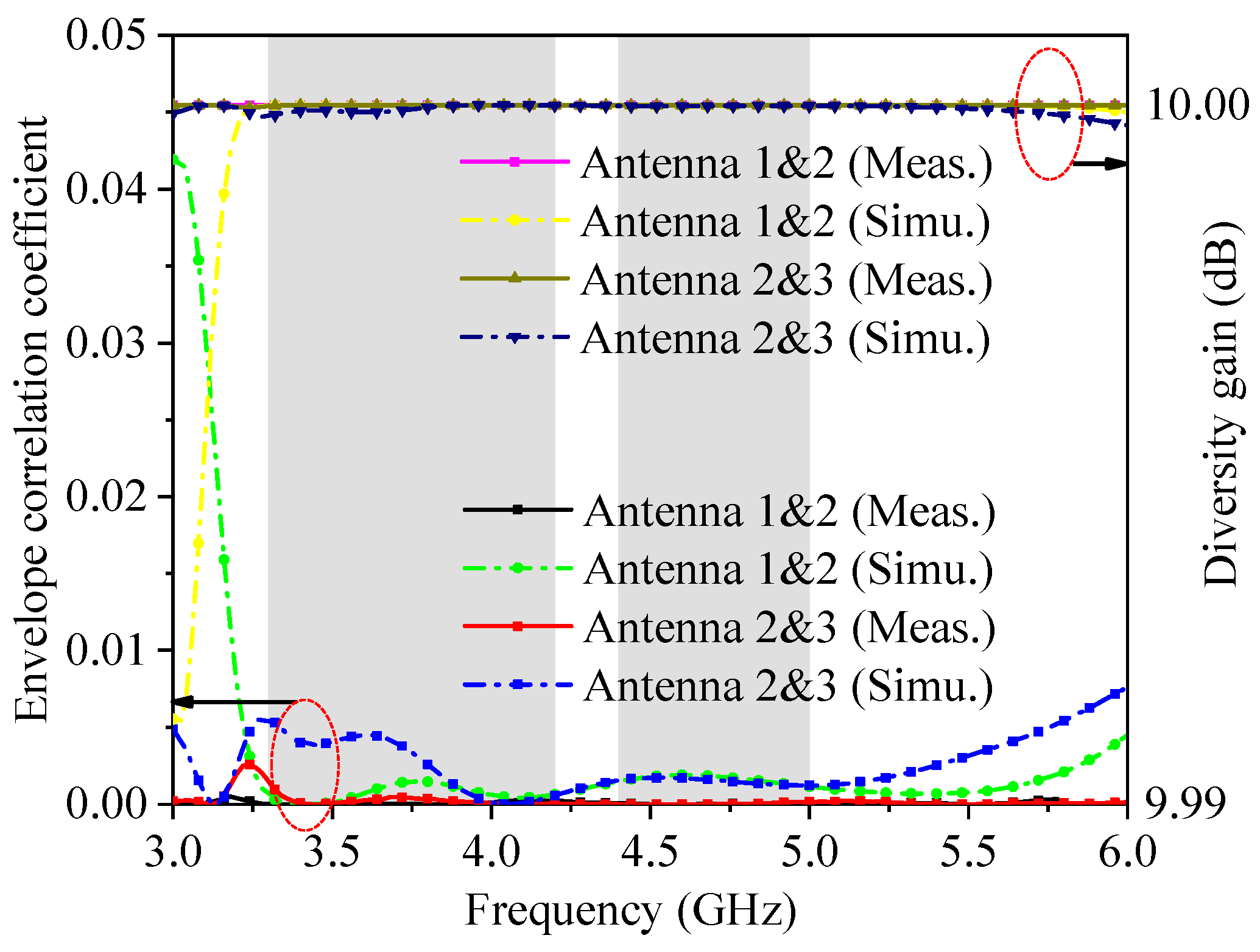
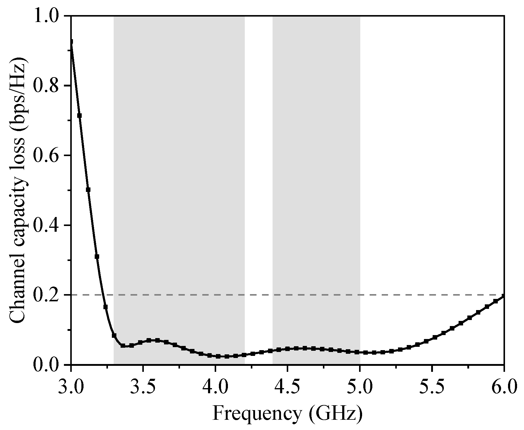
3. Measurement Results and Discussion

The photos of the produced antenna and the measurement setup are demonstrated in Figure 10. The S-parameters of the antenna are measured by the PNA N5224A network analyzer. The comparison of the measurement and the simulation is presented in Figure 11 and Figure 12. It shows that the −10 dB impendence band is 3.3–5.45 GHz. There is some deviation between the emulation and measurement results, which is mainly owing to the manufacturing error and the manual welding of the SMA connector. The values of the measurement results of the transmission coefficient surpass −15 dB in 3.3–5 GHz.
As shown in Figure 13, the results of measurement and simulation normalized radiation polarization of the displayed antenna at 3.4 GHz, and 4.9 GHz are proposed. A solid black line and a dotted green line represent the co-polarization and cross-polarization of measurement results, respectively. In addition, a red solid line and a dotted blue line express the co-polarization and cross-polarization of simulated results, respectively. The welding effect of the SMA connector may cause errors in the results of measurement and simulation.
In Figure 14, the measurement and simulation results of peak gain and radiating efficiency of the presented antenna are displayed. The median peak gain is about 3.5 dBi, and it can be seen that the curves of radiation efficiency and peak gain have similar trends. Moreover, the measured and simulated efficiency are higher than 75% in the desired wideband.
Calculated ECC and diversity gain (DG) are indicators to define the coupling effects and diversity of MIMO antenna systems. The calculated ECC can be expressed by far radiation field as Equation (1) [4]:
ECC = 4 π F 1 θ ,     F 2 θ , d Ω 4 π F 1   θ , 2 d Ω   4 π F 1   θ , 2 d Ω
The DG is calculated on the basis of Equation (2) [21]:
DG = 10   × 1 | ECC | 2
In Figure 15, the computed ECC and DG are presented, which are lower than 0.005 and higher than 9.99 dB in the desired wideband, respectively.
In the case of an ideal antenna system with a total antenna efficiency of 100% and zero correlation between antennas, the multiplexing efficiency (ME) represents the loss of power in the archetype antenna system when it is related to a specified capacity. The ME is presented in Equation (3) [21]:
ME = η 1 η 2 1 | ECC | 2
Channel capacity loss (CCL) indicates the rate of information transmitted within a communication channel without data loss. The values of CCL can be calculated by Equations (4)–(7) [9]:
C loss = log 2   ψ R
ψ R = ρ ii ρ ij ρ ji ρ jj
ρ ii = 1 -   S ii 2 -   S ij 2
ρ ij = - S ii * S ij + S ji * S ij   for   i , j = 1   or   2
The computed values of ME and CCL of the presented antenna are displayed in Figure 16 and Figure 17, which are better than 70% and smaller than 0.2 in 3.3–5 GHz.
Table 1 provides the operating frequency band, isolation, total efficiency, values of ECC, and measurement of a single antenna compared with other referenced antennas. It demonstrates that the isolation of the designed antenna is better than the antennas which are presented in [5,15,17,19,20], and the efficiency of the presented antenna is larger than that of the published designs illustrated in [1,5,17]. Finally, the designed antenna has lower ECC and is more compact than other published works.

4. Conclusions

A wideband eight-element is presented in this paper. This MIMO antenna includes eight elements made up of a C-shaped strip and two triangle-shaped strips to produce the frequency bands of 5G NR N77 and N79. The measured isolation is larger than 18 dB. The radiation efficiency and ECCs are higher than 75% and lower than 0.005, respectively. The designed eight-element wideband antenna is an agreeable choice for 5G NR smartphone applications.

Author Contributions

Conceptualization, J.C.; methodology, G.L.; data curation, J.Z. and S.X.; investigation, J.H.; writing—original draft preparation, J.C.; writing—review and editing, G.L.; supervision and funding acquisition, G.L. All authors have read and agreed to the published version of the manuscript.

Funding

This research work was partially funded by the National Natural Science Foundation of China under Grant No. 61671330, the Science and Technology Department of Zhejiang Province under Grant No. LGG19F010009, and Wenzhou Municipal Science and Technology Program under Grant No. C20170005 and No.2018ZG019.

Data Availability Statement

The data supporting this research article are available upon request to the corresponding author.

Conflicts of Interest

The authors declare that there is no conflicts of interests regarding the publication of this manuscript.

References

  1. Cheng, B.; Du, Z. Dual Polarization MIMO Antenna for 5G Mobile Phone Applications. IEEE Trans. Antennas Propag. 2021, 69, 4160–4165. [Google Scholar] [CrossRef]
  2. Dou, Y.; Dong, G.; Lin, J.; Cai, Q.; Liu, G. A Low Profile Dual-Band High Gain Directional Antenna for Anti-Interference WLAN Station Applications. Appl. Sci. 2021, 11, 2007–2013. [Google Scholar] [CrossRef]
  3. Dong, J.; Wang, S.; Mo, J. Design of a Twelve-Port MIMO Antenna System for Multi-Mode 4G/5G Smartphone Applications Based on Characteristic Mode Analysis. IEEE Access 2020, 8, 90751–90759. [Google Scholar] [CrossRef]
  4. Wang, H.; Zhang, R.; Luo, Y.; Yang, G. Compact Eight-Element Antenna Array for Triple-Band MIMO Operation in 5G Mobile Terminals. IEEE Access 2020, 8, 19433–19449. [Google Scholar] [CrossRef]
  5. Sim, C.-Y.-D.; Liu, H.-Y.; Huang, C.-J. Wideband MIMO Antenna Array Design for Future Mobile Devices Operating in the 5G NR Frequency Bands n77/n78/n79 and LTE Band 46. IEEE Antennas Wirel. Propag. Lett. 2020, 19, 74–78. [Google Scholar] [CrossRef]
  6. Khan, J.; Ullah, S.; Tahir, F.A.; Tubbal, F.; Raad, R. A Sub-6 GHz MIMO Antenna Array for 5G Wireless Terminals. Electronics 2021, 10, 3062–3076. [Google Scholar] [CrossRef]
  7. Xu, H.; Wang, G.; Qi, M.; Zeng, H. Ultra-small single-negative electric metamaterials for electromagnetic coupling reduction of microstrip antenna array. Opt. Express 2012, 20, 21968–21976. [Google Scholar] [CrossRef]
  8. Xu, H.; Wang, G.; Qi, M. Hilbert-Shaped Magnetic Waveguided Metamaterials for Electromagnetic Coupling Reduction of Microstrip Antenna Array. IEEE Trans. Magn. 2013, 49, 1526–1529. [Google Scholar] [CrossRef]
  9. Han, C.-Z.; Xiao, L.; Chen, Z.; Yuan, T. Co-Located Self-Neutralized Handset Antenna Pairs with Complementary Radiation Patterns for 5G MIMO Applications. IEEE Access 2020, 8, 73151–73163. [Google Scholar] [CrossRef]
  10. Muhsin, M.; Salim, A.; Ali, J. A Compact Self-Isolated MIMO Antenna System for 5G Mobile Terminals. Comput. Syst. Sci. Eng. 2022, 42, 919–934. [Google Scholar] [CrossRef]
  11. Alharbi, A.; Kulkarni, J.; Desai, A.; Sim, C.; Poddar, A. A Multi-Slot Two-Antenna MIMO with High Isolation for Sub-6 GHz 5G/IEEE802.11ac/ax/C-Band/X-Band Wireless and Satellite Applications. Electronics 2022, 11, 473–494. [Google Scholar] [CrossRef]
  12. Yang, R.; Xi, S.; Cai, Q.; Chen, Z.; Wang, X.; Liu, G. A Compact Planar Dual-Band Multiple-Input and Multiple-Output Antenna with High Isolation for 5G and 4G Applications. Micromachines 2021, 12, 544–551. [Google Scholar] [CrossRef] [PubMed]
  13. Zhu, H.; Guan, X.; Ren, B.; Wang, C. Dual-Band Eight-Element MIMO Antenna Consisted of Tightly Arranged Hybrid Antenna Pairs for 5G Smartphone. Int. J. RF Microw. Comput. Aided Eng. 2021, 31, 22886–22896. [Google Scholar] [CrossRef]
  14. Liu, X.; Zhang, J.; Xi, H.; Yang, X.; Sun, L.; Gan, L. A Compact Four-Band High-Isolation Quad-Port MIMO Antenna for 5G and WLAN Applications. AEU Int. J. Electron. Commun. 2022, 153, 154294. [Google Scholar] [CrossRef]
  15. Wong, K.; Chang, H.; Chen, j.; Wang, K. Three Wideband Monopolar Patch Antennas in a Y-Shape Structure for 5G Multi-Input–Multi-Output Access Points. IEEE Antennas and Wirel. Propag. Lett. 2020, 19, 393–397. [Google Scholar] [CrossRef]
  16. Sghaier, N.; Latrach, L. Design and Analysis of Wideband MIMO Antenna Arrays for 5G Smartphone Application. Int. J. Microw. Wirel. Technol. 2022, 14, 511–523. [Google Scholar] [CrossRef]
  17. Hei, Y.; He, J.; Li, W. Wideband Decoupled 8-Element MIMO Antenna for 5G Mobile Terminal Applications. IEEE Antennas Wirel. Propag. Lett. 2021, 20, 1448–1452. [Google Scholar] [CrossRef]
  18. Jaglan, N.; Gupta, S.; Sharawi, M. 18 Element Massive MIMO/Diversity 5G Smartphones Antenna Design for Sub-6 GHz LTE Bands 42/43 Applications. IEEE Open J. Antennas Propag. 2021, 2, 533–545. [Google Scholar] [CrossRef]
  19. Xi, L. A Wideband Planar Filtering Dipole Antenna for 5G Communication Applications. Microw. Opt. Technol. Lett. 2019, 61, 2746–2751. [Google Scholar] [CrossRef]
  20. Sun, L.; Li, Y.; Zhang, Z.; Feng, Z. Wideband 5G MIMO Antenna with Integrated Orthogonal-Mode Dual-Antenna Pairs for Metal-Rimmed Smartphones. IEEE Trans. Antennas Propag. 2020, 68, 2494–2503. [Google Scholar] [CrossRef]
  21. Roshani, S.; Yahya, S.; Alaneri, B.; Mezaal, Y.; Liu, L.; Roshani, S. Filtering Power Divider Design Using Resonant LC Branches for 5G Low-Band Applications. Sustainability 2022, 14, 12304. [Google Scholar] [CrossRef]
  22. Al-khaylani, H.; Elwi, T.; Ibrahim, A. Optically Remote Control of Miniaturized 3D Reconfigurable CRLH Printed Self-Powered MIMO Antenna Array for 5G Applications. Micromachines 2022, 13, 2061–2077. [Google Scholar] [CrossRef]
  23. Huang, J.; Chen, Z.; Cai, Q.; Loh, T.; Liu, G. Minimized Triple-Band Eight-Element Antenna Array for 5G Metal-frame Smartphone Applications. Micromachines 2022, 13, 136–146. [Google Scholar] [CrossRef] [PubMed]
Figure 1. Composition and size of the presented wideband MIMO antenna (Unit: millimeters). (a) front view; (b) side view.
Applsci 13 00137 g001
Figure 2. Design development and S-parameters of antenna unit: (a) the design evolution; (b) simulated S11.
Applsci 13 00137 g002
Figure 3. Simulated surface current distribution at (a) 3.4 GHz; (b) 4.9 GHz.
Applsci 13 00137 g003
Figure 4. The simulation results of S11 with unequal values of (a) W; (b) H.
Applsci 13 00137 g004
Figure 5. The simulated transmission coefficients of the designed antenna with/without isolation structure.
Applsci 13 00137 g005
Figure 6. The simulation results of the reflection coefficients of the presented antenna in DHM.
Applsci 13 00137 g006
Figure 7. The simulated transmission coefficients of the designed antenna in DHM.
Applsci 13 00137 g007
Figure 8. The simulated 3D radiation pictures of (a) Ant. 3 and Ant. 4 operate at 3.4 GHz; (b) Ant. 3 and Ant. 4 operate at 4.9 GHz.
Applsci 13 00137 g008
Figure 9. The simulation results of SAR field distribution of (a) Ant. 3; (b) Ant. 4.
Applsci 13 00137 g009
Figure 10. The portraiture of setup for measurements: (a) fabricated antenna; (b) vector network analyzer; (c) anechoic chamber.
Applsci 13 00137 g010
Figure 11. The measurement and simulation results of the reflection coefficients of the antenna.
Applsci 13 00137 g011
Figure 12. The measurement and simulation results of transmission coefficients of the presented antenna.
Applsci 13 00137 g012
Figure 13. Measured and simulated 2D radiation charts of (a) E-plane at 3.4 GHz; (b) H-plane at 3.4 GHz; (c) E-plane at 4.9 GHz; (d) H-plane at 4.9 GHz.
Applsci 13 00137 g013
Figure 14. Measured peak gain and total efficiency of the designed antenna.
Applsci 13 00137 g014
Figure 15. Computed ECC and DG of the designed antenna.
Applsci 13 00137 g015
Figure 16. Computed ME of the designed antenna.
Applsci 13 00137 g016
Figure 17. Computed CCL of the designed antenna.
Applsci 13 00137 g017
Table 1. Performance comparison of the designed antenna with other published antennas.
ReferenceOperating Band (GHz)Isolation (dB)Total Efficiency (%)ECCSize (mm3)
[1]4.37–5.5<−2240–50<0.06815.6 × 15.6 × 1.6
[5]3.25–5.93<−1041–69<0.113.9 × 7 × 0.8
[15]3.3–4.2<−10.563.1–85.1<0.330 × 7.5 × 2
[17]3.3–5.95<−1547–78<0.1117 × 6 × 0.8
[19]3.08–5.15<−10--39.75 × 10.5 × 1
[20]3.3–5<−1231.6–88.6<0.1140 × 3 × 7.5
Pro.3.3–5.45<−18>75<0.0056.8 × 7 × 0.8
Disclaimer/Publisher’s Note: The statements, opinions and data contained in all publications are solely those of the individual author(s) and contributor(s) and not of MDPI and/or the editor(s). MDPI and/or the editor(s) disclaim responsibility for any injury to people or property resulting from any ideas, methods, instructions or products referred to in the content.

