Article

Research on Mechanical Characteristics of Slope Reinforcement by Spatial Arc Crown Beam Composite Supporting Structure

1
School of Architecture and Civil Engineering, Xi’an University of Science and Technology, Xi’an 710054, China
2
Plie-Supported Structures Research and Test Center, Xi’an University of Science and Technology, Xi’an 710054, China
3
School of Civil Engineering, Harbin Institute of Technology, Harbin 150001, China
*
Author to whom correspondence should be addressed.
Appl. Sci. 2023, 13(1), 293; https://doi.org/10.3390/app13010293
Submission received: 26 November 2022 / Revised: 20 December 2022 / Accepted: 21 December 2022 / Published: 26 December 2022
(This article belongs to the Section Civil Engineering)

Abstract

:
To effectively optimize the mechanical behavior of a traditional anti-slide pile and reduce environmental destruction, a new method for slope reinforcement by a spatial arc crown beam composite supporting structure was proposed. First, a numerical model was validated through lab-scale model test data obtained herein, and then a full-scale numerical model was created for an in-depth understanding of the distribution regularity of displacement along the pile, the soil pressure, the crown beam stiffness, and so on. The results demonstrated that: (1) The spatial arc crown beam is simplified to a two-hinged arch, and the maximum value of the bending moment in the arc crown beam is about one-third of the straight crown beam through theoretical calculation. (2) The spatial arc crown beam redistributes the load sharing among different piles, and the extreme bending moment of other piles varies within 10% along the downhill direction except for the piles at the slope foot. (3) Bending moments are close to zero at the pile end, and the anti-slide pile can be simplified as a vertical beam with one end fixed and the other end hinged. (4) The axial force in the spatial arc crown beam is always presented as pressure, so the crown beam can make full utilization of the compression resistance of concrete. (5) The distribution characteristic of soil pressure in front of the pile at the arch foot is different from that in other positions, and the stable soil at the slope foot provides greater soil resistance for anti-piles. (6) As the crown beam stiffness is above five times the reference value, the axial force of the crown beam tends to be stable, and as the crown beam stiffness increases continually, the maximum value of My is −1013.13 kN·m, and the constraining effect of the crown beam is gradually weakened.

1. Introduction

As one of the most common natural disasters worldwide, landslides are mainly caused by human engineering construction and natural environmental factors. Frequent landslide disasters in recent years have resulted in enormous losses to lives and properties. When it comes to landslide treatment, anti-slide piles can penetrate the landslide bed to resist landslide mass and keep a slope stable, which works as a widespread measure against landslides [1,2]. As for research on slope reinforcement by a traditional single-row pile-supporting structure, many domestic and foreign scholars have analyzed the influence of pile layout, pile spacing, and geotechnical properties upon slope stability and acquired a great number of research findings [3,4,5,6]. Qiu et al. [7] theoretically derived a formula for pile-spacing calculation under an equilibrium condition that the side friction of the pile was equivalent to the landslide thrust between piles. Xiao proposed a method to calculate the pile top burial depth through the ultimate balance theory, derived the calculation formula through the transfer coefficient method, and validated the formula [8]. However, single-row piles exert a limited effect on slope reinforcement during practical engineering applications, and in particular, double-row and even the multi-row piles are often adopted for medium- or large-sized landslide treatment. Xiao et al. [9] put forward a new layout of double-row piles, with the top of the back-row piles embedded in the slope at a certain depth, and the top of the front-row piles was placed on the slope surface. Lei et al. [10] researched the difference in slope reinforcement between double- and the single-row piles and indicated that their failure modes were significantly different. Li et al. [11] proposed a simplified model of double-row piles to analyze the influence from the shear strength of soil on the slope stability under a seismic effect. Shen et al. [12] analyzed the mechanical transfer effect between double-row piles and proposed a calculation method to distribute the landslide thrust among different piles. Based on the particle image velocity (PIV) measurement and image-processing technology, Xie et al. [13] advised that the row spacing of double-row piles should be three to five times the pile diameter, and that the pile spacing should be four times the pile diameter. It can thus be seen that the theoretical research on and the engineering applications of both single-row and multi-row piles are relatively sufficient. However, in view of slope stability and other factors, slope reinforcement through single-row and multiple-row anti-slide piles is largely limited, so as to avoid soil excavation in a large area.
The landslide thrust is mainly carried by the upper part of a pile. In order to optimize the mechanical behavior of single-row and the multiple-row piles, the pile top can be formed as a whole by a straight crown beam made of concrete, which can substantially improve slope stability. In particular, the upper part of the pile body should be further strengthened under a seismic effect [14,15]. Zhou showed that the pile top displacement of front-row piles in a portal frame composite structure was significantly smaller than that of single-row cantilever piles and crown beam-free double-row piles [16]. Some scholars indicated that the crown beam plays a significant role in coordinating the deformation of anti-slip piles, and the back-row piles had a greater impact on slope stability than the front-row piles [17,18]. Reliability and economic efficiency are two important factors for portal frame composite structure, and excessively large pile spacing and crown beam size leads to the failure in the slope reinforced by anti-slide piles, which may weaken the soil arching effect [19,20,21].
Because of the mechanical characteristics of the arched beam, the compression resistance of concrete can be given full play by an arched beam instead of a traditional straight crown beam. At present, such a construction technique has been widely applied in subway engineering [22,23], but there is relatively little research on the application of the arched beam in landslide treatment. According to Luo et al. [24], the mechanical behavior of a composite structure was more reasonable when the arched beam structure to serve as the crown beam in the slope reinforcement. Zhang and Deng [25] illustrated that an arched beam could transfer partial landslide thrust into the stable soil mass at both sides of the sliding mass, so an arched beam has obvious advantages over a straight crown beam. Zhang et al. [26] verified that the concrete strength of the arched beam had a significant effect on slope stability, but as the concrete strength increased, to a certain extent, the strengthening effect on the slope was no longer obvious. Chen et al. [27] reported that the arched beam effectively bore the landslide thrust under a seismic effect and had a significant effect on controlling slope deformation. However, all of the arched beams in the above research were arranged in a plan or elevation form. A large amount of slope soil was excavated during the construction process, but the orographic factor concerning the slope has not been fully considered.
In summary, according to domestic and foreign research, a new method of slope reinforcement by a spatial arc crown beam composite supporting structure is proposed herein. Anti-slide piles were arranged along the slope surface and at the slope foot; all pile tops were connected through the arc crown beam along the slope surface. The projection of the crown beam was arc-shaped on the horizontal plane. References are provided herein for the design and engineering of slope reinforcement through a laboratory model test and numerical simulation.

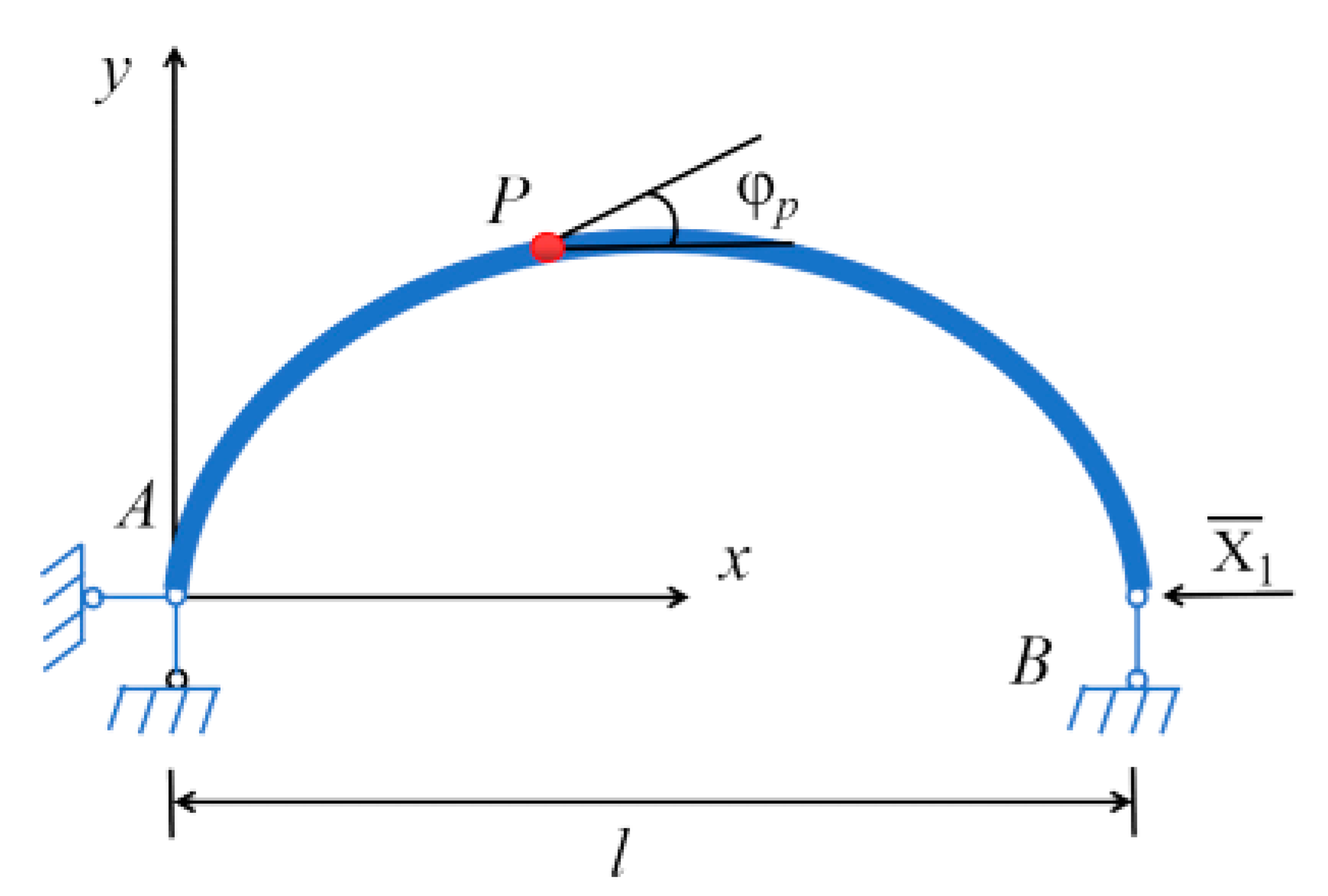
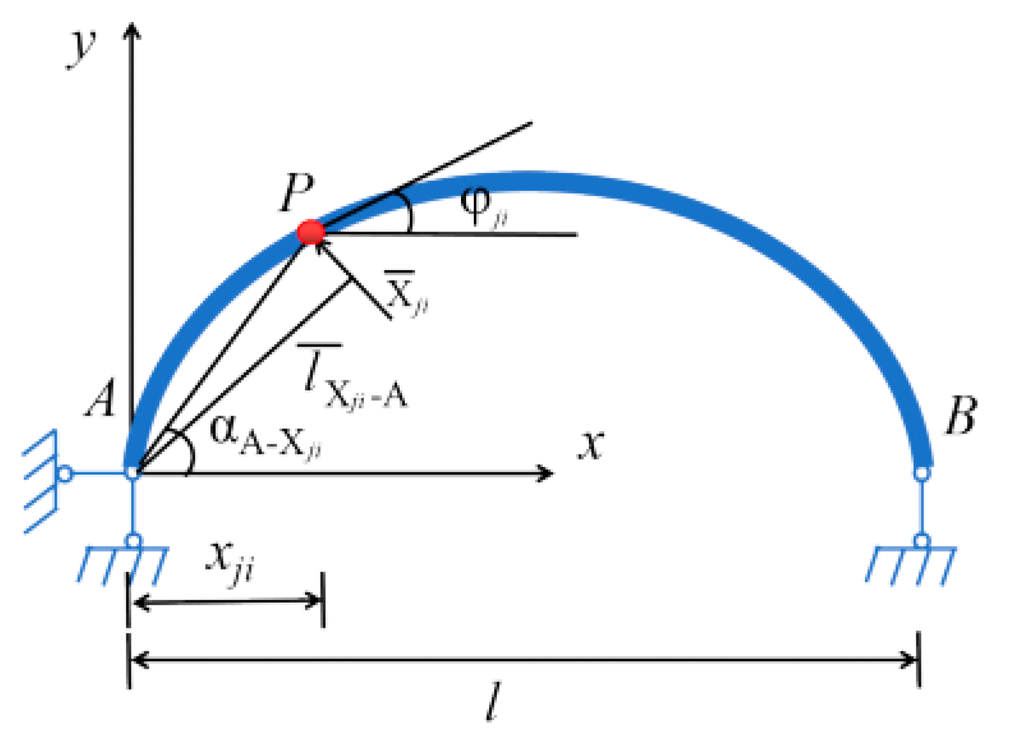
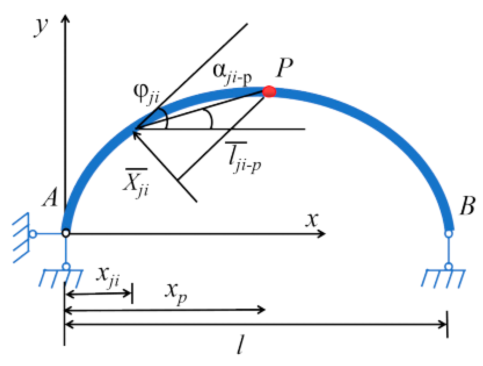
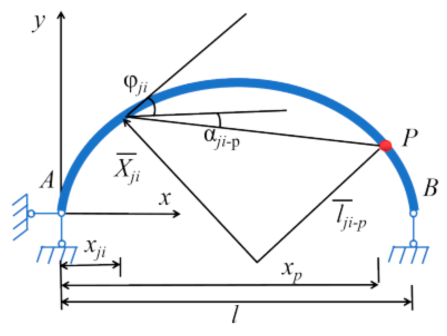
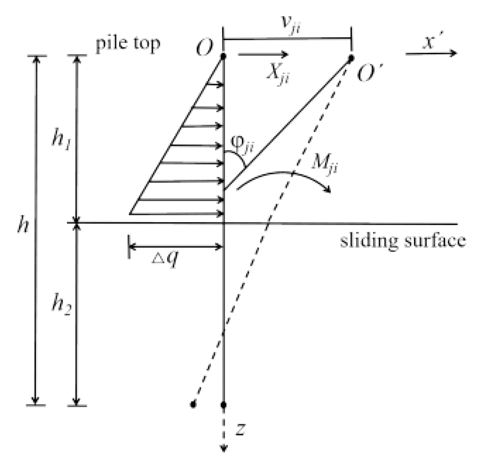
2. Theoretical Analysis

All pile tops are connected by an inclined arc crown beam along the slope surface, which is projected to the horizontal plane but still regarded as the arc beam for the convenience of calculation. The calculation mode can be simplified to a two-hinged arch in light of the research findings and the security of calculation results [28,29]; only the interactive radial horizontal concentrated force between the pile top and the crown beam was regarded as the redundant force. Additionally, the horizontal thrust at the arch foot and the radial horizontal concentrated force were regarded as the redundant force. However, the bending moment and the torsional moment between the pile top and the crown beam were not considered. In this study, the acting force between the anti-slip pile and the crown beam was taken as the redundant force, and then calculation models of the crown beam and anti-slip pile were established, respectively. At the same time, the internal force of the crown beam and the displacement of the anti-slip pile were analyzed theoretically. According to the displacement coordination condition of the connection between the crown beam and the pile top, the typical equations were presented to solve the redundancy force, and then the bending moment and axial force of the crown beam were calculated.
More detailed calculations can be found in a previous study [25], which were analyzed as follows. The arc crown beam was divided into two parts for the calculation model of a two-hinged arch. The basic system with the horizontal thrust ( X ¯ 1 = 1 ) at the arch foot was taken as the redundant constraint, as shown in Figure 1. The bending moment ( M ¯ p 1 ), the shear force ( Q ¯ p 1 ), and the axial force ( N ¯ p 1 ) at an arbitrary point p of the crown beam are expressed by Equations (1)–(3):
M ¯ p 1 = y p
Q ¯ p 1 = sin φ p
N ¯ p 1 = cos φ p
where yp is the abscissa of point p; φ p is the tangent azimuth angle of point p.
However, the radial horizontal force ( X ¯ j i = 1 ) acts alone on the crown beam. The left half span and the right half span need to be calculated separately according to the position of the radial horizontal force. The radial horizontal force is applied on the left half span of the crown beam, as shown in Figure 2. Only the left half span of the crown beam was taken as an instance for analysis during the theoretical calculation process. l ¯ X j i A is the moment arm of X ¯ j i on the left support A, and it can be expressed by Equation (4). The vertical support reaction at position A and B can be calculated, respectively, as shown in Equations (5) and (6). The horizontal support reaction at position A is calculated using Equation (7).
l ¯ X ¯ j i A = x j i cos ( α A X ¯ j i φ j i ) cos α A X ¯ j i
Y ¯ A = Y ¯ B X ¯ j i cos φ j i
Y ¯ B = X ¯ j i l ¯ X ¯ j i A l
X ¯ A = X ¯ j i sin φ j i
where x j i is an abscissa of acting point p; α A X ¯ j i is the plane-coordinate azimuth of the left support A from an acting point p; φ j i is the tangent azimuth angle; X ¯ j i is the radial horizontal concentrated force; l is the span.
With no consideration of the influence from the horizontal support reaction, Equations (8) and (9) show the bending moment ( M ¯ p j i 0 ) and the shear force ( Q ¯ p j i 0 ) at an arbitrary point p of the crown beam within an interval of 0 ≤ xxji.
M ¯ p j i 0 = Y ¯ A x p
Q ¯ p j i 0 = Y ¯ A
where xp is the abscissa of point p.
Considering the influence of horizontal support reaction, the bending moment ( M ¯ p j i ), the shear force ( Q ¯ p j i ), and the axial force ( N ¯ p j i ) at an arbitrary point p of the crown beam within the interval of 0 ≤ xxji are expressed by Equations (10)–(12).
M ¯ p j i = M ¯ p j i 0 X ¯ A y p
Q ¯ p j i = Q ¯ p j i 0 cos φ p X ¯ j i 0 sin φ p
N ¯ p j i = Q ¯ p j i 0 sin φ p + X ¯ j i 0 cos φ p
where X ¯ j i 0 is the horizontal internal force along the x-axis direction at an arbitrary point p of the crown beam, and X ¯ j i 0 = X ¯ A .
The interval of x j i x l was discussed with no consideration of the influence from the horizontal force of support. l ¯ j i p is the moment arm of Xji on the arbitrary point p in the crown beam. According to Figure 3 and Figure 4, there are two cases for l ¯ j i p during the calculation process, which can be expressed by Equation (13). The bending moment and the shear force at an arbitrary point p of a crown beam within the interval are presented in Equations (14) and (15):
l ¯ j i p = ( x p x j i ) sin ( π 2 φ ji + α j i - p ) cos α j i - p
M p j i 0 = Y ¯ A x p + X ¯ j i + l ¯ j i p
Q p j i 0 = Y ¯ B
According to the calculation results of Equations (14) and (15), the internal force of the crown beam is calculated within the interval of 0 ≤ xxji by Equations (10)–(12). In the same way, the right half span of the crown beam is analyzed.
In the theoretical analysis, it was assumed that the sliding surface and landslide thrust remain constant. The sliding force was decomposed along the radial and tangential direction of the arc crown beam. Without consideration of the friction force between the anti-pile and the soil, the pile was designed as a beam on an elastic foundation, and the calculation mode of the anti-slide pile is presented in Figure 5. The x’-axis direction is the radial direction of the arc crown beam, and the internal force and the displacement of the anti-slide pile were calculated by the “m-k” method [30].
Where Xji is the redundant force; Δq is the maximum landslide thrust; h1 is the length of the anti-slide pile affected by the load; h2 is the anti-slide length of the anchorage section; φ j i is the tangent azimuth angle; v j i is the displacement of the anti-slide pile; Mji is the bending moment of the pile.
Based on the constraint at the pile bottom, the calculation method of the elastic pile was adopted. Only the displacement of the pile top along the radial direction of the arc crown beam was considered. The pile top displacement is expressed as Equation (16) [25]:
v j i = A X j i + B Δ q
A = 1 α 3 E I B 8 D 7 D 8 B 7 A 8 B 7 B 8 A 7
B = b α 5 E I h 1 B 8 F 7 F 8 B 7 A 8 B 7 B 8 A 7
where Xji is the redundant force; Δq is the maximum landslide thrust; α is the horizontal deformation coefficient of the pile; EI is the flexural rigidity of pile; Ai, Bi, Di, and Fi are the coefficient for the combined value of both the “m” method and the “k” method.
The pile top displacement was calculated according to the redundant force of the pile top and landslide thrust. The equation flexibility of the composite structure is established as Equation (19) by the displacement coordination condition at the connection between the arc crown beam and the pile top. More details on these calculations can be found elsewhere [31].
δ 11 X 1 + δ 12 X j 2 + + δ 1 n X j n = 0 δ i 1 X 1 + δ i 2 X j 2 + + δ i n X j n = v j i δ n 1 X 1 + δ n 2 X j 2 + + δ n n X j n = v j n
where δ is the flexibility coefficient matrix; X is the redundancy force matrix at the connection between the arc crown beam and the pile top; v is the pile top displacement matrix.
According to this method, in view of the data concerning a landslide project [25], the arc crown beam composite supporting structure was compared with the straight crown beam. The maximum value of bending moments of the straight and arc crown beams were 9.8 MN·m and 3.4 MN·m through a simplified calculation formula, respectively. The maximum bending moment of the arc crown beam was about one third that of the straight crown beam. This proved that the mechanical performance of the arc crown beam was reasonable in the composite structure. However, the theoretical calculation was based on the assumed condition, so there was a certain bias in the result. The slope reinforcement by the spatial arc crown beam composite supporting structure was further analyzed herein through a laboratory model test and numerical simulation.

3. Laboratory Model Test
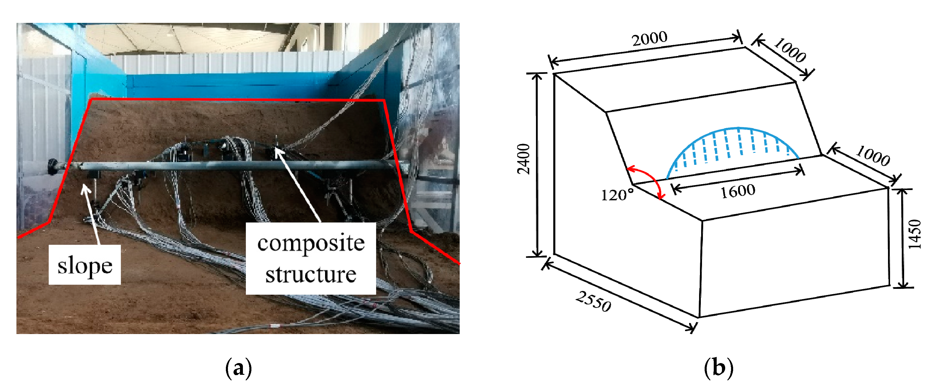
3.1. Test Design

A slope project located in the Yan’an City of Shaanxi Province was taken as the prototype for the laboratory model test. The geometric dimensions were 25.5 m (Length) × 20 m (width) × 24 m (height), and the slope angle was 60°. Given the size of the laboratory model test, the similarity ratio scale model test was established based on similarity theory, so as to minimize its economic cost and test period and to avoid any limits due to field conditions. The similarity ratio of the laboratory model test was 1:10. The similarity ratio of those main parameters involved are listed in Table 1, and the geometric dimensions of the slope model for the laboratory model test are shown in Figure 6. The geometric dimensions of the model box for the laboratory model test are used herein with dimensions of 6.0 m (length) × 2.2 m (width) × 2.8 m (height).

3.2. Test Materials

The natural undisturbed soil from the Xi’an City of Shaanxi Province was used in the laboratory model test. Screened fine-grained soil less than 2 mm was adopted herein in the case of the influence from gravel, coarse-grained soil, and weeds upon soil compaction and load transfer. According to the calculation, the unit soil weight was 20.8 kN/m3; the cohesion was 42.5 kPa; the internal friction angle was 30.05°; and the moisture content was 18%.
The model material should be easy to collect and process. At the same time, given the material homogeneity and mechanical property stability, the model piles and crown beam were made of a stainless steel rectangular tube, whose sectional geometric dimensions were 40 mm (length) × 30 mm (width) and 30 mm (length) × 15 mm (width), respectively. The elastic modulus of the model pile was 190 GPa; the length of each pile is listed in Table 2. The piles at both sides of the composite structure were arranged at the slope foot, and the rest of the piles were arranged on the slope surface. The top of each pile was connected as a whole through the arc crown beam, as shown in Figure 7.

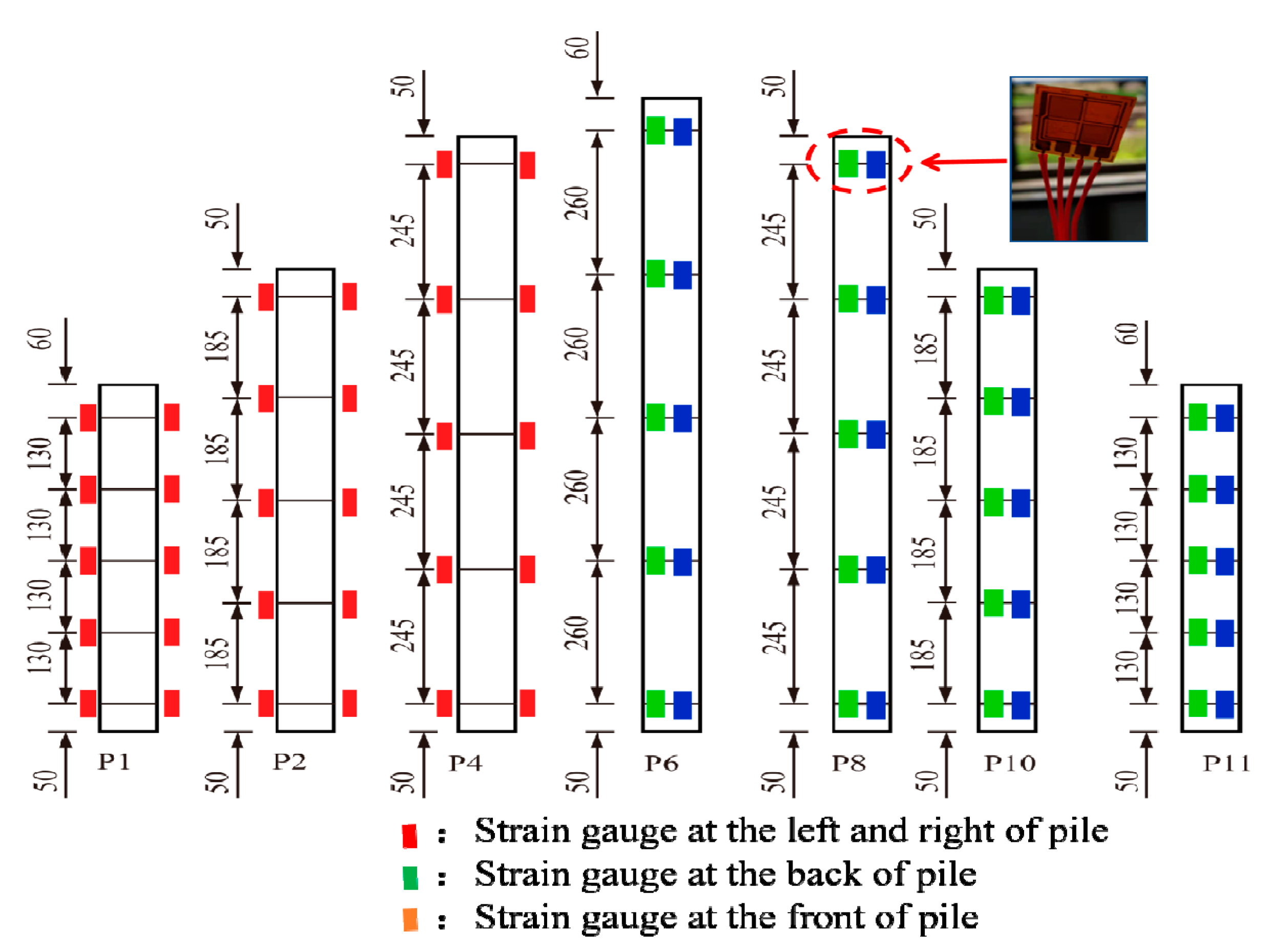
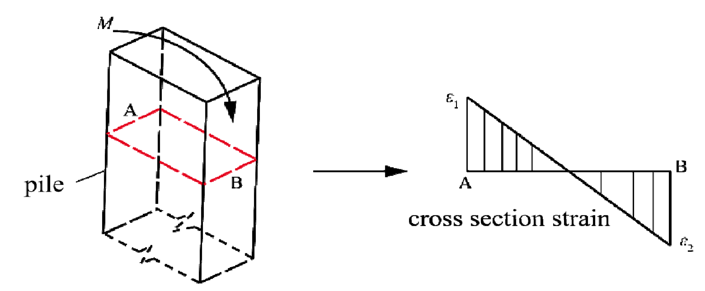
3.3. Test Arrangement and Loading

In order to analyze the variation regularity of the bending moment along the pile, the strain was measured by a strain gauge. Some piles were selected as research objects due to the limited test conditions and in light of the geometric axial symmetry of the composite structure. The strain gauges were arranged symmetrically on the left and right sides of P1, P2, and P4 and the front and rear sides of P6, P8, P10, and P11 from the top to the bottom, as shown in Figure 8. The data were recorded by the TST3826E static strain tester with a resolution ratio of 1.0 × 10⁻⁶ and a maximum data acquisition frequency of 50 Hz; the resistance value of the strain gauge was 1000 ± 0.1 Ω, and the sensitivity coefficient was 2.15 ± 1%.
The model piles were placed and fixed at a designated position in the laboratory model test. The soil was back-filled to the predetermined pile height and then tamped layer by layer. The compaction degree was not less than 0.9. The concrete slab was used as a load at the test site. The physical dimensions were length × width × thickness = 2.0 m × 1.0 m × 0.12 m. Each concrete slab carried a load of 3 kPa and served as one level of load. There were five levels of load in total. When each level of load was applied, and when the static strain tester showed that the strain value was basically in a stable position, the next level of load could be applied.

3.4. Test Results

The slope was reinforced by the spatial arc crown beam composite supporting structure. When the load was applied on the slope top, the pile generated a bending moment both along the downhill and the transverse slope direction. The sectional bending moment of the pile was calculated based on the data collected through strain gauges. The calculation formula can be expressed in Equation (20). The direction of the pile bending moment was defined according to the coordinate system and concerning the right-hand rule, as shown in Figure 9.
M = E I ( ε 1 ε 2 ) / h
where M is the bending moment of the pile, N·m; E is the elasticity modulus, MPa; I is the second moment of area, m4; ε 1 and ε 2 are the sectional strains at the pile top and pile end, respectively; h is the sectional height, m.

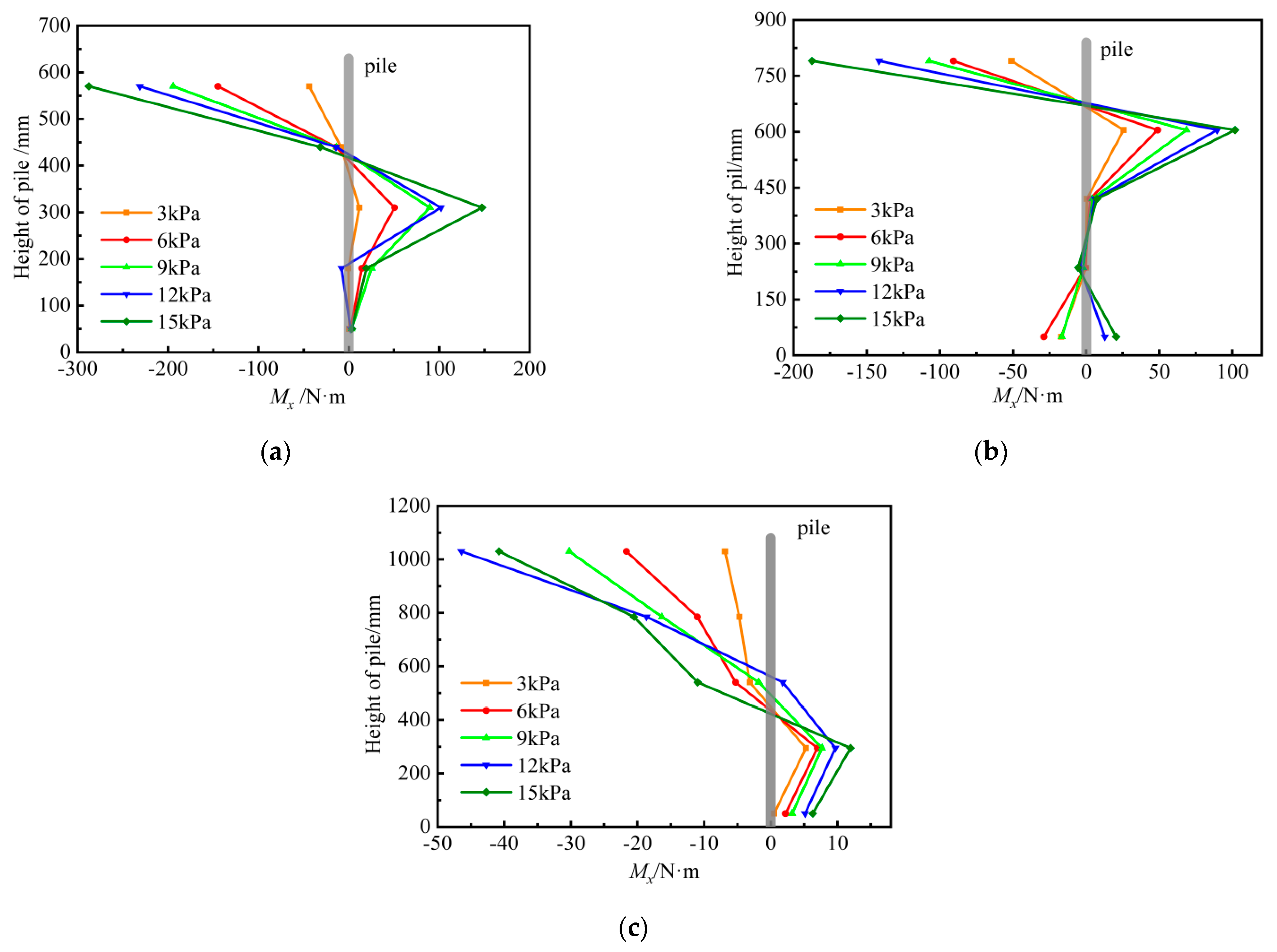
3.4.1. Bending Moment of Pile along the Transverse Slope Direction (Mx)

Under the different levels of load at the slope top, P1, P2, and P4 generated the bending moment along the transverse slope direction, as shown in Figure 10. Thus, the distribution regularity of Mx was basically the same in the spatial arc crown beam composite supporting structure. First, the contraflexure point appeared at the upper part of the pile, and the value of Mx at the pile top was the largest. Additionally, the increasing bending moment at the pile top close to the arch foot shows that the landslide thrust along the transverse slope direction is transmitted from the middle pile (P6) to the side piles (P1, P11) through the crown beam. Under the fifth level of load, the maximum bending moments of P1, P2, and P4 were −287.58 N·m, −187.36 N·m, and −40.76 N·m, respectively. However, the minimum bending moments appeared at the pile end, namely, 7.58 N·m, 18.36 N·m, and 5.76 N·m, respectively. The bending moments were so small that they could be regarded as zero. The variation in Mx at the pile end was low as the load applied on the slope top increased from the first to the fifth level. However, the extreme values of both positive and negative bending moments increased significantly. Specifically, the negative bending moments increased by 4.56, 2.68, and 4.95 times, and the positive bending moments increased by 11.76, 2.96, and 1.27 times, respectively. All piles were connected as a whole by the arc crown beam, and the load transmitted to the pile by the crown beam had little impact on the pile end. Actually, it was the middle-upper part of the pile that bore most of the load. The piles at the slope foot played the role of the arch foot. This indirectly confirms that the soil resistance of the lower part of the pile is larger. The crown beam always shows compression resistance under different levels of load, which gives full play to the advantage of concrete and thus avoids the bending–shear failure of a straight crown beam.

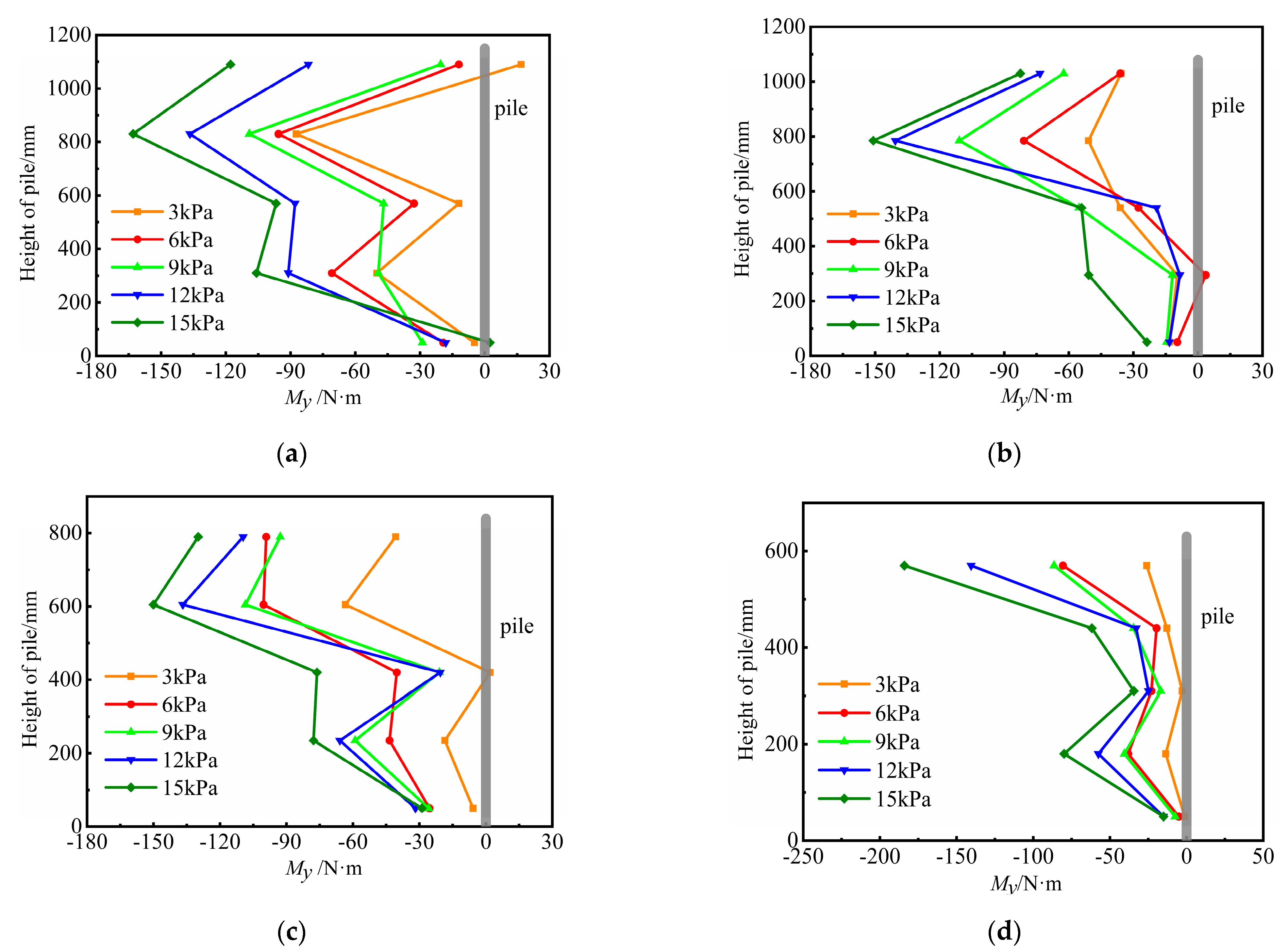
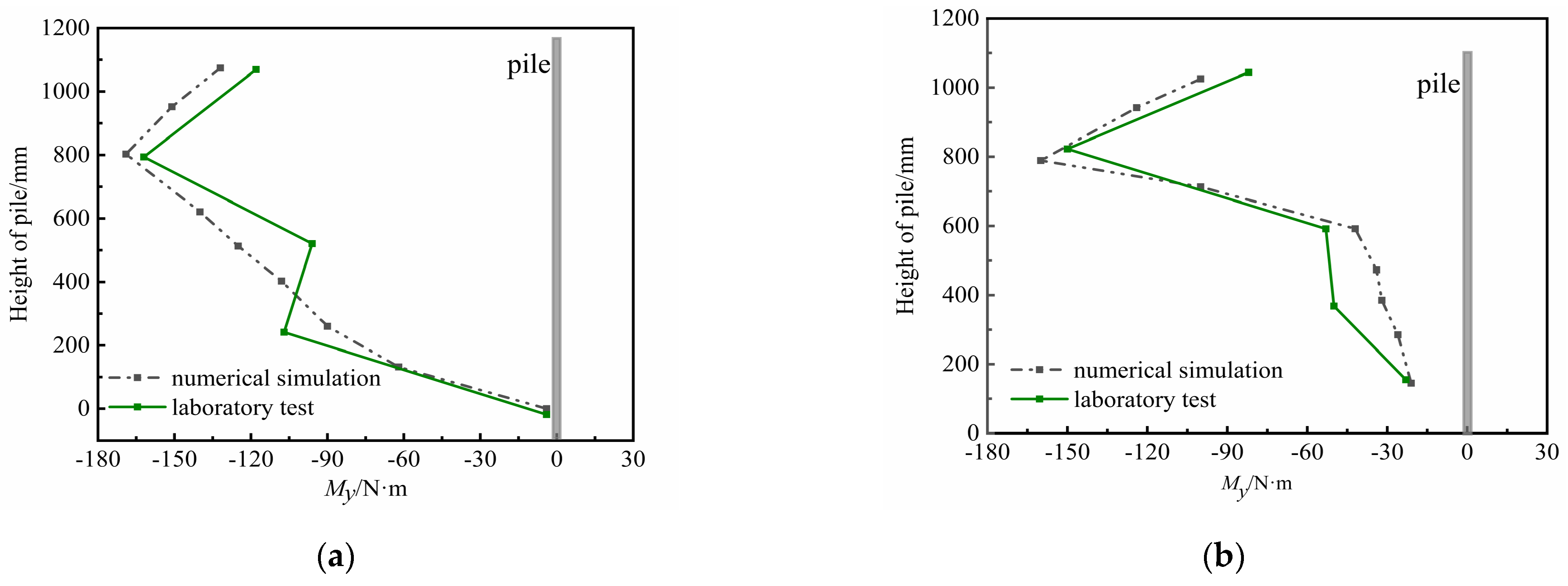
3.4.2. Bending Moment of Pile along the Downhill Direction (My)

According to the test results, the distribution regularity of My compared with the value of Mx was obviously different, as shown in Figure 11. The bending moment along the pile always was negative under different levels of load. However, the positions of extreme values of My and Mx were different, with a larger My in the upper part of the pile. This was due to the restrained effect from the crown beam on the pile top, which resulted in the extreme value of My appearing near the pile top. Thus, the mechanical behavior of the pile was improved. The load was continuously transmitted from the middle pile to the side piles through crown beam, with the extreme value of My appearing at the P11 top. Under the fifth level of load, the extreme values of My of P6, P8, P10, and P11 were −162.98 N·m, −150.86 N·m, −150.07 N·m, and −184.06 N·m, respectively. Thus, except for the P11, the extreme values of those three piles were similar, and their fluctuation ranges were within 10%. The maximum bending moment of P11 was larger than that of the other piles. It could make full use of the stable soil at the slope foot to resist the landslide thrust. The test showed that the slope was strengthened by the spatial arc crown beam composite supporting structure so as to distribute the relatively uniform load among different piles. Thus, the slope’s overall stability was improved. Furthermore, it can also be seen that the value of My at the pile end is small, which confirms again that the mechanical behavior of an anti-slide pile is similar to a vertical beam with a hinged pile end and fixed pile top.

4. Finite Element Numerical Calculation
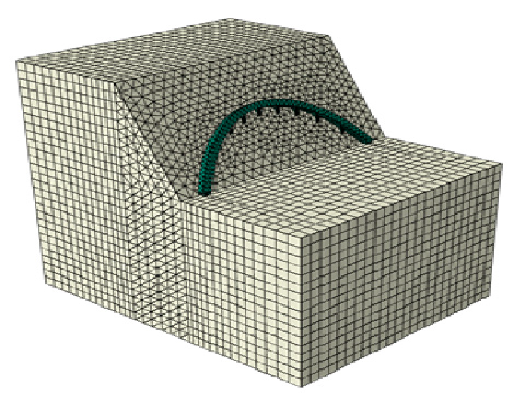
There were many limitations on the operation and analysis concerning the laboratory model test, and it was difficult for the engineer to specifically and comprehensively study the spatial arc crown beam composite supporting structure. However, ABAQUS serves as a powerful software for an in-depth finite element analysis on the bearing characteristics of slope reinforcement by the composite structure.

4.1. Model Building

A 3D model was established according to the actual size of the slope engineering. The slope angle was 60°; the actual dimension of the pile was 10 times that of the model piles in the laboratory model test; the sectional size of the crown beam was also expanded by 10 times. Due to the geometric axial symmetry of the composite structure, only P1–P6 were taken as research objectives for numerical simulation.
The constitutive model serves as the foundation for mechanical calculations and analysis, and the ABAQUS software can provide many constitutive models. Many scholars have shown that the Mohr–Coulomb model could work well for an analysis of the failure and deformation characteristics of soil [32,33]. The soil was used as an ideal elastic-plastic material with the Mohr–Coulomb yield criterion. The elasticity model was adopted for both the pile and the crown beam made of C30 concrete, and the relevant material parameters in the numerical simulation are listed in Table 3.
The contact property also determines the accuracy of results in the numerical simulation. Generally, contact pairs should be set at the pile–soil contact. The pile surface is set as the main surface; the soil surface is set as the slave surface, and the normal contact between the pile and the soil is set as hard contact. In this way, penetration between the pile and the soil can be avoided. The pile-soil interaction is adopted by the Coulomb friction model, whose feasibility and accuracy have been validated by many researchers [34,35]. The friction coefficient was set along the tangential direction, and the tangent value of the internal friction angle of the soil was taken as the friction coefficient [36,37]. The pile top and the crown beam were connected as a whole through the binding constraint, which ensured that the internal force of the pile top and crown beam were also equal at the node. Given both the geometric and mechanical characteristics of the 3D model, the mesh was divided more specifically in a relatively large number for the piles, the crown beam, and the soil mass near the piles and the crown beam. The mesh was divided more coarsely in a relatively small of the soil away from the piles and the crown beam, as shown in Figure 12.
In order to prevent rigid displacement in the model during numerical simulation, the fixed constraint was applied onto the bottom surface of the model, and simultaneously, the normal constraint was applied around all sides of the model. After the model was established, the stress and the displacement of the model were calculated first under the gravity load, and the initial ground stress balance was conducted for the model through imported ODB [38]. Only the initial ground stress balance condition was met. The vertical uniform load was applied on the slope top, which was divided into five levels, with 30 kPa of each level.

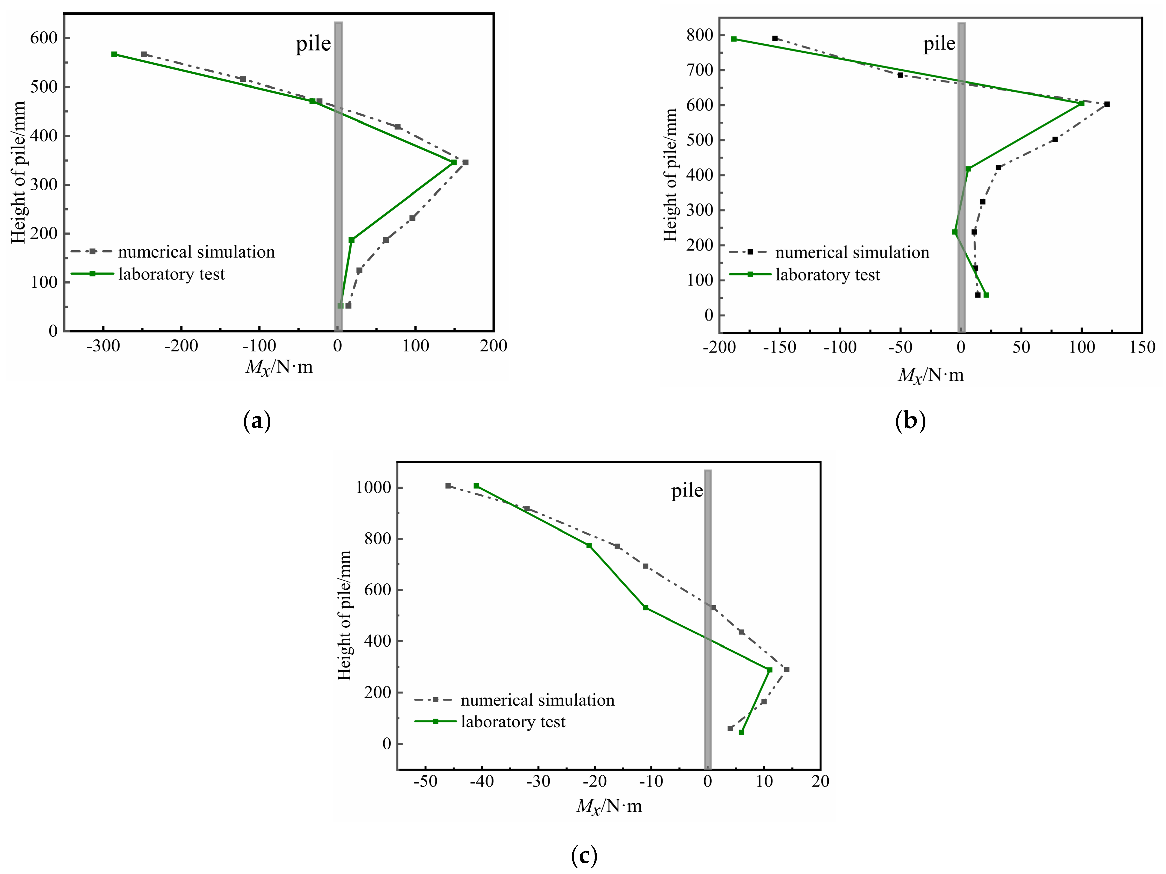
4.2. Numerical Simulation Verification

First, a numerical model was established according to the slope size in the lab-scale physical model test. Then, the results from the numerical simulation were compared with those from the laboratory model test. Due to the limitations in the laboratory model test, the bending moments of only five sections were tested along the pile. However, the bending moments of nine sections were extracted in the numerical simulation. The fifth load level was selected as the condition for verification during the analysis process, as shown in Figure 13 and Figure 14. Although there were numerical differences in the test point along the pile between the laboratory model test and the numerical simulation, their distribution characteristics along the pile of the bending moment were basically the same. Figure 13 indicates that the extreme values of Mx appear at the pile top, and the bending moments at the pile end are also close to zero. In Figure 14, the values of My were basically negative, and the extreme value of My appeared at a certain distance from the pile top. However, as for the piles located at the arch foot, their extreme values still appeared at the pile top. The values of Mx and My from the numerical simulation were consistent with the results from the laboratory model test; the distribution regularity of the pile was basically the same, and the difference in the extreme bending moments of each pile was within 8%.

4.3. Numerical Analysis Results

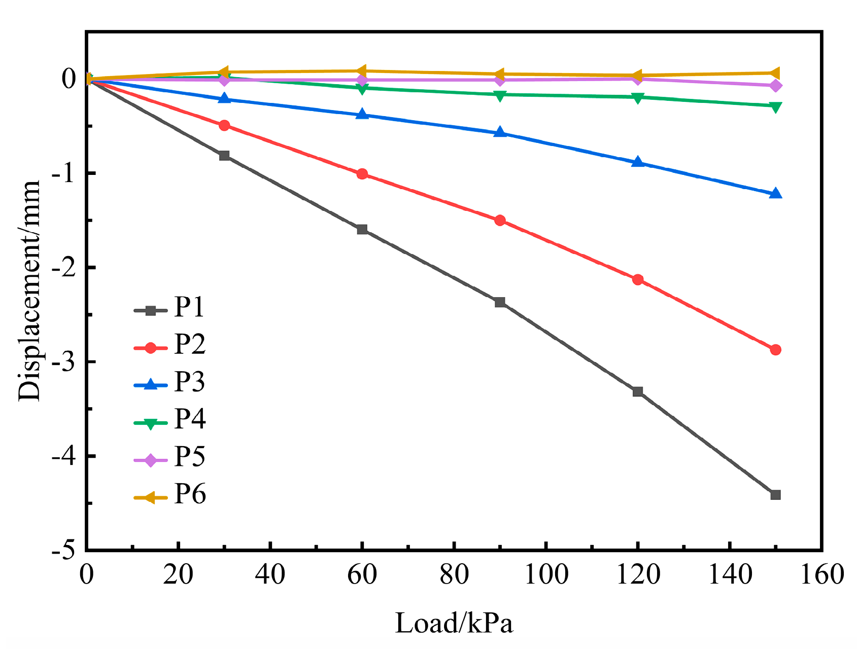
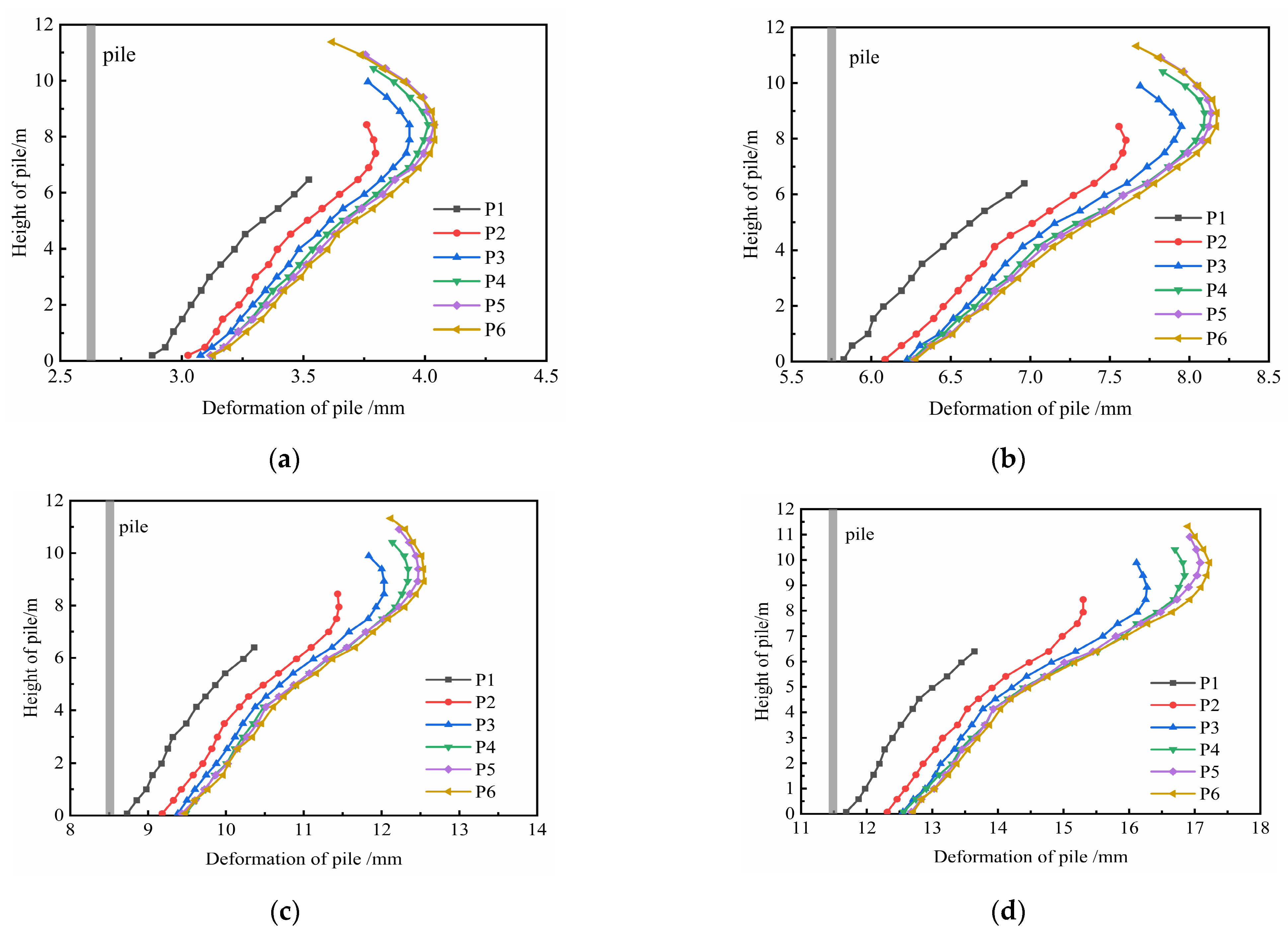
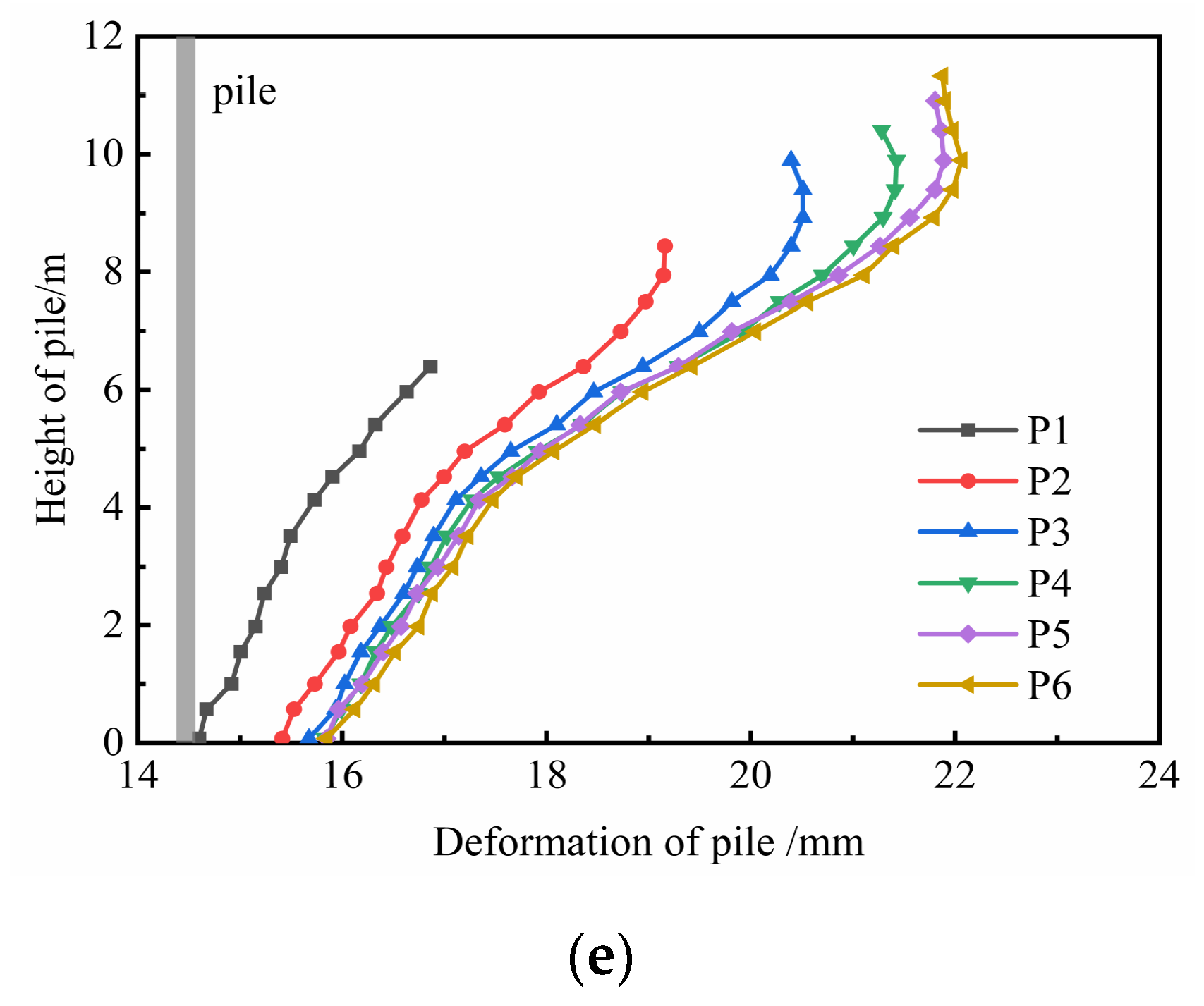
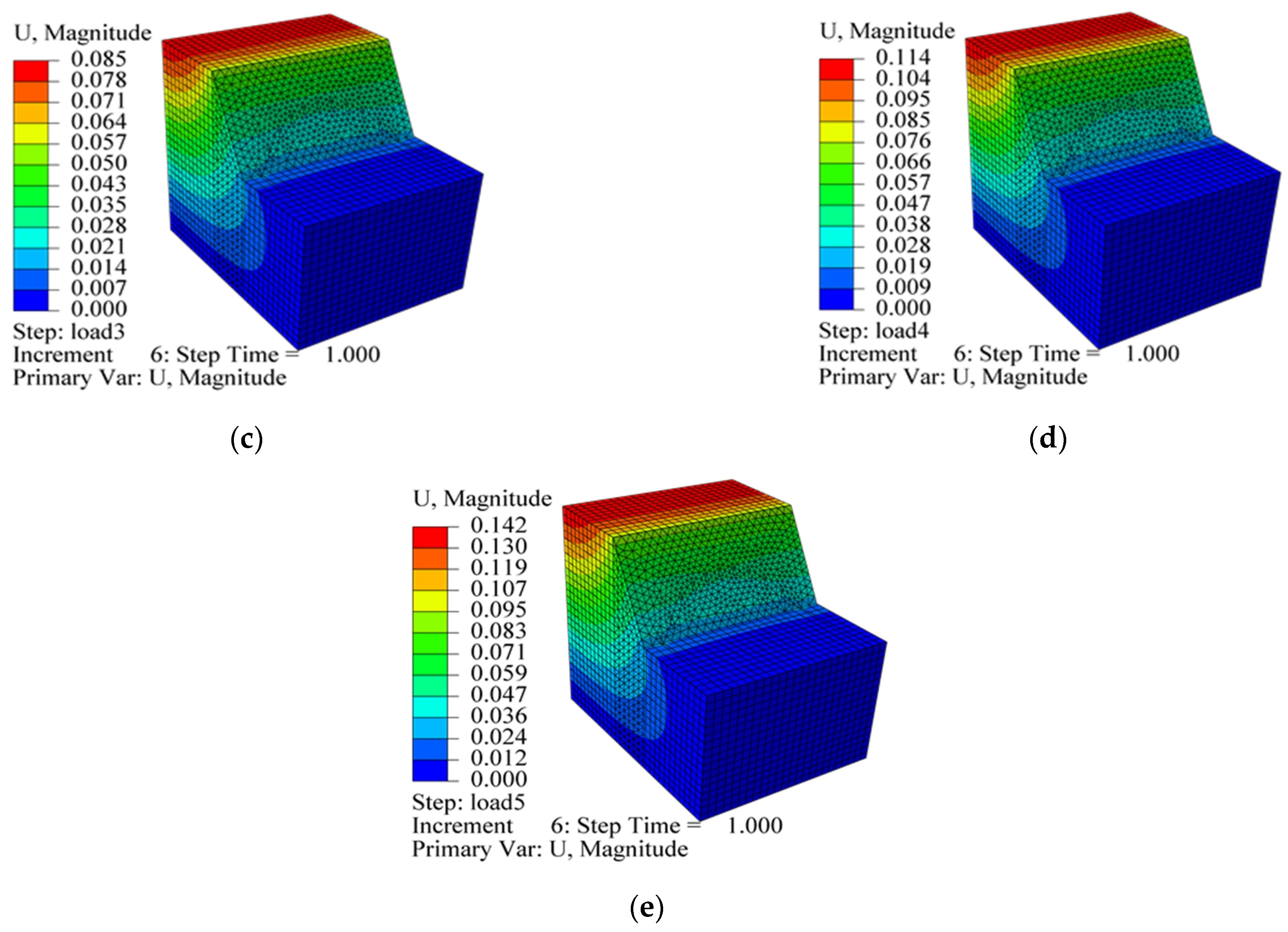
4.3.1. Pile Displacement

Under different levels of load at the slope top, the displacement of the pile top along the downhill direction (U1) and transverse slope direction (U2) is shown in Figure 15 and Figure 16, respectively. According to Figure 15, as the load increased, the U1 gradually increased from P1–P6 while the U2 gradually decreased in turn. When the load increased to the fifth level of load, the U1 of P1–P6 were 17.16 mm, 18.86 mm, 19.66 mm, 20.02 mm, 20.21 mm, and 20.23 mm, respectively. The U1 near the pile top was actually similar, and the variation amplitude was 2.9%. With the increase in the load, the distributed regularity of P3–P6 tended to overlap. Therefore, it was considered herein that the composited structure was defined by its overall movement behavior. However, the soil at the slope foot was relatively stable, and the U1 of P1 and P2 was small. In Figure 16, when the load at the slope top was 150 kPa, the U2 of P1–P4 was −4.06 mm, −2.60 mm, −1.05 mm, and −0.23 mm, respectively. The maximum value of U2 appeared at the top of P1, and the U2 of P5 and P6 were close to zero. On the whole, the maximum value of U2 among those six piles was less than 5 mm. This shows that the variations in U2 were small. As a result, the displacement of the pile top can be effectively controlled for slope reinforcement through the spatial arc crown beam composite supporting structure, which plays a role in deformation coordination.
The distributed regularity of pile displacement along the downhill direction is shown in Figure 17. The distribution curve of P1 was approximately straight while the pile was inclined. This is because the anti-slide pile at the slope foot was different from the anti-slide pile at other positions, the stable soil at the slope foot was fully utilized by P1 to resist the landslide thrust, and the soil below the P1 top was more stable. The maximum value of pile displacement gradually increased with the load. Due to the constraint effect by the crown beam on the pile top, the displacement first increased and then decreased from the top to the end. The maximum displacement ranged from 7 to 9 m away from the pile bottom. Under the fifth level of load, the values from P1 to P6 were 17.13 mm, 18.85 mm, 20.01 mm, 20.66 mm, 20.89 mm, and 20.96 mm, respectively, and the maximum values of pile displacement gradually increased. With the increase in the load, the displacement distribution from P4 to P6 was marked by coincidence, and the variation in displacement along the pile was no longer obvious. Compared with the displacement of P2–P6, the variation in P1 was the smallest. This also confirms that the soil at the slope foot plays a significant role in supporting the pile at the arch foot.

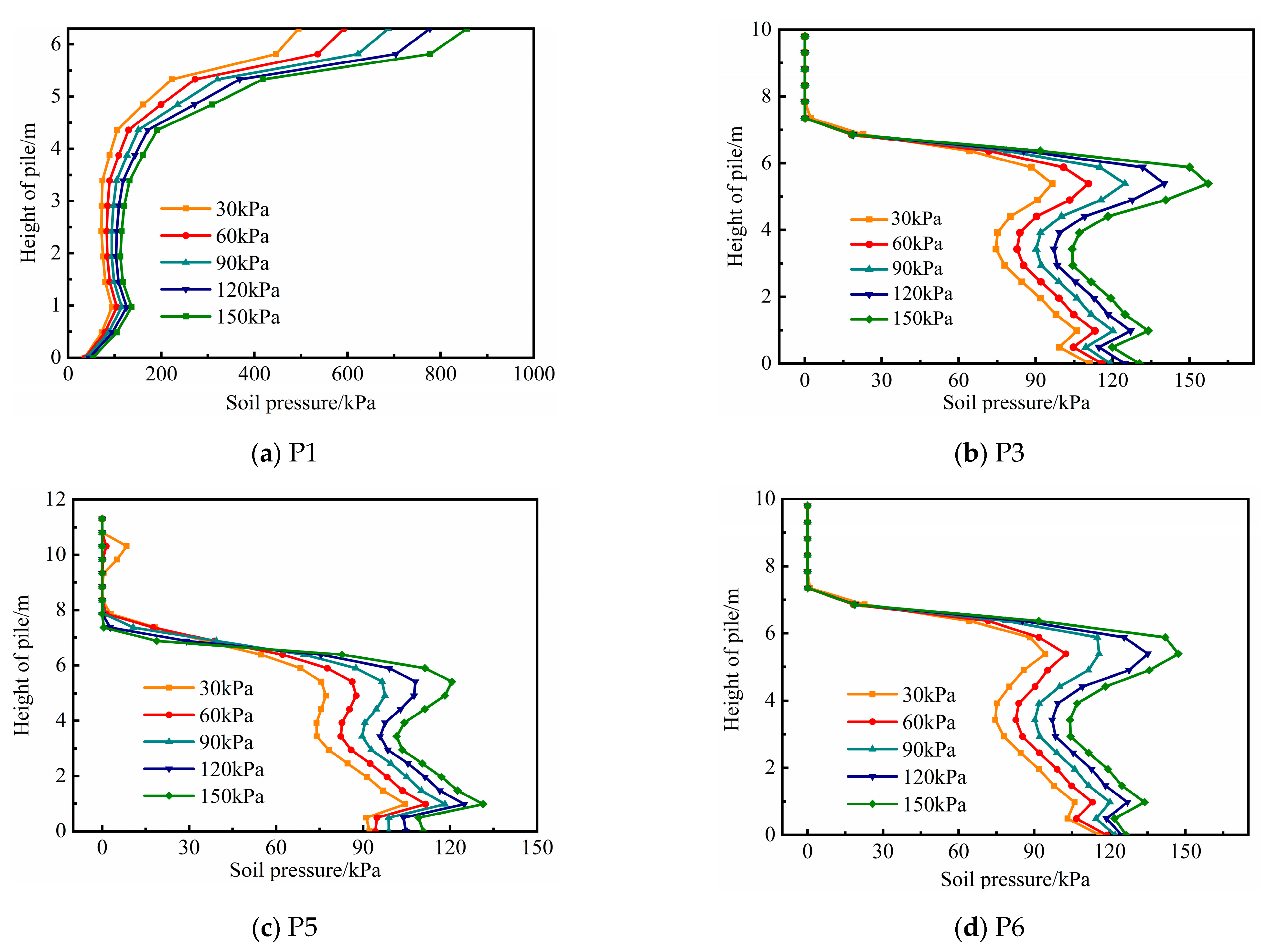
4.3.2. Soil Pressure

Figure 18 shows the displacement cloud of the slope soil, and the deformations were different at different positions on the top plane of slope. The soil displacement near the slope surface decreased significantly, whereas the displacement near the boundary of the slope top is relatively larger. The maximum displacement was 0.142 m under the fifth level of load. The soil displacement above the horizontal plane at the slope foot showed an obvious layered characteristic along the vertical direction. Due to the reinforcement effect of the composite structure and by virtue of the vertical plane at the slope foot where the side pile was located as the interface, the soil displacement variation below the horizontal plane at the slope foot was roughly divided into two parts. In the blue area on the right side, the soil displacement was close to zero, indicating that the soil deformation was basically unaffected. Thus, in a position close to the slope foot, the composite structure could effectively reduce the plastic zone of the slope. However, in the left region, the slope soil had an obvious deformation. Within the zone reinforced by the composite structure, the soil deformation decreased rapidly, and the soil deformation at the slope foot was close to zero. According to the variation regularity of displacement, the spatial arc crown beam composite supporting structure can reduce slope deformation and displacement, and thus landslide risks.
The soil pressure distribution regularity in the front of pile is shown in Figure 19. Before the plastic soil deformation, the soil pressure in the front of pile provides resistance for the anti-slide pile. The larger the soil pressure in the front of pile, the stronger the resistance effect would be. The soil pressure in the front of pile continuously increased with the load applied on the slope top. In particular, the extreme soil pressures in front of P1, P3, P5, and P6 under the fifth level of load were 856.29 kPa, 162.23 kPa, 133.63 kPa, and 147.03 kPa, respectively. It can be seen that the extreme soil pressure in front of P1 is the largest, and the maximum value appears on the pile top. The results show that soil stabilization at the slope foot can improve the supporting effect of side piles (P1 and P11).
Additionally, the distribution regularity of soil pressure in front of P3, P5, and P6 was different from that of P1 at the slope foot, which was zero near the upper part of these piles due to the thin soil in front of the pile on the slope surface and the loosened soil in a certain range near the pile top, leading to a separation phenomenon between the pile and the soil. However, the anti-slide piles were still in normal working condition; note that the ultimate displacement of the anti-slide pile was different from that of the pile foundation in the bridge and building foundation. Except for P1, the soil pressure in front of P3, P5, and P6 was larger near the middle and lower parts of those pile, which were less affected by landslide thrust. With the load increase on the slope top, the closer the soil was to the pile top, the faster the soil pressure increased. The overall soil pressure trend decreased, and the pile length influenced by the load was shorter than the designed length. The load transfer mechanism of the slope reinforcement by the spatial arc crown beam composite supporting structure is reasonable, and the stable soil near the slope foot can be used to avoid the destruction of soil in a large area and protect the natural and ecological environment.

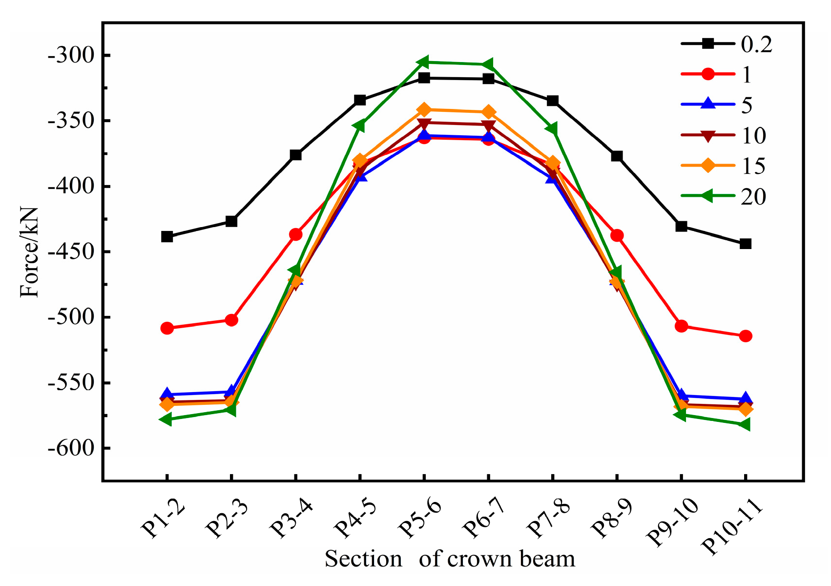
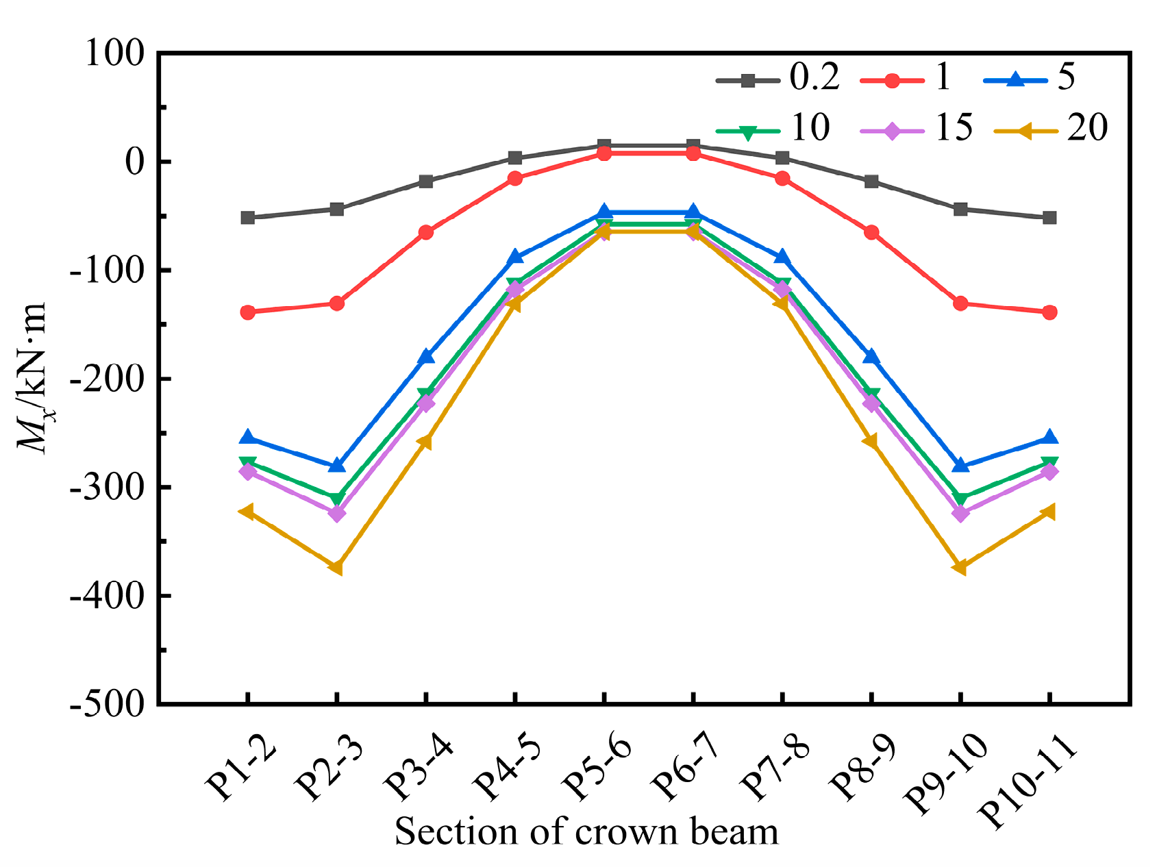
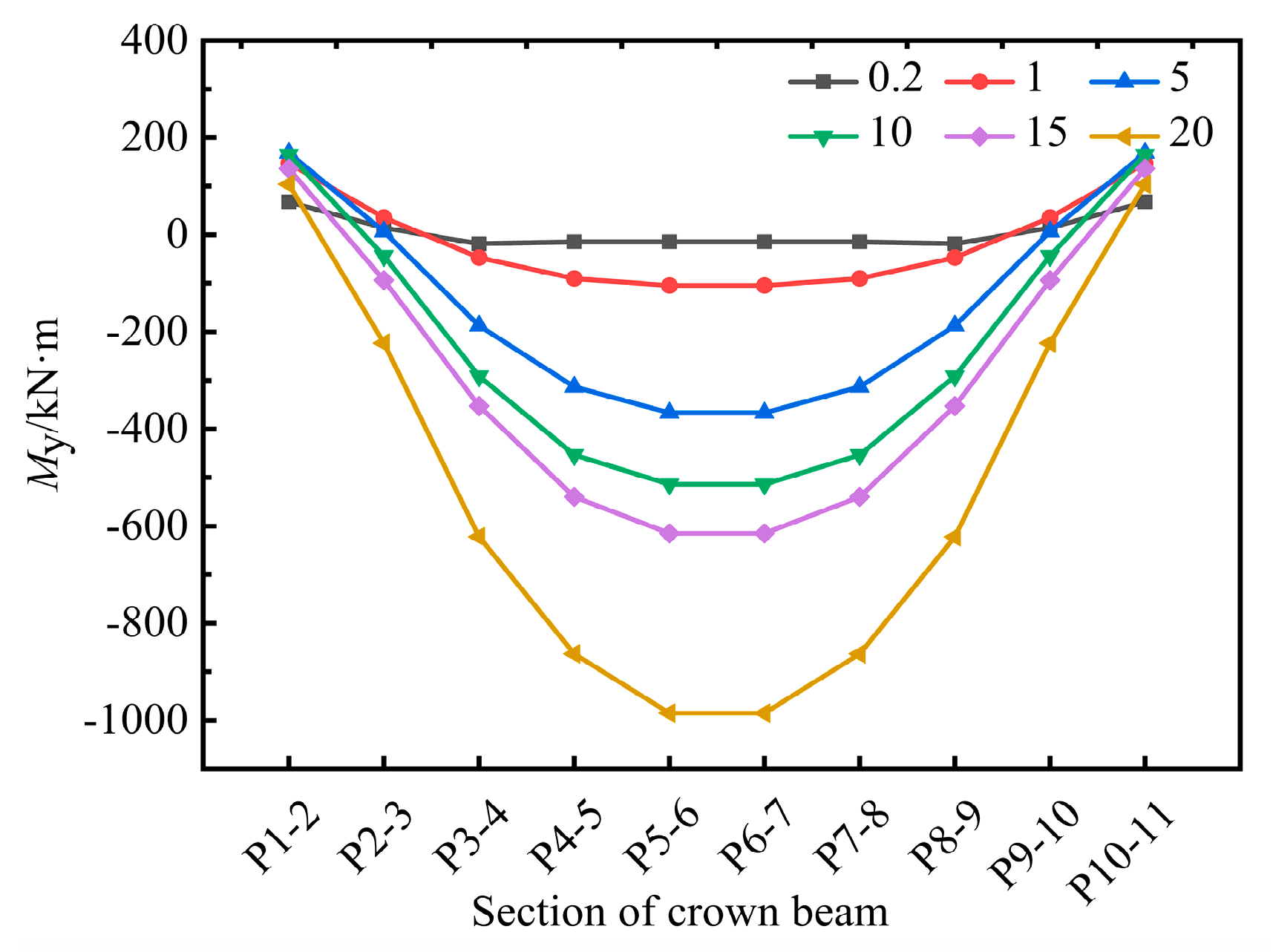
4.3.3. Crown Beam Stiffness

The crown beam works for load transfer, redistributes the load upon different anti-slide piles, and thus effectively controls the overall deformation of the composite structure. The crown beam stiffness was changed through an adjustment of its elastic modulus in order to further analyze the influence of stiffness upon the internal force of the top beam. Based on the reference value of the elastic modulus E = 30 GPa of the crown beam, six different elastic moduli were set, namely, 0.2, 1, 5, 10, 15, and 20 times the reference value, respectively. The axial force in the crown beam is shown in Figure 20. P1–2 represent a crown beam section between the P1 top and the P2 top. According to Figure 20, the crown beam stiffness had a great influence on axial force. The load was successively transmitted to side piles at the slope foot through the crown beam, and the axial force gradually increased from the arch vault to the arch foot. When the stiffness reached five times the reference value, the curve of the axial force tended to be stable. When the crown beam stiffness continued increased to 20 times the reference value, the axial force near the slope toe increased by about 30% compared with the stiffness of 0.2 times the reference value. However, the axial force at the arch vault decreased by about 16%, which was always the pressure.
The bending moments were generated in the arc crown beam along the downhill and the transverse slope direction and are shown in Figure 21 and Figure 22. When the crown beam stiffness was 0.2 and 1 times the reference value, respectively, Mx appeared of the P1–2 of the crown beam. As the crown beam stiffness continued to increase, the maximum value appeared at P2–3. However, the Mx of P5–6 was the smallest near the arch vault. The distribution regularity of My in the crown beam was opposite to Mx. The maximum My appeared at P5–6, and the minimum My appeared at P1–2. My of the crown beam was a positive value near the arch foot. As the crown beam stiffness increased, My of P5–6 increased continuously. As its stiffness was 20 times the reference value, My was −1013.13 kN·m. With the increase in stiffness, the constraining effect on the crown beam was gradually weakened. The results show that the increment in the crown beam stiffness can improve the mechanical behavior of piles only to a limited extent.

5. Conclusions

In this study, a new method was proposed for slope reinforcement by a spatial arc crown beam composite supporting structure. First, a laboratory model test was carried out to investigate the distribution regularity of the bending moment along the pile. Subsequently, a numerical model was developed using the finite element method for simulating the slope, and it was then verified by the measured data from physical model tests. Finally, a full-scale slope numerical model was developed to further analyze the distribution regularity of the pile displacement, soil pressure, as well as the influence from the crown beam stiffness upon the bending moment and the axial force of crown beam. Based on the lab-scale model test and the numerical results, the following conclusions were reached:
(1)
The spatial arc crown beam is simplified to a two-hinged arch. Compared with the straight crown beam, the maximum value of the bending moment in the arc crown beam is about one-third the quantity of the straight crown beam through theoretical calculation.
(2)
The spatial arc crown beam redistributes the load among different piles. The extreme values of the piles not at the slope foot vary within 10% along the downhill direction, and thus the mechanical characteristics of pile are more reasonable.
(3)
The bending moments are close to zero at the pile end, and the pile tops are connected through the arc crown beam. Thus, the anti-slide pile can be simplified as a vertical beam with one end fixed and one end hinged.
(4)
The axial force in the spatial arc crown beam is always presented as pressure. Therefore, the crown beam can make full use of the compression resistance of concrete and avoid the bending–shear failure in a straight crown beam.
(5)
The distribution characteristic of soil pressure in front of pile near the arch foot is different from that in other positions. The stable soil at the slope foot provides greater soil resistance for anti-piles than that in other positions. Although the soil pressure in front of the pile top is zero at the slope foot, the anti-slide piles are still within normal work conditions and thus can avoid the soil destruction in a large area.
(6)
As crown stiffness is above five times the reference value, the axial force of the crown beam tends to be stable. However, the stiffness increases continually to 20 times that the reference value. The maximum value of My is −1013.13 kN·m, and the constraining effect of the crown beam is gradually weakened.

Author Contributions

Conceptualization, Y.D.; Methodology, Y.D.; Software, Z.Y.; Validation, Z.Y.; Investigation, W.L. and K.Z.; Data curation, Z.Y. and C.P.; Writing—original draft, Z.Y.; Writing—review and editing, Y.D.; Project administration, Y.D.; Funding acquisition, Y.D. All authors have read and agreed to the published version of the manuscript.

Funding

The research described in the paper was supported by National Natural Science Foundation of China (Nos. 51878554 and 41672308) and Key Projects of Shaanxi Natural Science Basic Research Program (No. 2018JZ5012).

Institutional Review Board Statement

Not applicable.

Informed Consent Statement

Not applicable.

Data Availability Statement

All data generated or analysed during this study are included in this published article.

Conflicts of Interest

The authors declare no conflict of interest.

References

  1. Zhang, Y.L.; Feng, X.T.; Fan, J.H.; Fang, X.R. Study on the interaction between landside and passive piles. Chin. J. Rock Mech. Eng. 2002, 21, 839–842. [Google Scholar]
  2. Wang, C.C.; Li, J.T.; Liao, J.; Hao, R.Q.; Liu, B. Stability analysis of slope reinforced with piles and optimization. J. Cent. South Univ. (Sci. Technol.) 2015, 46, 231–237. [Google Scholar]
  3. Ito, T.; Matsui, T.; Hong, P.W. Design method for stabilizing piles against landslide-one row of piles. Soils Found. 1981, 21, 21–37. [Google Scholar] [CrossRef] [Green Version]
  4. Kourkoulis, R.; Gelagoti, F.; Anastasopoulos, I.; Gazetas, G. Slope stabilizing piles and pile-groups: Parametric study and design insights. J. Geotech. Geoenvironmental Eng. 2011, 137, 663–677. [Google Scholar] [CrossRef] [Green Version]
  5. Mohamed, A.; Hamed, A. Analysis of pile stabilized slopes based on soil-pile interaction. Comput. Geotech. 2015, 39, 85–97. [Google Scholar]
  6. Jiang, T.; Lei, J.H.; Wang, R.Z.; Zhang, J.R. Comparative model test study on reinforcement effect of anti-slide pile with different arrangements. J. Basic Sci. Eng. 2019, 27, 404–417. [Google Scholar]
  7. Qiu, Z.Y.; Han, T.C.; Dou, H.Q.; Li, Z.N. Analysis of spacing between anti-slide piles considering soil arch on lateral sides and back. J. Zhejiang Univ. (Eng. Sci.) 2016, 50, 559–565. [Google Scholar]
  8. Xiao, S.G. A simplified approach for stability analysis of slopes reinforced with one row of embedded stabilizing piles. Bull. Eng. Geol. Environ. 2017, 76, 1371–1382. [Google Scholar] [CrossRef]
  9. Xiao, S.G.; Zeng, J.X.; Yan, Y.P. A rational layout of double-row stabilizing piles for large-scale landslide control. Bull. Eng. Geol. Environ. 2017, 76, 309–321. [Google Scholar] [CrossRef]
  10. Lei, H.Y.; Liu, X.; Song, Y.J.; Xu, Y.G. Stability analysis of slope reinforced by double-row stabilizing piles with different locations. Nat. Hazards 2021, 106, 19–42. [Google Scholar] [CrossRef]
  11. Li, C.D.; Chen, W.Q.; Song, Y.J.; Gong, W.P.; Zhao, Q.H. Optimal location of piles in stabilizing slopes based on a simplified double-row piles model. KSCE J. Civ. Eng. 2020, 24, 377–389. [Google Scholar] [CrossRef]
  12. Shen, Y.J.; Sun, Y.H.; Shang, Y.Q.; Huang, L.; Yan, K.W. Distribution of landslide thrust on cantilever double-row anti-sliding piles. Chin. J. Rock Mech. Eng. 2012, 31, 2668–2672. [Google Scholar]
  13. Xie, Q.; Cao, Z.L.; Shi, X.K.; Fu, X.; Ban, Y.X.; Wu, Z.H. Model test of interaction between load-caused landslide and double-row anti-slide piles by transparent soil material. Arab. J. Sci. Eng. 2021, 46, 4841–4856. [Google Scholar] [CrossRef]
  14. Lai, J.; Zheng, Y.R.; Liu, Y.; Li, A.H.; Liu, H.W. Shaking table test studies and numerical analysis of double-row anti-slide piles under earthquake. J. Cent. South Univ. (Sci. Technol.) 2015, 46, 4307–4315. [Google Scholar]
  15. Ai, H.; Wu, H.G.; Feng, W.Q.; Chen, X.Y. Research on seismic capacity correlative experiment of top beam binding anti-slide pile and common anti-slide pile. J. Disaster Prev. Mitig. Eng. 2017, 37, 194–200. [Google Scholar]
  16. Zhou, Y.H. Analysis of distribution characteristics of stress and displacement of portal double-row pile. J. Railw. Eng. Soc. 2009, 26, 30–33. [Google Scholar]
  17. Qian, T.H.; Xu, H.; Xia, W.C.; Chen, F. Force analysis of framed anti-slide piles. China J. Highw. Transp. 2012, 25, 56–59. [Google Scholar]
  18. Xiong, S.; Li, C.D.; Yao, W.M.; Yan, S.Y.; Wang, G.H.; Zhang, Y.Q. Physical model tests and numerical modeling of stabilizing mechanism of portal double-row piles in landslides with inter bedded weak and hard bedrock. Bull. Eng. Geol. Environ. 2022, 81, 30–33. [Google Scholar] [CrossRef]
  19. Lirer, S. Landslide stabilizing piles: Experimental evidences and numerical interpretation. Eng. Geol. 2012, 149–150, 70–77. [Google Scholar] [CrossRef]
  20. Dai, Z.H.; Qiu, Z.H.; Li, H.Y.; Lu, C.J.; Yang, J.H. Laboratory model test of fully buried portal frame-shaped slope-stabilizing piles. Geotech. Test. J. 2022, 45, 390–410. [Google Scholar] [CrossRef]
  21. Qiao, S.F.; Xu, P.; Teng, J.D.; Sun, X. Numerical study of optimal parameters on the high filling embankment landslide reinforced by the portal anti-Slide pile. KSCE J. Civ. Eng. 2020, 24, 1460–1475. [Google Scholar] [CrossRef]
  22. LI, B.; Wang, Z.Z. Numerical study on the response of ground movements to construction activities of a metro station using the pile-beam-arch method. Tunn. Undergr. Space Technol. 2019, 88, 209–220. [Google Scholar] [CrossRef]
  23. Guo, X.Y.; Wang, Z.Z.; Geng, P.; Chen, C.G.; Zhang, J. Ground surface settlement response to subway station construction activities using pile-beam-arch method. Tunn. Undergr. Space Technol. 2021, 108, 103729. [Google Scholar] [CrossRef]
  24. Luo, L.J.; Zhao, F.S.; Wang, A.Z. Deformation character of landslide and its supporting structure in area of metamorphic rocks. J. Earth Sci. Environ. 2008, 30, 177–182. [Google Scholar]
  25. Zhang, Z.W.; Deng, R.G. Theoretical study of spatial anti-slide structure of arc interval row piles with coupling beam on pile top. Rock Soil Mech. 2013, 34, 3403–3409. [Google Scholar]
  26. Zhang, Y.; Xue, B.Y.; Song, X.H.; Chen, H.; Chen, W.Y. Study on reinforcing effect of arc row anti-slide piles with different forms in slope. Coal Sci. Technol. 2020, 48, 75–82. [Google Scholar]
  27. Chen, H.; Chen, W.Y.; Song, X.H.; Lin, G.J.; Zheng, J.G.; Wu, C. Dynamic response and stability of arc anti-slide piles in slope reinforcement under earthquake. Saf. Environ. Eng. 2020, 27, 79–86, 101. [Google Scholar]
  28. He, J.M.; Bai, S.W. Study of cooperative action between row of piles and ring beam for deep foundation pit supporting structure. Rock Soil Mech. 1997, 18, 41–46. [Google Scholar]
  29. Gao, Y.L. Simplified analysis of retaining piles considering spatial effect of ring beam. Rock Soil Mech. 1999, 20, 76–80. [Google Scholar]
  30. The Second Survey and Design Institute of the Ministry of Railways. Design and Calculation of Anti Slide Pile; China Railway Publishing House: Beijing, China, 1983. [Google Scholar]
  31. Zhang, Z.W.; Deng, R.G.; Wang, Z.Y.; Zhong, Z.B. Study on the effect of different constraint condition at pile bottom on internal force distribution of arc row piles with arc coupling beam. J. Chongqing Jiaotong Univ. (Nat. Sci.) 2015, 34, 81–86. [Google Scholar]
  32. Miao, L.F.; Goh, A.T.C.; Wong, K.S.; Teh, C.I. Three-dimensional finite element analyses of passive pile behaviour. Int. J. Numer. Anal. Methods Geomech. 2006, 30, 599–613. [Google Scholar] [CrossRef]
  33. Georgiadis, K. Variation of limiting lateral soil pressure with depth for pile rows in clay. Comput. Geotech. 2014, 62, 164–174. [Google Scholar] [CrossRef]
  34. Rose, A.V.; Taylor, R.N.; EI Naggar, M.H. Numerical modelling of perimeter pile groups in clay. Can. Geotech. J. 2013, 50, 250–258. [Google Scholar] [CrossRef]
  35. Haiderali, A.E.; Madabhushi, G. Evaluation of curve fitting techniques in deriving p-y curves for laterally loaded piles. Geotech. Geol. Eng. 2016, 34, 1453–1473. [Google Scholar] [CrossRef] [Green Version]
  36. Rahmani, A.; Taiebat, M.; Liam Finn, W.D.; Ventura, E.C. Evaluation of p-y springs for nonlinear static and seismic soil-pile interaction analysis under lateral loading. Soil Dyn. Earthq. Eng. 2018, 115, 438–447. [Google Scholar] [CrossRef]
  37. Deng, Y.S.; Peng, C.P.; Liu, J.C.; Li, L.T.; Fu, Y.B. Optimization and mechanical characteristics of spatial arc antislide pile. Adv. Civ. Eng. 2021, 2021, 6508675. [Google Scholar] [CrossRef]
  38. Jesmani, M.; Kasrania, A.; Kamalzare, M.; Mehdipour, I. Undrained vertical bearing capacity of pile located near soft clay slope. J. Eng. Res. 2015, 3, 21–38. [Google Scholar] [CrossRef]
Figure 1. The basic system of two-hinged arch.
Applsci 13 00293 g001
Figure 2. Radial horizontal force acting on the left half span.
Applsci 13 00293 g002
Figure 3. yp ≥ yji that αji-p ≥ 0.
Applsci 13 00293 g003
Figure 4. yp < yji that αji-p < 0.
Applsci 13 00293 g004
Figure 5. Calculation model of anti-slide pile.
Applsci 13 00293 g005
Figure 6. Physical dimensions of slope model: (a) physical slope model; (b) dimensions of slope model (unit: mm).
Applsci 13 00293 g006
Figure 7. Spatial arc crown beam composite supporting structure (unit: mm).
Applsci 13 00293 g007
Figure 8. Layout of strain gauges (unit: mm).
Applsci 13 00293 g008
Figure 9. Bending analysis of pile.
Applsci 13 00293 g009
Figure 10. Bending moment of pile along the transverse slope direction: (a) P1; (b) P2; (c) P4.
Applsci 13 00293 g010
Figure 11. Bending moment of pile along the downhill direction: (a) P6; (b) P8; (c) P10; (d) P11.
Applsci 13 00293 g011
Figure 12. Mesh subdivision.
Applsci 13 00293 g012
Figure 13. Comparison of Mx between laboratory model test and numerical simulation: (a) P1; (b) P2; (c) P4.
Applsci 13 00293 g013
Figure 14. Comparison of My between laboratory test and numerical simulation: (a) P6; (b) P8; (c) P10; (d) P11.
Applsci 13 00293 g014aApplsci 13 00293 g014b
Figure 15. Pile top displacement along the downhill direction.
Applsci 13 00293 g015
Figure 16. Pile top displacement along the cross-slope direction.
Applsci 13 00293 g016
Figure 17. Distribution regularity of displacement: (a) 30 kPa; (b) 60 kPa; (c) 90 kPa; (d) 120 kPa; (e) 150 kPa.
Applsci 13 00293 g017aApplsci 13 00293 g017b
Figure 18. Displacement cloud of slope soil: (a) 30 kPa; (b) 60 kPa; (c) 90 kPa; (d) 120 kPa;(e) 150 kPa.
Applsci 13 00293 g018aApplsci 13 00293 g018b
Figure 19. Soil pressure in front of pile: (a) P1; (b) P3; (c) P5; (d) P6.
Applsci 13 00293 g019
Figure 20. Axial force of crown beam.
Applsci 13 00293 g020
Figure 21. Mx of crown beam.
Applsci 13 00293 g021
Figure 22. My of crown beam.
Applsci 13 00293 g022
Table 1. Scaling relationships used in the physical model test.
ParametersSimilitude RelationsSimilitude Ratios
Dimension, L (m)CL10
Acceleration of gravity, g (g/s2)Cg = 11
Cohesion, c (kPa)Cc = 11
Internal friction angle, φ (°)Cφ = 11
Density, ρ (g/cm3)Cρ = 11
Elasticity modulus, E (MPa)CE = CL1
Strain, εCε = CL1
Table 2. Length of model piles.
Pile NumberP1P2P3P4P5P6P7P8P9P10P11
Pile length/mm63084098010801130115011301080980840630
Table 3. Material parameters.
MaterialsUnit Weight (kN/m3)Cohesion (kPa)Internal Friction Angle (°)Poisson’s Ratio Elasticity Modulus E (MPa)Unit TypeConstitutive Model
Soil20.842.530.050.3216.38SolidElastic-plastic
model
Crown Beam240.23 × 104soildElastic model
Pile240.23 × 104SolidElastic model
Disclaimer/Publisher’s Note: The statements, opinions and data contained in all publications are solely those of the individual author(s) and contributor(s) and not of MDPI and/or the editor(s). MDPI and/or the editor(s) disclaim responsibility for any injury to people or property resulting from any ideas, methods, instructions or products referred to in the content.

