
Approach-Based Analysis on Wireless Power Transmission for Bio-Implantable Devices

Abstract
:1. Introduction
2. Wireless Power Transfer
3. Analysis of Various WPT Approaches
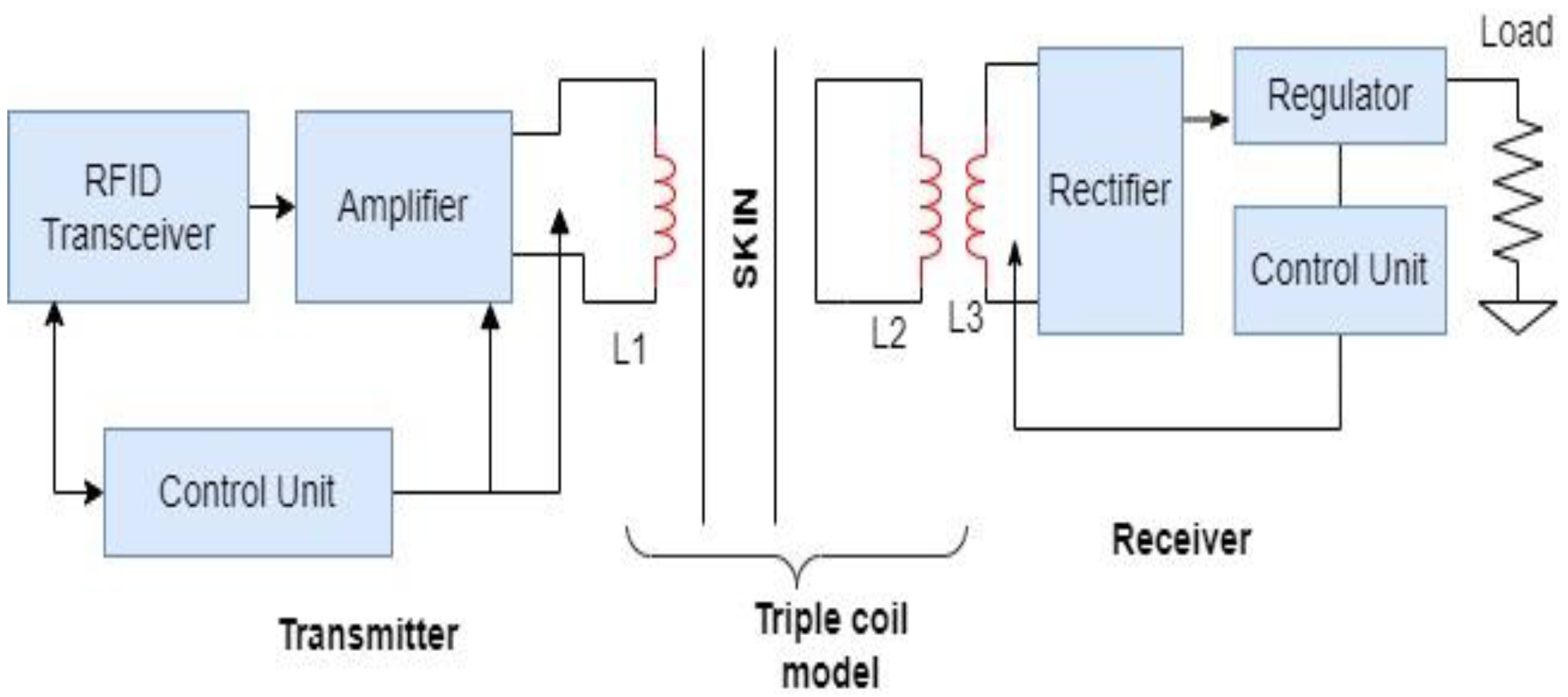
3.1. WPT Systems Based on Different Transmitting and Receiving Coils Technique
3.2. WPT Based on Role of Impedance Matching Approach and Hybrid Technique
3.3. WPT Systems Based on Power Control and Regulation Improvement
3.4. WPT Systems Based on Antenna Modifications
4. Conclusions
Funding
Institutional Review Board Statement
Informed Consent Statement
Acknowledgments
Conflicts of Interest
References
- Poisel, R. Antenna Systems and Electronic Warfare Applications; Artech House: Norwood, MA, USA, 2011; ISBN 1608074846. [Google Scholar]
- Brown, W.C. Beamed Microwave Power Transmission and its application to space. IEEE Trans Microw. Theory Tech. 1992, 40, 1239–1250. [Google Scholar] [CrossRef]
- Kiani, M.; Ghovanloo, M. An RFID-Based Closed-Loop Wireless Power Transmission System for Biomedical Applications. IEEE TCAS-II 2010, 57, 260–264. [Google Scholar] [CrossRef] [PubMed] [Green Version]
- Flack, F.C.; James, E.D.; Schlapp, D.M. Mutual inductance of air-cored coils: Effect on design of radio-frequency coupled implants. Med. Biol. Eng. 1971, 9, 79–85. [Google Scholar] [CrossRef] [PubMed]
- Schuder, J.C.; Gold, J.H.; Stephenson, H.E. An inductively coupled RF system for the transmission of 1 kW of power through the skin. IEEE Trans. Biomed. Eng. 1971, BME-18, 265–273. [Google Scholar] [CrossRef] [PubMed]
- Ko, W.H.; Liang, S.P.; Fung, C.D.F. Design of radiofrequency powered coils for implant instruments. Med. Biol. Eng. Comput. 1977, 15, 634–640. [Google Scholar] [CrossRef]
- Donaldson, N.d.N.; Perkins, T.A. Analysis of resonant coupled coils in the design of radio frequency transcutaneous links. Med. Biol. Eng. Comput. 1983, 21, 612–627. [Google Scholar] [CrossRef]
- von Arx, J.A.; Najafi, K. A wireless single-chip telemetry powered neural stimulation system. In Proceedings of the 1999 IEEE International Solid-State Circuits Conference, San Francisco, CA, USA, 17 February 1999; pp. 214–215. [Google Scholar]
- Heetderks, W.J. RF powering of millimeter- and submillimeter-sized neural prosthetic implants. IEEE Trans. Biomed. Eng. 1988, 35, 323–327. [Google Scholar] [CrossRef] [Green Version]
- Zierhofer, C.M.; Hochmair, E.S. High-efficiency coupling-insensitive transcutaneous power and data transmission via an inductive link. IEEE Trans. Biomed. Eng. 1990, 37, 716–722. [Google Scholar] [CrossRef] [Green Version]
- van Schuylenbergh, K.; Puers, R. Self-tuning inductive powering for implantable telemetric monitoring systems. In Proceedings of the 8th international conference on Solid-State Sensors and Actuators and Eurosensors IX, Stockholm, Sweden, 25–29 June 1995; Volume 1, pp. 1–7. [Google Scholar]
- Akin, T.; Najafi, K.; Bradley, R.M. A wireless implantable multichannel digital neural recording system for a micromachined sieve electrode. IEEE J. Solid-State Circuits 1998, 33, 109–118. [Google Scholar] [CrossRef] [Green Version]
- Dai, J.; Ludois, D.C. A survey of wireless power transfer and a critical comparison of inductive and capacitive coupling for small gap applications. IEEE Trans. Power Electron. 2015, 30, 6017–6029. [Google Scholar] [CrossRef]
- Covic, G.A.; Boys, J.T. Inductive power transfer. Proc. IEEE 2013, 101, 1276–1289. [Google Scholar] [CrossRef]
- Tang, S.C.; Hui, S.Y.R.; Chung, H.S.H. Coreless planar printed circuit-board (PCB) transformers-a fundamental concept for signal and energy transfer. IEEE Trans Power Electron. 2000, 15, 931–941. [Google Scholar] [CrossRef] [Green Version]
- Kurs, A.; Karalis, A.; Moffatt, R.; Joannopoulos, J.D.; Fischer, P.; Soljacic, M. Wireless Energy transfer via strongly coupled Magnetic Resonance. Science 2007, 317, 83–86. [Google Scholar] [CrossRef] [Green Version]
- Ramrakhiyani, A.K.; Mirabbasi, S.; Chiao, M. Design and Optimization of Resonance-Based Efficient Wireless Power Delivery Systems for Biomedical Implants. IEEE Trans Biomed. Circuits Syst. 2011, 5, 48–63. [Google Scholar] [CrossRef]
- Ramrakhiyani, A.K.; Lazzi, G. On the Design of Efficient MultiCoil Telemetry System for Biomedical Implants. IEEE Trans Biomed. Circuits Syst. 2013, 7, 11–23. [Google Scholar] [CrossRef]
- Zhao, B.; Kuo, N.-C.; Niknejad, A.M. A Gain Boosting Array Technique for Weakly-Coupled Wireless Power Transfer. IEEE Trans. Power Electron. 2017, 32, 7130–7139. [Google Scholar] [CrossRef]
- Liu, C.; Jiang, C.; Song, J.; Chau, K.T. An Effective Sandwiched Wireless Power Transfer System for Charging Implantable Cardiac Pacemaker. IEEE Trans. Ind. Electron. 2018, 66, 4108–4117. [Google Scholar] [CrossRef]
- Liu, Y.; Li, Y.; Zhang, J.; Dong, S.; Cui, C.; Zhu, C. Design a Wireless Power Transfer System with Variable Gap Applied to Left Ventricular Assist Devices. In Proceedings of the 2018 IEEE PELS Workshop on Emerging Technologies: Wireless Power Transfer, Wow 2018, Montréal, QC, Canada, 29 August 2018. [Google Scholar] [CrossRef]
- Chen, P.; Yang, H.; Luo, R.; Zhao, B. A Tissue-Channel Transcutaneous Power Transfer Technique for Implantable Devices. IEEE Trans. Power Electron. 2018, 33, 9753–9761. [Google Scholar] [CrossRef]
- Chen, J.; Xu, J. A new coil structure for implantable wireless charging system. Biomed. Signal Process. Control. 2021, 68, 102693. [Google Scholar] [CrossRef]
- Stoecklin, S.; Yousaf, A.; Gidion, G.; Reindl, L. Efficient Wireless Power Transfer With Capacitively Segmented RF Coils. IEEE Access 2020, 8, 24397–24415. [Google Scholar] [CrossRef]
- Zhang, X.; Lu, X.; Zhang, X.; Wang, L. A novel three-coil wireless power transfer system and its optimization for implantable biomedical applications. Neural Comput. Appl. 2020, 32, 7069–7078. [Google Scholar] [CrossRef]
- Campi, T.; Cruciani, S.; De Santis, V.; Maradei, F.; Feliziani, M. Near Field Wireless Powering of Deep Medical Implants. Energies 2019, 12, 2720. [Google Scholar] [CrossRef] [Green Version]
- Xu, D.; Zhang, Q.; Li, X. Implantable Magnetic Resonance Wireless Power Transfer System Based on 3D Flexible Coils. Sustainability 2020, 12, 4149. [Google Scholar] [CrossRef]
- Campi, T.; Cruciani, S.; Maradei, F.; Feliziani, M. Coil Design of a Wireless Power-Transfer Receiver Integrated into a Left Ventricular Assist Device. Electronics 2021, 10, 874. [Google Scholar] [CrossRef]
- Masuda, S.; Hirose, T.; Akihara, Y.; Kuroki, N.; Numa, M.; Hashimoto, M. Impedance Matching in Magnetic-Coupling-Resonance Wireless Power Transfer for Small Implantable Devices. In Proceedings of the IEEE Wireless Power Transfer Conference, Taipei, China, 10–12 May 2017; pp. 1–3. [Google Scholar]
- Bisschop, M.; Serdijn, W.A. Resistive Matching using an AC Boost Converter for Efficient Ultrasonic Wireless Power Transfer. In Proceedings of the IEEE Wireless Power Transfer Conference (WPTC), London, UK, 17–23 June 2019. [Google Scholar]
- Pérez-Nicoli, P.; Biancheri-Astier, M.; Diet, A.; Le Bihan, Y.; Pichon, L.; Silveira, F. Influence of the Titanium Case used in Implantable Medical Devices on the Wireless Power Link. In Proceedings of the 2018 IEEE Wireless Power Transfer Conference (WPTC), Montreal, QC, Canada, 3–7 June 2018. [Google Scholar]
- Koruprolu, A.; Nag, S.; Erfani, R.; Mohseni, P. Capacitive Wireless Power and Data Transfer for Implantable Medical Devices. In Proceedings of the 2018 IEEE Biomedical Circuits and Systems Conference (BioCAS), Cleveland, OH, USA, 17–19 October 2018. [Google Scholar]
- Li, X.; Tsui, C.Y.; Ki, W.H. A 13.56 MHz Wireless Power Transfer System with Reconfigurable Resonant Regulating Rectifier and Wireless Power Control for Implantable Medical Devices. In Proceedings of the IEEE 2014 Symposium on VLSI Circuits Digest of Technical Papers, Honolulu, HI, USA, 10–13 June 2014. [Google Scholar]
- Zhao, Y.; Tang, X.; Wang, Z.; Ng, W.T. An Inductive Power Transfer System with Adjustable Compensation Network For Implantable Medical Devices. In Proceedings of the 2019 IEEE Asia Pacific Conference on Circuits and Systems (APCCAS), Bangkok, Thailand, 11–14 November 2019. [Google Scholar]
- Zhu, G.; Mai, S.; Zhang, C.; Wang, Z. Distance and load insensitive Inductive Powering for implantable medical devices through wireless communication. In Proceedings of the 2017 IEEE Wireless Power Transfer Conference (WPTC), Taipei, Taiwan, 10–12 May 2017. [Google Scholar]
- Kim, J.; Marin, G.; Seo, J.M.; Neviani, A. A 13.56 MHz reconfigurable step-up switched capacitor converter for wireless power transfer system in implantable medical devices. Analog. Integr. Circuits Signal Process. 2022, 110, 517–525. [Google Scholar] [CrossRef]
- Shin, S.U.; Choi, M.; Jung, S.; Lee, H.M.; Cho, G.H. A Time-Interleaved Resonant Voltage Mode Wireless Power Receiver with Delay-Based Tracking Loops for Implantable Medical Devices. IEEE J. Solid-State Circuits 2019, 55, 1374–1385. [Google Scholar] [CrossRef]
- Akram, M.A.; Yang, K.W.; Ha, S. Duty-Cycled Wireless Power Transmission for Millimeter-Sized Biomedical Implants. Electronics 2020, 9, 2130. [Google Scholar] [CrossRef]
- Bakogianni, S.; Koulouridis, S. A Dual-Band Implantable Rectenna for Wireless Data and Power Support at Sub-GHz Region. IEEE Trans. Antennas Propag. 2019, 67, 6800–6810. [Google Scholar] [CrossRef]
- Das, R.; Yoo, H. A Multiband Antenna Associating Wireless Monitoring and Non-leaky Wireless Power Transfer System for Biomedical Implants. IEEE Trans. Microw. Theory Tech. 2017, 65, 2485–2495. [Google Scholar] [CrossRef]
- Lee, B.; Kiani, M.; Ghovanloo, M. A Triple-Loop Inductive Power Transmission System for Biomedical Applications. IEEE Trans. Biomed. Circuits Syst. 2015, 10, 138–148. [Google Scholar] [CrossRef]
- Shaw, T.; Mandal, B.; Mitra, D.; Augustine, R. Wireless Power Transfer System Design in Reactive Near-Field for Implantable Devices. In Proceedings of the 2020 14th European Conference on Antennas and Propagation (EuCAP), Copenhagen, Denmark, 15–20 March 2020. [Google Scholar]
- Zhang, H.; Gao, S.P.; Ngo, T.; Wu, W.; Guo, Y.X. Wireless Power Transfer Antenna Alignment Using Intermodulation for Two-Tone Powered Implantable Medical Devices. IEEE Trans. Microw. Theory Tech. 2019, 67, 1708–1716. [Google Scholar] [CrossRef]
- Manoufali, M.; Bialkowski, K.; Mohammed, B.; Abbosh, A. Wireless Power Link Based on Inductive Coupling for Brain Implantable Medical Devices. IEEE Antennas Wirel. Propag. Lett. 2018, 17, 160–163. [Google Scholar] [CrossRef]
- Wang, G.B.; Xuan, X.W.; Jiang, D.L.; Li, K.; Wang, W. A miniaturized implantable antenna sensor for wireless capsule endoscopy system. Int. J. Electron. Commun. 2021, 143, 154022. [Google Scholar] [CrossRef]
- Wang, M.; Liu, H.; Zhang, P.; Zhang, X.; Yang, H.; Zhou, G.; Li, L. Broadband Implantable Antenna for Wireless Power Transfer in Cardiac Pacemaker Applications. IEEE J. Electromagn. RF Microw. Med. Biol. 2021, 5, 2–8. [Google Scholar] [CrossRef]
- Bing, S.; Chawang, K.; Chiao, J.C. A Resonant Coupler for Subcutaneous Implant. Sensors 2021, 21, 8141. [Google Scholar] [CrossRef]
- Xu, C.; Fan, Y.; Liu, X. A Circularly Polarized Implantable Rectenna for Microwave Wireless Power Transfer. Micromachines 2022, 13, 121. [Google Scholar] [CrossRef]
- Fan, Y.; Liu, X.; Xu, C. A Broad Dual-Band Implantable Antenna for RF Energy Harvesting and Data Transmitting. Micromachines 2022, 13, 563. [Google Scholar] [CrossRef]

| Ref. | Approach | Operating Frequency | Performance | Remarkable Observation |
|---|---|---|---|---|
| [19] | System with multi-coil transmitting array technique | 460 MHz | 0.66% efficiency (3 × 3 array) |
|
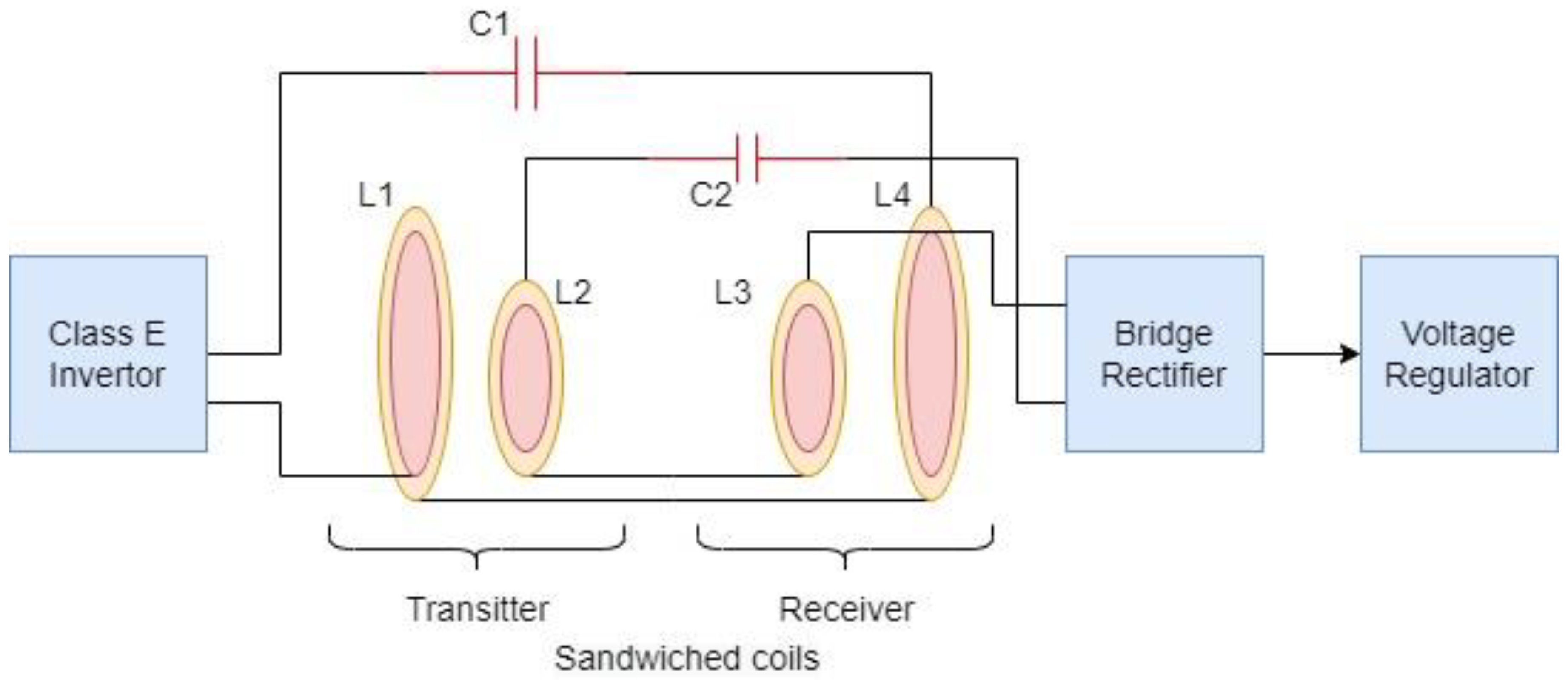
| [20] | System with sandwiched transmission coil technique | 160 kHz | Load power up to 5 W; 88% PTE; high flexibility |
|
| [21] | WPT system with switchable pi-match network | 6.78 MHz | Tr distance— up to 180 mm; Constant output voltage— 16.8 V; Efficiency: 78% | two-coil system using switchable Pi-match network. |
| [22] | The tissue channel technology | 13.9 MHz | PTE: 0.39% for 1 mm implant with depth of 5 cm in pork tissue | Uses body tissue as an energy transfer channel but implant should be in contact with tissue. |
| [23] | Transmitting coil with optimal radius ratio | 180 KHz | Up to 77% PTE | No need to utilize multi-coil adoption |
| [24] | Capacitor-segmented coils | 40.68 MHz | Up to 31% PTE; Coverage: 20 mm | SAR: 5 times lower than non-segmented coils |
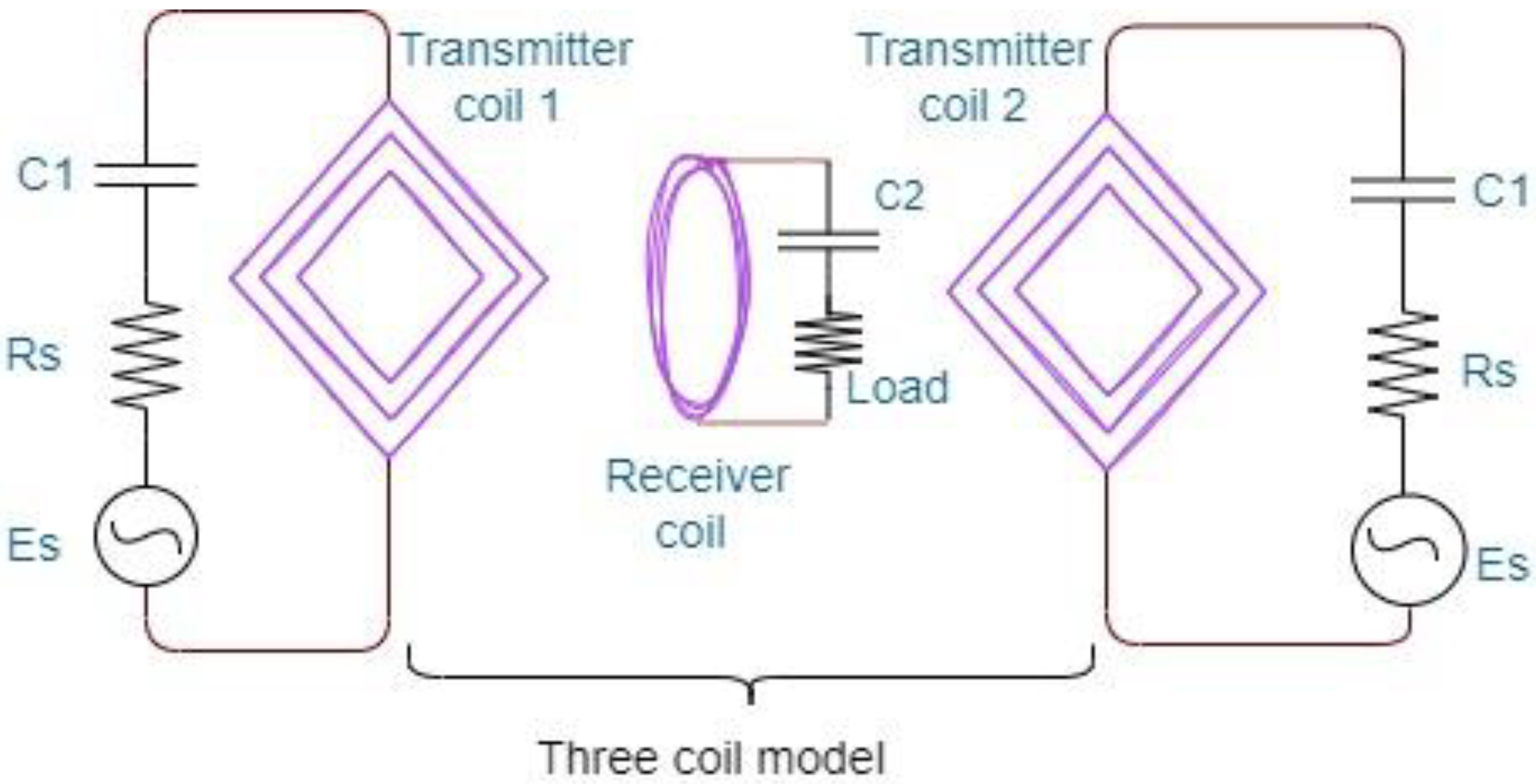
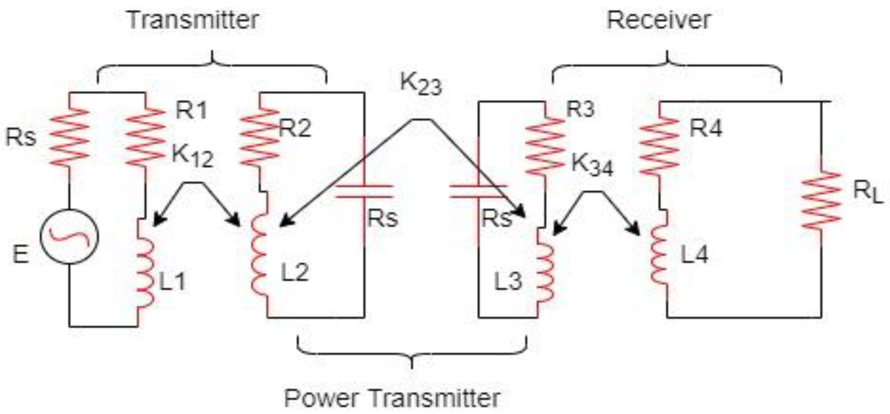
| [25] | 3-coil approach | 50 kHz | Up to 48% PTE; Power: 80 mW; Coverage: 15 cm | Memetic algorithm used |
| Ref. | Approach | Operating Frequency | Performance | Remarkable Observation |
|---|---|---|---|---|
| [29] | Impedance-matching technique in magnetic coupling resonance | 144 MHz | 46% PTE | 10 mW input power achieved without affecting power efficiency provided without using matching circuits |
| [30] | Resistive matching (complex conjugate match) with an AC boost converter | 987 kHz (Piezo-electric receiver) | AC boost method: load power = 1 mW; 74% PTE | Power transfer attained maximum level in providing ultrasonic power to IMDs |
| [31] | Titanium alloy on the WPT link | 13.56 MHz | Connection link Efficiency improved | Grade 2 gives more efficiency than Grade 5 titanium alloy. |
| [32] | Powering through 2-contact resonant capacitive link (Hybrid ASK-FSK technique) | 1 MHz | For air kapton gap of capacitive link, up to 90 mW of power and 70% PTE attained |
|
| Ref. | Approach | Operating Frequency | Performance | Remarkable Observation |
|---|---|---|---|---|
| [33] | WPT with 1X mode or 2X mode reconfigurable R3 rectifier | 13.56 MHz | Output power of 10 to 100 mW; max efficiency of 92.6% | Stable power control attained by using a data backscattering uplink technique |
| [34] | System with adjustable compensation network | 570 kHz | Constant output voltage | Components minimized@ Receiver without abating efficiency |
| [35] | Distance and load-insensitive inductive approach | Not specified | Receiver efficiency over 88%; overall PTE 76% | Automatic power adjustment attained by closed-loop control scheme; its response time is 69 ms |
| [36] | WPT with switched capacitive converter (SCC) | 13.56 MHz | Desired output: 5 V (for 1.3–3.3 V input); 57–74% efficiency |
|
| [37] | Receiver (RVM-Rx) with VPTD technique | 13.56 MHz | 67.8% efficiency @Rx | MDTL and ODTL used |
| Ref. | Approach | Operating Frequency | Performance | Remarkable Observation |
|---|---|---|---|---|
| [39] | System with dual band PIFA | 915 MHz | Boost up of directivity of antenna and radiation efficiency |
|
| [40] | Non-leaky WPT and T-shaped ground slotted antenna | 402–405 MHz (MICS) | Apprx. 4 mW power attained | Power leakage control attained using Near Field Plate |
| [41] | A triple-loop -echnique-based WPT | 13.6 MHz | 13.5% PTE at 20 mm distance coverage | A 3-coil inductive link also established to improve PTE |
| [42] | Design with Reactive near field of antenna | 2.45 GHz (ISM) | 1.8% PTE | 1.92 W/Kg SAR and Antenna misalignment issue also addressed |
| [43] | Intermodulation technique for antenna alignment | Rectenna 2T of 2.448 and 2.452 GHz; 4-MHz intermodulation | Minimizes the interference in NRIC link; Implantation depth is 2 mm. |
|
| [44] | Inductive Coupling (for BMID) | 400 MHz | −30.12 dB wireless power connection and high efficiency |
|
| [45] | New Antenna sensor (for wireless endoscopy system) | 2450 MHz | Smaller size; High gain and sensitivity; |
|
| [46] | Antenna with split resonant rings | 272 MHz to 1504 MHz; Relative Bandwidth: 138.7% | Peak gain: −32@MICS and −34@ISM |
|
Disclaimer/Publisher’s Note: The statements, opinions and data contained in all publications are solely those of the individual author(s) and contributor(s) and not of MDPI and/or the editor(s). MDPI and/or the editor(s) disclaim responsibility for any injury to people or property resulting from any ideas, methods, instructions or products referred to in the content. |
© 2022 by the authors. Licensee MDPI, Basel, Switzerland. This article is an open access article distributed under the terms and conditions of the Creative Commons Attribution (CC BY) license (https://creativecommons.org/licenses/by/4.0/).
Share and Cite
Nithiyanandam, V.; Sampath, V. Approach-Based Analysis on Wireless Power Transmission for Bio-Implantable Devices. Appl. Sci. 2023, 13, 415. https://doi.org/10.3390/app13010415
Nithiyanandam V, Sampath V. Approach-Based Analysis on Wireless Power Transmission for Bio-Implantable Devices. Applied Sciences. 2023; 13(1):415. https://doi.org/10.3390/app13010415
Chicago/Turabian StyleNithiyanandam, Vijayanandam, and Vidhya Sampath. 2023. "Approach-Based Analysis on Wireless Power Transmission for Bio-Implantable Devices" Applied Sciences 13, no. 1: 415. https://doi.org/10.3390/app13010415