Article

Design of a Power Converter for Solar Energy Storage System

Department of Electronic Engineering, National Formosa University, Huwei, Yunlin 632301, Taiwan
*
Author to whom correspondence should be addressed.
Appl. Sci. 2023, 13(10), 5897; https://doi.org/10.3390/app13105897
Submission received: 27 March 2023 / Revised: 18 April 2023 / Accepted: 9 May 2023 / Published: 10 May 2023
(This article belongs to the Special Issue Power Converters and Control Techniques)

Abstract

:
This paper presents a single-stage three-port isolated power converter that enables energy conversion among a renewable energy port, a battery energy storage port, and a DC grid port. The proposed converter integrates an interleaved synchronous rectifier boost circuit and a bidirectional full-bridge circuit into a single-stage architecture, which features four power conversion modes, allowing energy adjustment for both the renewable energy and the battery storage energy ports when power is supplied by the renewable energy port. It also features bidirectional functionality that allows the battery storage energy port to provide energy storage through the DC grid port, thereby providing uninterrupted power supply functionality. The converter uses four power switches and two inductors to boost and convert energy from the renewable energy port to the battery storage energy port or to the DC grid port through the bidirectional full-bridge circuit. The converter is also capable of 1 kW power energy conversion by utilizing an adjustable duty cycle with a fixed frequency of 100 kHz and phase-shift control through a built-in pulse width modulation control module of a TMS320F28 series digital signal processor. According to the experimental results, the converter developed in this study can achieve a conversion efficiency of up to 94%.

1. Introduction

Traditional systems for regulating electrical energy from renewable energy sources comprise multiple power converters [1]. To maintain the ability to track the maximum power point of the renewable energy port and ensure system voltage stability in the battery energy storage port, three DC-to-DC converters are required: one for converting the power of the renewable energy port and two for the energy storage and release of the battery energy storage port. An inverter is also required to convert DC to AC power to supply AC loads. Because each battery energy storage system requires a converter, the entire system requires multiple sets of converters, resulting in drawbacks such as large physical size and high costs. In [2,3], the charger and energy release converter of three converters in a traditional electrical energy regulation system for renewable energy was replaced by a bidirectional converter. Although this design allows for the tracking of when peak solar power is provided, the energy release process of the battery still requires multiple conversions [3,4,5].
Although the aforementioned system uses two DC-to-DC converters to regulate the electrical energy between the renewable energy and battery energy storage ports, it still requires multiple conversions to release energy from the battery storage port, thereby reducing system efficiency. To solve this problem, a single DC-to-DC converter with a multi-energy port design can be used to regulate electrical renewable energy to reduce the overall system volume and cost and reduce the number of energy conversions required to increase energy conversion efficiency.
The non-isolated three-port converter architecture presented in [6] features low voltage gain conversion. Although the single-stage non-isolated design has the advantages of a small circuit volume and few power components, the voltage gain is solely determined by the duty cycle of the switch and is suitable only for low DC voltage loads, such as in solar LED applications. Hence, it is not suitable for energy systems interconnected with the power grid or battery equipment that requires a high voltage gain.
In [7], an independent regenerative energy converter with a high voltage gain was proposed. This converter uses only three power switches to achieve power conversion. It also uses inductance energy storage for power conduction and transfer to achieve a high voltage conversion ratio. Although this converter can output voltages of up to 400 V, the power capacity of the circuit is rather limited. Similar circuit architectures proposed in other studies have a higher voltage gain, but they use additional inductors, which are expensive and bulky, and lack electrical isolation characteristics. Operating such circuits in high-voltage and high-power environments may compromise electrical safety.
In [8], multiple isolated three-electricity-port converters relying on various transformer induction methods were proposed to conduct electrical power. For instance, in [8], a multi-winding transformer was used to design isolated input and output ports to improve electrical safety. However, multi-winding transformers have large volumes and are associated with high costs, and they are capable of only one-way power flow control. Although transformer leakage inductance has been used in other studies to achieve zero-voltage switching in a primary-side switch and improve the conversion efficiency of converters, these converters are capable of only one-way power conversion.
In [9], multiple transformers were used to achieve bidirectional power transmission, which is applicable to energy storage systems. However, this architecture requires additional power switches, making the circuit complex and difficult to control. In [10], a similar multi-group full-bridge connection architecture and series resonance were used to achieve bidirectional power conversion and high-power transmission, which is applicable to fuel cells and other regenerative energy systems. However, this architecture increases the volume of the transformer and requires additional power switches, thereby resulting in additional costs.
In the aforementioned multi-energy port renewable energy systems, the battery energy storage ports rely solely on surplus and unused energy for energy storage when supplied only by renewable energy ports. When renewable energy ports are not supplying power and the energy storage ports are insufficiently charged, other sources of electrical energy cannot be used to charge the energy storage ports. In [10], a bidirectional three-energy-port DC-to-DC converter was proposed to combine interleaved buck and half-bridge converter structures and achieve power conversion between any two energy ports through phase-shift pulse width modulation (PWM) control. However, the half-bridge structure resulted in an unstable output voltage and low power capacity. An analysis and comparison of the full-bridge and half-bridge circuit structures with rated power in kilowatts revealed that the full-bridge structure exhibited a higher converter efficiency, even though it required more power switches and had higher costs. Therefore, in high-power applications, full-bridge converter structures can support a larger power capacity and have more voltage stability compared to half-bridge converter structures [11,12].
In [13], the topology of interleaved Buck/Boost integrated with dual active bridge (DAB) is proposed, utilizing a centralized control method using Pulse Width Modulation (PWM) control on the primary side and Phase Shift Modulation (PSM) control on the secondary side. This method enables the control of system energy, bidirectional power flow, and single-stage power conversion between different ports. In [14], a novel three-port converter is proposed based on dual active bridge topology, interfacing two DC sources and an AC output. Power flow is achieved through dual phase shift modulation and standard sine pulse width modulation is used for AC synthesis. However, neither of the aforementioned articles conducted a comprehensive efficiency analysis on various power transfer modes. Additionally, their circuit topologies all have two DC input ports and output to DC and AC loads, respectively. The power transfer modes in the previous studies only involved PV charging the battery or transferring power between two DC ports to the third port, lacking the mode of transferring power from the third port to the battery port. If this converter is to be used in the case where the third port is a DC Grid, it must have the ability to convert DC Grid power to the battery port so that the battery port can be charged from the DC Grid port even without input from renewable energy sources. This can turn the battery port into a small energy storage system for regulating electrical energy. The power converter developed in this study has the power conversion mode to transfer power from the third port (DC Grid) to the battery port, making it suitable for use on a DC Grid.
Given the advantages and disadvantages of the technologies discussed in the aforementioned literature, achieving an isolated renewable energy storage and supply system with three energy ports and a single-stage converter is both feasible and necessary. In this study, a single-stage converter with three energy ports utilizing a full-bridge circuit structure as an isolated circuit was designed and manufactured to achieve a high power conversion capacity and voltage gain. Various types of renewable energy conversion and energy storage systems discussed in [15,16,17,18] were integrated and referenced. A single-stage structure was used to increase the efficiency of multistage converters and reduce the overall converter size and material costs. The proposed converter exhibited bidirectional energy transfer functionality, allowing the energy of the battery energy storage system to be combined with the energy produced by the renewable energy generation system to achieve energy regulation, thus providing stable electricity to the DC grid [19,20,21,22].

2. Circuit Structure and Operation Model

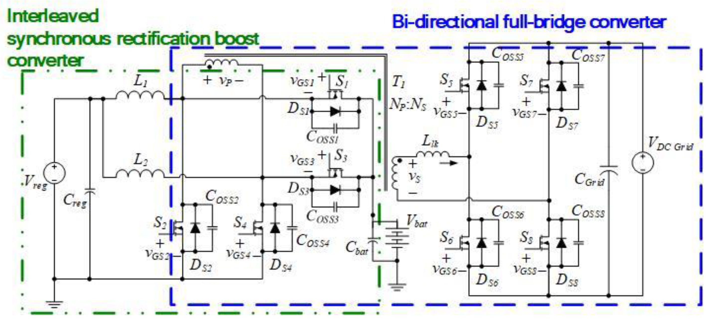
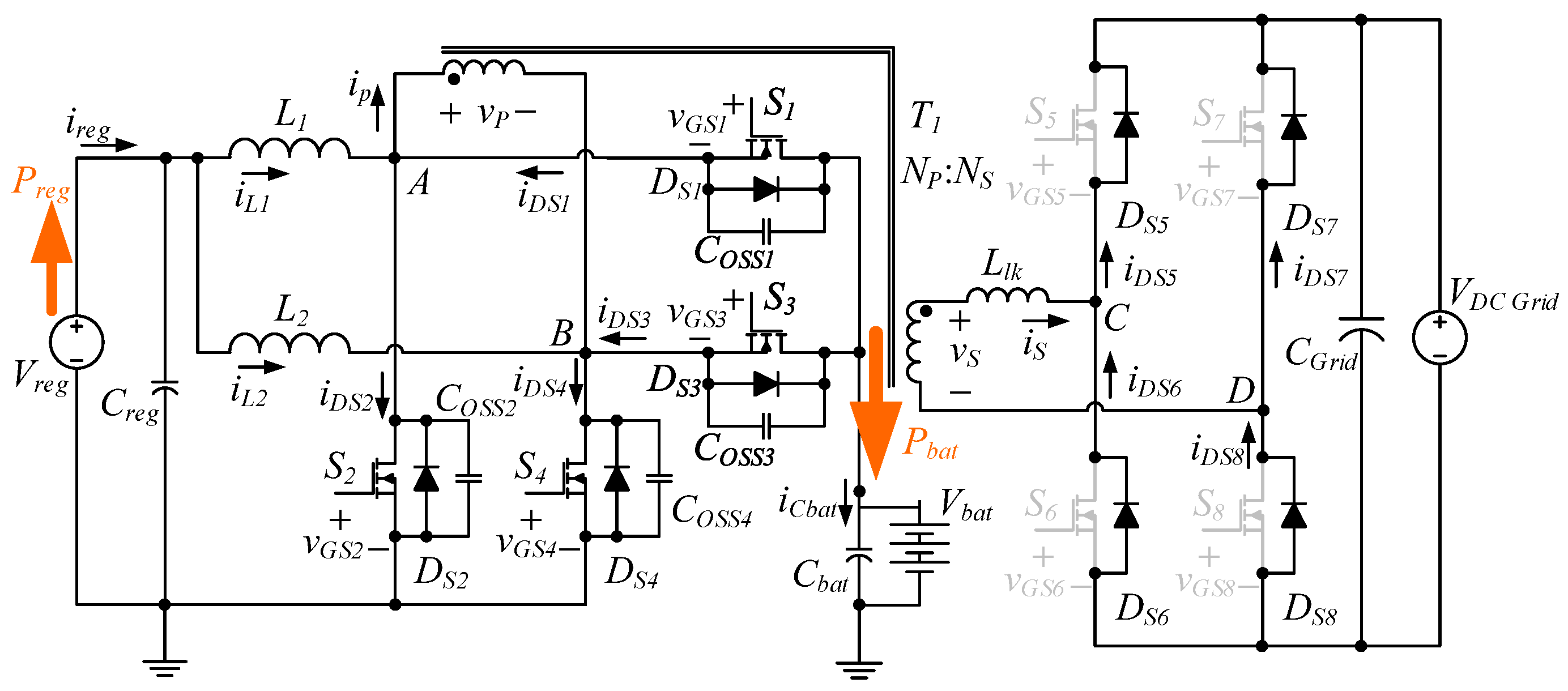
2.1. Circuit Structure

Figure 1 depicts the proposed single-stage, three-energy-port, isolated-type energy converter. This converter integrates a boost converter with interleaved synchronous rectification, a set of transformers, and a bidirectional full-bridge converter. By utilizing the interleaved synchronous rectifier converter, the renewable energy port relies on a boost-type mechanism to increase the voltage level in the energy storage and release port or directly supply energy through the converter to the DC grid. The secondary side of the transformer is a full-bridge converter that comprises four power switches cooperating with another four power switches in the primary side of the transformer to form a bidirectional full-bridge converter suitable for energy exchange between the energy storage and release port and the DC grid port. This full-bridge structure renders the circuit suitable for high-power applications, and the isolated feature of the transformer enhances the safe utilization of the DC grid. The converter has four power conversion modes: from a battery energy port to a DC grid port (B2G mode), from a DC grid port to a battery energy port (G2B mode), from a renewable energy port to a DC grid port (R2G mode), and from a renewable energy port to a battery port (R2B mode).
Additional assumptions for the analysis are made to support this circuit.
(1)
The DC grid and battery terminals are supplied with stable voltage.
(2)
The power switch only consists of the intrinsic diode D S and the parasitic capacitance C O S S , and all other parasitic components are ignored.
(3)
The inductor and capacitor are ideal components, and parasitic elements and series equivalent resistance are ignored.
(4)
The stray capacitance of the transformer is ignored; the excitation inductance L m is large enough to be ignored in its effect on the circuit.

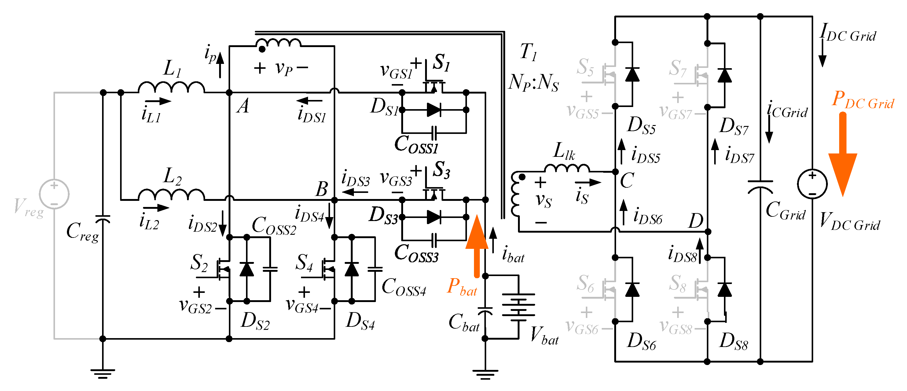
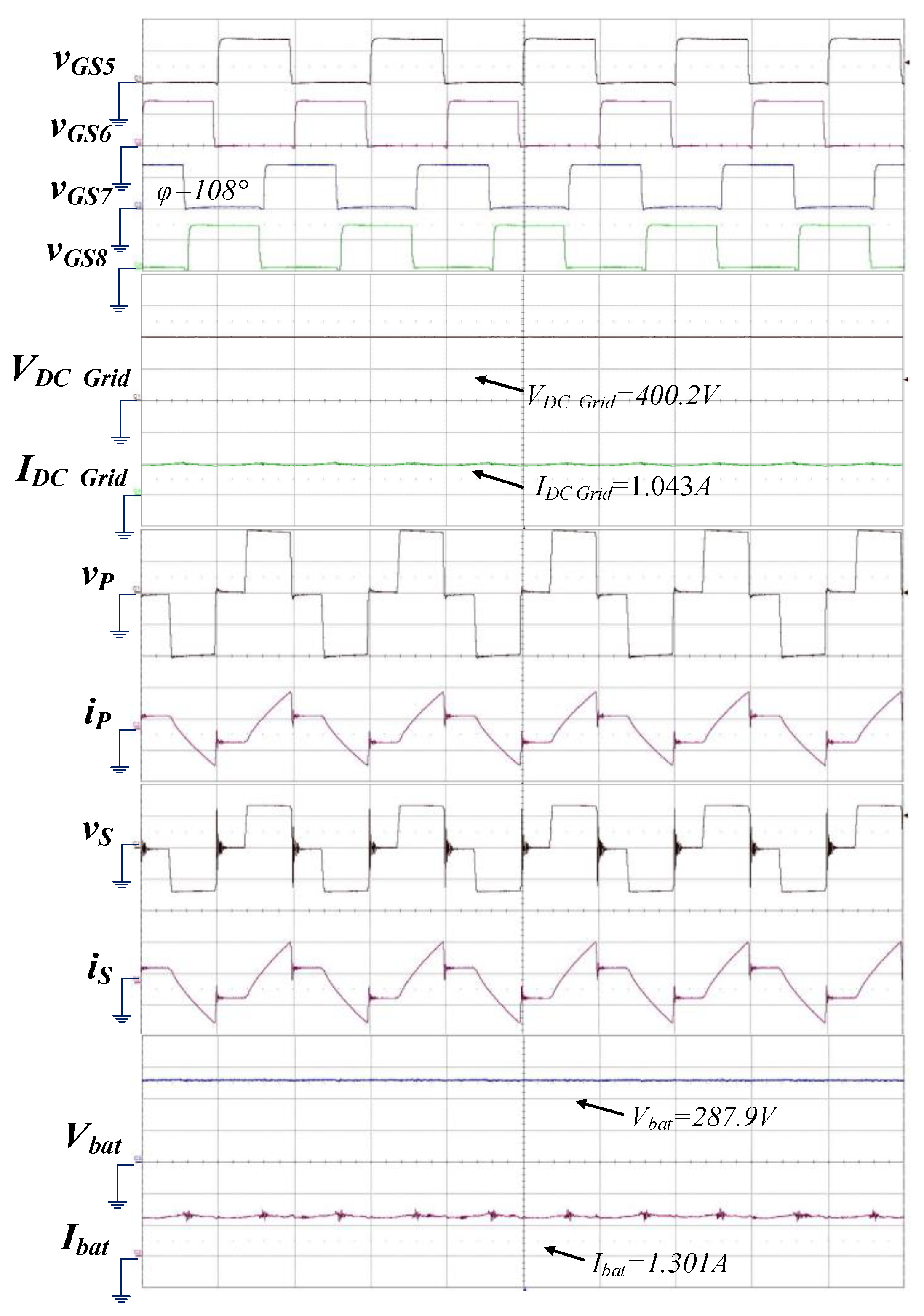
2.2. B2G Mode: Where Power from a Battery Is Supplied to a DC Grid

Figure 2 shows the circuit diagram of a battery supplying energy to a DC grid with a bidirectional full-bridge converter and a phase-shift PWM control scheme. Four power switches, namely S1, S2, S3, and S4, are driven by a fixed frequency and duty cycle. The phase-shift angle φ of the driving signals between the left arm (S3, S4) and right arm (S1, S2) is changed to control the output power. Figure 3 shows the theoretical waveforms of a battery supplying energy to a DC grid at a shift angle of 118.8°, with the voltage polarity and current flow direction defined as those in Figure 2. After the energy released by the battery storage and supply port is processed by the full-bridge power switches S1S4, an electric current flows through the transformer, and the induced energy passes through the intrinsic diodes DS5DS8, thus providing DC energy to the DC grid. Although some current passes through the inductors L1 and L2, the average current remains 0.
Figure 3 shows the theoretical waveform explanation for phase shift angle Φ = 118.8°, with Duty D = 0.5. The current flowing into the DC grid end is the rectified waveform of the secondary current i s of the transformer. The number of turns on the primary side of the transformer is N p , and the number of turns on the secondary side is N s , where the turns ratio is shown in Equation (1).
n = N S N P
Due to the symmetry control of the PWM for the positive and negative half cycles, let us first discuss the power conversion during the positive half cycle of i s , where the current i s is positive during t 3 t < t 5 and t 5 t < t 6 However, the time interval between t 5 and t 6 is very short and can be ignored, which has been confirmed in the actual measured waveform. The voltage drop across the leakage inductance L l k during this time is shown in Equation (2).
L l k · d i s d t = n V b a t V D c _ G r i d ,   t 3 t < t 5 V D C _ G r i d ,   t 5 t < t 6
The variation current of iS, calculated by Equation (2), is shown in Equation (3).
L l k · d i s d t = V s V D c _ G r i d = >   Δ i s = n V b a t V D c _ G r i d L l k · Δ t , Δ t = t 5 t 3 = φ · T 2 π = ( n V b a t V D c _ G r i d ) · φ · T L l k · 2 π
The maximum peak current of the triangular wave of iS can be calculated from Equation (3) and is shown in Equation (4), where φ is the phase shift angle, T is the operating period, and f s is the operating frequency. Ignoring the extremely short t 6 ~ t 5 interval, the average current value I D C _ G r i d can be calculated as shown in Equation (5). The average voltage value V D C _ G r i d is shown in Equation (6).
I s _ m a x = n V b a t V D c _ G r i d L l k · φ 2 π f s
I D C _ G r i d = I s _ m a x 2 = 1 2 · n V b a t V D c _ G r i d L l k · φ 2 π f s
V D C _ G r i d = 2 D · n · V b a t · 2 · φ 2 π
When Duty D = 0.5, the average power P D C   G r i d flowing into the DC grid on the secondary side is shown in Equation (7).
P D C _ G r i d = I D C _ G r i d · V D C _ G r i d
Substituting Equation (4) and Equation (6) yields:
P D C _ G r i d = 1 2 · ( n V b a t V D c _ G r i d ) · φ 2 π f s L l k · n V b a t · φ π = n V b a t · ( n V b a t V D c _ G r i d ) L l k · f s · ( φ 2 π ) 2 , 0 < φ < π

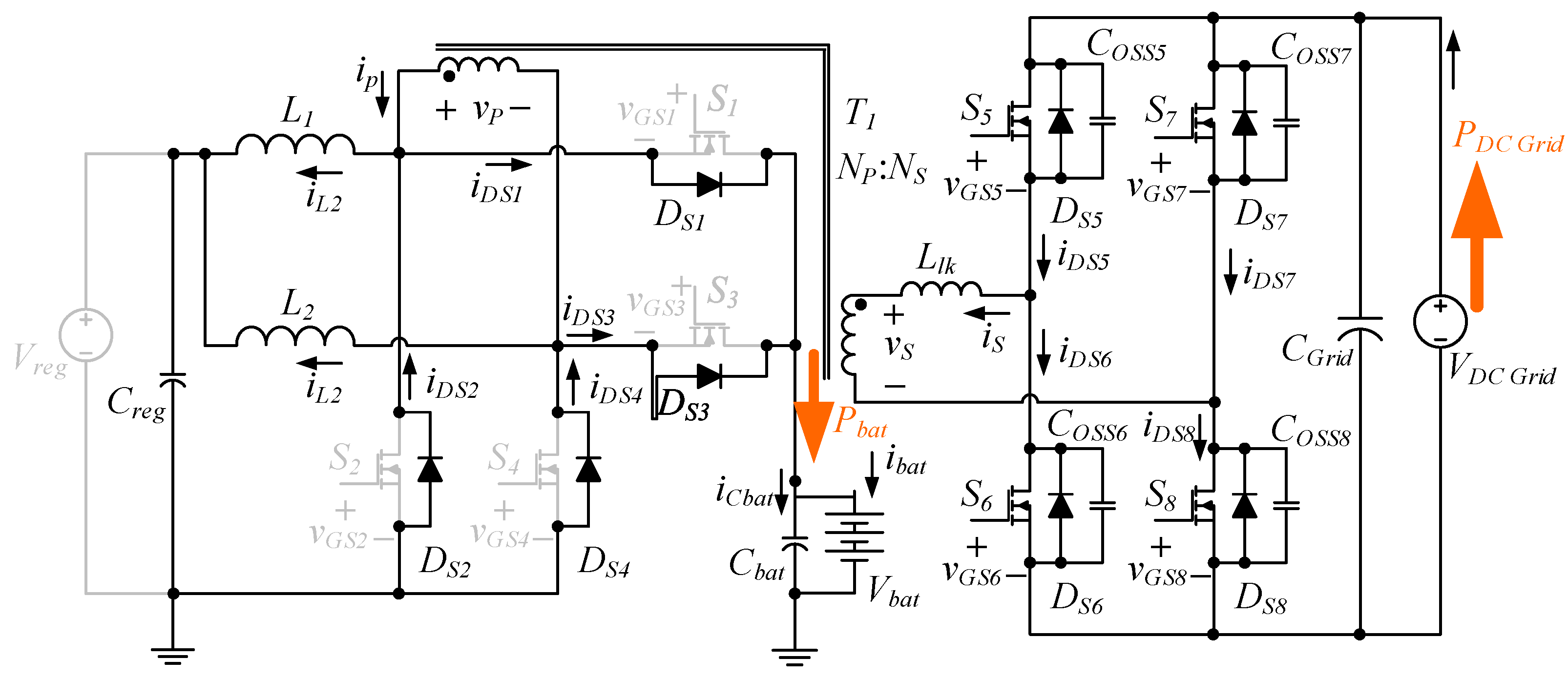
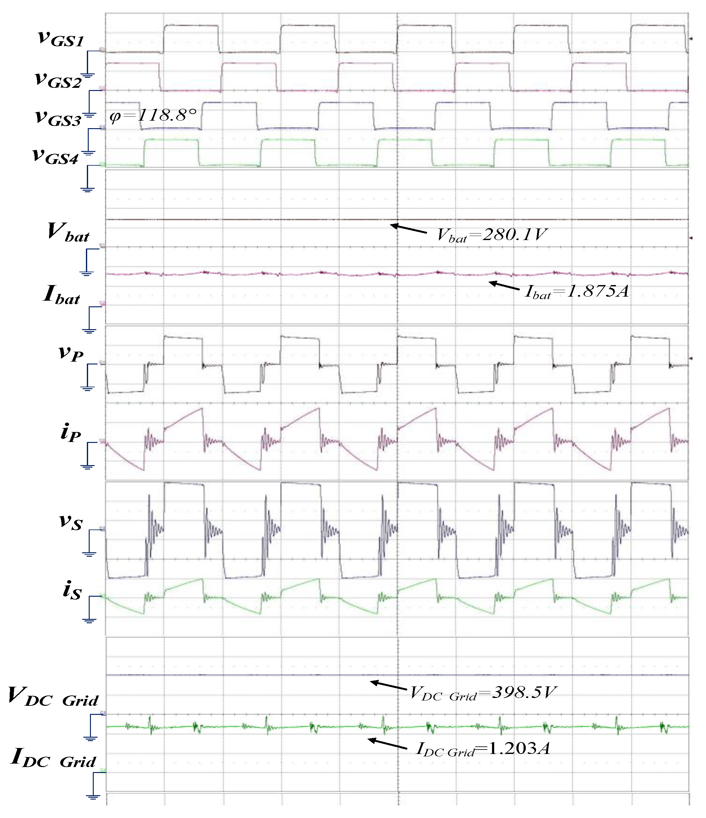
2.3. G2B Mode: Where Energy from a DC Grid Is Stored in a Battery

Figure 4 shows the circuit diagram for when energy from a DC grid is stored in a battery and presents the definitions of the voltage polarity and current flow direction. Figure 5 depicts the theoretical waveforms of a DC grid storing energy to a battery at a phase-shift angle of 108° between the left (S5, S6) and right (S7, S8) arms. In this mode, the energy supplied by the DC grid passes through the full-bridge power switches S5S8 and feeds current to the left winding of the isolated transformer. This energy is first transferred through electromagnetic induction to the right side of the transformer and then rectified by the intrinsic diodes DS1DS4, thus storing energy to the battery unit. Although some current passes through the inductors L1 and L2, the average current remains at 0.

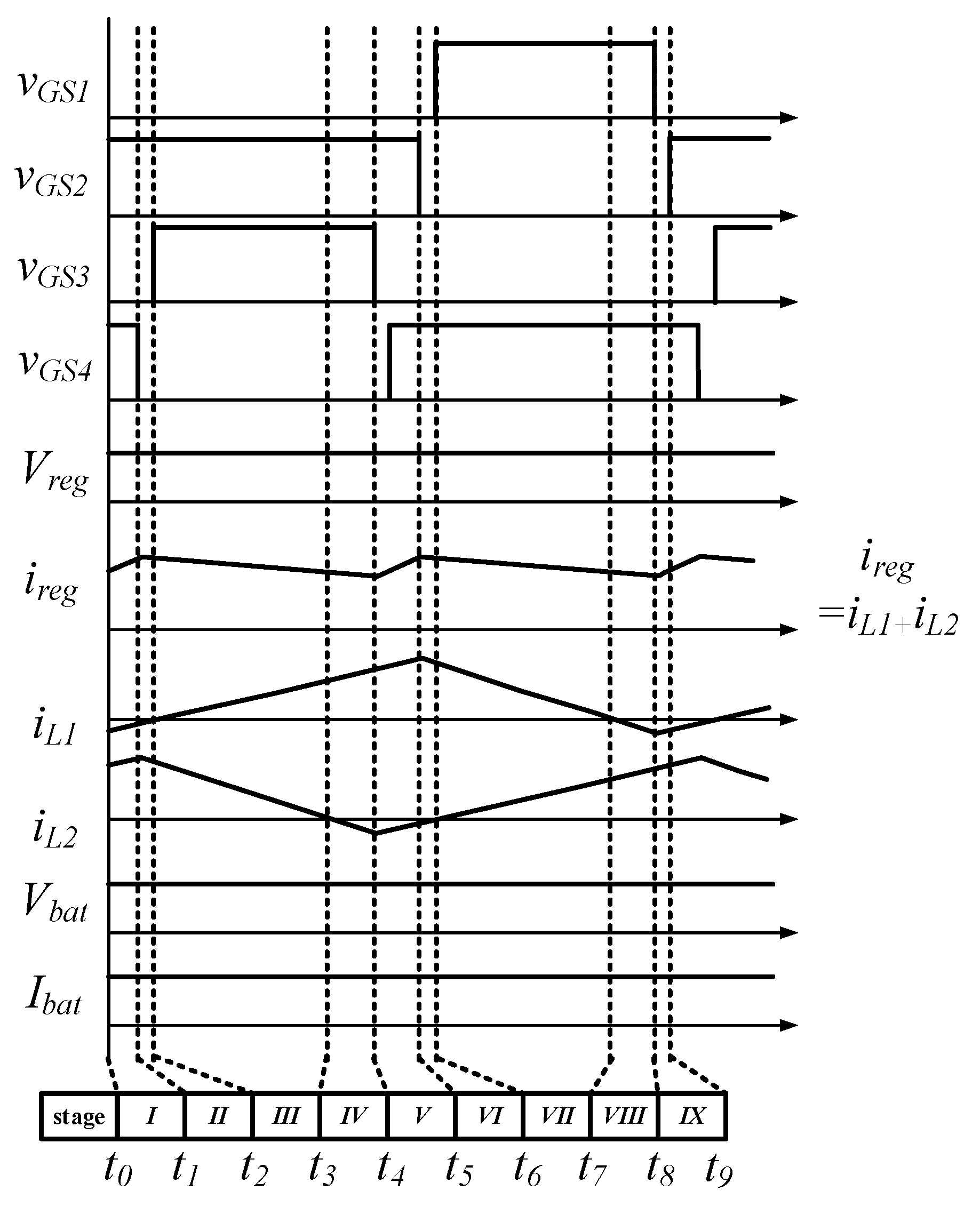
2.4. R2B Mode: Where Renewable Energy Is Stored in a Battery

Figure 6 shows the circuit diagram of a converter operating in a mode in which a renewable energy source stores energy to a battery. In this mode, two sets of synchronous boost-type rectifiers are connected in parallel, thus constituting an interleaved circuit topology. An asymmetric PWM scheme is used to control the duty cycles of the lower arm switches S2 and S4 to regulate the amount of energy stored by the inductors L1 and L2, thereby achieving output power regulation. Because the voltage of the renewable energy port fluctuates depending on the ambient conditions, this mode involves the use of an interleaved synchronous boost-type rectifier to transfer energy, and this interleaved boost-type design aids in lowering the current stress of the inductor. When the entire gating signals sent to the power switches reach 50%, the voltage of the battery port V b a t becomes approximately twice that of the renewable energy port V r e g . Hence, if the output voltage of the renewable energy port is more than twice that of the battery port, then the duty cycle of the gating signals sent to the principal power switches vGS2 and vGS4 falls below 50%. By contrast, if the output voltage of the renewable energy port is less than twice that of the battery port, then the duty cycle of the gating signals exceeds 50%.
Figure 7 depicts a scenario in which the voltage supplied by the renewable energy port is less than twice the voltage of the battery port. The theoretical waveforms demonstrate that the gating signals vGS1 and vGS2 complement each other, as do the gating signals vGS3 and vGS4. Dead time zones are incorporated into the gating signals to prevent shooting through, and the duty cycle exceeds 50%. All voltage polarities and current flow directions are defined in Figure 6. The energy from the renewable energy port is converted and transmitted to the battery unit through power switches S1S4 and the voltage is increased by L1 and L2.
For the mode in which renewable energy is stored in the battery, only the interleaved synchronous rectifier is active. Although a small amount of energy is induced on the DC grid side, this amount is negligible. As expressed in Equation (8), the equation form for the renewable energy port voltage V r e g and battery port voltage V b a t with respect to the duty cycle D of switches S2 and S4 is similar to that of a boost converter. Thus, adjusting the duty cycle D may affect the energy storage time of L1 and L2 and the battery port voltage.
V b a t = V r e g 1 D

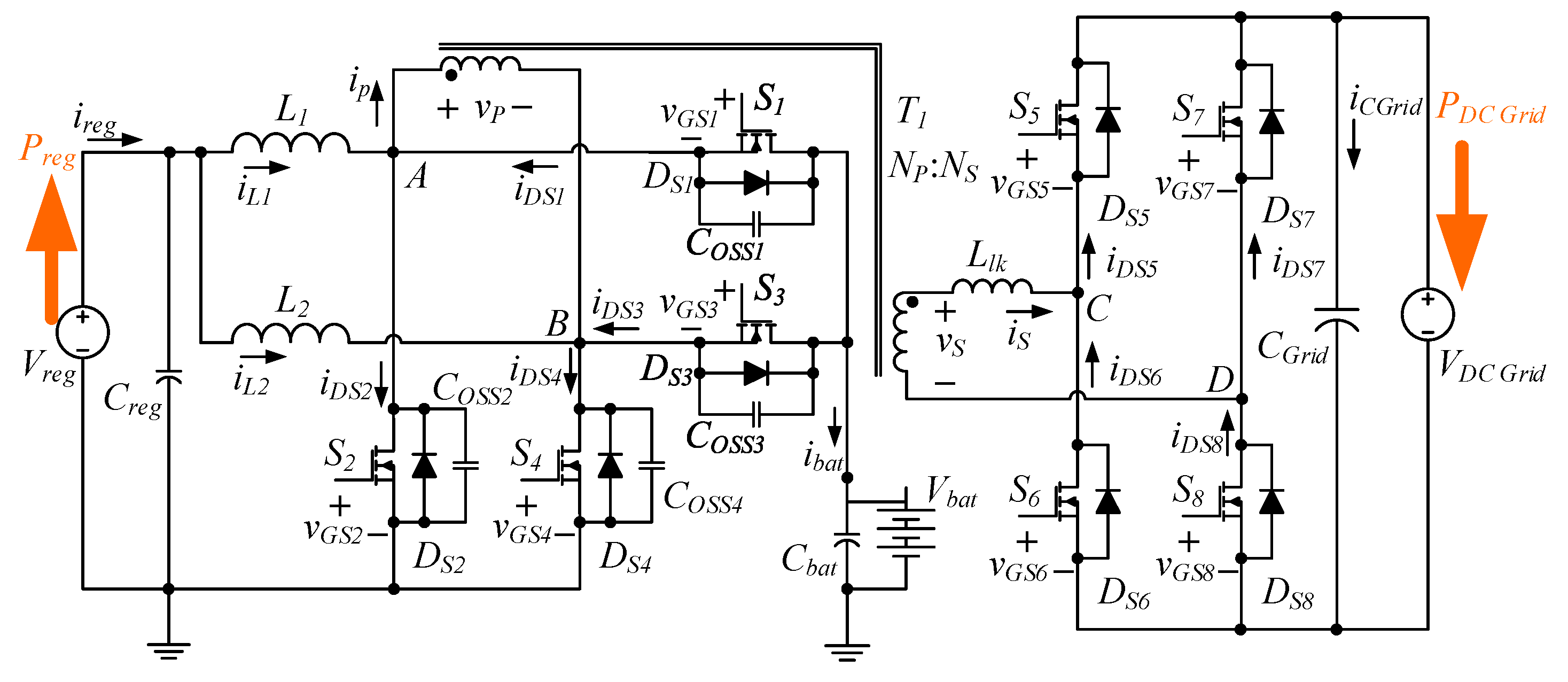
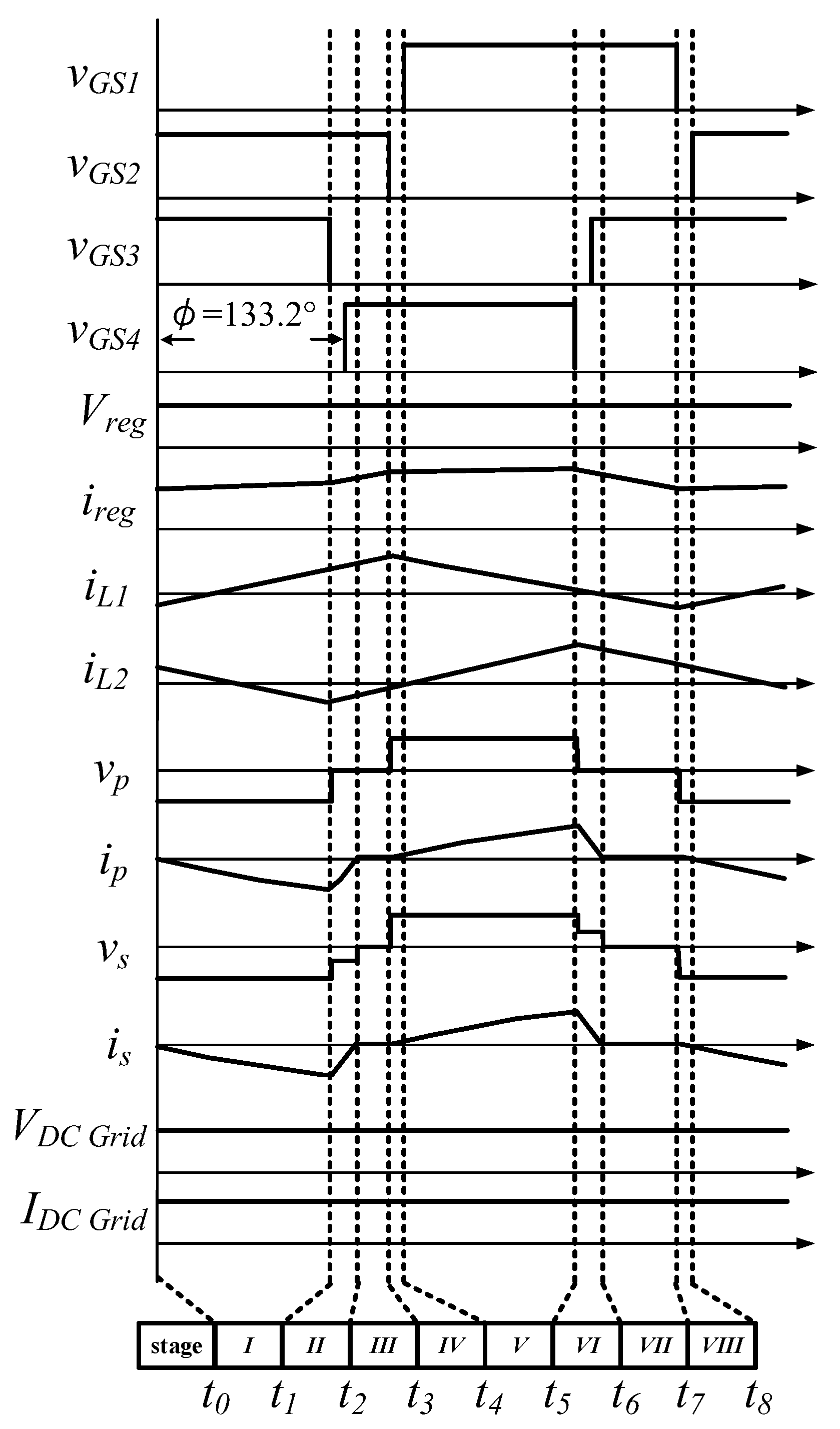
2.5. R2G Mode: Where Renewable Energy Is Supplied to a DC Grid

Figure 8 shows the circuit diagram for a mode in which renewable energy is supplied to the DC grid. The converter circuit is a combination of an interleaved boost-type converter, a transformer, and a full-bridge rectifier. The theoretical waveform is illustrated in Figure 9. The phase-shift angle between the left arm (S1, S2) and right arm (S3, S4) is set to 133.2°. When the renewable energy source transfers energy to the DC grid, the battery storage unit must be ready to compensate for the intermittent nature of the renewable energy unit. Therefore, the battery unit is connected in advance.
The voltage of the external battery is assumed to be V b a t , C , which is identical to the voltage of the battery port. According to Equations (9) and (10), the average output power is 0, despite current flowing inside the battery unit. Therefore, the renewable energy source supplies energy to the DC grid. Depending on the relationship between the renewable energy unit and the floating voltage of the battery, the duty cycle D of this mode is either greater than or less than 50%. The gating signals responsible for changing the phase angle control the output energy transferred from the renewable energy unit to the DC grid.
V b a t , C = V r e g 1 D = V b a t
V b a t = V b a t , C V b a t = 0

3. Design and Experimental Results

3.1. Specifications and Parameter Design

Table 1 lists the electric component parameters used in the experiment. The rated conversion power was 1 kW, and the switching frequency of the power switches was fixed at 100 kHz. In addition to emphasizing the performance of the bidirectional isolated DC-to-DC converter, matching a practical solar panel with an appropriate energy storage battery was a serious challenge.
The parameter values for the main components of the power converter designed in this study are described below.
(1)
Inductor design for boost converter L1 and L2
In this scenario, an interleaved boost converter is used. The input has two inductors sharing the input current. Thus, the input current is composed of iL1 and iL2. Under optimal conditions, iL1 is equal to iL2. The relationship between the input power and inductance can be derived from the inductor current and input voltage. Therefore, the inductance value must be obtained. To ensure that the converter can operate when renewable energy is charged to the battery, L1, L2, and the parasitic capacitor COSS can form a resonant circuit to achieve zero voltage switching(ZVS) for four switches at the primary side. The inductor current must be designed in discontinuous conduction mode (DCM), and all switches must meet the condition in Equation (12) to achieve ZVS easily.
i m i n = ( 2 · C O S S ) · V b a t 2 L l k
i d s 1 = i L 1 , m a x i P > i m i n ,   f o r   S 1 i d s 2 = i L 1 , m i n i p < i m i n ,   f o r   S 2 i d s 3 = i L 2 , m a x i p > i m i n ,   f o r   S 3 i d s 4 = i L 2 , m i n i p < i m i n ,   f o r   S 4
According to voltage-second balancing theory, the average voltage v L is 0 during a complete switching period. The discharging time of the inductor is derived as follows:
1 D T = D T · V r e g V b a t V r e g
The average inductor current i L , a v g in a switching period is related to V r e g , V b a t , and the duty cycle D and is expressed as follows:
i L , a v g = V r e g 2 L × D T × ( D + D · V r e g V b a t V r e g )
This circuit has two inductors sharing the input current. The input current I r e g is the sum of iL1, avg and iL2, avg. Under optimal conditions, iL1, avg = iL2, avg = iL, avg. Hence, as expressed in Equation (15), I r e g can be set to twice the value of iL, avg. As expressed in Equation (16), the average power of the converter can be derived by summarizing Equations (13)–(15). In addition, the inductance of L1 and L2 can be determined. As expressed in Equation (17), the inductance L is approximately 87.6   μ H . To ensure that the switches achieve ZVS, the practical inductance is 81 μ H .
I r e g = 2 × I L , a v g
P r e g = V r e g 2 × D 2 L × f s × ( 1 + V r e g V b a t V r e g )
L = V r e g 2 × D 2 × η P b a t × f s × ( 1 + V r e g V b a t V r e g )
(2)
Design of Cbat
Equation (18) shows the relationship between Cbat and v C b a t . According to this equation, C b a t   i s   a p p r o x i m a t e l y   85.7   μ F . The proposed converter is suitable for use with batteries or high-capacity storage equipment. In this experiment, a 330- μ F capacitor was selected.
C b a t D R ( V b a t V b a t ) · f s
(3)
Design for the turn ratio of the transformer
The turn ratio can be determined as follows:
n = N S N P = V D C   G r i d 2 · D m a x · V b a t , m i n 1.678
(4)
Design of the leakage inductor
The converter operates when the DC grid charges the battery. By utilizing the continuity of the inductor, the switches turn off during the dead time. Both Llk and COSS assist in the resonance process for ZVS. However, to easily achieve ZVS, Llk must have a sufficiently high value. Therefore, the minimum value of Llk can be calculated as follows:
L l k 2 · 1 n 2 · V D C   G r i d 2 · C O S S I b a t
The MOSFET used in the converter is manufactured by Cree (model number C2M0160120D). According to the datasheet, the parasitic capacitor C O S S   i s   a p p r o x i m a t e l y   50   p F . Therefore, the leakage inductor L l k 1.5   μ H . When the switches turn off, the parasitic capacitors and leakage inductor of the transformer begin to resonate. To facilitate ZVS in the charger, a higher leakage inductor is required. For the purposes of this experiment, L l k = 16   μ H .
(5)
Design of CGrid
Equation (18) shows the relationship between CGrid, v C G r i d , and ΔiLlk. In this equation, 65 × 10 6 is the equivalent series resistance (ESR) of the electrolyte capacitor. After the converter parameters are substituted into Equation (21), CGrid can be calculated using Equation (22), where v C G r i d is set to 0.05% VDC Grid. Thus, C G r i d is approximately 532.4   μ F In this experiment, 810 μ F / 500 V was used.
C G r i d = i L l k v C G r i d × ( 1 16 × f s + 65 × 10 6 )
C G r i d = 4 0.2 × ( 1 16 × 100 k H z + 65 × 10 6 ) 532.4 μ F
Table 2 lists the device parameters selected for practical implementation. To achieve predetermined phase-shift PWM control for the adjustable duty cycle, a TMS320F28335 control chip from Texas Instruments (Dallas, TX, USA) was used. To drive the power switches, the gating signals were directly created using software.

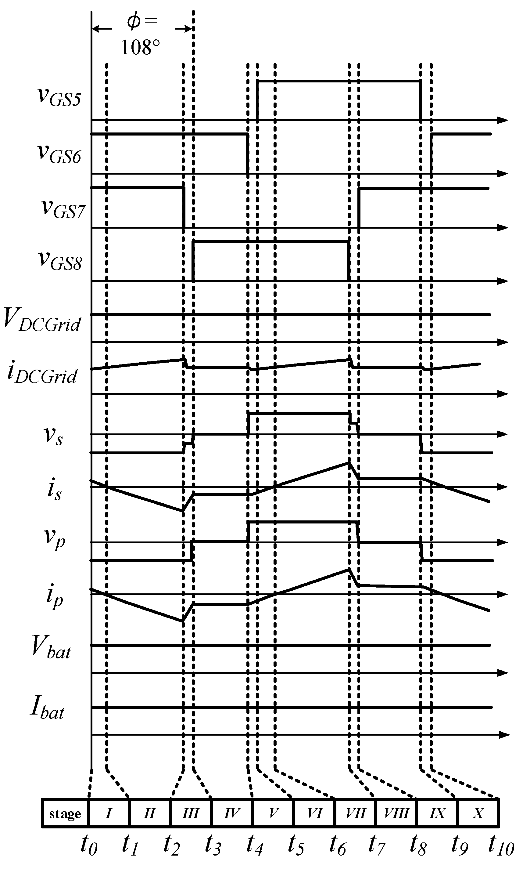
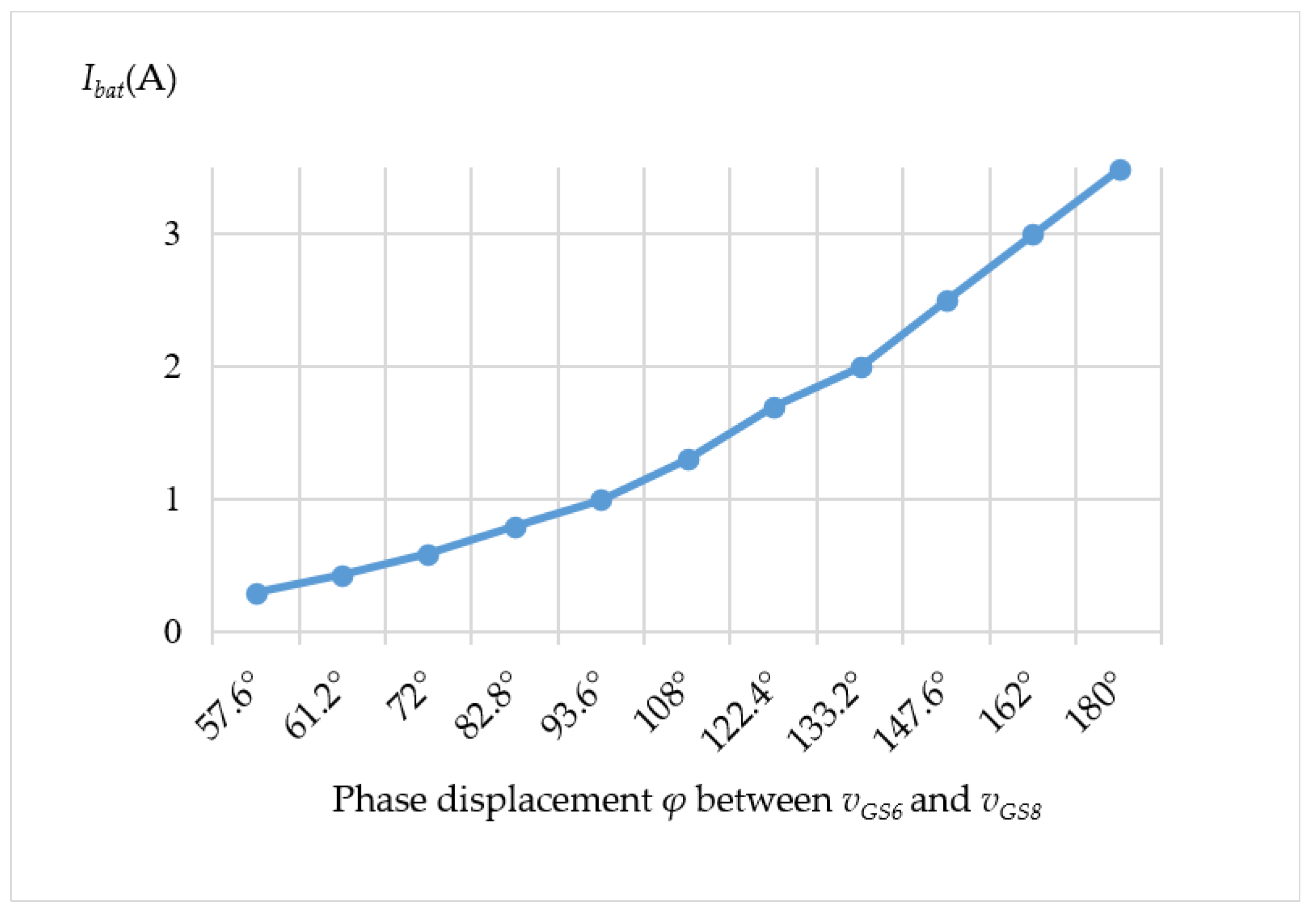
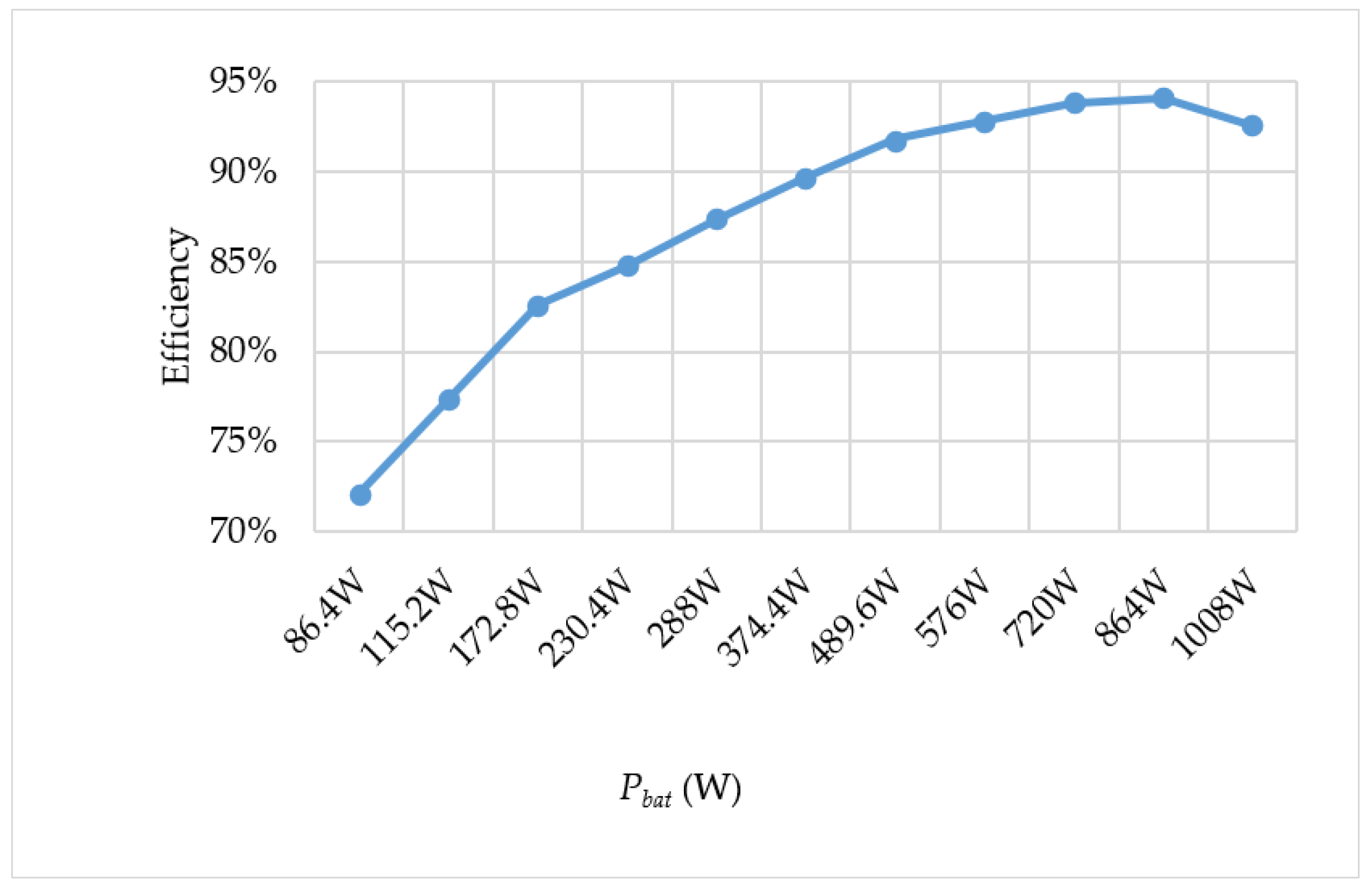
3.2. Experimental Waveforms and Measurements

The actual measured waveform of the DC grid port supplied by the battery port, with a phase shift angle φ of 118.8 degrees, is shown in Figure 10. This figure includes the trigger control signals of four switches, battery voltage, battery output current, voltage and current on both sides of the transformer, and the DC port voltage and incoming DC port current. It can be seen from Figure 10 that the battery terminal voltage V b a t is 280.1 V, the average current flowing out of the battery terminal I b a t is 1.875 A, the DC port voltage is 398.5 V, and the average current flowing into the DC port is 1.203 A. The converter efficiency can be obtained by Equation (23), and the calculated result is 91.2% in this experiment. The current flowing into the DC port under different phase shift angle operations is shown in Figure 11. Finally, the relationship between the conversion power and efficiency of the DC grid port supplied by different battery voltages is shown in Figure 12.
η = P D C   G r i d P b a t = V D C   G r i d × I D C   G r i d V b a t × I b a t = 398.5 × 1.203 280.1 × 1.875 = 479.39 525.19 = 91.2 %
Figure 13 shows the actual measured waveform of the battery port stored from the DC grid port, with a phase shift angle φ of 108 degrees. According to this figure, the DC port voltage is 400.2 V, the average current flowing out of the DC port is 1.043 A, the battery terminal voltage V b a t is 287.9 V, and the average current I b a t flowing into the battery terminal is 1.301 A. The converter efficiency is 89.7%—calculated by Equation (24). The current flowing into the battery port under different phase shift angle operations is shown in Figure 14. Finally, the relationship between the conversion power and efficiency of energy storage with different battery voltages is shown in Figure 15.
η = P b a t P D C _ G r i d = V b a t × I b a t V D C _ G r i d × I D C _ G r i d = 287.9 × 1.301 400.2 × 1.043 = 374.55 417.40 = 89.7 %
Figure 16 displays the waveform of the stored energy from the renewable energy port to the battery port, with a duty cycle of 53.3%. This waveform exhibits that the renewable energy port voltage is 140.0 V and the average current leaving the port is 3.719 A. Moreover, the battery terminal voltage V b a t is 287.4 V, and the average current flowing into the battery port is 1.703 A. The converter efficiency is 94%—calculated by Equation (25). The current flowing into the battery port under different duty cycles is shown in Figure 17. Finally, the relationship between the conversion power and efficiency of different energy stored from the renewable energy port is shown in Figure 18.
η = P b a t P r e g = V b a t × I b a t V r e g × I r e g = 287.4 × 1.703 140.0 × 3.719 = 489.44 520.66 = 94 %
Figure 19 illustrates the actual measured waveform that represents the transfer of energy from the renewable energy port to the DC port. The waveform has a phase shift angle of 133.2° and a duty cycle of 44%. The information presented in Figure 19 indicates that the regenerative energy port voltage is 170.2 V, with an average current of 6.426 A flowing out of the port. Similarly, the DC port voltage is 287.4 V, with an average current of 1.703 A flowing into the port. Additionally, the converter efficiency is calculated using Equation (26) and is found to be 92.2%. Under different phase shift angle operations, the magnitude of the current flowing into the DC port is shown in Figure 20. Finally, the relationship between the conversion power and efficiency of different regenerative energy ports supplying the DC port is shown in Figure 21.
η = P D C _ G r i d P r e g = V D C _ G r i d × I D C _ G r i d V r e g × I r e g = 402.4 × 2.508 170.2 × 6.426 = 1009.21 1093.70 = 92.2 %

4. Conclusions

This paper presents a single-stage, three-energy-port, isolated-type energy converter that integrates an interleaved synchronous boost rectifier and a bidirectional full-bridge circuit into a single-stage energy converter topology. The proposed energy converter enables bidirectional energy transfer between the battery, DC grid, and renewable energy sources. In this study, a 1-kW three-port converter was constructed. The paper provides a detailed and comprehensive analysis of various power conversion modes, and experimental measurements show that the energy conversion efficiency of the converter can reach 94%. Additionally, the converter can operate simultaneously in all three energy ports. The following are the advantages of the proposed converter:
  • The interleaved synchronous boost rectifier can increase the voltage of the renewable energy unit to match that of the battery unit. In addition, the converter can increase the voltage of the renewable energy and process it through a full-bridge circuit to transfer energy to the DC grid.
  • The bidirectional full-bridge topology includes a battery storage unit and a DC grid with a bidirectional energy propagation and electrical isolation capability, thereby effectively enhancing electricity usage security and increasing the power capacity of the converter.
  • With the bidirectional function of the converter, the battery unit can continuously supply energy to the DC grid when the renewable energy unit fails to do so, thereby providing an uninterruptible power supply.
  • The power conversion mode of the developed converter has a G2B mode, which allows the battery port to be charged by the DC Grid port when there is no input from renewable energy sources. This makes the battery port a small energy storage system that can regulate electrical energy.
For future studies, the number of ports on the converter in this study could be expanded to develop a multi-functional port DC converter with a miniature solar power generation system. This converter would enable the conversion of electrical energy between the solar power generation port, solar cell port, DC power port, and electric vehicle charging port. By allowing for the mutual exchange of power between these energy ports, the converter would enhance its ability to regulate and schedule stored solar energy. Additionally, to ensure maximum efficiency of the converter under variable solar conditions, the maximum power tracking function of the converter will have to be strengthened.

Author Contributions

Conceptualization, Y.-N.C. and Y.-Y.W.; methodology, Y.-H.Y. and Y.-N.C.; software, Y.-H.Y. and Y.-Y.W.; writing—original draft preparation, Y.-H.Y. and Y.-Y.W.; writing—review and editing, Y.-H.Y. and Y.-N.C. All authors have read and agreed to the published version of the manuscript.

Funding

This research received no external funding.

Institutional Review Board Statement

Not applicable.

Informed Consent Statement

Not applicable.

Data Availability Statement

Not applicable.

Conflicts of Interest

The authors declare no conflict of interest.

References

  1. Ma, Z.; Pesaran, A.; Gevorgian, V.; Gwinner, D.; Kramer, W. Energy Storage, Renewable Power Generation, and the Grid: NREL Capabilities Help to Develop and Test Energy-Storage Technologies. IEEE Electrif. Mag. 2015, 3, 30–40. [Google Scholar] [CrossRef]
  2. Su, G.-J.; Tang, L. A Bidirectional, Triple-Voltage DC-DC Converter for Hybrid and Fuel Cell Vehicle Power Systems. In Proceedings of the Applied Power Electronics Conference, Anaheim, CA, USA, 25 February–1 March 2007; pp. 1043–1049. [Google Scholar]
  3. Su, G.J.; Cunningham, J.P.; Tang, L. A Reduced-Part, Triple-Voltage DC-DC Converter for Electric Vehicle Power Management. In Proceedings of the Power Electronics Specialists Conference, Orlando, FL, USA, 17–21 June 2007; pp. 1989–1994. [Google Scholar]
  4. Al-Soeidat, M.; Khawaldeh, H.; Lu, D.D.; Zhu, J. A Novel High Step-up Three-Port Bidirectional DC/DC Converter for PV-Battery Integrated System. In Proceedings of the 2020 IEEE Applied Power Electronics Conference and Exposition (APEC), New Orleans, LA, USA, 15–19 March 2020; pp. 3352–3357. [Google Scholar]
  5. Liu, X.; Huang, J.; Li, G.; Ma, P.; Tong, X. Hybrid Pulse Frequency and Width Modulation scheme for Three-Port Resonant DC/DC Converters. In Proceedings of the IECON 2020 The 46th Annual Conference of the IEEE Industrial Electronics Society, Singapore, 18–21 October 2020; pp. 4619–4623. [Google Scholar]
  6. Vazquez, N.; Sanchez, C.M.; Hernandez, C.; Vazquez, E.; Lesso, R. A Three-Port Converter for Renewable Energy Applications. In Proceedings of the ISIE, Gdansk, Poland, 27–30 June 2011; pp. 1735–1740. [Google Scholar]
  7. Alves, D.B.; Praça, P.P.; Oliveira, D.S.; Barreto, L.H.; de Freitas, L.C. A Single-Stage Three-Port Boost Converter with High Voltage Gain Based on the Bidirectional Version of the Three-State Switching Cell. In Proceedings of the APEC, Charlotte, NC, USA, 15–19 March 2015; pp. 1934–1940. [Google Scholar]
  8. Hu, Y.; Xiao, W.; Cao, W.; Li, B.; Morrow, D.J. Three-port DC–DC converter for stand alone photovoltaic systems. IEEE Trans. Power Electron. 2015, 30, 3068–3076. [Google Scholar] [CrossRef]
  9. Wang, Z.; Li, H. An Integrated Three-Port Bidirectional DC–DC Converter for PV Application on a DC Distribution System. IEEE Trans. Power Electron. 2012, 28, 4612–4624. [Google Scholar] [CrossRef]
  10. Krishnaswami, H.; Mohan, N. Three-port series-resonant DC-DC converter to interface renewable energy sources with bidirectional load and energy storage ports. IEEE Trans. Power Electron. 2009, 24, 2289–2297. [Google Scholar] [CrossRef]
  11. Peiwen, H.; Alireza, K. Comprehensive Analyses and Comparison of1 kW Isolated DC–DC Converters for Bidirectional EV Charging Systems. IEEE Trans. Transp. Electrif. 2017, 3, 147–156. [Google Scholar]
  12. Sundar, T.; Umapathy, K. Performance Comparison of PV based Buck Boost and Interleaved Buck Boost Converter Inverter based Solar Systems. Indian J. Sci. Technol. 2017, 10, 1–7. [Google Scholar] [CrossRef]
  13. Wang, J.; Tan, W.; He, D.; Jia, L. Three Ports Bidirectional DC Converters of the Interleaved Buck/Boost Integrated with Dual Active Bridge. In Proceedings of the 2021 IEEE 4th International Electrical and Energy Conference (CIEEC), Wuhan, China, 28–30 May 2021; pp. 1–6. [Google Scholar] [CrossRef]
  14. Bhattacharjee, A.; Batarseh, I. An Interleaved Boost and Dual Active Bridge Based Three Port Microinverter. In Proceedings of the 2020 IEEE Applied Power Electronics Conference and Exposition (APEC), New Orleans, LA, USA, 15–19 March 2020; pp. 1320–1326. [Google Scholar] [CrossRef]
  15. Jordehi, A.R. Enhanced Leader Particle Swarm Optimisation (ELPSO): An Efficient Algorithm for Parameter Estimation of Photovoltaic (PV) Cells and Modules. In Solar Energy at Science Direct; Elsevier: Amsterdam, The Netherlands, 2018; pp. 78–87. [Google Scholar]
  16. Evode, R. Modeling of Electric Grid Behaviors having Electric Vehicle charging stations with G2V and V2G Possibilities. In Proceedings of the 2021 International Conference on Electrical, Computer, Communications and Mechatronics Engineering (ICECCME), Mauritius, Mauritius, 7–8 October 2021; pp. 1–5. [Google Scholar]
  17. Ghobadzadeh, A.M.; Bathaei, S.M.T.; Keshavarz-Mohammadiyan, A. Peak Shaving and Valley Filling in Distribution Network Using Electric vehicles. In Proceedings of the 2020 28th Iranian Conference on Electrical Engineering (ICEE), Tabriz, Iran, 4–6 August 2020; pp. 1–6. [Google Scholar]
  18. Singh, S.; Manna, S.; Mansoori, M.I.H.; Akella, A.K. Implementation of Perturb & Observe MPPT Technique Using Boost Converter in PV System. In Proceedings of the 2020 International Conference on Computational Intelligence for Smart Power System and Sustainable Energy (CISPSSE), Keonjhar, India, 29–31 July 2020; pp. 1–4. [Google Scholar]
  19. Chen, X.; Batarseh, I. A Three-Port Bidirectional LLC Resonant Converter for PV/Battery Applications. In Proceedings of the 2021 IEEE Applied Power Electronics Conference and Exposition (APEC), Phoenix, AZ, USA, 14–17 June 2021; pp. 632–639. [Google Scholar]
  20. Tang, X.; Wu, H.; Hua, W.; Yu, Z.; Xing, Y. Three-Port Bidirectional Series-Resonant Converter with First-Harmonic-Synchronized PWM. IEEE J. Emerg. Sel. Top. Power Electron. 2021, 9, 1410–1419. [Google Scholar] [CrossRef]
  21. Yuan, Y.; Tong, X.; Huang, J.; Zhang, W.; Xiao, J.; Koh, L.H. Power Flow Analysis of Three-Port Resonant DC Transformer and Discussion on Phase Shift Control. In Proceedings of the 2020 15th IEEE Conference on Industrial Electronics and Applications (ICIEA), Kristiansand, Norway, 9–13 November 2020; pp. 1242–1247. [Google Scholar]
  22. Ebadpour, M. A Multiport Isolated DC-DC Converter for Plug-in Electric Vehicles Based on Combination of Photovoltaic Systems and Power Grid. In Proceedings of the 2021 12th Power Electronics, Drive Systems, and Technologies Conference (PEDSTC), Tabriz, Iran, 2–4 February 2021; pp. 1–5. [Google Scholar]
Figure 1. Proposed single-stage, three-energy-port, isolated-type energy converter.
Applsci 13 05897 g001
Figure 2. Circuit diagram of B2G mode.
Applsci 13 05897 g002
Figure 3. Theoretical waveforms for B2G mode.
Applsci 13 05897 g003
Figure 4. Circuit diagram for D2B mode.
Applsci 13 05897 g004
Figure 5. Theoretical waveforms for D2B mode.
Applsci 13 05897 g005
Figure 6. Circuit diagram for R2B mode.
Applsci 13 05897 g006
Figure 7. Theoretical waveforms for R2B mode with D > 50%.
Applsci 13 05897 g007
Figure 8. Circuit diagram for R2D mode.
Applsci 13 05897 g008
Figure 9. Theoretical waveforms for R2D mode.
Applsci 13 05897 g009
Figure 10. Practically measured current and voltage waveforms for B2D mode at Vbat = 280 V. vGS1, vGS2, vGS3, and vGS4: 10 V/div; Vbat, vP, vS, and VDC Grid: 200 V/div; iP and iS: 5 A/div; Ibat: 1 A/div; and IDC Grid: 0.5 A/div.
Applsci 13 05897 g010
Figure 11. Power regulation curve in the B2D mode.
Applsci 13 05897 g011
Figure 12. Efficiency curve in the B2D mode.
Applsci 13 05897 g012
Figure 13. Current and voltage waveforms measured during the operation of the converter in the D2B mode. (vGS5, vGS6, vGS7, and vGS8: 10 V/div; VDC Grid, vP, vS, and Vbat: 200 V/div; IDC Grid and Ibat: 1 A/div; iP and iS: 5 A/div).
Applsci 13 05897 g013
Figure 14. Energy regulation curve for the D2B mode.
Applsci 13 05897 g014
Figure 15. Conversion efficiency curve for the D2B mode.
Applsci 13 05897 g015
Figure 16. Current and voltage waveforms measured in the R2B mode at Vreg = 140 V. (vGS1, vGS2, vGS3, and vGS4: 10 V/div; Vreg and Vbat: 100 V/div; Ibat: 2 A/div; Ireg, iL1, and iL2: 5 A/div).
Applsci 13 05897 g016
Figure 17. Energy regulation curve for the R2B mode.
Applsci 13 05897 g017
Figure 18. Conversion efficiency curve for the R2B mode.
Applsci 13 05897 g018
Figure 19. Current and voltage waveforms measured in the R2D mode at Vreg = 170 V. (vGS1, vGS2, vGS3, and vGS4: 10 V/div; Vreg: 100 V/div; vP, vS, and VDC Grid: 200 V/div; Ireg, iL1, iL2, iP, and iS: 5 A/div; IDC Grid: 1 A/div).
Applsci 13 05897 g019
Figure 20. Load regulation curve in the R2D mode. (Vreg = 140 V).
Applsci 13 05897 g020
Figure 21. Efficiency versus voltage curve for in the R2D mode.
Applsci 13 05897 g021
Table 1. Converter circuit specifications.
ParameterValue
Renewable energy port voltage V r e g 140~170 V
Energy storage port voltage V b a t 240~296 V
DC grid voltage V D C _ G r i d 400 V
Maximum conversion power P1000 W
Power switch switching frequency f s 100 kHz
Table 2. Component and device parameters.
Component Parameter and SymbolValue
Voltage-boost inductors L1, L281 μH
transformer turn ratio NP:NS1:1.678
transformer leakage inductance Llk16 μH
Battery port energy storage capacitor Cbat330 μF
DC grid capacitor CGrid810 μF
Power switches S1~S8C2M0160120D
Gating signal controllerTMS320F28335
Disclaimer/Publisher’s Note: The statements, opinions and data contained in all publications are solely those of the individual author(s) and contributor(s) and not of MDPI and/or the editor(s). MDPI and/or the editor(s) disclaim responsibility for any injury to people or property resulting from any ideas, methods, instructions or products referred to in the content.

