Article

Effects of Toolpath Parameters on Engagement Angle and Cutting Force in Ellipse-Based Trochoidal Milling of Titanium Alloy Ti-6Al-4V

1
School of Mechanical and Materials Engineering, North China University of Technology, Beijing 100144, China
2
Key Laboratory of High Performance Manufacturing for Aero Engine, Ministry of Industry and Information Technology, Northwestern Polytechnical University, Xi’an 710072, China
*
Authors to whom correspondence should be addressed.
Appl. Sci. 2023, 13(11), 6550; https://doi.org/10.3390/app13116550
Submission received: 1 May 2023 / Revised: 21 May 2023 / Accepted: 25 May 2023 / Published: 27 May 2023
(This article belongs to the Section Mechanical Engineering)

Abstract

:
Trochoidal milling is an efficient strategy for the rough machining of difficult-to-cut materials. The true trochoidal toolpath has C2 continuity and avoids sharp changes in engagement angle and cutting load, resulting in smooth machine tool movement. However, its total length is too long, and its engagement angle is uneven. These factors limit further improvements in the material removal rate. Based on the true trochoidal toolpath model, this paper develops an ellipse-based trochoidal toolpath generation method by introducing a compression ratio in the trochoidal step direction. The analytical model of engagement angle and the mechanistic model of the cutting force are proposed. A series of simulations and milling experiments were conducted to analyze the effects of toolpath parameters on the engagement angle and the cutting force. The results show that the compression ratio has the most significant effects. A compression ratio of 50% is optimal, using which the total toolpath length is reduced by 34.0%, and the variance of the engagement angle is reduced by 31.2% compared with that of the true trochoidal toolpath. The profile of the total cutting force corresponds to that of the engagement angle.

1. Introduction

High-efficiency rough milling is one of the main goals of computer numerical control (CNC) machining. To achieve this goal, several classic milling strategies have been proposed, such as trochoidal milling [1,2], plunge milling [3,4], spiral milling [5], and serrated milling [6]. Compared with other milling strategies, trochoidal milling can provide low cutting loads and good heat dissipation, resulting in less tool wear and a higher material removal rate. Trochoidal milling has become a popular slotting and pocketing strategy for metal materials, especially for difficult-to-cut materials such as titanium alloy, stainless steel, and Ni-based superalloy [7,8].
In recent years, trochoidal milling has attracted a lot of theoretical and experimental research due to its significant advantages in rough machining. In terms of trochoidal toolpath planning and optimization, Elber et al. [9] developed a medial axis transform algorithm to generate a C1 continuous circular toolpath for high-speed machining of pockets. Otkur and Lazoglu [10] developed an analytical model of the trochoidal milling process, which can be used to analyze the cutter-workpiece engagement and predict the cutting forces. Rauch et al. [1] studied the trochoidal parameter selection, considering the process constraints. Ferreira and Ochoa [11] presented a method to generate trochoidal toolpaths for pocket machining with multiple cutters and concluded that the method can avoid instantaneous increments in the radial depth of the cut. Wang et al. [12] proposed an adaptive trochoidal toolpath model for complex pocket machining, in which the trochoidal radius and the trochoidal step can be adjusted adaptively. Deng et al. [13] investigated the influence of trochoidal toolpath parameters on material removal rate. They suggested that it is advisable to select a smaller trochoidal radius and a larger trochoidal step to improve the machining efficiency. Huang et al. [14] proposed a trochoidal toolpath generation method in which the inscribed circles were replaced with the inscribed ellipses, resulting in a bigger average radial depth of cut and a shorter overall toolpath length. Jacso et al. [15] developed a B-spline-based toolpath-generating algorithm for trochoidal milling of straight slots, which can maximize the material removal rate while controlling the cutting load. Chang et al. [16] planned a double-NURBS trochoidal toolpath, which can represent the entire toolpath with C2 continuity. Luo et al. [2] proposed a four-axis trochoidal toolpath planning method for rough milling of aero-engine blisks. The true trochoidal toolpaths are planned in the parametric domain and then mapped into the physical domain to obtain the width-fit paths. Li et al. [17] presented a new pattern of trochoidal toolpath for machining an arbitrary slot with a curved boundary and non-constant width. Subsequently, Li et al. [18,19] extended the trochoidal milling strategy to the five-axis rough milling of 3D slots by allowing the tool axis to vary during the machining process.
In terms of trochoidal milling performance, Wu et al. [20] studied the trochoidal milling of pockets and found that it is effective at cutting force control, cutting vibration suppression, and tool wear reduction. Liu et al. [21] investigated the influence of undeformed chip thickness, radial depth of cut, and cutting speed on tool wear and chip morphology in dry trochoidal milling of titanium alloy Ti-6Al-4V and suggested the optimized cutting parameters. Karkalos et al. [22] carried out two series of comparative milling experiments and found that trochoidal milling is able to provide superior surface quality compared with traditional slot milling when the appropriate machining parameters are chosen. Deng et al. [8,23] proposed an analytical approach to predict the cutting-edge temperature during the trochoidal milling process and verified that the thermal shock in trochoidal milling is much smaller than that in side milling. Pleta et al. [24,25] analyzed the influence of machining parameters and trochoidal toolpath parameters on cutting forces and tool flank wear and found that the nutational rate and rotational rate have the largest interactions. Šajgalík et al. [26] established a mathematical-statistical model for the cutting-force prediction, which allows setting up the trochoidal parameters to optimize the cutting load and potentially prolong the tool life. Akhavan Niaki et al. [27] presented an uncut chip thickness model for trochoidal milling based on the numerical intersection-finding algorithm. Subsequently, they investigated the interaction of trochoidal toolpath parameters with stability behavior [28]. Kardes and Altintas [29] presented the dynamic model of the circular milling process by considering the time-varying engagement angles. Yan et al. [30] predicted the stability lobe diagram of the trochoidal milling process to select the trochoidal step and spindle speed without chatter. Zagórski et al. [31] studied the effect of the cutting speed and trochoidal step modification on the cutting force and milling vibration.
The advantages of trochoidal milling in rough machining can be further enhanced by optimizing the toolpath, such as improving the toolpath continuity [15,16], shortening the toolpath length [2,14,17], balancing the engagement angle and the cutting load [32,33,34,35]. The true trochoidal toolpath has C2 continuity and can avoid a sharp change in engagement angle and cutting force during the milling process, and this helps to improve the smoothness of machine tool movements [2,36]. Based on the true trochoidal toolpath, this paper presents an ellipse-based trochoidal toolpath model and investigates the effects of toolpath parameters on the engagement angle and the cutting force. In Section 2, an ellipse-based trochoidal toolpath model is established. In Section 3, the analytical calculation method of the cutter-workpiece engagement angle is proposed. In Section 4, a mechanistic cutting-force model for the trochoidal milling process is developed. In Section 5, according to the slots with given dimensions, the trochoidal toolpaths and engagement angles are first calculated. The influence of toolpath parameters on the engagement angle is analyzed. The cutting forces under different toolpath parameters are predicted and analyzed. Several milling experiments are conducted to verify the accuracy and reliability of the proposed method. Finally, some conclusions are presented.

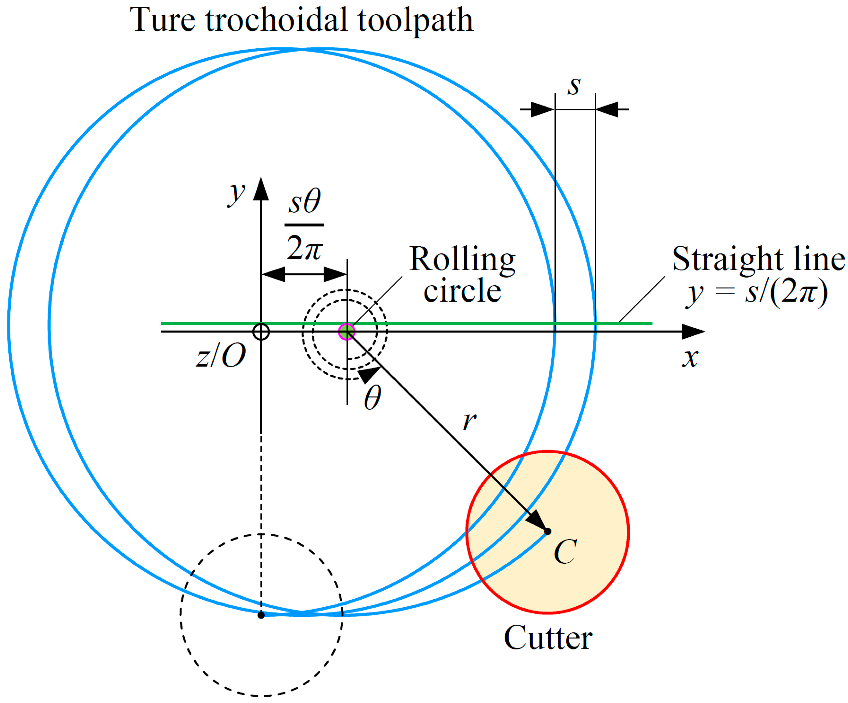
2. Ellipse-Based Trochoidal Toolpath Model

A trochoid is a curve traced by a point fixed to a circle as it rolls along a straight line without slipping [2]. To generate the true trochoidal toolpath, a workpiece coordinate system (WCS) O-xyz is established, as shown in Figure 1. The coordinate system origin O is the rolling circle center at the initial revolution angle θ = 0. The x-axis is parallel to the straight line y = s/(2π) for the case of down milling (where s/(2π) is the radius of the rolling circle, s is the trochoidal step). The z-axis is perpendicular to the upper surface of the workpiece and oriented outwards. The y-axis is determined by using the right-hand rule. Then, the equation of the cutter location C (xC, yC) that corresponds to the fixed point can be expressed as follows:
O C = [ x C ( θ ) y C ( θ ) ] = [ s θ 2 π + r sin θ r cos θ ] ,   for   down-milling ,   and   r > s 2 π
where the parameter θ represents the revolution angle, which rotates counterclockwise from the negative y-axis for down milling. The trochoidal radius r represents the distance from the cutter location to the synchronous rolling circle center.
For the above model, the shape range of the toolpath is determined by the trochoidal radius r and the trochoidal step s (where r represents the revolution range and s represents the feed per revolution). It can be noticed that the revolution ranges in the x-axis and y-axis directions are not independent, they are bound as one control parameter, i.e., the trochoidal radius r. For a fixed-width slot, the trochoidal radius r is uniquely determined once the cutter radius has been selected. However, for a practical slotting process, it is always desirable to have more toolpath control parameters to obtain better machining results, and furthermore, to enhance the advantages of trochoidal milling. Therefore, this paper proposes an ellipse-based trochoidal toolpath model by separating the revolution range from the x-axis and y-axis directions, as shown in Figure 2. The equation of the modified trochoidal toolpath is written as follows:
O C = [ x C ( θ ) y C ( θ ) ] = [ s θ 2 π + b sin θ a cos θ ] ,   for   down-milling ,   and   a b ,   a > s 2 π
where b is the semi-minor axis of the fundamental ellipse and is oriented along the x-axis direction. a is the semi-major axis of the fundamental ellipse and is parallel to the y-axis direction.
The semi-minor axis of the fundamental ellipse is arranged in the x-axis direction, which means that the toolpath is compressed in this direction. The degree of compression can be defined as a ratio ρ = b/a. The advantage of this compression is that the toolpath is shortened, which will be discussed in detail later in Section 4.
During the ellipse-based trochoidal milling process, the cutter rotates around the tool axis at a given spindle speed. The cutting-edge path can be regarded as a circle, whose equation is described as follows:
[ x x C ( θ ) ] 2 + [ y y C ( θ ) ] 2 = R c 2
where Rc is the cutter radius.
The upper and lower boundaries of the slot are given as follows:
{ y = w 2 = a + R c ,   for   the   upper   baundary y = w 2 = ( a + R c ) ,   for   the   lower   baundary
where w is the slot width.

3. Analytical Engagement Angle Model

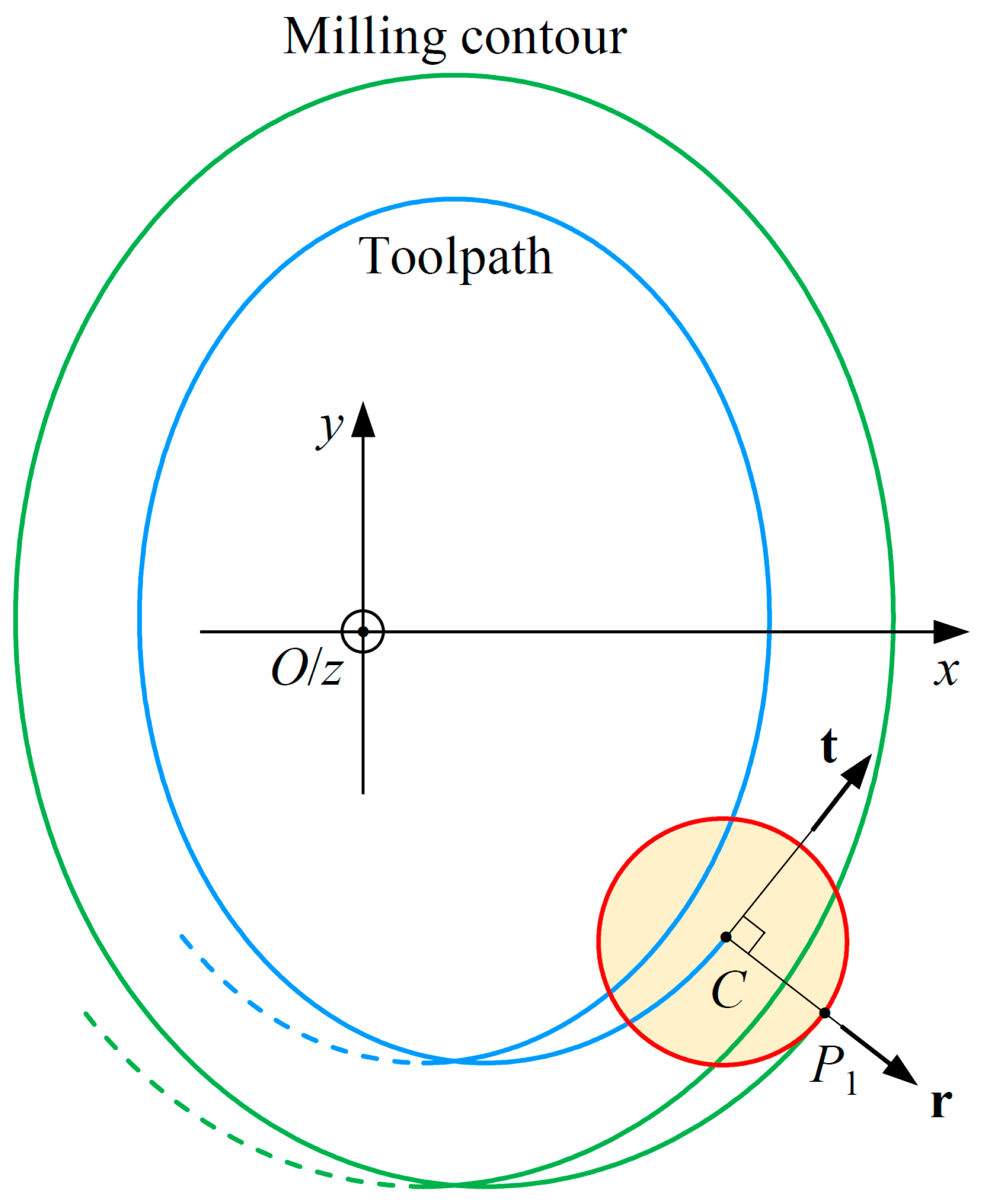
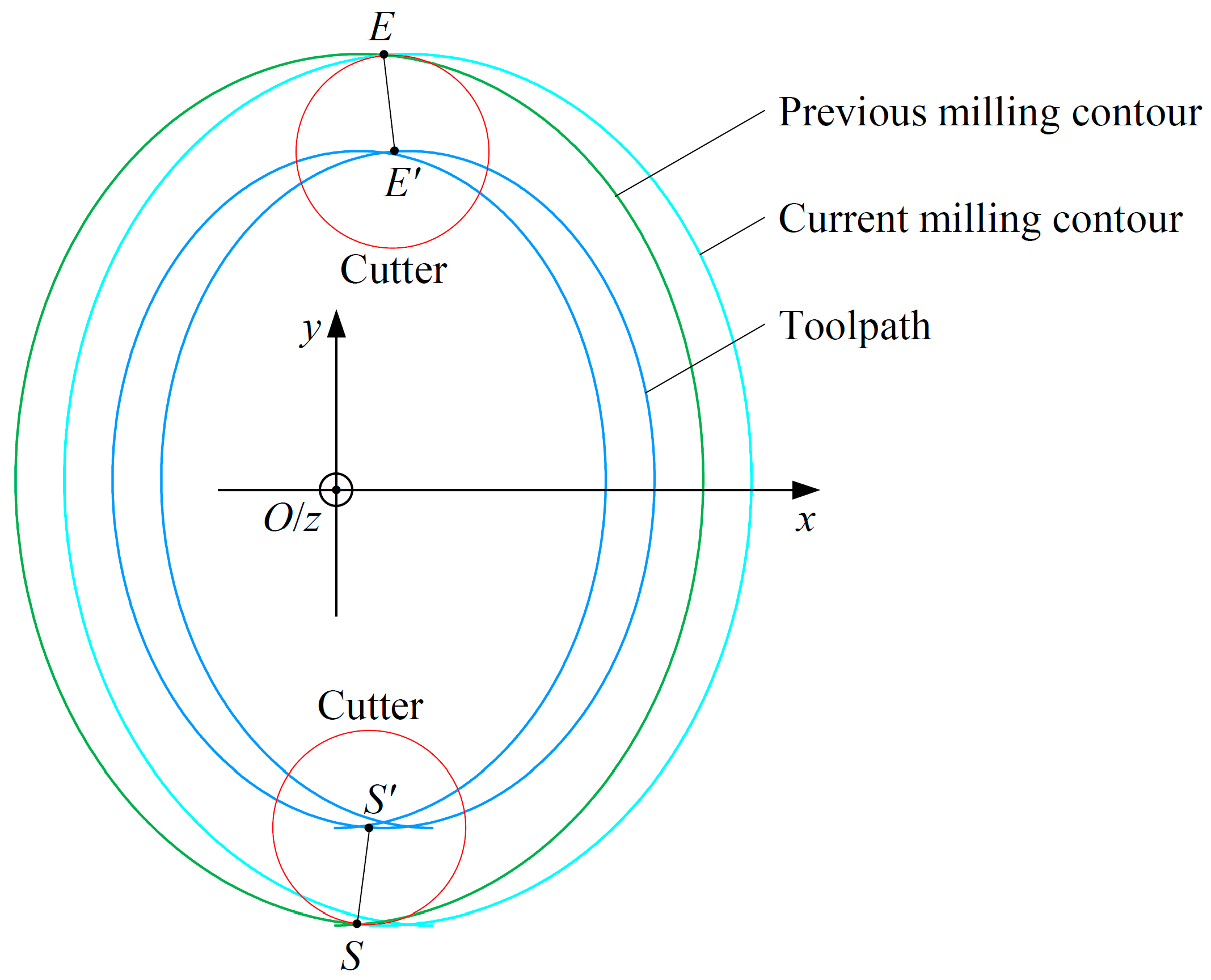
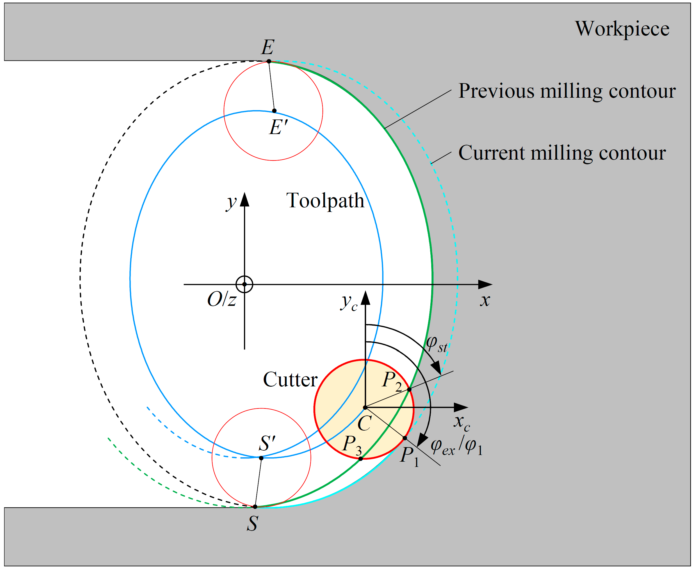
3.1. Effective Cutting Interval of Milling Contour

Figure 3 shows the milling contour corresponding to the ellipse-based trochoidal toolpath. According to Equation (2), the tangential vector t(θ) at the current cutter location C can be expressed as follows:
t ( θ ) = [ t 1 ( θ ) t 2 ( θ ) ] = [ t x ( θ ) t x 2 ( θ ) + t y 2 ( θ ) t y ( θ ) t x 2 ( θ ) + t y 2 ( θ ) ]
where
[ t x ( θ ) t y ( θ ) ] = [ d x C ( θ ) d θ d y C ( θ ) d θ ] = [ s 2 π + b cos θ a sin θ ]
where t1(θ) and t2(θ) are the normalized components of the tangential vector t(θ) in the x-axis and y-axis directions, respectively. tx(θ) and ty(θ) are the partial derivatives of Equation (2).
The radial vector r(θ) at the current cutter location C is orthogonal to the tangential vector t(θ) and can be obtained as follows:
r ( θ ) = [ r 1 ( θ ) r 2 ( θ ) ] = [ t y ( θ ) t x 2 ( θ ) + t y 2 ( θ ) t x ( θ ) t x 2 ( θ ) + t y 2 ( θ ) ]
where r1(θ) and r2(θ) are the normalized components of the radial vector r(θ) in the x-axis and y-axis directions, respectively.
Point P1 is the furthest point from the center of the current fundamental ellipse to the cutting-edge circle and can be calculated as follows:
O P 1 = [ x 1 ( θ ) y 1 ( θ ) ] = O C + R c r ( θ ) = [ x C ( θ ) y C ( θ ) ] + R c [ r 1 ( θ ) r 2 ( θ ) ]
where x1(θ) and y1(θ) are the coordinates of point P1.
Equation (8) is the model of the milling contour left by the cutter, on which P1 represents an arbitrary point. The transition surface of the workpiece is formed by the milling contour. It is part of the milling contour. Therefore, it is necessary to first determine the effective revolution interval within one milling cycle. The cutter-workpiece engagement is also calculated in this revolution interval.
As shown in Figure 4, points S and E represent the initial and final points of the transition surface of the workpiece, respectively. Since the ellipse-based trochoidal toolpath is periodic, the calculation of points S and E are discussed within the first two cycles. Point S is determined within the first milling cycle, i.e., within the revolution interval [0, 2π]. During the first milling cycle, the milling contour itself has one intersection point, whose coordinates can be expressed as follows:
O S = [ x S y S ] = { [ x C ( θ S , 1 ) y C ( θ S , 1 ) ] + R c [ r 1 ( θ S , 1 ) r 2 ( θ S , 1 ) ] [ x C ( θ S , 2 ) y C ( θ S , 2 ) ] + R c [ r 1 ( θ S , 2 ) r 2 ( θ S , 2 ) ] ,   and   θ S , 1 < θ S , 2
where xS and yS are the coordinates of point S. θS,1 and θS,2 denote two revolution angles in the first milling cycle, while satisfying θS,1 < θS,2.
Equation (9) is a transcendental equation and cannot be solved directly by using the analytical method. The two solutions θS,1 and θS,2 are obtained by using the numerical method.
The point on the toolpath corresponding to the revolution angle of θS,2 is defined as S′, whose coordinates can be expressed as follows:
O S = [ x C ( θ S , 2 ) y C ( θ S , 2 ) ]
Point E is determined within the first and second milling cycles, i.e., within the revolution interval [0, 4π]. During the first two milling cycles, the milling contour itself has four intersection points. As shown in Figure 2, one intersection point is close to the upper boundary of the slot; three intersection points are close to the lower boundary of the slot. The intersection point near the upper boundary is the final point E, whose coordinates can be expressed as follows:
O E = [ x E y E ] = { [ x C ( θ E , 1 ) y C ( θ E , 1 ) ] + R c [ r 1 ( θ E , 1 ) r 2 ( θ E , 1 ) ] [ x C ( θ E , 2 ) y C ( θ E , 2 ) ] + R c [ r 1 ( θ E , 2 ) r 2 ( θ E , 2 ) ] ,   and   θ E , 1 < θ E , 2
where xE and yE are the coordinates of point E. θE,1 and θE,2 denote two revolution angles in the first and second milling cycles while satisfying θE,1 < θE,2. More specifically, θE,1 is in the revolution interval [π/2, 3π/2] and θE,2 is in the revolution interval [5π/2, 7π/2].
Equation (11) is also a transcendental equation and must be solved by using the numerical method.
The point on the toolpath corresponding to the revolution angle of θE,2 is defined as E′, whose coordinates can be expressed as follows:
O E = [ x C ( θ E , 2 ) y C ( θ E , 2 ) ]
It should be noticed that points S and E are the boundary points of the newly machined surface, i.e., the new transition surface of the workpiece. Point E is also the cut-out point within a milling cycle. However, point S is not the cut-in point within a milling cycle. As shown in Figure 5, when the cutter center is located at point S′, point S is on the cutting-edge circle. Point P1 coincides with point S. At the same cutter location, there is another intersection point between the cutting-edge circle and the previous milling contour, namely point P2. At this moment, the cutter has cut into the material. The actual cut-in point is point A, where the cutter is tangent to the previous milling contour. The cutter location corresponding to the tangent point A is the intersection point of the toolpath itself within one milling cycle, which is denoted as point A′. Its coordinates can be expressed as follows:
O A = [ x A y A ] = { [ x C ( θ A , 1 ) y C ( θ A , 1 ) ] [ x C ( θ A , 2 ) y C ( θ A , 2 ) ] ,   and   θ A , 1 < θ A , 2
where xA and yA are the coordinates of point A′. θA,1 and θA,2 denote two revolution angles in the first milling cycle while satisfying 0 < θA,1 < θA,2 < π/2.
Then, for each milling cycle, the effective revolution interval corresponding to the actual cutting process can be expressed as follows:
[ θ A , 2 + 2 π ( m 1 ) ] θ [ θ E , 2 + 2 π ( m 1 ) ]
where
m = int ( θ 2 π )
where m is the number of complete milling cycles. Notably, int is the function that rounds positive numbers towards zero (e.g., int(1.25) = 1, int(2.75) = 2).

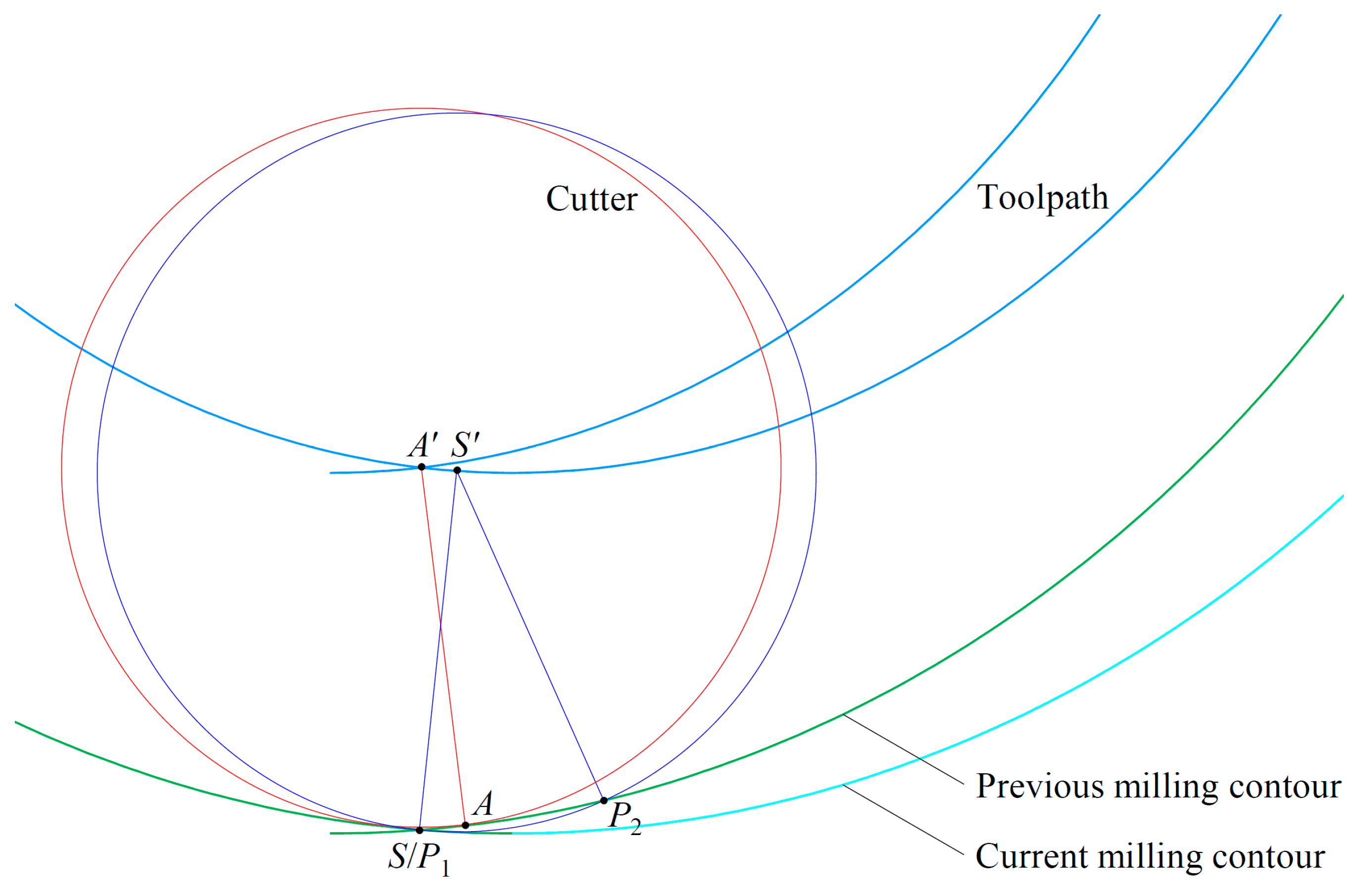
3.2. Calculation of Cutter-Workpiece Engagement Angle

To predict the cutting forces, the cutter-workpiece engagement angle which changes continuously in ellipse-based trochoidal milling must be evaluated. A cutter coordinate system (CCS) C-xcyczc is established. The origin of the CCS is the current cutter location. The xc-axis, yc-axis, and zc-axis are parallel to the x-axis, y-axis, and z-axis of the WCS, respectively.
For the segment SE′ of the toolpath, as shown in Figure 6, the cutter-workpiece engagement angle is calculated between the current and previous milling contours. Point P1 is the contact point between the current milling contour and the cutter. Points P2 and P3 are two intersection points between the previous milling contour and the cutting-edge circle. For the down-milling mode, point P2 is the effective cutting point, which is involved in determining the engagement angle, while point P3 is located in the non-cutting segment. The angle wrapped by the clockwise rotation from point P2 to point P1 is the cutter-workpiece engagement angle. All cutting edges within this interval are involved in cutting.
The start angle φst is measured between the vector C P 2 and the positive yc-axis. The exit angle φex is measured between the vector C P 1 and the positive yc-axis. The cutter-workpiece engagement angle φen is obtained to be φen = φex − φst. It can be seen that the start angle φst, the exit angle φex, and the engagement angle φen can be obtained by determining the coordinates of points P2 and P1. The coordinates of point P1 are obtained by Equation (8). The coordinates of point P2 can be found by solving the following equations:
{ ( x 2 x C ) 2 + ( y 2 y C ) 2 = R c 2 ( x 3 x C ) 2 + ( y 3 y C ) 2 = R c 2 [ x 2 y 2 ] = [ x C ( θ p r e , 2 ) y C ( θ p r e , 2 ) ] + R c [ r 1 ( θ p r e , 2 ) r 2 ( θ p r e , 2 ) ] [ x 3 y 3 ] = [ x C ( θ p r e , 3 ) y C ( θ p r e , 3 ) ] + R c [ r 1 ( θ p r e , 3 ) r 2 ( θ p r e , 3 ) ]
where x2 and y2 are the coordinates of point P2. x3 and y3 are the coordinates of point P3. θpre,2 and θpre,3 are the revolution angles corresponding to points P2 and P3 within the previous milling contour, respectively, while satisfying θpre,2 > θpre,3.
The system of Equation (16) is solved by the numerical method in the revolution interval [0, 2π].
Then, the start angle φst can be calculated as follows:
φ s t = { arccos j C P 2 | j | | C P 2 | = arccos y 2 ( θ p r e , 2 ) y C ( θ ) R c ,   when   i C P 2 < 0   and   j C P 2 > 0 arccos j C P 2 | j | | C P 2 | = arccos y 2 ( θ p r e , 2 ) y C ( θ ) R c ,   when   i C P 2 0 2 π arccos j C P 2 | j | | C P 2 | = 2 π arccos y 2 ( θ p r e , 2 ) y C ( θ ) R c ,   when   i C P 2 < 0   and   j C P 2 < 0
where i is the unit vector of the xc-axis. j is the unit vector of the yc-axis.
Similarly, the exit angle φex can be calculated as follows:
φ e x = φ 1 = { arccos j C P 1 | j | | C P 1 | = arccos y 1 ( θ ) y C ( θ ) R c ,   when   i C P 1 < 0   and   j C P 1 > 0 arccos j C P 1 | j | | C P 1 | = arccos y 1 ( θ ) y C ( θ ) R c ,   when   i C P 1 0 2 π arccos j C P 1 | j | | C P 1 | = 2 π arccos y 1 ( θ ) y C ( θ ) R c ,   when   i C P 1 < 0   and   j C P 1 < 0
For segment AS′ of the toolpath, as shown in Figure 7, the two intersection points of the cutting-edge circle and the previous milling contour are involved in the engagement angle calculation. Point P2 is used to calculate the start angle φst by means of Equation (17). Point P3 is used to calculate the exit angle φex, which can be expressed as follows:
φ e x = { arccos j C P 3 | j | | C P 3 | = arccos y 3 ( θ p r e , 3 ) y C ( θ ) R c ,   when   i C P 3 0 2 π arccos j C P 3 | j | | C P 3 | = 2 π arccos y 3 ( θ p r e , 3 ) y C ( θ ) R c ,   when   i C P 3 < 0
Point P1 is used to calculate the angle φ1, which can be expressed as follows:
φ 1 = { arccos j C P 1 | j | | C P 1 | = arccos y 1 ( θ ) y C ( θ ) R c ,   when   i C P 1 0 2 π arccos j C P 1 | j | | C P 1 | = 2 π arccos y 1 ( θ ) y C ( θ ) R c ,   when   i C P 1 < 0

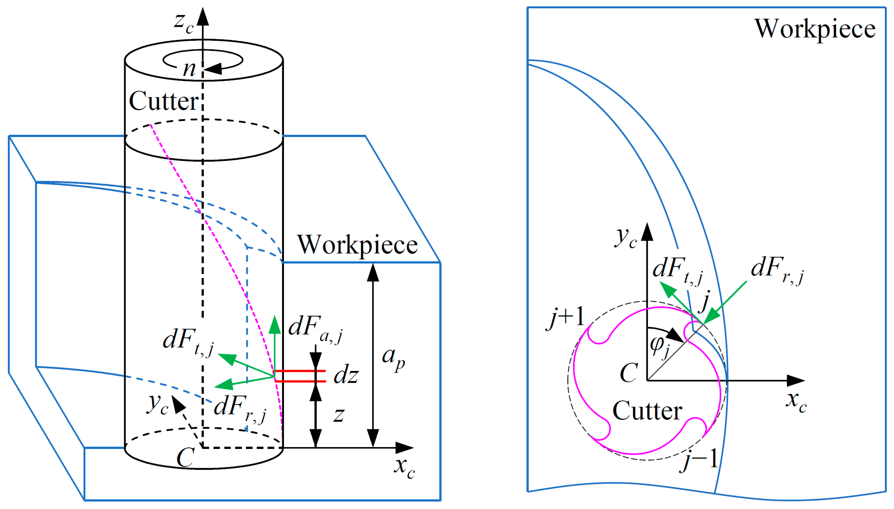
4. Mechanistic Cutting-Force Model

The method for calculating the cutting force in ellipse-based trochoidal milling is based on the mechanistic cutting-force model [37]. As shown in Figure 8, the cutter is divided into a finite number of small differential elements along the tool axis. For each cutting element, three orthogonal cutting-force components acting on the jth flute can be expressed as follows:
[ d F t , j ( φ j ( z ) ) d F r , j ( φ j ( z ) ) d F a , j ( φ j ( z ) ) ] = [ K t e d z + K t c h j ( φ j ( z ) ) d z K r e d z + K r c h j ( φ j ( z ) ) d z K a e d z + K a c h j ( φ j ( z ) ) d z ]
where Kte, Kre, and Kae are the edge force coefficients in tangential, radial, and axial directions, respectively. Ktc, Krc, and Kac are the cutting-force coefficients in tangential, radial, and axial directions, respectively. dz is the axial differential height. hj(φj(z)) is the instantaneous undeformed chip thickness. φj(z) is the radial immersion angle of the cutting edge j, and it can be expressed as follows:
φ j ( z ) = φ + ( j 1 ) φ p ψ ( z ) = 2 π n 60 t + ( j 1 ) 2 π N 2 z tan β D
where φ is the rotation angle of the cutting edge. φp is the pitch angle of the cutter. ψ(z) is the radial lag angle caused by the local helix angle. n is the spindle speed. t is the time parameter. N is the number of cutting flutes. β is the constant helix angle of the cutter. D is the cutter diameter.
The feed direction can change the distribution of the cutting force in the x-axis and y-axis directions in the WCS. The radius of the curvature of the toolpath can lead to different feed rates at each point of the cutting-edge circle [38,39], as shown in Figure 9. Therefore, the instantaneous undeformed chip thickness is determined as follows:
h j ( φ j ( z ) ) = f t ( φ j ( z ) ) sin ( φ j ( z ) + π φ 1 ) ,   and   φ s t φ j ( z ) φ e x
where
f t ( φ j ( z ) ) = f t [ R p + R c cos ( φ 1 φ j ( z ) ) ] R p
where ft(φj(z)) is the feed rate at each point of the cutting-edge circle. φ1 is measured clockwise from the positive yc-axis to the vector C P 1 . πφ1 denotes the angular change in the feed direction. ft is the normal feed per tooth at the cutter center. Rp is the radius of curvature of the toolpath and can be expressed as follows:
R p = [ 1 + ( d y C ( θ ) d x C ( θ ) ) 2 ] 3 2 | d 2 y C ( θ ) d x C 2 ( θ ) | = [ 1 + ( a sin θ s 2 π + b cos θ ) 2 ] 3 2 | ( s 2 π + b cos θ ) 3 | | s a cos θ 2 π + a b |
Once three orthogonal cutting-force components are obtained, they can be mapped into a Cartesian coordinate system. The tangential, radial, and axial forces are resolved in the feed (x), normal (y), and axial (z) directions using a transformation as follows:
[ d F x , j ( φ j ( z ) ) d F y , j ( φ j ( z ) ) d F z , j ( φ j ( z ) ) ] = [ cos φ j ( z ) sin φ j ( z ) 0 sin φ j ( z ) cos φ j ( z ) 0 0 0 1 ] [ d F t , j ( φ j ( z ) ) d F r , j ( φ j ( z ) ) d F a , j ( φ j ( z ) ) ]
Then, the total cutting-force components for the rotational position φ can be evaluated by summing up the forces acting on all edges along the axial depth of the cut:
[ F x F y F z ] = [ j = 1 N z = 0 z = a p d F x , j ( φ j ( z ) ) j = 1 N z = 0 z = a p d F y , j ( φ j ( z ) ) j = 1 N z = 0 z = a p d F z , j ( φ j ( z ) ) ]
where ap is the axial depth of the cut.
The resultant cutting force acting on the flat-end cutter is as follows:
F = F x 2 + F y 2 + F z 2

5. Results and Validation

In this section, the ellipse-based trochoidal toolpaths are first generated. Then, the cutter-workpiece engagement angles are calculated and analyzed. Thereafter, the cutting-force coefficients are identified, and the cutting forces are predicted. At last, a series of milling tests are implemented to verify the proposed method.
The basic information about the cutter and the workpiece involved in the verification experiments is described here. The cutter is a TiAlN-coated solid carbide flat-end mill. The detailed specifications of the cutter are presented in Table 1. The workpiece is a straight slot made of titanium alloy Ti-6Al-4V. The geometrical parameters, physical parameters, and chemical compositions of the workpiece are listed in Table 2.

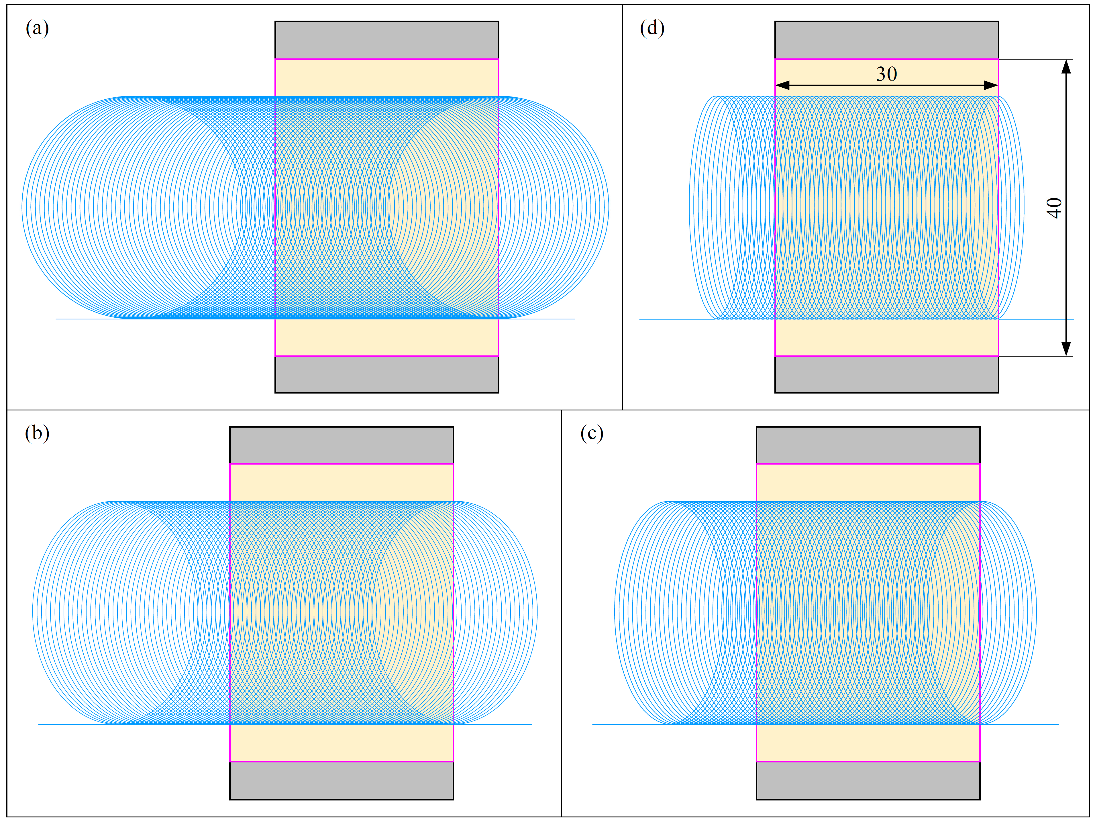
5.1. Ellipse-Based Trochoidal Toolpath

For the slots with given dimensions, the ellipse-based trochoidal toolpaths can be generated for different toolpath parameters by applying Equation (2). Figure 10 shows the toolpaths for four different compression ratios of 100%, 75%, 50%, and 25%. The cutter radius is 5 mm. The trochoidal step is 0.6 mm. Then, the semi-major axis of the fundamental ellipse can be determined by Equation (4) to be 15 mm. The four corresponding semi-minor axes of the fundamental ellipse are 15, 11.25, 7.5, and 3.75 mm. A compression ratio of 100% signifies a non-compressed state. It means that the toolpath is a true trochoidal toolpath. Both the engage and retract distances of the four trochoidal toolpaths are set to 10 mm. The path lengths for the four different trochoidal toolpaths during a single milling cycle are 94.25, 82.89, 72.67, and 64.34 mm, respectively. The entire number of milling cycles for the 4 different trochoidal toolpaths are 83, 77, 71, and 64, respectively. Then, the total length for the four trochoidal toolpaths can be calculated to be 7842.8, 6402.5, 5179.6, and 4137.8 mm, respectively. Compared with the case of a compression ratio of 100%, the total toolpath lengths for the compression ratios of 75%, 50%, and 25% are reduced by 18.4%, 34.0%, and 47.2%, respectively. It can be seen that the lower the compression ratio, the smaller the number of milling cycles, the shorter the total toolpath length, and the higher the machining efficiency. In other words, the roughing efficiency of the trochoidal milling strategy can be further improved by compressing the toolpath in step direction.

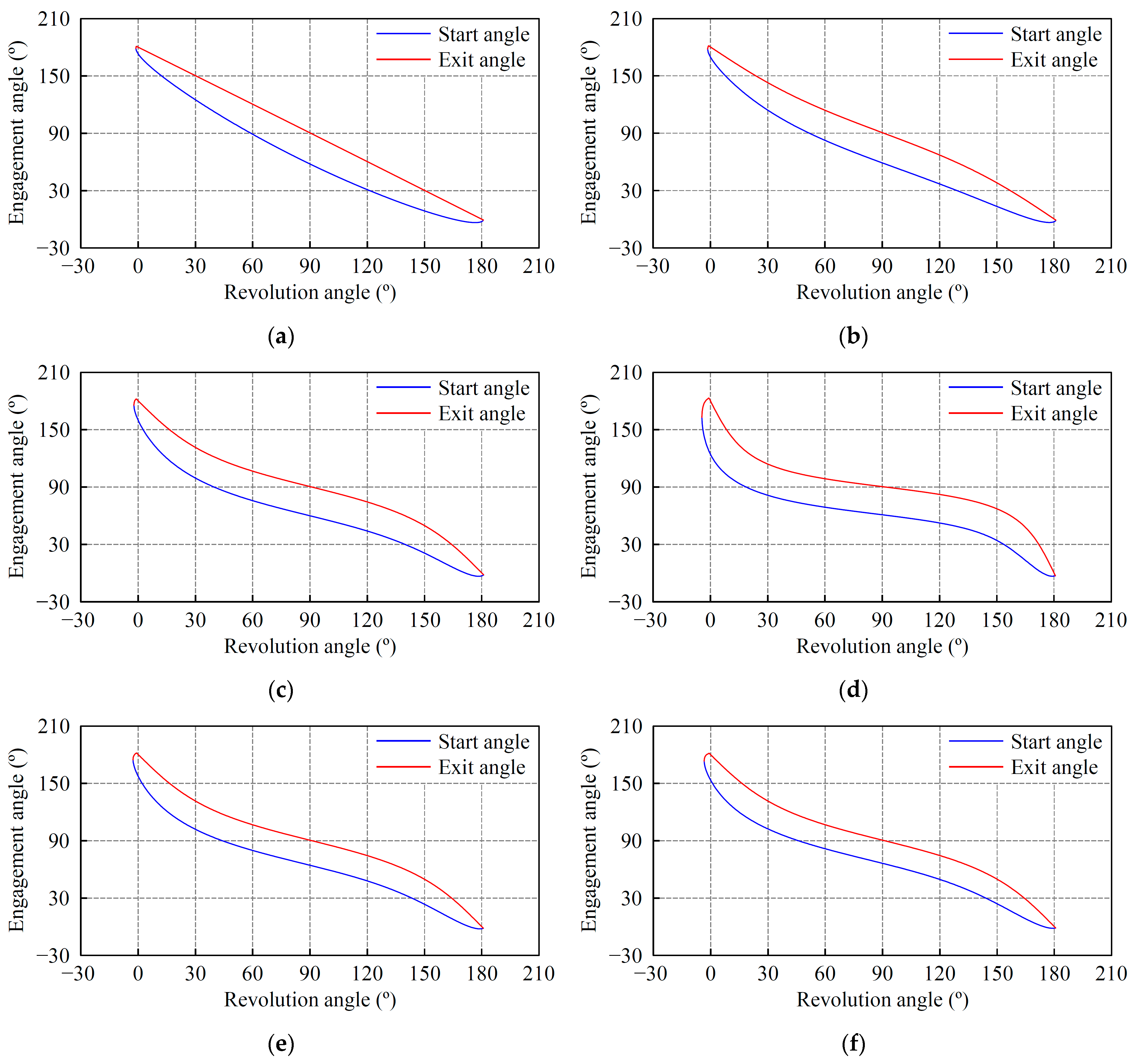
5.2. Cutter-Workpiece Engagement Angle

The relationship between engagement angle and toolpath parameters is investigated here. The cutter-workpiece engagement angles with different toolpath parameters are calculated by using the proposed method in Section 3. The toolpath parameters are listed in Table 3. The corresponding start and exit angles are plotted in Figure 11a–f.
Figure 11a–d show that as the compression ratio decreases, the start and exit angles gradually increase in the initial stage, gradually decrease in the final stage, and change less in the middle stage. Figure 12 shows the variation of the engagement angle with the revolution angle for different compression ratios. It can be found that as the compression ratio decreases from 100% to 50%, the engagement angle becomes more balanced. This is beneficial for balancing the cutting load. As the compression ratio decreases from 50% to 25%, the engagement angle increases significantly in both the initial and final stages, especially in the initial stage. While in the middle stage, it decreases just slightly. This leads to the fact that the trochoidal toolpath cannot be compressed infinitely in the step direction in order to improve the machining efficiency. For the trochoidal toolpath in this slotting example, a compression ratio of 50% is optimal.
Figure 13 shows the variation of the engagement angle with the revolution angle for different cutter radii. It can be found that when the compression ratio is set to 50%, the engagement angle tends to sink slightly in the middle and final stages as the cutter radius increases. While the overall variation is not significant. More specifically, as the cutter radius becomes larger, the exit angle remains essentially unchanged, while the start angle sinks slightly in the middle and final stages of the effective revolution interval. In summary, the effect of the cutter radius on the engagement angle is not significant.

5.3. Cutting-Force Analysis and Experimental Validation

The cutting-force coefficients are identified by a series of milling tests on a VMC-850 machining center. The experimental setup is shown in Figure 14. The cutting forces are collected by a three-dimensional dynamometer Kistler 9257B. The workpiece is mounted on the dynamometer through a vise fixture. The milling tests are conducted in the type of down-milling mode and dry cutting operation. The machining parameters are listed in Table 4. According to the identification approach proposed by Budak [40], the tangential, radial, and axial cutting and edge coefficients for the selected combination of cutter and workpiece materials are obtained. The cutting-force coefficients Ktc, Krc, and Kac are 2082.5, 625.1, and 947.8 N/mm2 as calculated by means of the shearing action in the tangential, radial, and axial directions, respectively. The edge force coefficients Kte, Kre, and Kae are 11.0, 24.4, and 2.0 N/mm, respectively.
Figure 15 shows the ellipse-based trochoidal milling of straight slots. The cutting forces are measured by the dynamometer Kistler 9257B. For ellipse-based trochoidal milling, the cutting force in one cycle varies with the cutter location. Therefore, it is necessary to determine the cutting force at different revolution angles. According to the mechanistic cutting-force model presented in Section 4, the cutting force in ellipse-based trochoidal milling is predicted, as shown in Figure 16. The spindle speed is 2000 r/min. The feed rate is 480 mm/min. The semi-major and semi-minor axes of the fundamental ellipse are 15 and 11.25 mm. Therefore, the compression ratio is 75%. The cutter radius is 5 mm. The trochoidal step is 0.6 mm. It can be found that the predicted and measured cutting forces have the same profile in x-, y-, and z-axes, respectively, and the cutting-force amplitudes correspond well.
Figure 17 shows the predicted total cutting forces involved in the trochoidal milling with different toolpath parameters. Comparing the total cutting forces with the engagement angles, it can be seen that the profile of the total cutting force corresponds to that of the engagement angle. As the compression ratio decreases, the trend of the total cutting force is the same as the trend of the engagement angle. Especially when the compression ratio decreases from 50% to 25%, the total cutting force increases sharply in the initial stage. This will severely damage the cutter as well as the machine tool and should be avoided.

6. Conclusions

This paper investigates the analytical model of the cutter-workpiece engagement angle and the prediction method of the cutting forces in the ellipse-based trochoidal milling process. Our conclusions are summarized as follows:
(1)
An ellipse-based trochoidal toolpath model is developed by extending the true trochoidal toolpath model with a control parameter, namely the compression ratio in the trochoidal step direction.
(2)
The analytical milling contour equation corresponding to the ellipse-based trochoidal toolpath is presented and the effective revolution interval within the actual cutting process is determined.
(3)
An analytical calculation method for the start and exit angles for the ellipse-based trochoidal milling process is proposed.
(4)
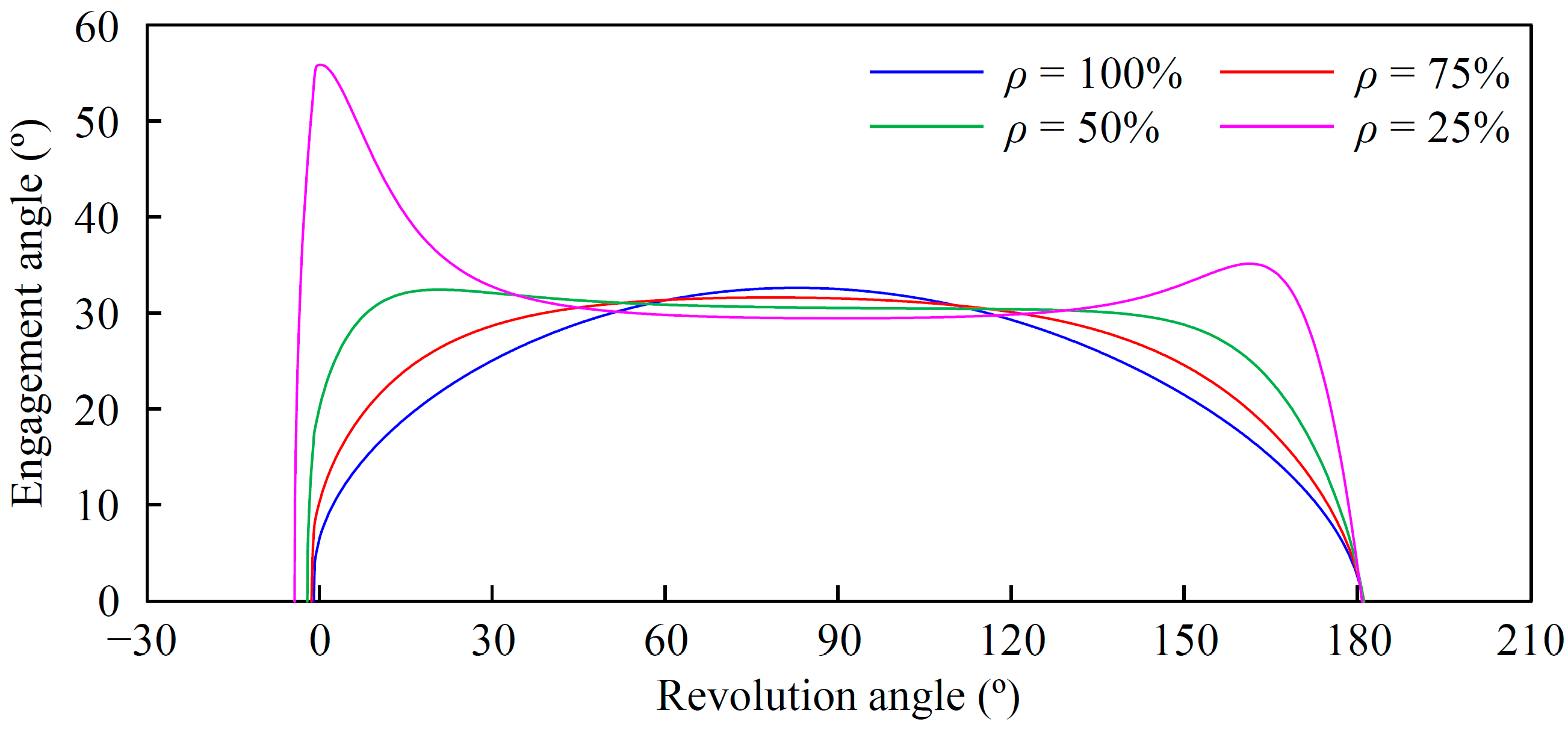
The compression ratio has significant effects on the trochoidal toolpath length and the cutter-workpiece engagement angle. The smaller the compression ratio, the shorter the overall trochoidal toolpath length, and the higher the material removal rate. As the compression ratio decreases, the engagement angle first becomes more balanced within the effective milling interval and then increases steeply in the initial and final segments. In this research, a compression ratio of 50% is optimal.
(5)
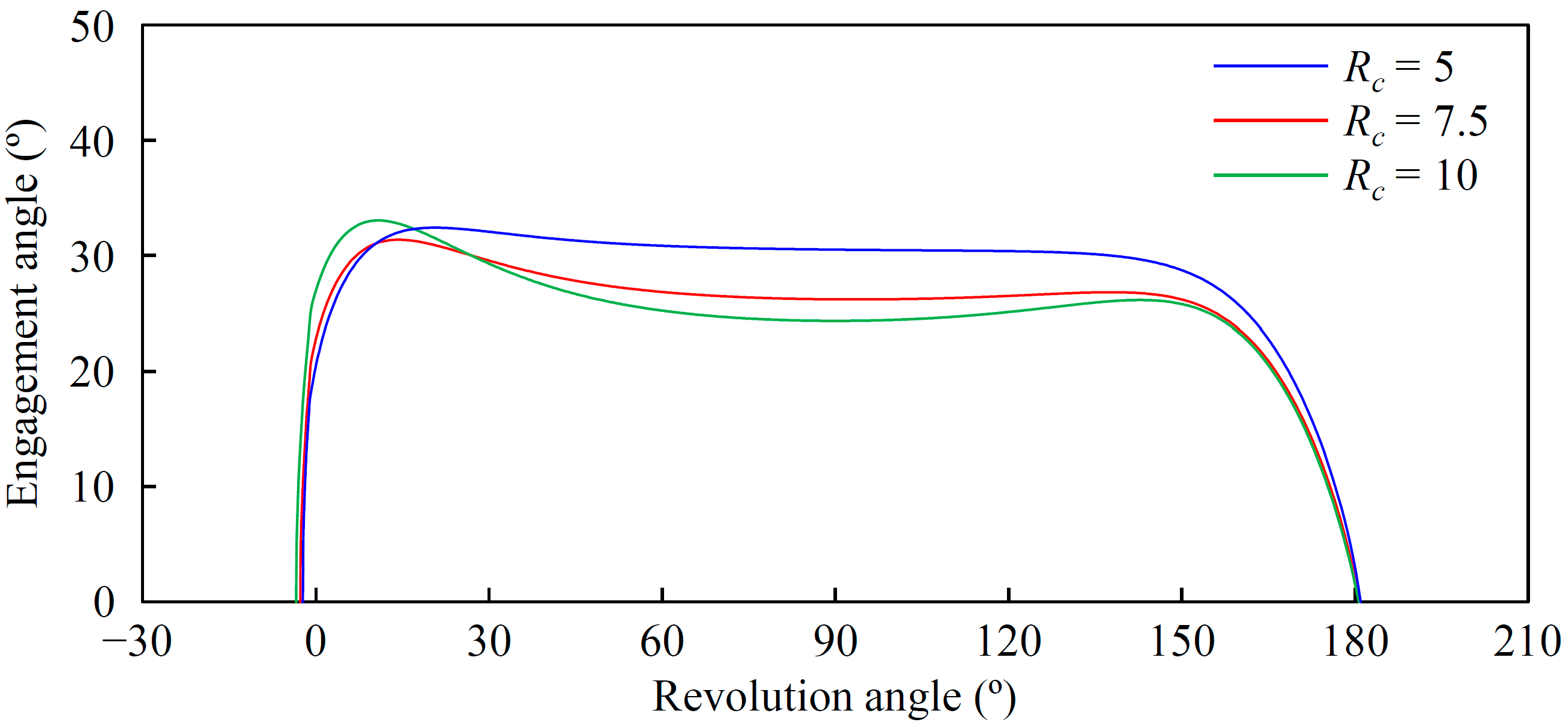
The effect of the cutter radius on the cutter-workpiece engagement angle is minimal. A larger cutter radius does not cause an obvious change in the engagement angle. However, a larger cutter radius results in a smaller semi-major axis of the fundamental ellipse, which helps to shorten the total trochoidal toolpath length.
(6)
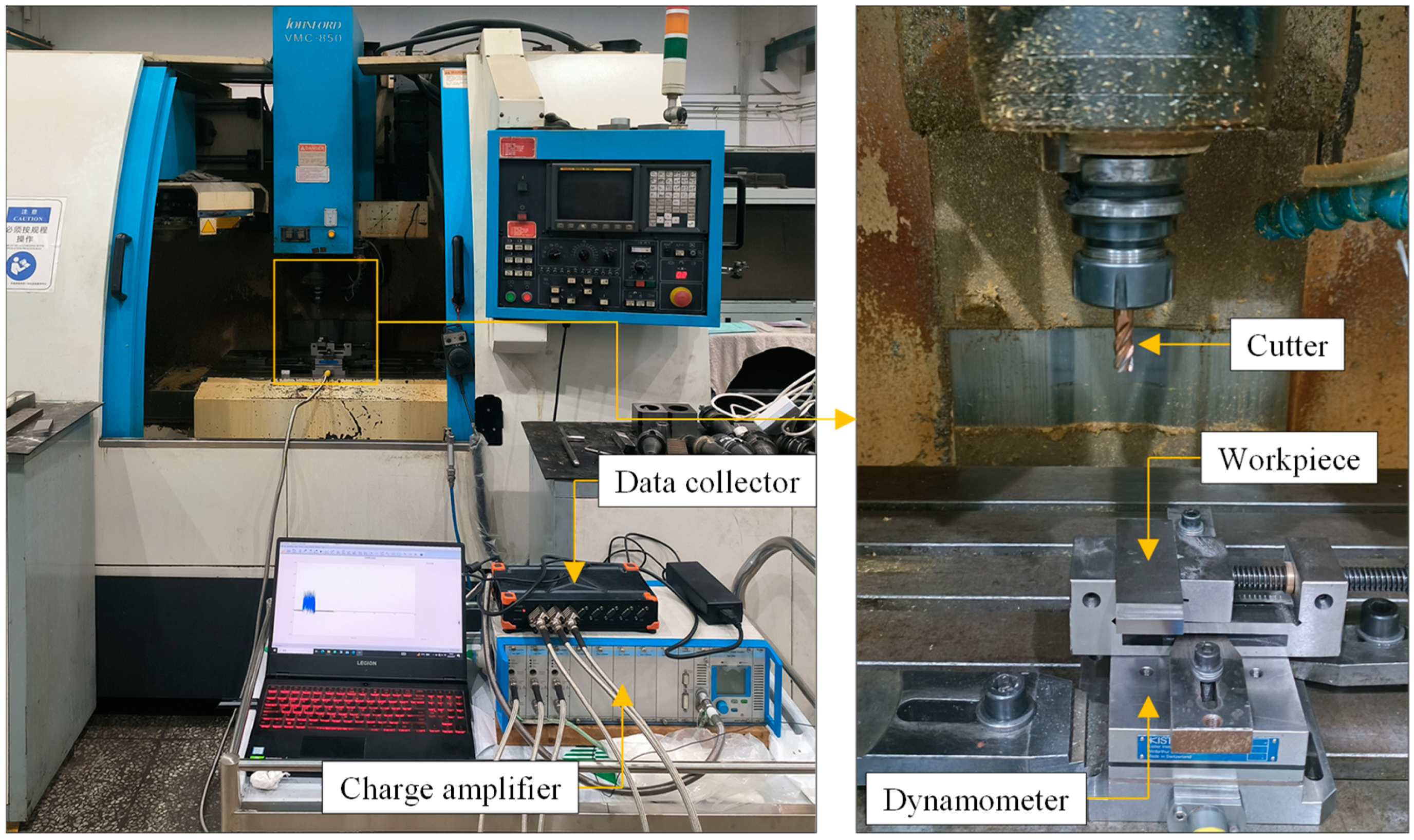
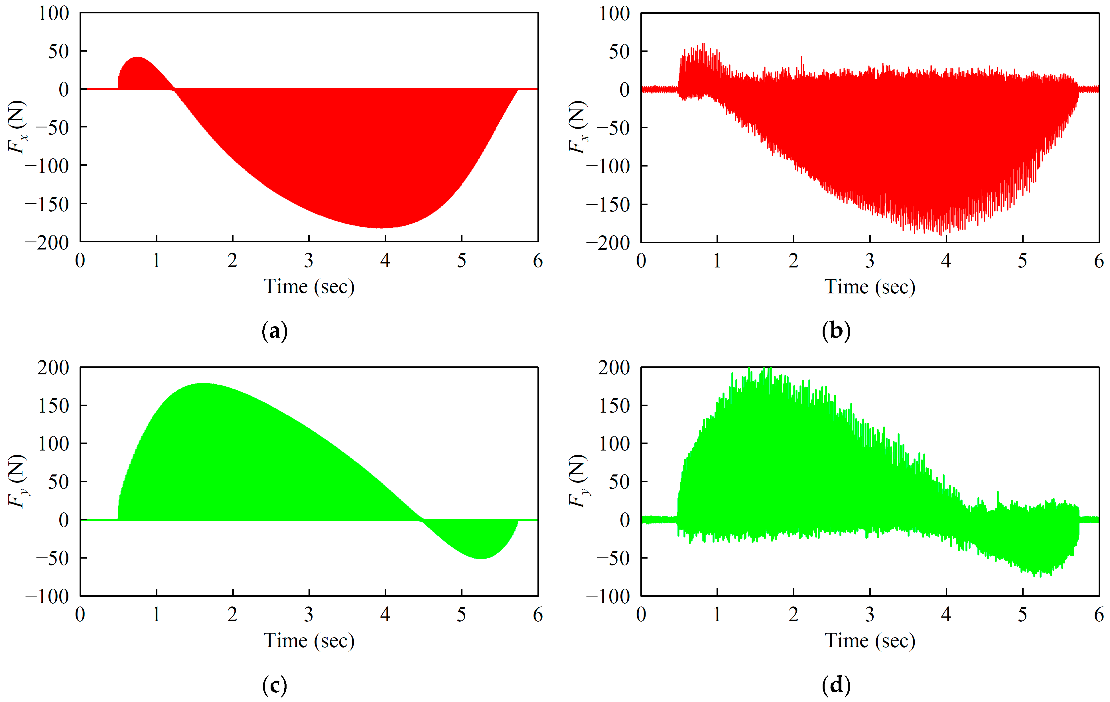
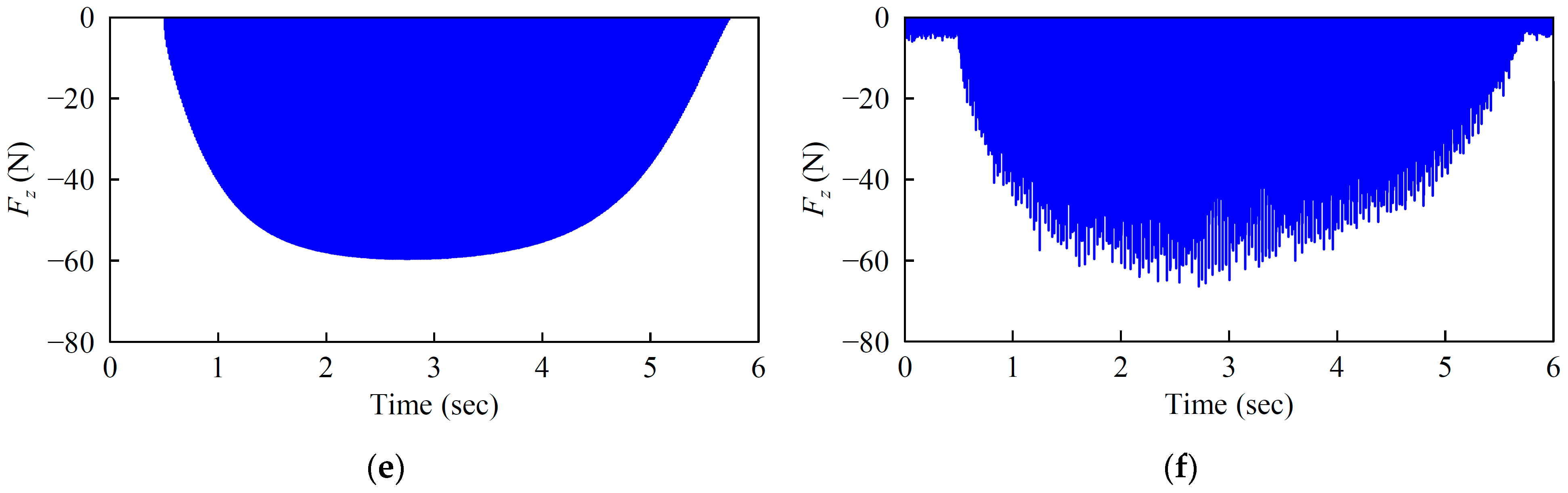
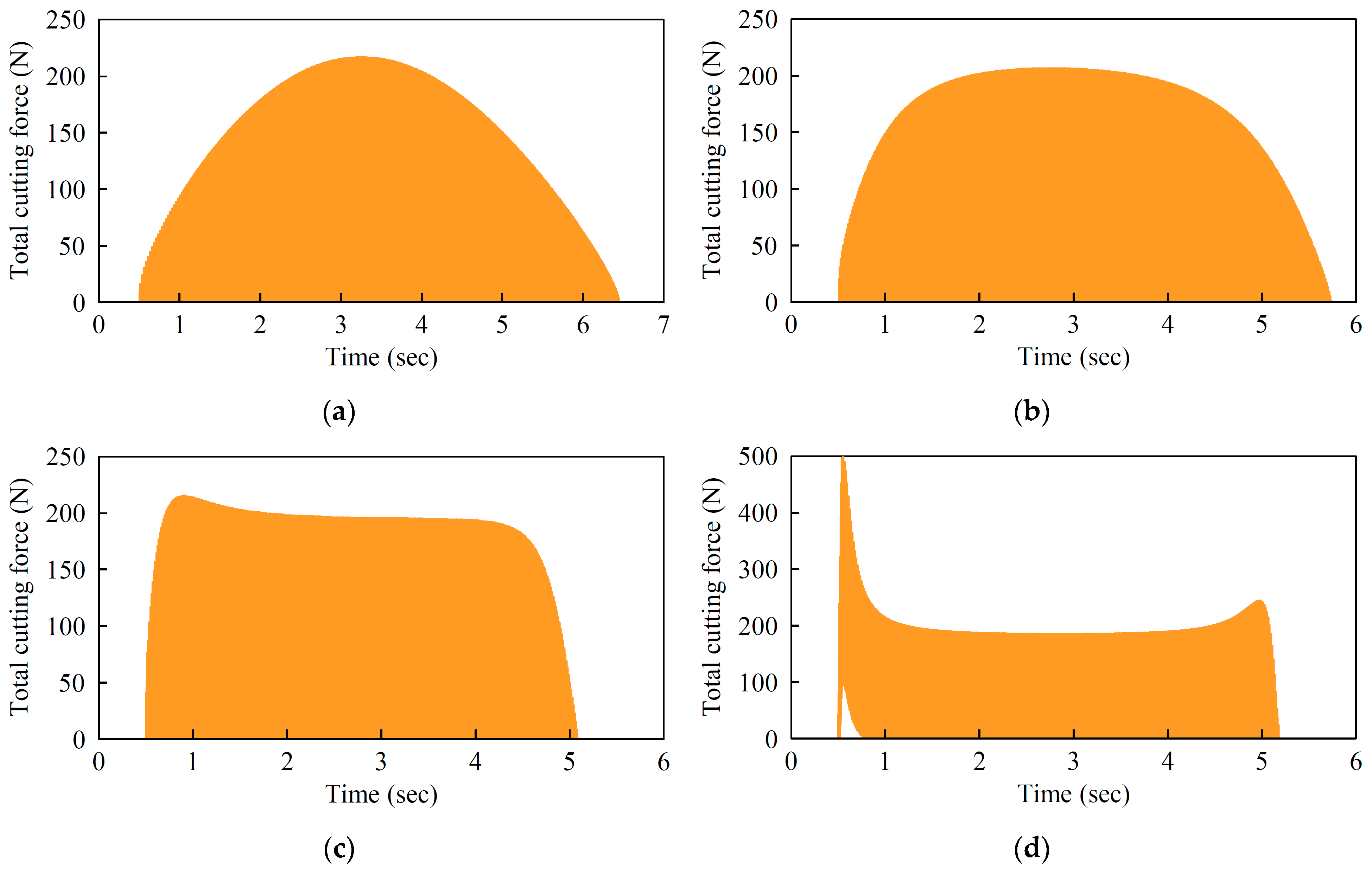
The cutting-force coefficients for the milling of titanium alloy Ti-6Al-4V with a flat-end cutter are identified. Several ellipse-based trochoidal milling experiments with different toolpath parameters are conducted to verify the accuracy and reliability of the proposed method. It can be found that the predicted results agree well with the experimental data.
(7)
The trends in cutting force are consistent with the trends in cutter-workpiece engagement angle for different trochoidal toolpath parameters.

Author Contributions

Conceptualization, X.Z. and D.Z.; methodology, X.Z., J.Z. and Q.Q.; software, X.Z. and J.Z.; validation, Q.Q. and J.Z.; formal analysis, C.Z. and D.Z.; data curation, X.Z. and Q.Q.; writing—original draft preparation, X.Z.; writing—review and editing, C.Z. and J.Z.; funding acquisition, X.Z., J.Z. and C.Z. All authors have read and agreed to the published version of the manuscript.

Funding

This research was supported by the National Key Research and Development Program of China, grant number 2020YFF0304905; the National Natural Science Foundation of China, grant number 52075451; the Science Center for Gas Turbine Project, grant number P2022-B-IV-012-001; and the Aeronautical Science Foundation of China, grant number 2019ZE053008.

Institutional Review Board Statement

Not applicable.

Informed Consent Statement

Not applicable.

Data Availability Statement

Not applicable.

Conflicts of Interest

The authors declare no conflict of interest.

References

  1. Rauch, M.; Duc, E.; Hascoet, J.Y. Improving trochoidal tool paths generation and implementation using process constraints modelling. Int. J. Mach. Tools Manuf. 2009, 49, 375–383. [Google Scholar] [CrossRef]
  2. Luo, M.; Han, C.; Hafeez, H.M. Four-axis trochoidal toolpath planning for rough milling of aero-engine blisks. Chin. J. Aeronaut. 2019, 32, 2009–2016. [Google Scholar] [CrossRef]
  3. Ren, J.X.; Yao, C.F.; Zhang, D.H.; Xue, Y.L.; Liang, Y.S. Research on tool path planning method of four-axis high-efficiency slot plunge milling for open blisk. Int. J. Adv. Manuf. Technol. 2009, 45, 101–109. [Google Scholar] [CrossRef]
  4. Sun, C.; Wang, Y.; Huang, N. A new plunge milling tool path generation method for radial depth control using medial axis transform. Int. J. Adv. Manuf. Technol. 2015, 76, 1575–1582. [Google Scholar] [CrossRef]
  5. Xu, J.; Sun, Y.; Zhang, X. A mapping-based spiral cutting strategy for pocket machining. Int. J. Adv. Manuf. Technol. 2013, 67, 2489–2500. [Google Scholar] [CrossRef]
  6. Urbikain Pelayo, G.; Olvera-Trejo, D.; Luo, M.; Tang, K.; López de Lacalle, L.N.; Elías-Zuñiga, A. A model-based sustainable productivity concept for the best decision-making in rough milling operations. Measurement 2021, 186, 110120. [Google Scholar] [CrossRef]
  7. Xu, K.; Wu, B.; Li, Z.; Tang, K. Time-Efficient Trochoidal Tool Path Generation for Milling Arbitrary Curved Slots. J. Manuf. Sci. Eng. 2019, 141, 031008. [Google Scholar] [CrossRef]
  8. Deng, Q.; Mo, R.; Chen, Z.C.; Chang, Z. An Analytical Approach to Cutter Edge Temperature Prediction in Milling and Its Application to Trochoidal Milling. Appl. Sci. 2020, 10, 1746. [Google Scholar] [CrossRef]
  9. Elber, G.; Cohen, E.; Drake, S. MATHSM: Medial axis transform toward high speed machining of pockets. Comput. Aided Des. 2005, 37, 241–250. [Google Scholar] [CrossRef]
  10. Otkur, M.; Lazoglu, I. Trochoidal milling. Int. J. Mach. Tools Manuf. 2007, 47, 1324–1332. [Google Scholar] [CrossRef]
  11. Ferreira, J.C.; Ochoa, D.M. A method for generating trochoidal tool paths for 2½D pocket milling process planning with multiple tools. Proc. Inst. Mech. Eng. B J. Eng. Manuf. 2013, 227, 1287–1298. [Google Scholar] [CrossRef]
  12. Wang, Q.H.; Wang, S.; Jiang, F.; Li, J.R. Adaptive trochoidal toolpath for complex pockets machining. Int. J. Prod. Res. 2016, 54, 5976–5989. [Google Scholar] [CrossRef]
  13. Deng, Q.; Mo, R.; Chen, Z.C.; Chang, Z. A new approach to generating trochoidal tool paths for effective corner machining. Int. J. Adv. Manuf. Technol. 2018, 95, 3001–3012. [Google Scholar] [CrossRef]
  14. Huang, X.; Wu, S.; Liang, L.; Li, X.; Huang, N. Efficient trochoidal milling based on medial axis transformation and inscribed ellipse. Int. J. Adv. Manuf. Technol. 2020, 111, 1069–1076. [Google Scholar] [CrossRef]
  15. Jacso, A.; Sikarwar, B.S.; Phanden, R.K.; Singh, R.K.; Ramkumar, J.; Sahu, G.N. Optimisation of tool path shape in trochoidal milling using B-spline curves. Int. J. Adv. Manuf. Technol. 2022, 121, 3801–3816. [Google Scholar] [CrossRef]
  16. Chang, C.H.; Huang, M.; Yau, H.T. A double-NURBS approach to the generation of trochoidal tool path. Int. J. Adv. Manuf. Technol. 2023, 125, 1757–1776. [Google Scholar] [CrossRef]
  17. Li, Z.; Xu, K.; Tang, K. A new trochoidal pattern for slotting operation. Int. J. Adv. Manuf. Technol. 2019, 102, 1153–1163. [Google Scholar] [CrossRef]
  18. Li, Z.; Chen, L.; Xu, K.; Gao, Y.; Tang, K. Five-axis Trochoidal Flank Milling of Deep 3D Cavities. Comput. Aided Des. 2020, 119, 102775. [Google Scholar] [CrossRef]
  19. Li, Z.; Hu, P.; Xie, F.; Tang, K. A variable-depth multi-layer five-axis trochoidal milling method for machining deep freeform 3D slots. Robot. Comput. Integr. Manuf. 2021, 68, 102093. [Google Scholar] [CrossRef]
  20. Wu, S.; Ma, W.; Li, B.; Wang, C. Trochoidal machining for the high-speed milling of pockets. J. Mater. Process. Technol. 2016, 233, 29–43. [Google Scholar]
  21. Liu, D.; Zhang, Y.; Luo, M.; Zhang, D. Investigation of tool wear and chip morphology in dry trochoidal milling of titanium alloy Ti–6Al–4V. Materials 2019, 12, 1937. [Google Scholar] [CrossRef]
  22. Karkalos, N.E.; Karmiris-Obratański, P.; Kurpiel, S.; Zagórski, K.; Markopoulos, A.P. Investigation on the Surface Quality Obtained during Trochoidal Milling of 6082 Aluminum Alloy. Machines 2021, 9, 75. [Google Scholar] [CrossRef]
  23. Deng, Q.; Chen, Z.C.; Chang, Z.; Shen, R.; Zhou, Y. A model for investigating the temperature of trochoidal machining. J. Ind. Prod. Eng. 2020, 37, 194–203. [Google Scholar] [CrossRef]
  24. Pleta, A.; Akhavan Niaki, F.; Mears, L. Investigation of Chip Thickness and Force Modeling of Trochoidal Milling. Procedia Manuf. 2017, 10, 612–621. [Google Scholar] [CrossRef]
  25. Pleta, A.; Nithyanand, G.; Niaki, F.A.; Mears, L. Identification of optimal machining parameters in trochoidal milling of Inconel 718 for minimal force and tool wear and investigation of corresponding effects on machining affected zone depth. J. Manuf. Process. 2019, 43, 54–62. [Google Scholar] [CrossRef]
  26. Šajgalík, M.; Kušnerová, M.; Harničárová, M.; Valíček, J.; Czán, A.; Czánová, T.; Drbúl, M.; Borzan, M.; Kmec, J. Analysis and Prediction of the Machining Force Depending on the Parameters of Trochoidal Milling of Hardened Steel. Appl. Sci. 2020, 10, 1788. [Google Scholar] [CrossRef]
  27. Akhavan Niaki, F.; Pleta, A.; Mears, L. Trochoidal milling: Investigation of a new approach on uncut chip thickness modeling and cutting force simulation in an alternative path planning strategy. Int. J. Adv. Manuf. Technol. 2018, 97, 641–656. [Google Scholar] [CrossRef]
  28. Akhavan Niaki, F.; Pleta, A.; Mears, L.; Potthoff, N.; Bergmann, J.A.; Wiederkehr, P. Trochoidal milling: Investigation of dynamic stability and time domain simulation in an alternative path planning strategy. Int. J. Adv. Manuf. Technol. 2019, 102, 1405–1419. [Google Scholar] [CrossRef]
  29. Kardes, N.; Altintas, Y. Mechanics and dynamics of the circular milling process. J. Manuf. Sci. Eng. 2007, 129, 21–31. [Google Scholar] [CrossRef]
  30. Yan, R.; Li, H.; Peng, F.; Tang, X.; Xu, J.; Zeng, H. Stability Prediction and Step Optimization of Trochoidal Milling. J. Manuf. Sci. Eng. 2017, 139, 091006. [Google Scholar] [CrossRef]
  31. Zagórski, I.; Kulisz, M.; Kłonica, M.; Matuszak, J. Trochoidal Milling and Neural Networks Simulation of Magnesium Alloys. Materials 2019, 12, 2070. [Google Scholar] [CrossRef] [PubMed]
  32. Jacso, A.; Matyasi, G.; Szalay, T. The fast constant engagement offsetting method for generating milling tool paths. Int. J. Adv. Manuf. Technol. 2019, 103, 4293–4305. [Google Scholar] [CrossRef]
  33. Rodriguez-Alabanda, O.; Guerrero-Vaca, G.; Molero, E.; Romero, P.E. Experimental analysis of deep slot milling in EN AW 2024-T3 alloy by stretched trochoidal toolpath and variable helix angle tool. CIRP J. Manuf. Sci. Technol. 2021, 35, 346–360. [Google Scholar] [CrossRef]
  34. Feng, J.; Wei, Z.; Wang, M.; Wang, X.; Guo, M. Tool path planning for five-axis U-pass milling of an impeller. Int. J. Adv. Manuf. Technol. 2021, 117, 3379–3391. [Google Scholar] [CrossRef]
  35. Wang, Q.H.; Liao, Z.Y.; Zheng, Y.X.; Li, J.R.; Zhou, X.F. Removal of critical regions by radius-varying trochoidal milling with constant cutting forces. Int. J. Adv. Manuf. Technol. 2018, 98, 671–685. [Google Scholar] [CrossRef]
  36. Ducroux, E.; Prat, D.; Viprey, F.; Fromentin, G.; D’Acunto, A. Analysis and modeling of trochoidal milling in Inconel 718. Procedia CIRP 2019, 82, 473–478. [Google Scholar] [CrossRef]
  37. Urbikain, G.; Artetxe, E.; López de Lacalle, L.N. Numerical simulation of milling forces with barrel-shaped tools considering runout and tool inclination angles. Appl. Math. Model. 2017, 47, 619–636. [Google Scholar] [CrossRef]
  38. Wu, B.; Yan, X.; Luo, M.; Gao, G. Cutting force prediction for circular end milling process. Chin. J. Aeronaut. 2013, 26, 1057–1063. [Google Scholar] [CrossRef]
  39. Shi, K.; Liu, N.; Wang, S.; Ren, J. Effect of tool path on cutting force in end milling. Int. J. Adv. Manuf. Technol. 2019, 104, 4289–4300. [Google Scholar] [CrossRef]
  40. Budak, E. Analytical models for high performance milling. Part I: Cutting forces, structural deformations and tolerance integrity. Int. J. Mach. Tools Manuf. 2006, 46, 1478–1488. [Google Scholar] [CrossRef]
Figure 1. True trochoidal toolpath model for down milling.
Applsci 13 06550 g001
Figure 2. Ellipse-based trochoidal toolpath model for down milling.
Applsci 13 06550 g002
Figure 3. Milling contour corresponding to the ellipse-based trochoidal toolpath.
Applsci 13 06550 g003
Figure 4. Boundary points of the transition surface of the workpiece.
Applsci 13 06550 g004
Figure 5. Cut-in point of the effective cutting interval.
Applsci 13 06550 g005
Figure 6. Engagement angle calculation for the SE′ segment of the toolpath.
Applsci 13 06550 g006
Figure 7. Engagement angle calculation for the AS′ segment of the toolpath.
Applsci 13 06550 g007
Figure 8. Cutting-force analysis in ellipse-based trochoidal milling.
Applsci 13 06550 g008
Figure 9. Feed rate at a point of the cutting-edge circle during ellipse-based trochoidal milling.
Applsci 13 06550 g009
Figure 10. Generated ellipse-based trochoidal toolpaths. The slot width is 40 mm. The slot length is 30 mm. a = 15 mm. s = 0.6 mm. Rc = 5 mm. (a) ρ = 100%, b = 15 mm; (b) ρ = 75%, b = 11.25 mm; (c) ρ = 50%, b = 7.5 mm; (d) ρ = 25%, b = 3.75 mm.
Applsci 13 06550 g010
Figure 11. The start and exit angles within a milling cycle for different toolpath parameters. s = 0.6 mm. (a) a = 15 mm, b = 15 mm, ρ = 100%, Rc = 5 mm; (b) a = 15 mm, b = 11.25 mm, ρ = 75%, Rc = 5 mm; (c) a = 15 mm, b = 7.5 mm, ρ = 50%, Rc = 5 mm; (d) a = 15 mm, b = 3.75 mm, ρ = 25%, Rc = 5 mm; (e) a = 12.5 mm, b = 6.25 mm, ρ = 50%, Rc = 7.5 mm; (f) a = 10 mm, b = 5 mm, ρ = 50%, Rc = 10 mm.
Applsci 13 06550 g011
Figure 12. Variation of the engagement angle with the revolution angle for different compression ratios.
Applsci 13 06550 g012
Figure 13. Variation of the engagement angle with the revolution angle for different cutter radii.
Applsci 13 06550 g013
Figure 14. Experimental setup for the milling tests.
Applsci 13 06550 g014
Figure 15. Ellipse-based trochoidal milling tests. (a) Machining coordinate system; (b) Straight slots in process, for the upper slot, a = 15 mm, b = 7.5 mm, for the lower slot, a = 15 mm, b = 3.75 mm; (c) Machined straight slots.
Applsci 13 06550 g015
Figure 16. Predicted and measured cutting forces for ellipse-based trochoidal milling. A = 15 mm, b = 11.25 mm, ρ = 75%, Rc = 5 mm, s = 0.6 mm. (a) Simulated cutting force in x-axis; (b) Measured cutting force in x-axis; (c) Simulated cutting force in y-axis; (d) Measured cutting force in y-axis; (e) Simulated cutting force in z-axis; (f) Measured cutting force in z-axis.
Applsci 13 06550 g016aApplsci 13 06550 g016b
Figure 17. Predicted total cutting force during trochoidal milling for different toolpath parameters. a = 15 mm, Rc = 5 mm. (a) b = 15 mm, ρ = 100%, s = 0.6 mm; (b) b = 11.25 mm, ρ = 75%, s = 0.6 mm; (c) b = 7.5 mm, ρ = 50%, s = 0.6 mm; (d) b = 3.75 mm, ρ = 25%, s = 0.6 mm.
Applsci 13 06550 g017
Table 1. Detailed specifications of the cutter.
Cutter TypeCutter MaterialNumber of FlutesDiameter
(mm)
Helix Angle
(°)
Flute Length
(mm)
Total Length
(mm)
Flat-end mill3 μm TiAlN-coated carbide410382575
Table 2. Geometrical and physical parameters and chemical compositions (wt.%) of the workpiece.
Workpiece
Material
Geometrical Dimensions (mm)Density
(kg/m3)
Elastic
Modulus
(GPa)
Yield
Strength
(MPa)
Poisson’s
Ratio
Slot WidthSlot LengthSlot Depth
Ti-6Al-4V4030644301148800.34
AlVFeOCNHTi
5.5~6.83.5~4.5≤0.3≤0.2≤0.1≤0.05≤0.015rest
Table 3. Ellipse-based trochoidal toolpath parameters.
No.Semi-Major Axis
(mm)
Semi-Minor Axis
(mm)
Compression
Ratio
Cutter Radius
(mm)
Trochoidal Step
(mm)
11515100%50.6
21511.2575%50.6
3157.550%50.6
4153.7525%50.6
512.56.2550%7.50.6
610550%100.6
Table 4. Machining parameters used in flank milling tests.
Spindle Speed
(rpm)
Axial Depth of Cut (mm)Radius Depth of Cut (mm)Feed Rate per Tooth
(mm/tooth)
200060.60.03
0.06
0.09
Disclaimer/Publisher’s Note: The statements, opinions and data contained in all publications are solely those of the individual author(s) and contributor(s) and not of MDPI and/or the editor(s). MDPI and/or the editor(s) disclaim responsibility for any injury to people or property resulting from any ideas, methods, instructions or products referred to in the content.

