Abstract
The application of CFRP tendons in precast segmental concrete beams (PSCB) as internal un-bonded prestressing reinforcement is a newly developed scheme to improve structural flexural performance. The stress increment of the un-bonded tendon, depending on the whole structural deformation, is a crucial value to be predicted for flexural capacity design. Due to the discontinuity of the opening joints, the deformation modes of segmental beams differ from the monolithic ones. The existing prediction methods built for monolithic beams can not be directly used for segmental beams. In this paper, the new prediction equations of the tendon stress increment and flexural capacity were put forward for PSCB with internal un-bonded CFRP tendons (PSCB-IUCFRP). Firstly, the differences between the deformation modes of monolithic and segmental beams were compared and clarified based on the numerical model analysis. Then, a parametric analysis was conducted on 162 numerical models, and the results were employed to evaluate the applicability of existing methods for PSCB-IUCFRP. The predictions of the ACI 318-14 model and the AASHTO LRFD model were both conservative and scattering compared with numerical results. The ACI 440.4R model underestimated the tendon stress increments of beams under one-point loading but overestimated it for those under two-point loading. According to the failure mode of PSCB-IUCFRP, a simplified curvature distribution mode was assumed, and the relation between tendon elongation and structural deflection was derived. The prediction equations for PSCB-IUCFRP were proposed using the back-calculated plastic hinge length. Compared with existing methods, the proposed equations considered the deformation characteristic of segmental beams and had clear physical significance. The predictions of the proposed method were in good agreement with the numerical and experimental results. Furthermore, a balanced prestressing reinforcement ratio equation is proposed for PSCB-IUCFRP to avoid tendon rupture-controlled failure. The proposed equations provide suggestions for the flexural design of PSCB-IUCFRP and will help to popularize this new structure.
1. Introduction
Precast segmental concrete beam (PSCB) is a popular and widely used construction technique in bridge engineering due to its significant benefits of economy, high-quality control, fast construction, and low environmental impact [1,2,3,4]. Especially for bridge constructions in mountainous and urban areas, PSCB is usually the preferred option [5].
In PSCB, the segments are assembled as a monolithic structure by prestressing forces, which have crucial influences on the structural performance. The steel strand is the tendon type most commonly employed to apply the prestressing force in PSCB, including internal bonded and external un-bonded steel tendons [6,7,8,9]. However, the problem of corrosion in steel tendons [10,11] at the joint location is of great concern for the durability of PSCB. Once the joint opens, the corrosion of the internal steel tendon will cause performance deterioration and even collapse of PSCB [12]. The externally arranged steel tendon is a possible solution because of its replaceable condition during service life. However, the new problem for externally prestressed PSCB is that the effective tendon depth decreases along with structural deformation (so-called second-order effects), causing the structural carrying capacity to be lower than the bonded members [13]. Better prestressing schemes are therefore always the focus of researchers and engineers.
The carbon-fiber-reinforced polymer (CFRP) tendon is an optional alternative to steel tendons due to its lightweight, high strength, and corrosion-resistant [14,15]. Previously, most research has focused on applying CFRP tendons to the monolithic beam [16,17,18,19,20]. Le et al. introduced the CFRP tendons into PSCB as internal un-bonded prestressing reinforcements [21,22], generating a new scheme for PSCB called PSCB-IUCFRP. This newly developed scheme has three main advantages. One is that the tendon corrosion problem is solved, improving structural durability. Additionally, the segments can be directly assembled with keyed dry joints, which helps to accelerate construction. Most importantly, the structural flexural performance is improved compared to externally prestressed PSCB because the effective depth of the internal tendon in PSCB-IUCFRP can remain even at the ultimate states. Le et al. [21,22] conducted two flexural performance tests on PSCB-IUCFRP specimens. The results showed that the flexural capacity of PSCB-IUCFRP was almost 71% of that of the bonded beams, and the structural ductility was better than that of bonded members. Based on this experimental study, Le et al. [23] and Tran et al. [24] proposed a solid element-based finite element model for the flexural behavior analysis of PSCB-IUCFRP. The model showed satisfactory prediction accuracy for failure mode, carrying capacity, and structural deformation. Nevertheless, its computational efficiency is limited due to the complicated contact relation and poor convergence. To solve this problem, Yan et al. [25] developed a nonlinear high-efficiency fiber beam-tendon hybrid model to analyze the flexural performance of a full-scale PSCB-IUCFRP. The results showed that the flexural capacity of PSCB-IUCFRP was 75% of that of bonded members, and was improved by 55% compared with externally prestressed beams. However, all of these models are iteration-calculated methods based on nonlinear finite element software, which is inconvenient for designers. A simplified method for predicting tendon stress increment and flexural capacity of PSCB-IUCFRP is needed.
Flexural capacity prediction of the unbonded prestressed members has always been a complicated and widely focused problem due to the unbonded phenomenon of tendons. During the service, the whole section remains compressive and the tendon stress increment is very small. However, for the strength limit state, the unbonded tendon is usually not yielded but has a non-negligible stress increment. The stress increment depends on structural deformations rather than just a sectional analysis. Many equations have been recommended by researchers and design codes [26,27,28,29]. However, most of these equations were built for monolithic beams or members prestressed by steel tendons. For PSCB-IUCFRP, the discontinuity of the segmental joints causes different deformation modes from those seen in monolithic beams and further influences the tendon stress increment and flexural capacity. The applicability of previous equations to PSCB-IUCFRP needs to be carefully discussed.
This paper focuses on the simplified method for predicting the flexural capacity of PSCB-IUCFRP. Firstly, a numerical analysis comparison study is carried out with the developed numerical model. The failure modes and deformation characteristics of PSCB-IUCFRP are discussed and compared with those of monolithic beams. Then, a parametric analysis study containing 162 models is carried out, and the influence of the crucial parameters is presented. The results of the 162 numerical models are used to evaluate the applicability of three widely used simplified prediction methods. Finally, new prediction equations for PSCB-IUCFRP are derived and verified based on the deformation and failure mechanism analysis. Furthermore, a balanced prestressing reinforcement ratio prediction equation is put forward for the PSCB-IUCFRP system. The research in this paper provides suggestions for the structural design of PSCB-IUCFRP.
2. Flexural Behaviors of Precast Segmental Concrete Beam Prestressed with Internal Un-Bonded CFRP Tendons
2.1. Nonlinear Numerical Model
The precast segmental concrete beam (PSCB) prestressed with internal un-bonded CFRP tendons (PSCB-IUCFRP) is a newly developed design scheme to improve the flexural performances of PSCB [21], as shown in Figure 1. Compared with the widely used PSCB externally prestressed by steel tendons, it shows the comprehensive benefits of rapid construction, better-carrying capacity, and no corrosion property of CFRP tendons. Previously, most studies focused on the flexural behaviors of internally un-bonded prestressed monolithic beams [30,31,32,33,34,35] rather than the PSCB-IUCFRP. The available experimental tests for PSCB-IUCFRP [21,22] are insufficient for the study of flexural design equations.
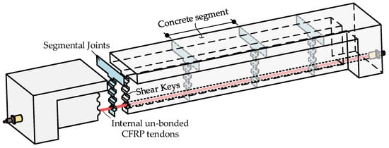
Figure 1.
Schematic diagram of internally un-bonded prestressed PSCB.
Numerical model analysis is a practical method generally adopted as an alternative to expensive, time-consuming experimental tests. In previous studies [25,36], a high-efficiency nonlinear computational procedure for the numerical analysis of PSCB-IUCFRP was developed in OpenSees 2.5.0 software [37] by the authors [25]. The modeling scheme of the proposed model is shown in Figure 2. The features of this model are as follows:
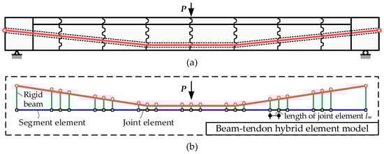
Figure 2.
Simulation scheme of the numerical model: (a) PSCB-IUCFRP system, (b) numerical model schematic diagram.
- The model included four kinds of elements: free-slip tendon elements, segment elements, joint elements, and rigid beam connection elements.
- The free-slip tendon element was a newly developed element type for un-bonded tendons. Considering the un-bonded phenomenon, the tendon stress was uniformly distributed along the whole tendon length, as shown in Figure 3a.
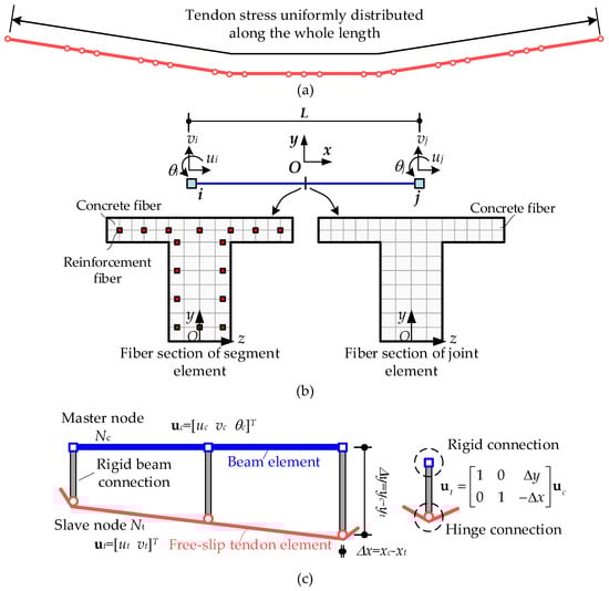 Figure 3. Element types in the developed numerical model: (a) free-slip tendon element, (b) fiber beam element for concrete segment and joint element, (c) rigid beam connection element.
 - The segment and joint element were all modeled by the displacement-based fiber beam element, as shown in Figure 3b. For the joint element, considering the joint discontinuity, the fiber section contained no reinforcement fiber, and the tensile strength of the concrete fiber was also ignored.
- The rigid beam connection element was employed to model the interaction between the beam and free-slip tendon elements.
- All elements were one-dimensional element types, reducing the number of degrees of freedom and significantly improving the computational efficiency. We considered all critical mechanical behaviors in the model, such as material nonlinearity, geometric nonlinearity, open joint discontinuity, and tendon free-slip effects. Details on the finite element formulas, constitutive model, and developed procedure can be seen in the previous studies [25,36].
2.2. Numerical Model Validation and Flexural Performances Comparisons
The flexural behaviors of three different prestressed concrete beams are compared with the numerical model. The configurations of these beams are shown in Table 1. The specimen BC1 reported by Le et al. [21] is taken as a case study to verify the effectiveness of the numerical model. BC1 is a PSCB prestressed by internal un-bonded CFRP tendons, and the design details are shown in Figure 4. The other two beams, M-CFRP and S-Steel, are analyzed for comparison. The M-CFRP beam has the same configurations as BC1, except that the beam is monolithic rather than segmental. The S-Steel beam is designed by replacing the CFRP tendons in BC1 with steel tendons. The comparisons between the results of BC1 and M-CFRP will therefore show the impact of segmental joints on flexural performances. The comparisons between the results of BC1 and S-Steel will display the effects of tendon type.

Table 1.
Configuration of the contrasting beams.
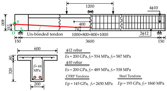
Figure 4.
Design details of specimen BC1 (unit: mm).
The load-deflection curves are shown in Figure 5a, and the tendon stress increment vs. mid-span deflection curves are shown in Figure 5b. The following comparisons can be made:
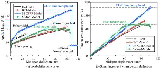
Figure 5.
Comparisons of flexural behavior of beams.
- Failure in BC1 is caused by concrete crushing. The CFRP tendon is still elastic, consistent with the experimental observations. The calculated values for structural deformation, capacity, and tendon stress all agreed well with the experimental results, verifying the effectiveness of the numerical model.
- Without the segmental joints, the M-CFRP beam shows a larger flexural capacity than beam BC1. Under the same mid-span deflection, the tendon stress increment of the monolithic beam M-CFRP is larger than that of the segmental beam BC1. The failure mode is changed to CFRP tendon rupture. These differences demonstrate the effects of segmental joints on flexural performance, which should be considered in capacity prediction.
- For the S-Steel beam, structural failure is caused by the steel tendon yielding and then concrete crushing, which is different from the BC1 beam. The effects of the tendon type are non-negligible when predicting flexural capacity.
- Figure 5b shows that the relationship between tendon stress increment and mid-span deflection is almost linear before tendon failure. The slope of the linear relationship is affected by the tendon type and segmental joints. The stress increments of steel tendons in the beam S-Steel are more significant than the CFRP tendon in the beam BC1 due to the steel tendon’s higher elastic modulus than the CFRP tendon. The comparisons between the M-CFRP and BC1 beams show that the tendon stress increments in the segmental beam are lower than the monolithic one.
- The sectional curvature distribution and deflection curves along the beam length are extracted from the analysis results to address the effects of segmental joints on the tendon stress increment, as shown in Figure 6. We find that the plastic deformations only occur at the mid-span joint section, and the other regions are almost elastic. However, the plastic deformations are distributed within the flexural span for the monolithic beam M-CFRP. The un-bonded tendon elongation is associated with the whole beam deformation, causing the differences in tendon stress increments between the monolithic and segmental beams.
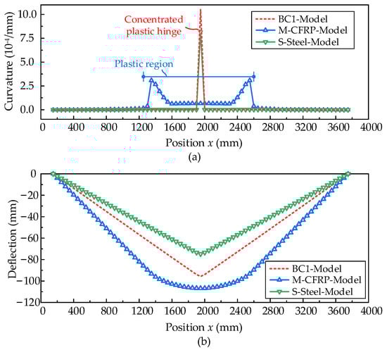 Figure 6. Sectional curvature distribution and deflection curves at ultimate state: (a) sectional curvature distribution at ultimate state, (b) deflection curves at ultimate state.
However, the previously reported flexural capacity prediction equations were built based on un-bonded prestressed monolithic beams, and some equations did not distinguish the tendon type. The applicability of these equations for newly developed PSCB-IUCFRP is not clear, and validation is required.
2.3. Parametric Analysis Study
Once the numerical model is validated, parametric analysis studies are conducted to clarify the main influence parameters of the flexural behaviors of PSCB-IUCFRP. At the same time, the numerical model results can be employed to build a database to evaluate the applicability of the prediction models.
The dimensions of the beam used for parametric analysis are shown in Figure 7. The main influence parameters for un-bonded prestressed members are considered in this study, including the span-to-depth ratio L/dp, prestressing reinforcement ratio ρp, effective prestressing stress σpe, concrete strength fc, and loading types. For the parameter L/dp, which varies from 11.0 to 24.5, the span length L is varied, while the cross-section and the effective height dp remain unchanged. The segment length is 600 mm, and the number of segments can be determined by the specified span length L. The prestressing reinforcement ratio ρp varies from 0.13% to 0.26% by changing the area of prestressing tendon Ap. The parameter values are listed in Table 2. With the combinations of these parameter values, 162 FE models are built and analyzed. All models were loaded up to failure by displacement control analysis technology. The failure modes are all caused by concrete crushing, and no tendon rupture occurs. The analysis results, including the tendon stress increments ∆σp, ultimate displacement at mid-span umax, and flexural capacity Mu, are listed in Appendix A.
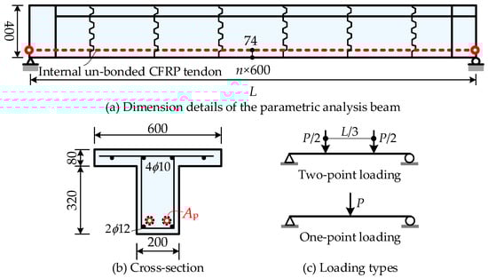
Figure 7.
Details of the beam used for parametric analysis (unit: mm).
Table 2.
Parameters and value range of the analyzed beam.
The analysis results of a group of numerical beams were plotted in Figure 8, Figure 9 and Figure 10 as examples, and some basic patterns can be observed as follows,
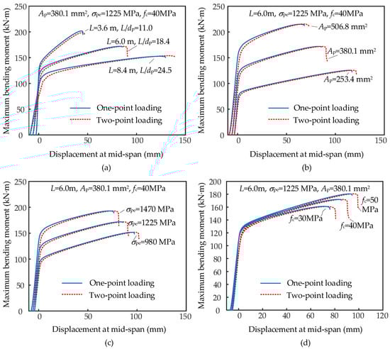
Figure 8.
Effects of parameters on the flexural behaviors of PSCB-IUCFRP: (a) effects of L/dp, (b) effects of Ap, (c) effects of σpe, (d) effects of fc.
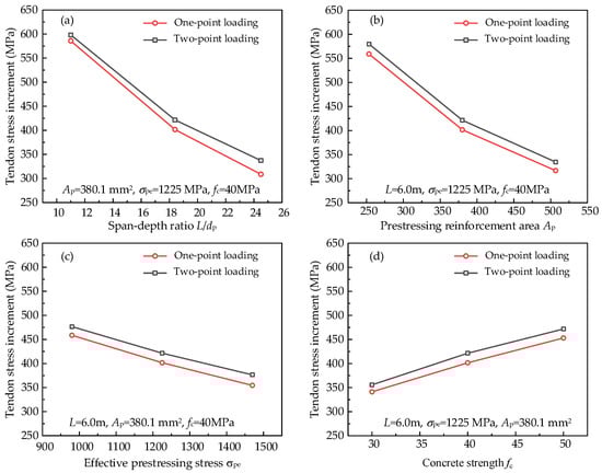
Figure 9.
Effects of parameters on the tendon stress increment of PSCB-IUCFRP: (a) effects of L/dp, (b) effects of Ap, (c) effects of σpe, (d) effects of fc.
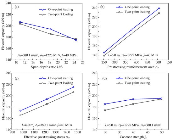
Figure 10.
Effects of parameters on the flexural capacity of PSCB-IUCFRP: (a) effects of L/dp, (b) effects of Ap, (c) effects of σpe, (d) effects of fc.
- Figure 8 shows the load-deflections curves of numerical beams under different loading patterns. The mid-span moment by the applied loads is set as the vertical coordinates in Figure 8 to make comparisons. As the loading patterns shown in Figure 7c, the vertical coordinate in Figure 8 is PL/6 for the two-point loading cases and PL/4 for the one-point loading cases. The loading types have a minor influence on the tendon stress increment and flexural capacity of PSCB-IUCFRP. This phenomenon differs from observations made in the experimental tests on monolithic beams [38,39]. The reason for this is that the plastic region of the segmental beam is concentrated at the failure joint cross-section, regardless of the loading type. In contrast, they are distributed across a monolithic beam. The different deformation modes between segmental and monolithic beams caused the difference.
- Figure 9 shows the effects of parameters on the tendon stress increment. With the increase in the parameters L/dp, Ap, and σpe, the tendon stress increments decrease. The effects of fc on the tendon stress increments are positive. The sensitivity of tendon stress increments to L/dp and Ap is more prominent than the other parameters.
- Figure 10 shows the effects of parameters on the flexural capacity. The parameter L/dp has a negative correlation with flexural capacity. In comparison, the flexural capacity increases with increasing parameters Ap, σpe, and fc.
Therefore, the effects of loading types can be ignored when predicting the flexural capacity of PSCB-IUCFRP, and the parameters L/dp, Ap, σpe, and fc should be considered.
3. Flexural Capacity Prediction Methods and Applicability Analysis
In this section, the widely used flexural capacity prediction methods for un-bonded prestressed beams are reviewed in brief. Then, the applicability of these methods is discussed based on the results of the 162 numerical model. Finally, a proposed prediction of the flexural capacity of PSCB-IUCFRP is put forward based on the collapse mechanism analysis.
3.1. Widely Used Methods for Predicting Flexural Capacity
The strain and stress distribution at the failure cross-section for an un-bonded prestressed concrete beam can be plotted, as in Figure 11. Unlike in bonded prestressed beams, the un-bonded tendons mostly do not reach tensile strength fpy but have a stress increment at the ultimate states. Generally, the tendon stress σp can be denoted as the sum of effective stress σpe and the stress increment ∆σp, as shown in Equation (1). The ultimate tendon stress increment is the critical variable yet to be predicted for the flexural capacity calculation. Currently, there are three main kinds of widely used prediction methods: statistical-based methods [40], bond-reduction methods [39,41,42], and deformation-based methods [29,35,43,44,45].
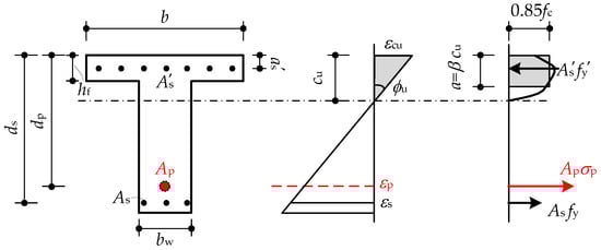
Figure 11.
Strain and stress distribution of the un-bonded prestressed beam.
3.1.1. Statistical-Based Method
The statistical-based method was usually built by the regression analysis of test data or numerical model results. The most representative model was the ACI 318-14′s equation [40]. It was initially proposed by Mattock et al. [46] based on the statistical analysis of tests of monolithic beams prestressed with un-bonded steel tendons. Mojtahedi and Gamble [47] subsequently improved the equations by introducing the effects of the span-depth ratio L/dp.
3.1.2. Bond-Reduction Method
The bond-reduction method was introduced by Naaman and Alkhairi [39]. This method’s basic idea was to take the strain increment of the un-bonded tendon as the product of the bond-reduction factor Ωu and adjacent concrete fiber strain. The calculation for the un-bonded prestressed members can therefore be equivalent to that for the bonded prestressed ones. The pivotal factor Ωu was obtained by the statistical analysis of the results of tests on monolithic beams prestressed with steel tendons [39]. This equation was adopted by the ACI 440.4R [48]. The expression of this equation is shown in Equation (3), in which Ωu = 1.5/(L/dp) for one-point loading and Ωu = 3.0/(L/dp) for two-point/uniform loading.
3.1.3. Deformation-Based Method
The deformation-based method was built based on failure mechanism analysis. Roberts-Wollmann et al. [43] assumed that the elongation of the un-bonded tendon mainly occurred within the plastic region, and the sectional curvature was assumed constant within the plastic region of length lp. Their original equation is shown in Equation (4), where L0 denotes the initial tendon length. Following the recommendation of Tam and Pannell [49], they took the plastic hinge length lp = 10.5 cu, which was obtained from the observation of tests of monolithic beams prestressed with steel tendons. Ep = 200 GPa and εcu = 0.003 were substituted into Equation (4) to simplify it for application to steel tendons. The simplified equation is shown in Equation (5), where L0 is the initial tendon length. Equation (5) was adopted by AASHTO LRFD [50]. In this paper, Equation (5) is rewritten as Equation (6) to consider the elastic module difference between steel and CFRP tendon.
3.2. Applicability Evaluation of the Widely Used Prediction Equations
The deformation-based method was usually considered the most rational of these three prediction methods due to its clear physical significance. In the early version of AASHTO specifications [51], the bond-reduction method proposed by Naaman and Alkhairi [39] was recommended for the prediction of un-bonded tendon stress increment. However, the related provisions were replaced by the deformation-based method of Roberts-Wollmann et al. [43] in the revised specifications. All the methods were devised without considering the discontinuity of segmental joints. The applicability of these methods for PSCB-IUCFRP is here evaluated based on the 162 numerical model results.
Figure 12 shows the comparisons between predictions and FE numerical model results. The indexes Mean(Pre./FE) and COV(Pre./FE) are employed to evaluate the prediction accuracy and scattering. Mean(Pre./FE) is defined as the mean value of the ratios of predictions to numerical model results, and COV(Pre./FE) is defined as the related coefficient of variation (COV). When the index Mean(Pre./FE) is closer to one and COV(Pre./FE) is smaller, the applicability of the prediction equation is better.
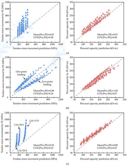
Figure 12.
Predictions of tendon stress increment and flexural capacity of the widely used equations: (a) ACI 318-14 model, (b) ACI 440.4R model, (c) AASHTO LRFD model. (circles represent the results of tendon stress increment and triangles denote the results of flexural capacity).
The predictions of tendon stress increment made by the ACI 318-14 model [40] are conservative and scattered, with a mean value of 0.67 and a COV value of 0.28. It is likely due to the fact that the equation was built based on a statistical analysis without any clear mechanism analysis. Moreover, the results from experimental tests of PSCB-IUCFRP were not included in the regression data. Even so, the ACI 318-14 model’s flexural capacity predictions seem acceptable. Although the tendon stress is underestimated, the length of the force arm (dp − a/2) is overestimated according to the axial force balance condition. As a result, the effects of the underestimation of tendon stress increment are reduced for flexural capacity prediction. However, this is not always guaranteed.
The predictions of the AASHTO LRFD method, derived from the failure mechanism analysis, are the most conservative and have a very poor correlation with the numerical analysis results. For the beams with the same L/dp, the tendon stress increment predictions are almost the same. We find that, with the assumed plastic hinge length lp = 10.5 cu by Roberts-Wollmann et al. [43], Equation (4) is transformed into Equation (6), and ∆σp is approximate to 0.031 Epdp/L0. We can infer that the assumption of plastic hinge length lp = 10.5 cu may not be suitable for PSCB-IUCFRP.
Unexpectedly, the bond-reduction method of Naaman and Alkhairi [39], which is replaced by the AASHTO LRFD specifications [50], gives a more accurate prediction than the other two methods. However, the predictions of tendon stress increment also show apparent variability. The cases under one-point loading tend to be underestimated, and those under two-point loading tend to be overestimated. The equations should be modified further, and the physical significance should be clarified.
3.3. Proposals for the Flexural Capacity Prediction Equation
The proposed flexural capacity prediction equation is based on an analysis of the failure mechanism. The failure mode of PSCB-IUCFRP, as determined by numerical analysis and experimental observation, is presented in Figure 13a. Under ultimate states, the failure joint cross-section will open significantly, and concrete crushing will occur at the compression flange. Structural deformation is mainly caused by plastic region deformation at the failure joint cross-section. The other region is still elastic, and the joints are almost closed.
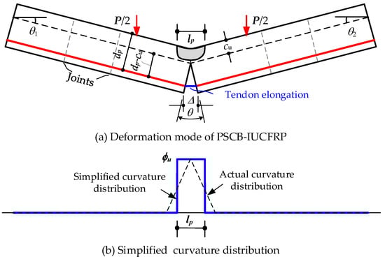
Figure 13.
Failure mechanism analysis of PSCB-IUCFRP.
Following Roberts-Wollmann et al. [43], tendon elongation mainly occurs at the failure joint cross-section. It is approximately equal to the width of the joint opening at the location of equal height. Therefore, the tendon elongation ∆ can be calculated by Equation (7), and the tendon strain increment can be expressed as Equation (8).
According to the ultimate curvature distribution obtained from the numerical model, the actual distribution mode shown in Figure 6a can be simplified into Figure 13b. The simplified curvature curve is uniformly distributed along the plastic region lp and set to zero for the other region. The structural rotation θ can therefore be expressed as,
Substituting Equation (9) into Equation (8) and following Hooke’s law, we can obtain the tendon stress increment, as shown in Equation (4). This means that the derivation by Roberts-Wollmann et al. [43] is applicable to PSCB-IUCFRP. As mentioned above, their unsatisfactory predictions are mainly caused by the assumption of plastic hinge length lp = 10.5 cu. This value was put forward by Tam and Pannell [49] through the back-calculating method based on only eight monolithic specimens. Au and Du [52] collected the test results of 148 specimens and concluded that the ratio of lp/cu ranged from 4 to 45 and showed a sizeable scattering distribution. The verification in Section 3.2 shows that the plastic hinge length value is unsuitable for PSCB-IUCFRP.
We assumed the plastic hinge length as a multiple of effective depth dp, lp = αdp. The tendon stress increment can be denoted as Equation (10), where εcu can be taken as 0.003 and cu can be calculated by combining Equation (10) and the axial force equilibrium equation [44].
Interestingly, we find that Equation (10), from the failure mechanism analysis, shows a similarity with the bond-reduction method Equation (3). Naaman and Alkhairi [39] obtained α = 2.6 for one-point loading and α = 5.4 for two-point/uniform loading based on the statistical analysis of collected specimen test results. For safety reasons, they conservatively modified the values to α = 1.5 for one-point loading and α = 3.0 for two-point/uniform loading. The modified values were adopted for code-type format in ACI 440.4R [48]. The predictions in Figure 12b show that the α value is conservative for one-point loading and overestimated for two-point loading. Moreover, the parametric analysis study in Section 2.3 shows that the loading types have a minor influence on the tendon stress increments and flexural capacity. The optimal α value is back-calculated based on the derived Equation (10) and the numerical analysis results. The values of α range from 1.5 to 3.0, and the effects of loading types are not considered. Table 3 shows the predictions of Equation (10) with different α values. It can be seen that the mean value index of flexural capacity predictions Mean(Pre./FE) is close to one, and the variability is acceptable. Therefore, α = 2.1 is recommended. The comparisons between the predictions and analysis results are shown in Figure 14.
Table 3.
Predictions of the proposed equation with different α values.
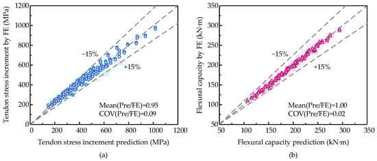
Figure 14.
Predictions of the proposed equation with the optimal value α = 2.1: (a) tendon stress increment prediction, (b) flexural capacity prediction. (circles represent the results of tendon stress increment and triangles denote the results of flexural capacity).
In summary, we recommend Equation (11) for predicting tendon stress increment in PSCB-IUCFRP. According to the schematic diagram in Figure 10, the axial force equilibrium can be expressed as Equation (12). The ultimate neutral axis height cu can be calculated with a combination of Equations (11) and (12), and ∆σp can also be predicted. The flexural capacity can be calculated by Equation (13).
The experimental results of specimens BC1 and BC2 reported by Le et al. are employed here to verify the proposed equations. The predictions made by Equations (2), (3), and (6) are listed for comparison, as shown in Table 4. The predictions by ACI 318-14 [40] and AASHTO LRFD [50] are overly conservative, and ACI 440.4R gives overestimated results. The predictions from the proposed equation show good agreement with the test results. The mean values of the ratio of predictions to experiments are 1.02 and 0.993 for tendon stress increment and flexural capacity, respectively.
Table 4.
Comparisons between predictions and experimental tests.
4. Discussion
4.1. Effects of Segment Size and Joint Positions
In PSCB, the segment size and joint positions affect the location of the failure cross-section. In practice, the joints are generally avoided to arrange at the mid-span, and the failure may occur at the joint cross-sections adjacent to the mid-span. The effects of segmental size and joint positions are discussed here.
Figure 15 shows three PSCB-IUCFRPs with the same span length of 8.4 m but different segment sizes. The cross-section details are shown in Figure 7 with the parameter values of Ap = 253.4 mm2, σpe = 980 MPa, and fc = 40 MPa. In Figure 15a,b, the segmental joint is not at the mid-span. Based on the numerical analysis results, the curvature distributions and failure modes at the ultimate states are shown in Figure 15. For beams Seg-7 and Seg-9, the tendon elongations occur at two joint cross-sections adjacent to the mid-span. However, the total elongations are close to the results of Seg-12, in which the failure occurs at one joint cross-section. When the segment size is small relative to the span length, the failure mode of Seg-7 and Seg-9 can be equivalent to the simple style shown in Figure 13 and Figure 15c. The proposed equations can also provide a simplified prediction for the tendon stress increment and flexural capacity. Figure 16 shows the load vs. tendon stress increment curves of three numerical beams and the predictions by the proposed equations. The results show that the tendon stress increments of three beams are close, and the prediction is on the safe side.
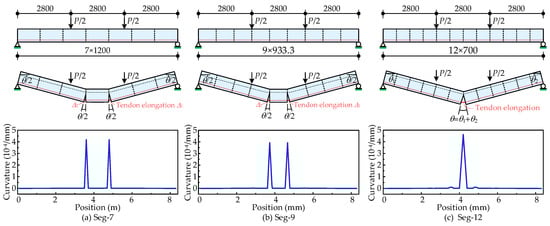
Figure 15.
Failure modes of PSCB-IUCFRP when failure cross-section not at the mid-span.
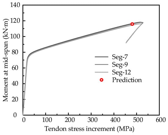
Figure 16.
Analysis and prediction results of PSCB-IUCFRP with different segment sizes.
4.2. Balanced Prestressing Reinforcement Ratio for PSCB-IUCFRP
The ACI 440.4R specifications introduced the balanced prestressing reinforcement ratio ρb for bonded members. With a balanced ratio, the tendon ruptures simultaneously with compression failure of the concrete. In this section, the balanced prestressing reinforcement ratio ρb is derived for PSCB prestressed with internal unbonded tendons based on the proposed prediction equations.
For beams with the balanced prestressing reinforcement ratio ρb, the compression block is generally within the depth of the flange at the ultimate states. Therefore, the following derivation is based on the assumption that cu < hf. According to the definition of ρb, the ultimate tendon stress reaches the tensile strength fpu. Therefore, Equations (11) and (12) can be rewritten as Equations (14) and (15), respectively.
With Equation (14), we can obtain the ultimate neutral axis height cu, as shown in Equation (16). By substituting Equation (16) into (15), the balanced prestressing reinforcement area can be denoted as Equation (17). The expression of ρb is obtained as Equation (18), the proposed balanced prestressing reinforcement ratio for PSCB-IUCFRP. The value of ρb is influenced by L0/dp, fc, and σpe parameters. An increase in fc and σpe will increase the value of ρb, while an increase in L0/dp will decrease ρb. In Equation (18), if we set κ = 1, we can obtain similar equations for ρb to those specified in ACI 440.4R for bonded prestressed members. The parameter κ in Equation (18) reflects the effects of the un-bonded property, which decreases the balanced prestressing reinforcement ratio ρb.
If the PSCB-IUCFRP beam is prestressed by a lower ratio of prestressing reinforcements than ρb, the beam will fail by tendon rupture. For cases with a higher ratio of prestressing reinforcements than ρb, then the failure mode will be concrete crushing. The balanced prestressing reinforcement area Ap calculated by Equation (17) is 116 mm2 for the second parametric analysis beam (ID = 2) listed in Table A1. The numerical model is then used to verify the prediction accuracy. Eight models are analyzed, using beam (ID = 2) as the reference beam and varying the parameter Ap from 100 mm2 to 135 mm2. The trend in tendon stress and mid-span deflection is shown in Figure 17. For beams prestressed by tendons with less than 120 mm2 area, the structural failure is caused by tendon rupture. Concrete crushing occurred at the ultimate state for beams with over 120 mm2 tendon area. The numerical results show that the balanced prestressing reinforcement area can be considered Ap = 120 mm2. The prediction error of Equation (17) is only (120 − 116)/120 = 3.33%. Therefore, Equations (17) and (18) are suggested for the structural design of PSCB-IUCFRP.
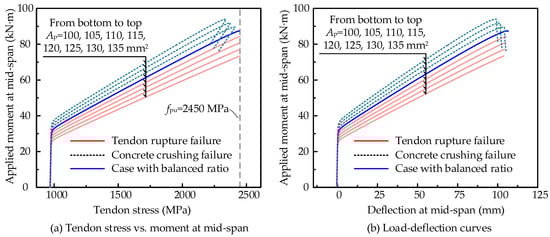
Figure 17.
Failure modes of the analysis beam with different prestressing ratios.
5. Conclusions
This paper studies the simplified equation for predicting tendon stress increment and flexural capacity in a precast segmental concrete beam with internally un-bonded prestressed CFRP tendons. Based on the developed numerical model, the effects of segmental joints and tendon type on flexural behaviors are analyzed. A parametric study containing 162 numerical models is conducted, and the analysis results are used to evaluate the widely used prediction equations for the PSCB-IUCFRP. Based on the failure mechanism analysis, new equations are put forward for predicting tendon stress increment, flexural capacity, and balanced prestressing reinforcement ratio for PSCB-IUCFRP. The main conclusions are as follows:
- The comparisons between segmental and monolithic beams show that plastic deformation in the segmental beam is concentrated at the failure joint cross-section, which differs from the monolithic beam’s distributed modes. With the same conditions, the monolithic beam’s stress increment, flexural capacity, and ultimate deflection are more significant than those of the segmental beam.
- The parametric study shows that the loading types have a minor influence on the tendon stress increment and flexural capacity of PSCB-IUCFRP. The factors L/dp, Ap, and σpe are negatively correlated with tendon stress increment. However, the factor fc has the opposite effect. The flexural capacity decreases with an increase in L/dp, and an increase in Ap, σpe, and fc improves the flexural capacity.
- The equations of the ACI 440.4R model, based on the bond-reduction method, show the best prediction accuracy for tendon stress increment with a mean index value of 0.98 and COV index value of 0.24. It underestimates the results of cases under one-point loading but overestimates those under two-point loading. The predictions of the ACI 318-14 model and the AASHTO LRFD model are all conservative.
- The predictions of the proposed equation, derived according to the failure mechanism and deformation analysis, show good agreement with the numerical model results for both tendon stress increment and flexural capacity. The simplified plastic hinge length for PSCB-IUCFRP is recommended to be 2.1 dp. The balanced prestressing reinforcement ratio of PSCB-IUCFRP is smaller than that of the bonded prestressed members, and the suggested equations are put forward.
Author Contributions
Conceptualization, methodology, software and validation, writing—original draft preparation, formal analysis, investigation, resources, data curation, writing—review and editing, W.Y.; visualization, writing—review and editing, Y.S.; supervision, writing—review and editing, L.C.; project administration, funding acquisition, writing—review and editing, F.J. All authors have read and agreed to the published version of the manuscript.
Funding
This research was funded by the Project of the Ministry of Housing and Urban-Rural Development No. K20200641; Fundamental Research Funds for the Central Universities, funding number 2022JBMC047; Project of Science and Technology Research Development Plan of China Railway, funding numbers N2021G046 and K2021G013; National Natural Science Foundation of China, funding number 51708020.
Institutional Review Board Statement
Not applicable.
Informed Consent Statement
Not applicable.
Data Availability Statement
Not applicable.
Conflicts of Interest
The authors declare no conflict of interest.
Appendix A
Table A1.
Analysis results of the parametric analysis beam.
Table A1.
Analysis results of the parametric analysis beam.
| ID | L (m) | Ap (mm2) | σpe (MPa) | fc (MPa) | Two-Point Loading | One-Point Loading | ||||
|---|---|---|---|---|---|---|---|---|---|---|
| ∆σp (MPa) | umax (mm) | Mu (kN·m) | ∆σp (MPa) | umax (mm) | Mu (kN·m) | |||||
| 1 | 3.6 | 253.4 | 980 | 30 | 780.3 | 58.8 | 133.5 | 771.3 | 58.2 | 135.5 |
| 2 | 3.6 | 253.4 | 980 | 40 | 892.5 | 66.0 | 144.1 | 876.0 | 64.6 | 146.1 |
| 3 | 3.6 | 253.4 | 980 | 50 | 981.6 | 71.5 | 152.8 | 964.7 | 70.1 | 154.7 |
| 4 | 3.6 | 253.4 | 1225 | 30 | 706.8 | 53.3 | 145.3 | 697.4 | 52.7 | 147.6 |
| 5 | 3.6 | 253.4 | 1225 | 40 | 811.6 | 59.9 | 156.1 | 801.9 | 59.3 | 158.4 |
| 6 | 3.6 | 253.4 | 1225 | 50 | 901.3 | 65.7 | 164.8 | 889.6 | 64.9 | 167.1 |
| 7 | 3.6 | 253.4 | 1470 | 30 | 644.1 | 48.6 | 157.7 | 625.9 | 47.1 | 160.2 |
| 8 | 3.6 | 253.4 | 1470 | 40 | 749.0 | 55.5 | 168.6 | 730.7 | 54.0 | 171.3 |
| 9 | 3.6 | 253.4 | 1470 | 50 | 829.4 | 60.5 | 177.5 | 818.6 | 59.8 | 180.1 |
| 10 | 3.6 | 380.1 | 980 | 30 | 573.7 | 44.0 | 171.5 | 563.0 | 43.3 | 174.1 |
| 11 | 3.6 | 380.1 | 980 | 40 | 664.5 | 49.9 | 185.4 | 652.7 | 49.1 | 188.0 |
| 12 | 3.6 | 380.1 | 980 | 50 | 734.7 | 54.3 | 196.4 | 723.9 | 53.6 | 199.2 |
| 13 | 3.6 | 380.1 | 1225 | 30 | 512.5 | 39.1 | 189.5 | 494.7 | 37.7 | 192.4 |
| 14 | 3.6 | 380.1 | 1225 | 40 | 598.1 | 44.8 | 203.6 | 585.7 | 44.0 | 206.6 |
| 15 | 3.6 | 380.1 | 1225 | 50 | 668.1 | 49.3 | 215.0 | 654.8 | 48.4 | 218.1 |
| 16 | 3.6 | 380.1 | 1470 | 30 | 454.8 | 34.1 | 208.2 | 441.8 | 33.3 | 211.5 |
| 17 | 3.6 | 380.1 | 1470 | 40 | 539.6 | 40.1 | 222.8 | 525.8 | 39.2 | 226.2 |
| 18 | 3.6 | 380.1 | 1470 | 50 | 608.3 | 44.8 | 234.3 | 589.8 | 43.4 | 237.9 |
| 19 | 3.6 | 506.8 | 980 | 30 | 461.8 | 35.7 | 205.8 | 444.9 | 34.4 | 208.7 |
| 20 | 3.6 | 506.8 | 980 | 40 | 533.7 | 40.3 | 222.6 | 521.1 | 39.5 | 225.6 |
| 21 | 3.6 | 506.8 | 980 | 50 | 596.8 | 44.5 | 236.0 | 584.2 | 43.7 | 239.2 |
| 22 | 3.6 | 506.8 | 1225 | 30 | 405.8 | 30.6 | 229.7 | 386.8 | 29.2 | 232.9 |
| 23 | 3.6 | 506.8 | 1225 | 40 | 477.4 | 35.7 | 247.1 | 462.2 | 34.7 | 250.5 |
| 24 | 3.6 | 506.8 | 1225 | 50 | 534.6 | 39.5 | 260.9 | 520.5 | 38.6 | 264.5 |
| 25 | 3.6 | 506.8 | 1470 | 30 | 357.3 | 25.8 | 254.8 | 339.8 | 24.7 | 258.2 |
| 26 | 3.6 | 506.8 | 1470 | 40 | 425.5 | 31.0 | 272.9 | 408.4 | 29.9 | 276.6 |
| 27 | 3.6 | 506.8 | 1470 | 50 | 482.3 | 35.2 | 287.1 | 465.5 | 34.1 | 291.1 |
| 28 | 6.0 | 253.4 | 980 | 30 | 558.7 | 115.8 | 117.7 | 546.8 | 113.9 | 125.9 |
| 29 | 6.0 | 253.4 | 980 | 40 | 640.3 | 130.3 | 125.9 | 627.2 | 128.3 | 132.2 |
| 30 | 6.0 | 253.4 | 980 | 50 | 712.3 | 143.7 | 132.5 | 684.0 | 137.6 | 130.9 |
| 31 | 6.0 | 253.4 | 1225 | 30 | 496.5 | 102.7 | 130.7 | 485.3 | 101.1 | 139.1 |
| 32 | 6.0 | 253.4 | 1225 | 40 | 579.8 | 118.2 | 139.0 | 559.0 | 114.1 | 145.6 |
| 33 | 6.0 | 253.4 | 1225 | 50 | 643.7 | 129.7 | 145.7 | 621.4 | 125.3 | 144.6 |
| 34 | 6.0 | 253.4 | 1470 | 30 | 444.4 | 91.5 | 144.2 | 428.1 | 88.5 | 152.9 |
| 35 | 6.0 | 253.4 | 1470 | 40 | 521.4 | 105.8 | 152.7 | 503.9 | 102.8 | 159.5 |
| 36 | 6.0 | 253.4 | 1470 | 50 | 584.2 | 117.4 | 159.4 | 566.2 | 114.4 | 154.8 |
| 37 | 6.0 | 380.1 | 980 | 30 | 409.3 | 85.6 | 154.7 | 394.9 | 83.1 | 165.2 |
| 38 | 6.0 | 380.1 | 980 | 40 | 476.6 | 98.1 | 165.4 | 458.6 | 94.9 | 173.7 |
| 39 | 6.0 | 380.1 | 980 | 50 | 532.2 | 108.4 | 174.0 | 509.5 | 103.9 | 174.6 |
| 40 | 6.0 | 380.1 | 1225 | 30 | 355.7 | 73.1 | 174.4 | 341.2 | 70.7 | 185.4 |
| 41 | 6.0 | 380.1 | 1225 | 40 | 421.4 | 85.9 | 185.5 | 401.6 | 82.3 | 194.0 |
| 42 | 6.0 | 380.1 | 1225 | 50 | 471.7 | 95.2 | 194.2 | 453.1 | 92.1 | 195.3 |
| 43 | 6.0 | 380.1 | 1470 | 30 | 316.5 | 63.6 | 195.0 | 297.4 | 60.1 | 206.5 |
| 44 | 6.0 | 380.1 | 1470 | 40 | 376.4 | 75.6 | 206.5 | 354.5 | 71.6 | 215.3 |
| 45 | 6.0 | 380.1 | 1470 | 50 | 425.6 | 85.1 | 215.4 | 405.0 | 81.6 | 188.5 |
| 46 | 6.0 | 506.8 | 980 | 30 | 328.0 | 68.2 | 188.7 | 311.5 | 65.2 | 201.4 |
| 47 | 6.0 | 506.8 | 980 | 40 | 383.7 | 78.8 | 201.9 | 364.5 | 75.3 | 211.6 |
| 48 | 6.0 | 506.8 | 980 | 50 | 428.8 | 87.2 | 212.4 | 408.7 | 83.7 | 214.9 |
| 49 | 6.0 | 506.8 | 1225 | 30 | 284.2 | 56.7 | 215.1 | 263.7 | 52.8 | 228.4 |
| 50 | 6.0 | 506.8 | 1225 | 40 | 334.6 | 66.9 | 228.9 | 316.8 | 64.0 | 239.0 |
| 51 | 6.0 | 506.8 | 1225 | 50 | 379.3 | 75.8 | 239.7 | 358.2 | 72.2 | 242.3 |
| 52 | 6.0 | 506.8 | 1470 | 30 | 250.4 | 46.8 | 242.6 | 229.0 | 43.0 | 256.5 |
| 53 | 6.0 | 506.8 | 1470 | 40 | 300.1 | 58.1 | 257.1 | 275.2 | 53.5 | 267.6 |
| 54 | 6.0 | 506.8 | 1470 | 50 | 340.2 | 66.5 | 268.3 | 315.6 | 62.1 | 254.1 |
| 55 | 8.4 | 253.4 | 980 | 30 | 444.8 | 180.9 | 109.6 | 430.2 | 176.1 | 108.9 |
| 56 | 8.4 | 253.4 | 980 | 40 | 512.4 | 204.5 | 116.5 | 493.0 | 197.8 | 115.6 |
| 57 | 8.4 | 253.4 | 980 | 50 | 570.4 | 225.5 | 122.0 | 547.6 | 217.1 | 121.0 |
| 58 | 8.4 | 253.4 | 1225 | 30 | 390.2 | 157.7 | 123.5 | 372.5 | 151.8 | 122.7 |
| 59 | 8.4 | 253.4 | 1225 | 40 | 459.6 | 183.6 | 130.3 | 435.4 | 174.5 | 129.4 |
| 60 | 8.4 | 253.4 | 1225 | 50 | 507.2 | 199.1 | 136.1 | 485.3 | 192.1 | 134.8 |
| 61 | 8.4 | 253.4 | 1470 | 30 | 339.9 | 135.7 | 137.8 | 326.9 | 132.3 | 137.1 |
| 62 | 8.4 | 253.4 | 1470 | 40 | 408.3 | 161.8 | 144.9 | 386.8 | 154.4 | 143.9 |
| 63 | 8.4 | 253.4 | 1470 | 50 | 459.0 | 180.1 | 150.5 | 293.2 | 112.0 | 140.7 |
| 64 | 8.4 | 380.1 | 980 | 30 | 321.8 | 130.9 | 146.4 | 306.1 | 125.9 | 145.1 |
| 65 | 8.4 | 380.1 | 980 | 40 | 377.1 | 151.0 | 155.5 | 285.7 | 111.9 | 148.2 |
| 66 | 8.4 | 380.1 | 980 | 50 | 426.4 | 169.9 | 162.6 | 400.5 | 160.2 | 160.8 |
| 67 | 8.4 | 380.1 | 1225 | 30 | 282.0 | 112.7 | 167.5 | 261.1 | 105.2 | 166.0 |
| 68 | 8.4 | 380.1 | 1225 | 40 | 337.3 | 134.2 | 176.8 | 308.7 | 123.3 | 175.0 |
| 69 | 8.4 | 380.1 | 1225 | 50 | 370.6 | 145.1 | 184.2 | 349.1 | 138.4 | 182.1 |
| 70 | 8.4 | 380.1 | 1470 | 30 | 244.9 | 94.3 | 189.4 | 222.1 | 86.3 | 187.8 |
| 71 | 8.4 | 380.1 | 1470 | 40 | 298.9 | 116.4 | 199.1 | 269.3 | 105.4 | 197.1 |
| 72 | 8.4 | 380.1 | 1470 | 50 | 334.3 | 129.4 | 206.6 | 307.8 | 120.5 | 204.4 |
| 73 | 8.4 | 506.8 | 980 | 30 | 258.1 | 103.3 | 180.7 | 239.1 | 96.9 | 178.7 |
| 74 | 8.4 | 506.8 | 980 | 40 | 306.1 | 122.0 | 191.9 | 282.3 | 113.5 | 189.4 |
| 75 | 8.4 | 506.8 | 980 | 50 | 342.5 | 135.2 | 200.8 | 318.7 | 127.3 | 197.9 |
| 76 | 8.4 | 506.8 | 1225 | 30 | 222.5 | 84.6 | 208.8 | 200.9 | 77.2 | 206.6 |
| 77 | 8.4 | 506.8 | 1225 | 40 | 267.3 | 103.1 | 220.6 | 241.7 | 94.1 | 217.9 |
| 78 | 8.4 | 506.8 | 1225 | 50 | 302.4 | 116.9 | 229.8 | 275.0 | 107.5 | 226.7 |
| 79 | 8.4 | 506.8 | 1470 | 30 | 196.6 | 69.2 | 237.9 | 171.3 | 60.2 | 235.4 |
| 80 | 8.4 | 506.8 | 1470 | 40 | 240.1 | 88.8 | 250.5 | 209.8 | 77.8 | 247.4 |
| 81 | 8.4 | 506.8 | 1470 | 50 | 274.3 | 103.3 | 260.1 | 240.2 | 90.9 | 256.6 |
References
- Tran, D.T.; Pham, T.M.; Hao, H.; Do, T.V.; Tran, T.T. Blast Behaviour of Precast Segmental vs. Monolithic Concrete Beams Prestressed with Unbonded Tendons: A Numerical Investigation. Int. J. Impact Eng. 2023, 173, 104434. [Google Scholar] [CrossRef]
- Zhang, Y.; Zhang, Z.; Hu, F.; Du, X.; Lu, Y.; Zhu, J. Full-Scale Experimental Study on Shear Behavior of Multiple-Keyed Epoxy Joints in Precast Concrete Segmental Bridges. Structures 2022, 45, 437–447. [Google Scholar] [CrossRef]
- Behrmann, T.; Frohlich, M.; Wenger, P.; Hierl, M. Technical Challenges in the Design of Prestressed Concrete Precast Beams with Dry and Smooth Joints in Bridge Construction. Bautechnik 2022, 99, 288–295. [Google Scholar] [CrossRef]
- Elsamak, G.; Salama, M.I.; Hamoda, A. Behavior of Precast Segmental Beams Made of High-Strength Concrete and Ultra-High Performance Fiber Concrete Connected by Shear Keys Technique. Arab. J. Sci. Eng. 2022, 48, 4907–4923. [Google Scholar] [CrossRef]
- Ahmed, G.H.; Aziz, O.Q. Shear Strength of Joints in Precast Posttensioned Segmental Bridges During 1959–2019, Review and Analysis. Structures 2019, 20, 527–542. [Google Scholar] [CrossRef]
- Yuen, T.Y.P.; Halder, R.; Chen, W.-W.; Zhou, X.; Deb, T.; Liu, Y.; Tseng, Y.; Wen, T.-H. DFEM of a Post-Tensioned Precast Concrete Segmental Bridge with Unbonded External Tendons Subjected to Prestress Changes. Structures 2020, 28, 1322–1337. [Google Scholar] [CrossRef]
- Jiang, H.; Hu, Z.; Cao, Z.; Gao, X.; Tian, Y.; Sun, X. Experimental and Numerical Study on Shear Performance of Externally Prestressed Precast UHPC Segmental Beams without Stirrups. Structures 2022, 46, 1134–1153. [Google Scholar] [CrossRef]
- Jiang, H.; Cao, Q.; Liu, A.; Wang, T.; Qiu, Y. Flexural Behavior of Precast Concrete Segmental Beams with Hybrid Tendons and Dry Joints. Constr. Build. Mater. 2016, 110, 1–7. [Google Scholar] [CrossRef]
- Jiang, H.; Li, Y.; Liu, A.; Chen, L.; Chen, Y.; Xiao, J. Experimental Study on Shear Behavior of Precast Concrete Segmental Beams with Hybrid Tendons and Dry Joints. KSCE J. Civ. Eng. 2019, 23, 4354–4367. [Google Scholar] [CrossRef]
- Anania, L.; Badalà, A.; D’Agata, G. Damage and Collapse Mode of Existing Post Tensioned Precast Concrete Bridge: The Case of Petrulla Viaduct. Eng. Struct. 2018, 162, 226–244. [Google Scholar] [CrossRef]
- Wouters, J.P.; Kesner, K.; Poston, R.W. Tendon Corrosion in Precast Segmental Bridges. J. Transp. Res. Board 1999, 1654, 128–132. [Google Scholar] [CrossRef]
- Woodward, R.; Williams, F. Collapse of Yns-Y-Gwas Bridge, Glamorgan. Proc. Inst. Civ. Eng. 1988, 84, 635–669. [Google Scholar] [CrossRef]
- Halder, R.; Yuen, T.Y.P.; Chen, W.-W.; Zhou, X.; Deb, T.; Zhang, H.; Wen, T.-H. Tendon Stress Evaluation of Unbonded Post-Tensioned Concrete Segmental Bridges with Two-Variable Response Surfaces. Eng. Struct. 2021, 245, 112984. [Google Scholar] [CrossRef]
- Jia, L.; Fang, Z.; Huang, Z.; Pilakoutas, K.; Wang, Q.; Tan, X. Flexural Behavior of UHPC Beams Prestressed with External CFRP Tendons. Appl. Sci. 2021, 11, 9189. [Google Scholar] [CrossRef]
- Rogowski, J.; Kotynia, R. Comparison of Prestressing Methods with CFRP and SMA Materials in Flexurally Strengthened RC Members. Materials 2022, 15, 1231. [Google Scholar] [CrossRef]
- Lou, T.; Lopes, S.M.R.; Lopes, A.V. External CFRP Tendon Members: Secondary Reactions and Moment Redistribution. Compos. Part B 2014, 57, 250–261. [Google Scholar] [CrossRef]
- Lou, T.; Lopes, S.M.R.; Lopes, A.V. Factors Affecting Moment Redistribution at Ultimate in Continuous Beams Prestressed with External CFRP Tendons. Compos. Part B 2014, 66, 136–146. [Google Scholar] [CrossRef]
- Lou, T.; Lopes, S.M.R.; Lopes, A.V. A Comparative Study of Continuous Beams Prestressed with Bonded FRP and Steel Tendons. Compos. Struct. 2015, 124, 100–110. [Google Scholar] [CrossRef]
- Lou, T.; Liu, M.; Lopes, S.M.R.; Lopes, A.V. Effect of Bond on Flexure of Concrete Beams Prestressed with FRP Tendons. Compos. Struct. 2017, 173, 168–176. [Google Scholar] [CrossRef]
- Lou, T.; Karavasilis, T.L. Time-Dependent Assessment and Deflection Prediction of Prestressed Concrete Beams with Unbonded CFRP Tendons. Compos. Struct. 2018, 194, 365–376. [Google Scholar] [CrossRef]
- Le, T.D.; Pham, T.M.; Hao, H.; Haoc, Y. Flexural Behaviour of Precast Segmental Concrete Beams Internally Prestressed with Unbonded CFRP Tendons under Four-Point Loading. Eng. Struct. 2018, 168, 371–383. [Google Scholar] [CrossRef]
- Le, T.D.; Pham, T.M.; Hao, H.; Yuan, C. Performance of Precast Segmental Concrete Beams Posttensioned with Carbon Fiber-Reinforced Polymer (CFRP) Tendons. Compos. Struct. 2019, 208, 56–69. [Google Scholar] [CrossRef]
- Le, T.D.; Pham, T.M.; Hao, H.; Li, H. Behavior of Precast Segmental Concrete Beams Prestressed with External Steel and CFRP Tendons. J. Compos. Constr. 2020, 24, 04020053. [Google Scholar] [CrossRef]
- Tran, D.T.; Pham, T.M.; Hao, H.; Chen, W. Numerical Investigation of Flexural Behaviours of Precast Segmental Concrete Beams Internally Post-Tensioned with Unbonded FRP Tendons under Monotonic Loading. Eng. Struct. 2021, 249, 113341. [Google Scholar] [CrossRef]
- Yan, W.; Chen, L.; Han, B.; Xie, H.; Sun, Y. Numerical Model for Flexural Analysis of Precast Segmental Concrete Beam with Internal Unbonded CFRP Tendons. Materials 2022, 15, 4105. [Google Scholar] [CrossRef] [PubMed]
- Ghallab, A. Calculating Ultimate Tendon Stress in Externally Prestressed Continuous Concrete Beams Using Simplified Formulas. Eng. Struct. 2013, 46, 417–430. [Google Scholar] [CrossRef]
- Maguire, M.; Chang, M.; Collins, W.N.; Sun, Y. Stress Increase of Unbonded Tendons in Continuous Posttensioned Members. J. Bridge Eng. 2017, 22, 04016115. [Google Scholar] [CrossRef]
- Alqam, M.; Alkhairi, F.; Naaman, A. An Improved Methodology for the Prediction of the Stress at Ultimate in Unbonded Internal and External Steel Tendons. Arab. J. Sci. Eng. 2020, 45, 7915–7954. [Google Scholar] [CrossRef]
- Yan, W.-T.; Chen, L.-J.; Han, B.; Wei, F.; Xie, H.-B.; Yu, J.-P. Proposals for Flexural Capacity Prediction Method of Externally Prestressed Concrete Beam. Struct. Eng. Mech. 2022, 83, 363–375. [Google Scholar]
- Lee, C.; Shin, S.; Lee, H. Balanced Ratio of Concrete Beams Internally Prestressed with Unbonded CFRP Tendons. Int. J. Concr. Struct. Mater. 2017, 11, 1–16. [Google Scholar] [CrossRef]
- Sun, Y.; Wu, T.; Liu, X. Design of Concrete Beams Reinforced and Unbonded Prestressed with FRP Bars Based on Serviceability Requirements. Compos. Struct. 2022, 300, 116133. [Google Scholar] [CrossRef]
- Sun, Y.; Wu, T.; Liu, X.; Zhang, B. Failure Mode and Flexural Capacity of Concrete Beams Prestressed with Unbonded FRP Tendons. Compos. Struct. 2022, 283, 114956. [Google Scholar] [CrossRef]
- Fu, C.; Zhu, Y.; Wang, Y. Stiffness Assessment of Cracked Post-Tensioned Concrete Beams with Unbonded Tendons Based on the Cracking Pattern. Eng. Struct. 2020, 214, 110599. [Google Scholar] [CrossRef]
- Zhou, W.; Xie, X. Flexural Response of Continuous Unbonded Post-Tensioned Beams Strengthened with CFRP Laminates. Compos. Struct. 2019, 211, 455–468. [Google Scholar] [CrossRef]
- Peng, F.; Xue, W. Calculating Method for Ultimate Tendon Stress in Internally Unbonded Prestressed Concrete Members. ACI Struct. J. 2019, 116, 225–234. [Google Scholar] [CrossRef]
- Yan, W.-T.; Han, B.; Xie, H.-B.; Li, P.-F.; Zhu, L. Research on Numerical Model for Flexural Behaviors Analysis of Precast Concrete Segmental Box Girders. Eng. Struct. 2020, 219, 110733. [Google Scholar] [CrossRef]
- Mckenna, F.; Fenves, G. Opensees 2.5.0, Computer Software; UC Berkeley: Berkeley, CA, USA, 2015; Available online: http://opensees.berkeley.edu (accessed on 1 March 2023).
- Naaman, A.E.; Alkhairi, F.M. Stress at Ultimate in Unbonded Post-Tensioning Tendons. Part 1-Evaluation of the State-of-the-Art. ACI Struct. J. 1991, 88, 641–651. [Google Scholar]
- Naaman, A.E.; Alkhairi, F.M. Stress at Ultimate in Unbonded Post-Tensioning Tendons: Part 2-Proposed Methodology. ACI Struct. J. 1991, 88, 683–692. [Google Scholar]
- ACI 318-14; Building Code Requirements for Reinforced Concrete (ACI 318-14). American Concrete Institute: Detroit, MI, USA, 2014.
- Chee-Khoon, N. Tendon Stress and Flexural Strength of Externally Prestressed Beams. ACI Struct. J. 2003, 100, 644–653. [Google Scholar]
- He, Z.Q.; Liu, Z. Stresses in External and Internal Unbonded Tendons: Unified Methodology and Design Equations. J. Struct. Eng. 2010, 136, 1055–1065. [Google Scholar] [CrossRef]
- Roberts-Wollmann, C.L.; Kreger, M.E.; Rogowsky, D.M.; Breen, J.E. Stresses in External Tendons at Ultimate. ACI Struct. J. 2005, 102, 206–213. [Google Scholar]
- Lee, S.-H.; Shin, K.-J.; Thomas, H.K.K. Non-Iterative Moment Capacity Equation for Reinforced Concrete Beams with External Post-Tensioning. ACI Struct. J. 2014, 111, 1111–1122. [Google Scholar] [CrossRef]
- Peng, F.; Xue, W.; Tan, Y. Design Approach for Flexural Capacity of Prestressed Concrete Beams with External Tendons. J. Struct. Eng. 2018, 144, 04018215. [Google Scholar] [CrossRef]
- Alan, H.; Mattock, J.Y.; Basil, T.K. Comparative Study of Prestressed Concrete Beams, with and without Bond. J. Proc. 1971, 68, 116–125. [Google Scholar]
- Mojtahedi, S.; Gamble, W.L. Ultimate Steel Stresses in Unbonded Prestressed Concrete. J. Struct. Div. 1978, 104, 1159–1165. [Google Scholar] [CrossRef]
- ACI 440.4R; Prestressing Concrete Structures with FRP Tendons. American Concrete Institute: Farmington Hills, MI, USA, 2004.
- Tam, A.; Pannell, F.N. Ultimate Moment Resistance of Unbonded Partially Prestressed Reinforced Concrete Beams. Mag. Concr. Res. 1976, 28, 203–208. [Google Scholar] [CrossRef]
- AASHTO. AASHTO LRFD Bridge Design Specifications; AASHTO: Washington, DC, USA, 2017. [Google Scholar]
- AASHTO. Bridge Design Specification; AASHTO: Washington, DC, USA, 1994. [Google Scholar]
- Au, F.T.K.; Du, J. Prediction of Ultimate Stress in Unbonded Prestressed Tendons. Mag. Concr. Res. 2004, 56, 1–11. [Google Scholar] [CrossRef]


Disclaimer/Publisher’s Note: The statements, opinions and data contained in all publications are solely those of the individual author(s) and contributor(s) and not of MDPI and/or the editor(s). MDPI and/or the editor(s) disclaim responsibility for any injury to people or property resulting from any ideas, methods, instructions or products referred to in the content. |
© 2023 by the authors. Licensee MDPI, Basel, Switzerland. This article is an open access article distributed under the terms and conditions of the Creative Commons Attribution (CC BY) license (https://creativecommons.org/licenses/by/4.0/).