Article

Theoretical Method to Predict Internal Force of Crossbeam in Steel–Concrete Composite Twin I-Girder Bridge under Torsional Loading

1
School of Highway, Chang’an University, Xi’an 710064, China
2
School of Civil Engineering, Chongqing University, Chongqing 400044, China
*
Author to whom correspondence should be addressed.
Appl. Sci. 2023, 13(11), 6669; https://doi.org/10.3390/app13116669
Submission received: 27 March 2023 / Revised: 22 May 2023 / Accepted: 29 May 2023 / Published: 30 May 2023
(This article belongs to the Special Issue Structural Design and Analysis for Constructions and Buildings)

Abstract

:
During the operational phase of a bridge, the crossbeam, acting as a supporting member, plays an important role in keeping the cross-sectional shape constant in addition to resisting against various lateral and longitudinal loads and distributing the dead and the live loads to the adjacent main girders. The complex functional requirements lead to a complex internal force composition of the crossbeam. When subjected to torque, the two main beams of the twin I-girder bridge will have deformation in opposite longitudinal directions (known as warping deformation) to counteract the torque. The existing research has not considered the impact of main beam warping deformation on the internal force of the crossbeam. Based on the existing research, this article further considers the impact of main beam warping deformation on the internal force of the crossbeam, making the calculation of the internal force of the crossbeam more accurate. The results show that the torsional characteristics of the continuous twin I-girder bridge can be calculated using Vlasov’s theory of thin-walled structures combined with the displacement method. As for the effect of the crossbeam on the torsional stiffness of the structure, it can be managed by making the crossbeam stiffness continuous; however, in general, the equivalent stiffness is small compared to the stiffness of the main beam and it can be ignored. The crossbeam can be simplified to a bar with two solid ends for the internal force calculation whose formula is proposed in this paper, based on the existing frame model, and it can further consider the influence of warping deformation of the main beam on the internal force of the beam, and the calculation accuracy is high.

1. Introduction

Steel-concrete composite girder bridges are widely used in motorway and municipal bridges because they make full use of the properties of each material and have a high load-bearing capacity. The twin I-girder bridge has many advantages, such as easy and efficient construction, high industrialisation, simple structure construction, and high technology economy [1,2,3]. This type of bridge has been used in many applications. In fact, in this structure, the bracing system is part of the bridge load-bearing system, which not only provides overall stability for the main girders during the construction phase, but also withstands various lateral loads during the operational phase [4,5,6,7,8]. In the case of twin I-beam bridges, the cross frames’ dimensions need to be increased to meet the stability requirements due to the large spacing of the main girders [9], whereas the crossbeams are simpler and more convenient to construct than cross frames.
The crossbeam in twin I-girder bridges is subjected to horizontal forces brought on by wind loads and, in some cases, by the lateral torsional buckling of the compression member acting as a support. In the case of curved beams, the crossbeam is also subjected to the horizontal radial component of the axial force of the main beam because of the curvature of the curved beam [10]. The internal force components of the crossbeam are therefore mainly related to the distribution and the magnitude of these types of loads. At present, a series of studies has been carried out on the internal forces of crossbeams. The internal forces in crossbeams can be determined approximately using the V-load method. In fact, Peollet [11] documented the development of the V-load method. As for Liu and Magliola [12], they concluded that, in the analysis of horizontally curved steel beams, the crossbeam forces can be determined according to the V-load method if the effects of curvature can be ignored. In addition, these authors present tables for the calculation of crossbeam end moments and shear forces for structures with 2 to 8 main beams and carry out internal beam force calculations using an example of a 5-main beam structure design. Gaylord et al. [13] have also made use of the V-load method for the design of engineering examples. Grubb [14] extended the V-load method to the I-girder with arbitrary bracing structures and compared the results of the V-load method with finite element calculations for structures with three different lateral bracing systems under dead and live loads. It was shown that the results of the V-load method are relatively accurate under dead load, while, under live load, the outcomes are influenced by the lateral distribution of the load. Another conclusion was reached showing that the V-load method cannot be applicable to a closed-framed system with horizontal lateral bracing near, or in, the plane of the bottom flanges, as this would inhibit the lateral bending effect of the flange and, therefore, the V-load method would produce less accurate results [15,16]. However, for twin I-girder bridges, the most common calculation method used by scholars is to simplify the spatial structure of the bridge consisting of steel main girders, cross girders, and deck slabs to a planar frame model in order to facilitate the calculation process. In their publication, Xiang and Liu [17] studied the distribution of transverse moments in concrete slabs with crossbeam sections under external loads and proposed a frame model for crossbeam sections to analyse the transverse moment distribution coefficients. These coefficients can calculate the internal forces and moments of crossbeams under vertical loads on bridge deck slabs; however, the model is only applicable to the case where vertical loads are applied to the bridge deck slabs. The simplified frame model, proposed by Lebet and Hirt [10], takes into consideration the effects of lateral horizontal wind loads or lateral horizontal component forces due to curvature effects; however, the frame model only considers forces in the frame plane.
For the continuous twin I-girder bridge presented in Figure 1, under bending strain, the two main beams deform evenly, while the crossbeam does not deform in the direction of the longitudinal bridge. However, when subjected to a torque, the two main beams will deform in the opposite longitudinal bridge direction to counteract the torque, and the crossbeam will deform in the longitudinal bridge direction as a result of the coordination of their respective deformations. The crossbeam is welded to the vertical stiffening ribs, which is equivalent to a solid end restraint at both ends when considering the crossbeam. Whenever the crossbeam deforms in the longitudinal bridge direction, the corresponding internal forces must be generated in its cross-section.
Therefore, it is necessary to calculate the impact of main beam’s warping deformation on the internal forces of the crossbeam under torsional loading. This paper is based on Vlasov’s theory of thin-walled structures to obtain the torsional properties of continuous beams. It is assumed that the deformation between the main beam and the crossbeam is coordinated, and the deformations in the longitudinal bridge direction of the main beam are transformed into deformations at the ends of the crossbeam. Finally, the crossbeam is simplified to a bar system model to derive the internal force calculation equations.

2. Torsional Effect of Continuous Twin I-Girder Bridge

2.1. Section Conversion for Torsion Analysis of Composite Beams

Several basic assumptions are first made for the analysis of constrained torsion in open composite beams. These assumptions are the following:
(1)
the section profile is not deformed in its plane under small deformations;
(2)
the shear strain on the middle face of the bar is zero;
(3)
the slip effect between the steel beam and the concrete is ignored (as the slip effect has a great impact on the structural stiffness [18,19,20]);
(4)
both steel and concrete are ideal linear elastic materials.
Starting from the basic assumptions, the deformation and the stress state of an open thin-walled bar are discussed. The warping displacement at any point on the cross-section can be defined as: u x , s = φ x ω s , where φ represents the torsion angle rate, ω is the principal sectoral coordinate of the cross-section and s is the cross-sectional curve coordinate.
Referring to the relationship between the warping displacement and the longitudinal normal strain of the micro-element and Hooke’s law, the longitudinal warping normal stress can be found as follows σ w = E 1 φ ( x ) ω s where E1 is called the commuted modulus of elasticity of the thin-walled rod and is obtained from the first basic assumption and Hooke’s law E 1 = E 1 μ 2 , where E is Young’s modulus of the material. As μ is generally very small, we can consider that E 1 = E .
Similar to the generalized forces in primary beam theory M x = F σ y d F , the generalized force-warping bimoment is defined in constrained torsion B = F σ ω ω d F . For composite beams, one can write:
B = A σ ω ω d A = A s σ s ω ω d A s + A c σ c ω ω d A c
where σ s ω and σ c ω represent, respectively, the warping normal stress of the steel girder and concrete deck, and A s and A c represent, respectively, the cross-sectional areas of the steel girder and concrete deck. Substituting the warping normal stress equation σ w = E 1 φ ( x ) ω s to Equation (1), we get:
B = E s 1 φ ( x ) A s ω 2 d A s E c 1 φ ( x ) A c ω 2 d A c
Equation (2) can be written as follows:
B = E s 1 φ ( x ) A s ω 2 d A s + 1 α E A c ω 2 d A c
Therefore, the principal sectoral moment of inertia of the steel-concrete section is:
I ω , u n = A s ω 2 d A s + 1 α E A c ω 2 d A c
where α E is the modulus of elasticity ratio α E = E s 1 E c 1 .
However, Equation (4) can be written in another form as follows:
I ω , u n = A s ω 2 d A s + 1 α E A c ω 2 d A c = t s A s ω 2 d s + t c α E A c ω 2 d s = t s A s ω 2 d s + t c A c ω 2 d s
where t s and t c represent, respectively, the actual thickness of the steel girder and concrete deck, and t c is the equivalent thickness of the concrete deck.
From the above equation, the section should be converted by fixing the width of the concrete deck slab and changing only its thickness; thus, the sectoral coordinates of the section will remain constant even after the conversion. Kollbrunner and Basler [21] also mentioned this point, justifying such a conversion (as shown in Figure 2). According to the second basic assumption, thin-walled bars are calculated with reference to the centre line of the section.

2.2. Application of the Displacement Method to the Analysis of Constrained Torsion in Continuous Beams

In solving the internal forces of a plane rigid frame by the displacement method, there are three general problems to be solved:
(1)
Determine which displacements on the structure are to be used as the basic unknown quantities;
(2)
Work out the internal forces of a single-span statically indeterminate bar when various displacements and loads occur at the rod ends;
(3)
Calculate these displacements.
The following is a discussion of the differences between the application of the displacement method in thin-walled rod structures and in general structures, starting with these three problems in turn.
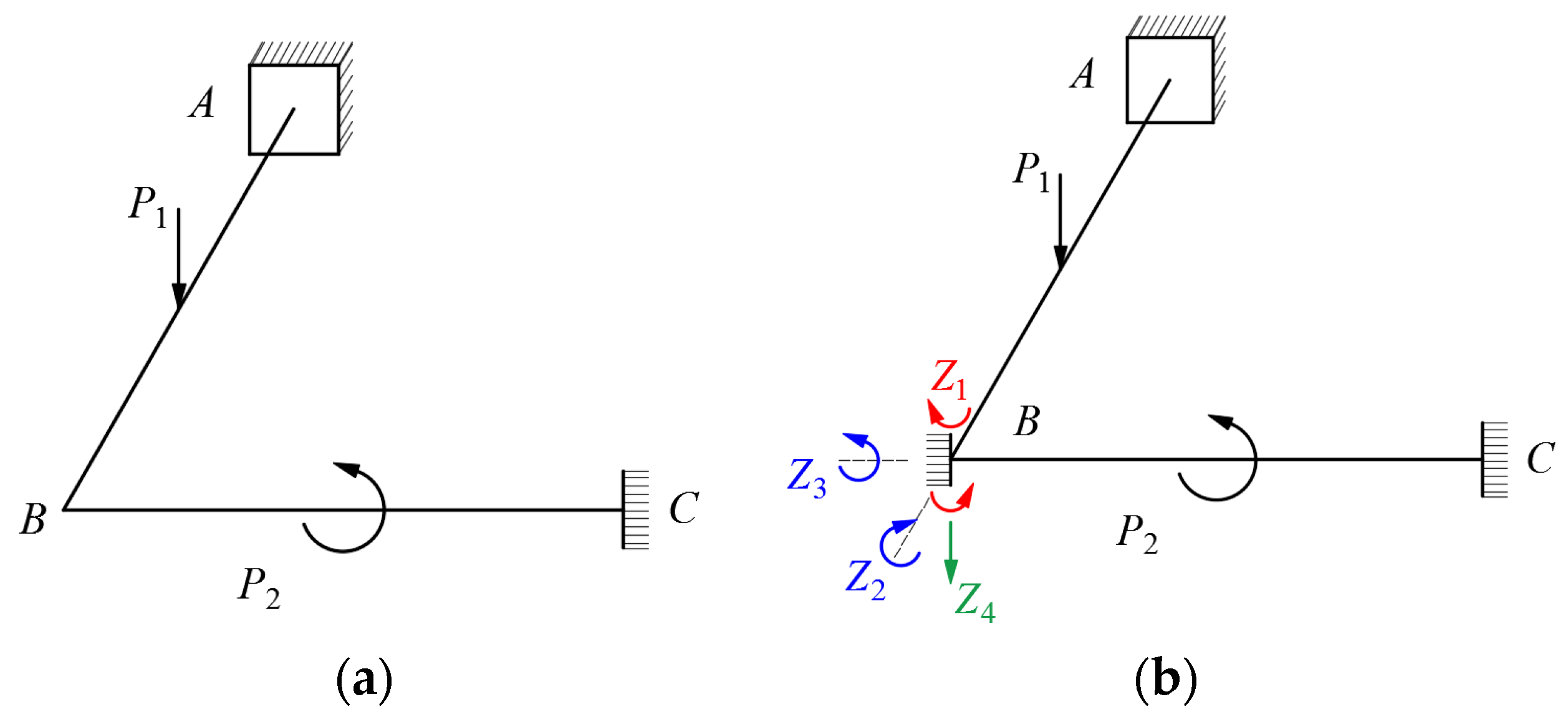
The application of the displacement method to restrain torsion in thin-walled structures is illustrated by the example of a planar rigid frame structure as shown in Figure 3a. Since there is no torsion in the rigid frame’s bars when it is subjected to loads in its plane, the torsion characteristics of the thin-walled bars are not shown; however, when the plane rigid frame is subjected to out-of-plane loads, there is also the warping deformation Z4 of the node section in addition to the linear displacement Z1 perpendicular to the plane of the rigid frame, the angular displacement Z2 around the AB bar, and the angular displacement Z3 around the BC bar (since the warping of the section is proportional to the torsion angle rate φ , it can be expressed using φ ). The basic system of a planar rigid frame is shown in Figure 3b; with additional constraints at node B, the basic equation of the displacement method can be obtained as shown in system (6).
r 11 Z 1 + r 12 Z 2 + r 13 Z 3 + r 14 Z 4 + R 1 p = 0 r 21 Z 1 + r 22 Z 2 + r 23 Z 3 + r 24 Z 4 + R 2 p = 0 r 31 Z 1 + r 32 Z 2 + r 33 Z 3 + r 34 Z 4 + R 3 p = 0 r 41 Z 1 + r 42 Z 2 + r 43 Z 3 + r 44 Z 4 + R 4 p = 0
The above structure is analogous to an n-span continuous twin I-girder bridge as shown in Figure 4 and Figure 5. It can be found that, as the original structure has two bearings at the middle supports, Z1, Z2, and Z3 are all null at each middle support, and only the warping deformation of the section Z4 is produced. When an additional restraint is placed at the middle support, the middle span is a bar fixed at both ends and the two side spans are bars fixed at one end and hinged at the other. Table 1 gives a sketch of the calculation of a single-span statically indeterminate bar for different loads and boundary conditions.
For the calculation of single-span statically indeterminate bars, the force method is used for the rigid frame in-plane problem; as for the thin-walled bars subjected to torsional loads, Vlasov’s theory is applied [22]. The torsional differential equation for an open thin-walled bar is listed as follows:
E 1 I ω φ 4 x G K φ x = m T x
where m T is the external load torque, and E1Iw and GK represent the uniform torsional stiffness and the non-uniform torsional stiffness, respectively.
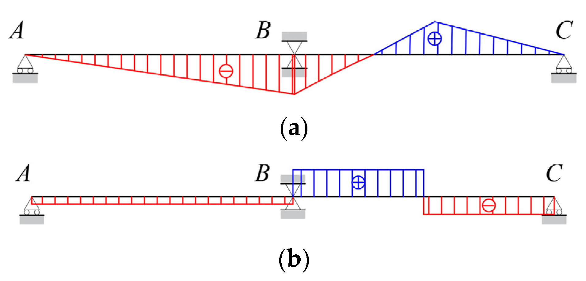
By solving the differential equations according to the initial parameter method, the forces at the rod end of the single span bars can be obtained. That is, the coefficients and the free terms in the equations of the displacement method can be used to solve the basic equations of the displacement method. After that, according to the superposition principle, the distribution of the non-uniform torsional internal forces of the two-span continuous beam, shown in Figure 5, under the concentrated torque in a span, can be identified. Figure 6 is the schematic diagram of the distribution of internal forces.

2.3. Effect of Crossbeams on Torsional Effects

When considering the crossbeam of the twin I-girder bridge in Figure 1, Zhang et al. [23] proposed that the influence of the crossbeam on the calculation of the non-uniform torsion for such an open section can be handled by equating the stiffness of the crossbeam, as reflected in the torsion differential equation as shown below:
E 1 I ω φ 4 x G K + K d φ x = m T x
where Kd is the equivalent stiffness of the crossbeam, expressed as follows:
K d = Ω c 2 l c b 12 E I c F c l c 2 G F c + 14.4 E I c
and where Ωc is the difference in the principal sectoral coordinates between the ends of the crossbeam, lc is the length of the crossbeam, b is the crossbeam spacing, and Ic and Fc are, respectively, the weak axis moment of inertia and the cross-sectional area of the crossbeam.
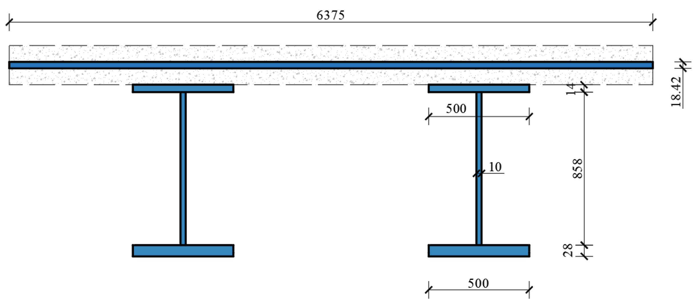
Referring to Equation (8), when the crossbeam is taken into account, the open section non-uniform torsion differential equation takes the same form as it would without it, except that its uniform torsional stiffness is increased. After calculation, one can find the following values K = 5.32 × 108 mm4, Kd = 2.51 × 106 mm4 for the twin I-girder bridge presented in Figure 1. Added to that, concerning the twin I-girder bridge, Kd is generally smaller with respect to K. Therefore, for analytical simplicity, the effect of the crossbeam on the overall torsional stiffness of the structure can be ignored.
The application of the above method is illustrated by the example of a two-span continuous girder. Each span of the bridge is 18.5 m long, with an effective span diameter of 18 m and the cross-sectional dimensions shown in Figure 1. The steel girders are made of Q345 steel, and the deck slab is made of C50 concrete. It is possible to calculate the principal sectoral moment of inertia of the section Iw = 6.93 × 10 mm16, the uniform torsional moment of inertia K = 5.32 × 108 mm4, and the equivalent stiffness of the crossbeam Kd = 2.51 × 106 mm4. A concentrated torque of T = 6.7 × 10⁸ N·mm is applied in the second span.
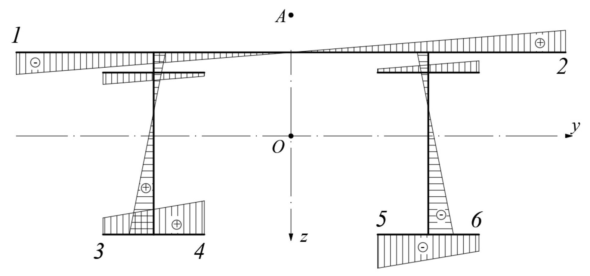
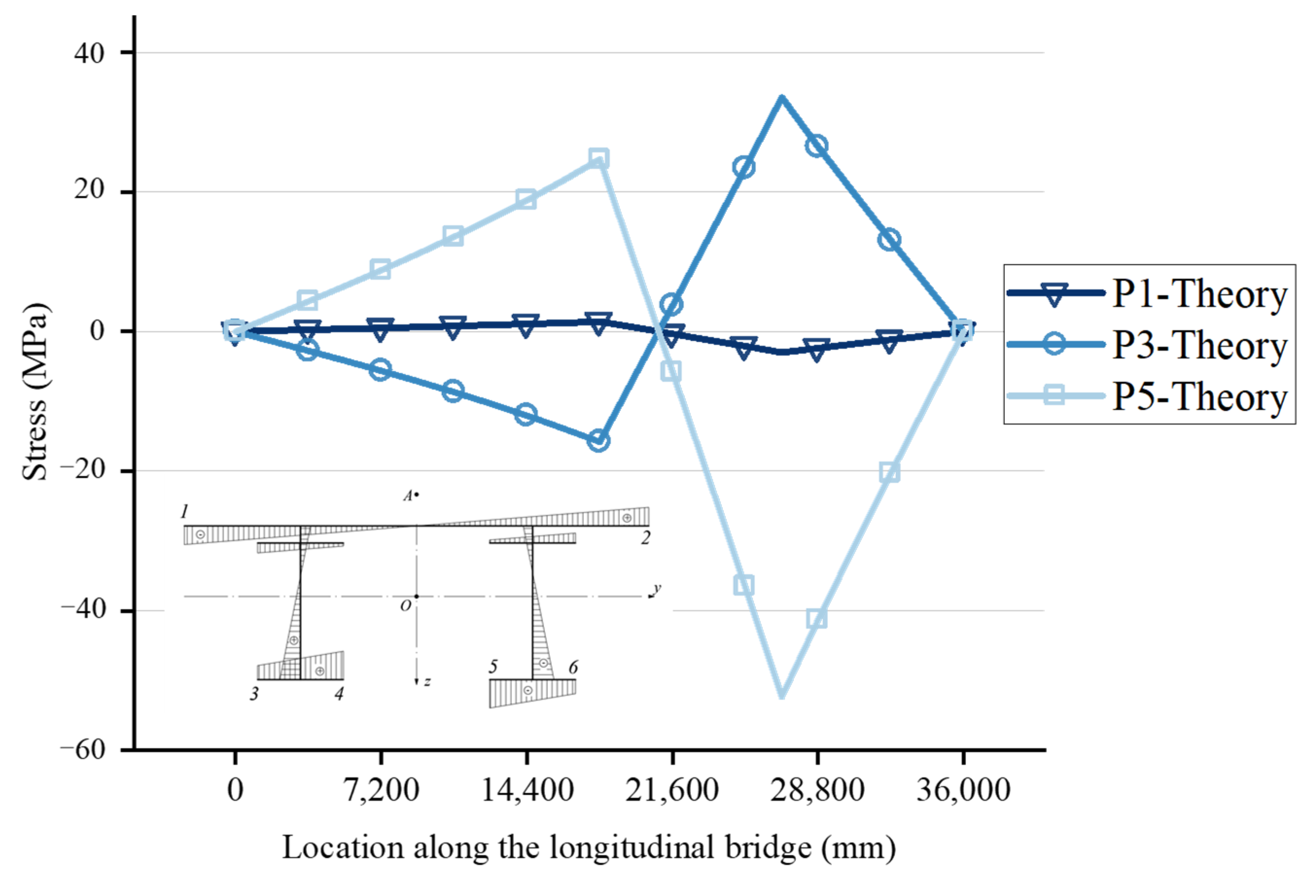
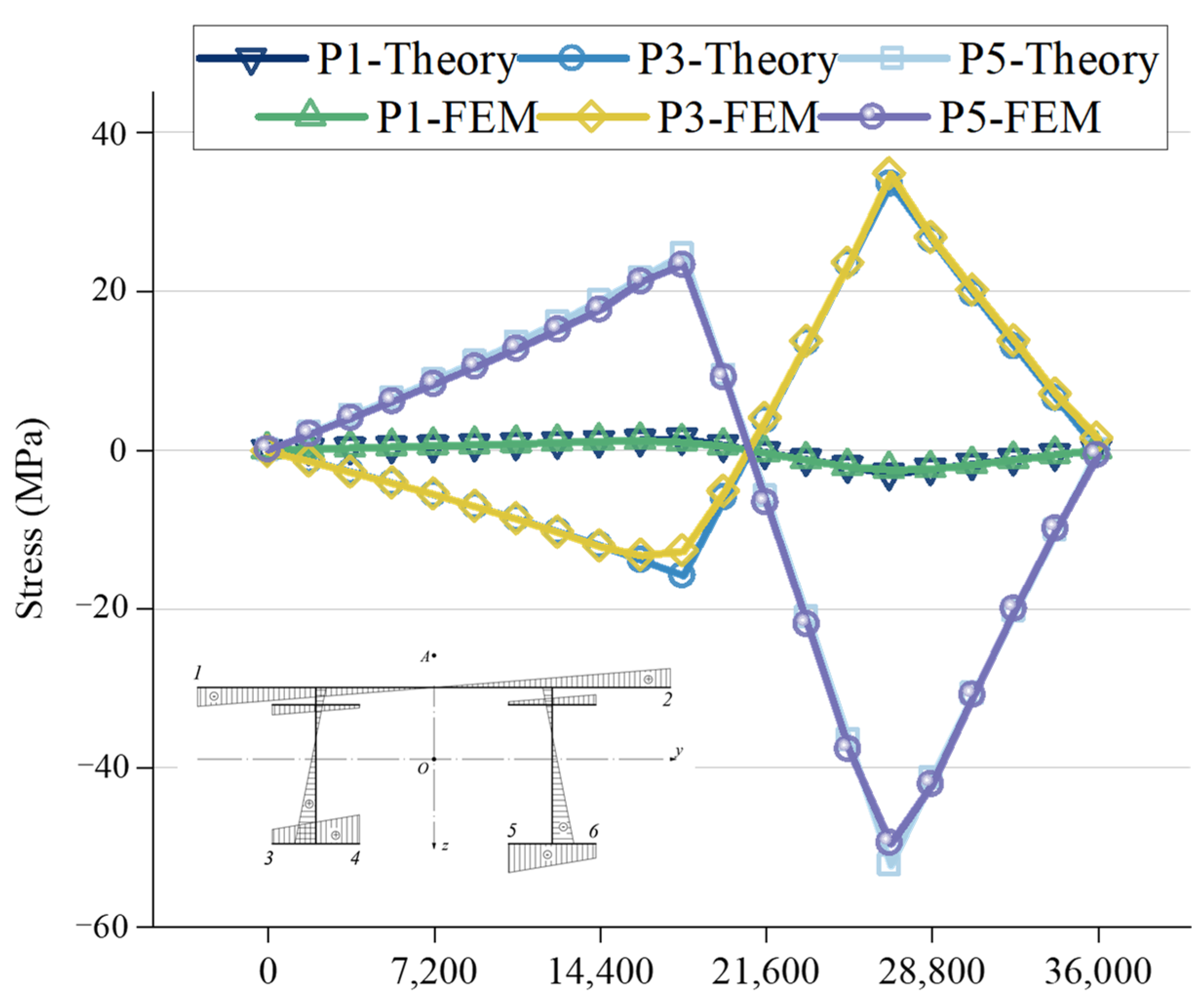
After obtaining the distribution of the bimoment B along the length of the beam, the stresses at each point of the section can be obtained according to the formula σ ω =   B I ω ω ( s ) . Referring to this formula, it can be found that for a definite section, the warping normal stress is proportional to the principal sectoral coordinate ω. Figure 7 shows the distribution of the principal sectoral coordinate of the section where point A is the shear centre of the section. The characteristic points are sorted, considering their distribution characteristics and the symmetry of the section. As for Figure 8, it only shows the calculation results of the warping normal stress for characteristic points 1, 3, and 5 (P1, P3, and P5).

3. Method of Calculating Internal Forces in Crossbeams

3.1. Crossbeam Internal Forces and Deformations

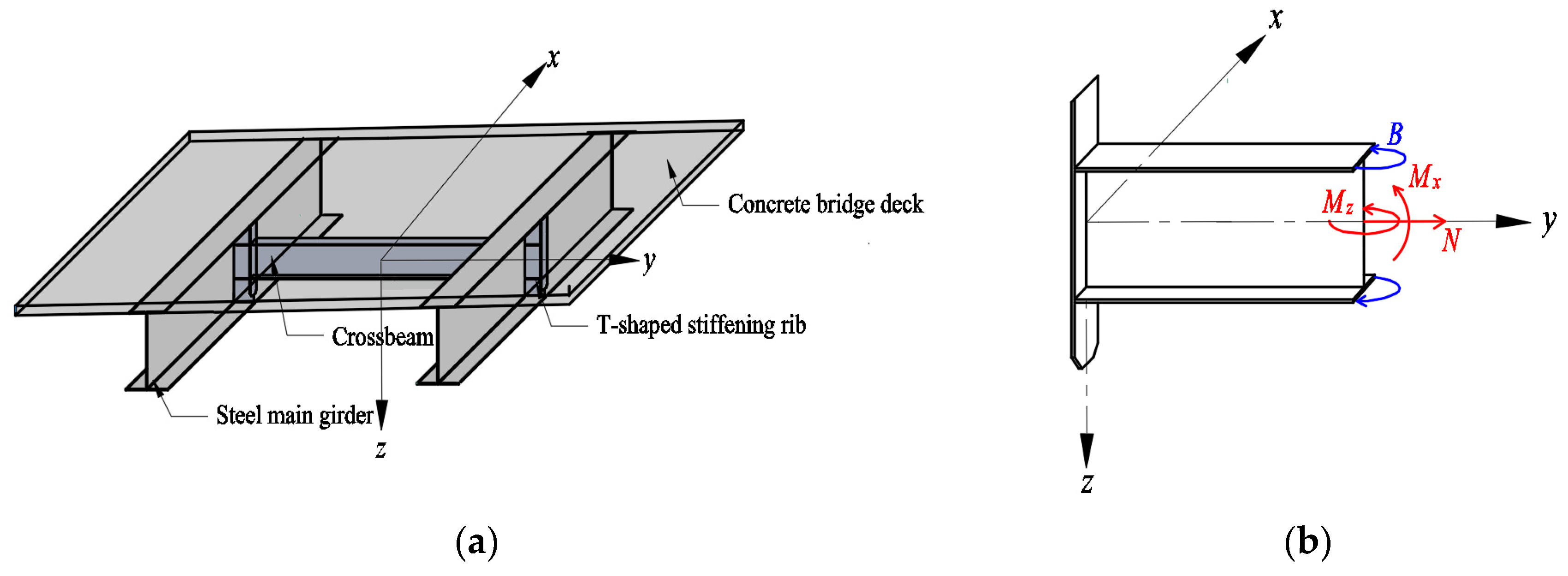
The crossbeam, acting as a bar supported between the webs of the main beam, has the cross-sectional internal forces shown in Figure 9, where Mx and Mz represent, respectively, the bending moments around the strong and weak axes of the I-beam, N represents the axial forces, and B represents the bimoment. Mx is the vertical moment of the crossbeam, and Mz is the longitudinal bridge moment of the crossbeam.
When lateral horizontal loads are applied to the crossbeam frame, it is subjected to vertical bending moments Mx and axial forces N, where Mx and N can be calculated from existing frame models [10]. Due to the coordinated deformation of the crossbeam and the web of the main beam, when the longitudinal bridge warping deformation of the main beam is considered, the crossbeam in the frame model is subjected to longitudinal bridge deformation, including longitudinal bridge bending and torsional deformation, and the crossbeam section is also subjected to longitudinal bridge bending moment Mz and bimoment B. Thus, this paper focuses on the accurate calculation of Mz and B.

3.2. Calculation of Internal Forces in the Frame Model Considering Warp Deformation of the Main Beam

Due to torsional loading, the web of the steel main beam produces opposite longitudinal bridge direction deformations Lw and opposite angles βw as presented in Figure 10, where the red dashed line represents the longitudinal bridge direction deformation of the main beam, the blue dashed line represents the longitudinal bridge position change of the T-stiffened ribs, and the solid blue line represents the longitudinal bridge position change of the crossbeam. Concerning Figure 10d, the deformation of the upper, central, and lower flange of the crossbeam section, along the longitudinal bridge direction, are U1, U2, and U3, respectively; thus, the deformation of the crossbeam can be modelled into longitudinal bridge direction deformation and torsional deformation. Assuming that the main beam web and the crossbeam deformations are coordinated, the longitudinal and the torsional deformations of the crossbeam can be expressed in terms of Lw and βw as follows:
L ω = U 2 β ω = ( U 3 U 1 ) h f

3.2.1. Internal Forces in the Crossbeam due to Longitudinal Bridge Deformation Lw

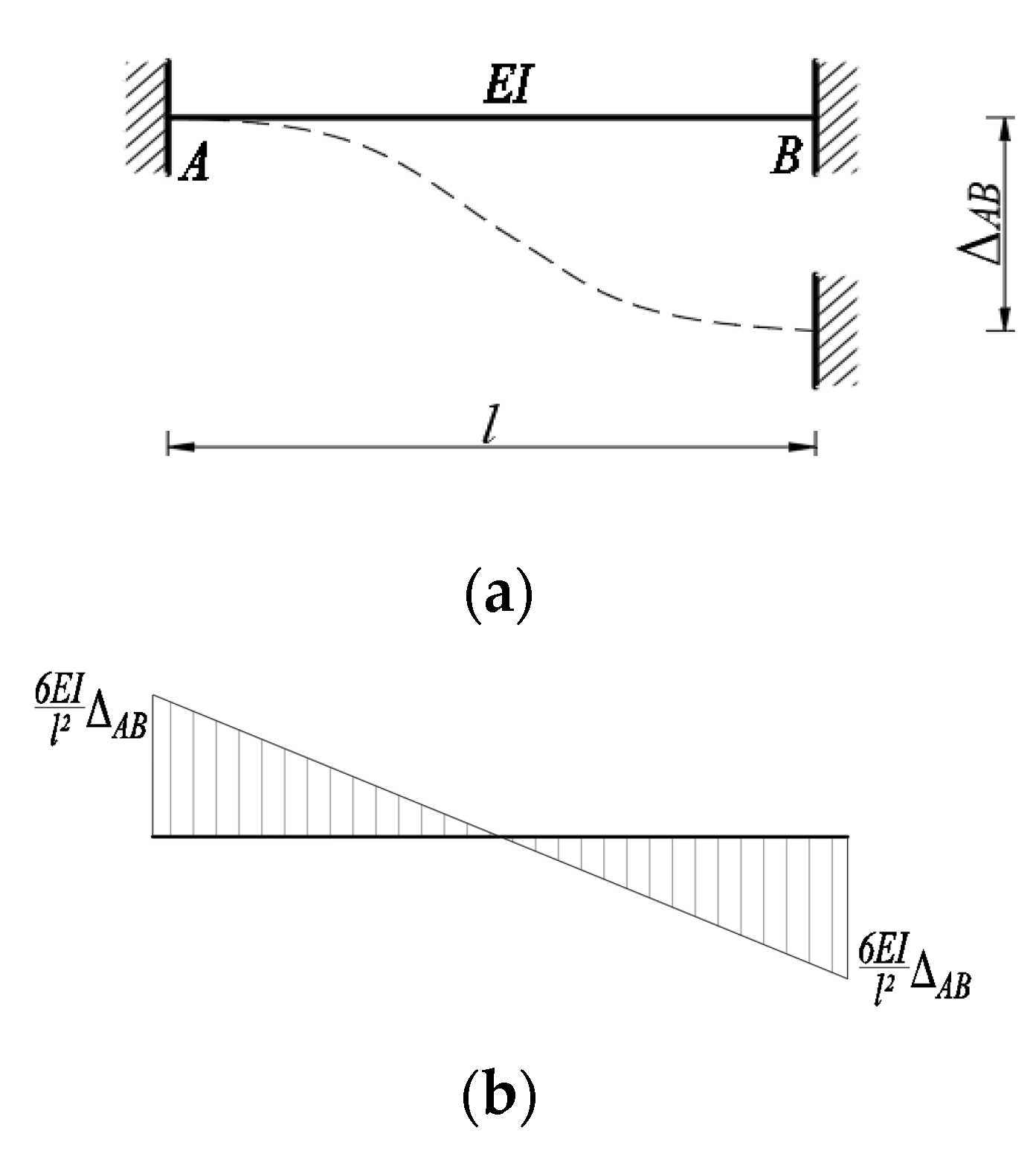
According to Figure 7 and to the equations yielding to calculate the warping displacement of the section, the relative displacement of the web of the G1 (Girder 1) and the G2 (Girder 2) is double Lw. Due to the welding relationship between the crossbeam and the T-shaped stiffening ribs, the crossbeam can be simplified to a bar solidified at both ends as shown in Figure 11. As Δ A B = 2 L ω , the bending moment expressions resulting from the longitudinal bridge deformation of the crossbeam are listed below:
M z = 6 E I c l c 2 2 L ω
where Mz is the longitudinal bridge bending moment.

3.2.2. Internal Forces in the Crossbeam Due to Torsional Angle βw

Similarly, the relative angle of rotation of the G1 and G2 webs is double the value of βw; thus, as in the case of the longitudinal bridge deformation, the crossbeam can be simplified to a bar solidified at both ends as shown in Figure 12 where Δ ϕ = 2 β ω . The expression for the internal forces of the crossbeam is as follows [10]:
B = 2 E I ω c l c 2 k 2 2 t h k 2 k 2 t h k 2 2 β w
where Iwc is the principal sectorial inertia moment of the crossbeam; k is a characteristic of the stiffness of the crossbeam in uniform torsion GKc relative to the stiffness in non-uniform torsion EIwc, expressed as follows:
k = l c G K c E I ω c
To sum up, the normal stresses, resulting from longitudinal bending and torsion of the crossbeam, due to longitudinal bridge deformation of the main beam, can be expressed as:
σ = M z W z c + B I ω c ω c s

4. Finite Element Verification of Torsional Performance for Continuous Beams

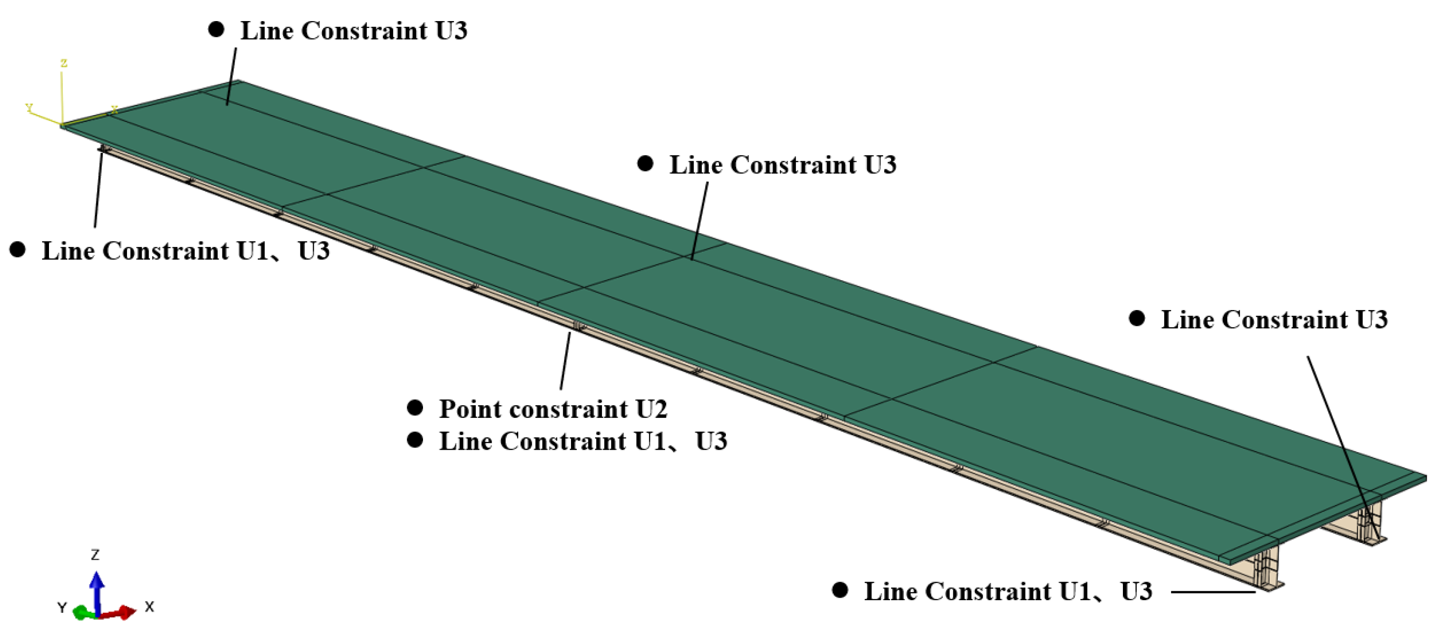
To verify the distribution of the warping normal stresses along the length of the beam, as shown in Figure 8, ABAQUS software was used for modelling and analysis. The bridge deck and the steel main girder were modelled using C3D8R solid units in the finite element modelling. The deck and the steel girder are in Tie bound contact and the slip of the deck is ignored. A web stiffening rib is set at 1.8 m intervals in the main girder to prevent structural distortion and to satisfy the assumption which considers that the section profile lines remain constant. The boundary conditions of this system are shown in Figure 13. Constraints U1, U2, and U3 refer to the longitudinal, transverse, and vertical constraints, respectively. To obtain a more intuitive pattern of stress distribution in the crossbeams, the end crossbeams are controlled to have the same size as the centre crossbeam. As shown in Figure 14, the crossbeams are numbered from left to right (crossbeams 1 to 11#).
Figure 15 shows a comparison of the warping normal stress results calculated using the theoretical formulas and the finite elements. It can be found that the theoretical solution is in total agreement with the finite element solution; however, only slight errors at the loading point section and at the centre support section are encountered. It can be seen that Vlasov’s theory can be applied to the non-uniform torsion analysis of the steel–concrete composite twin I-girder bridge.

5. Verification of the Crossbeam Internal Force Calculation Formula

5.1. Extraction of Internal Force Results for Crossbeams

Two sections were selected for each crossbeam, being 300 mm far from the T-stiffening ribs on both sides of the crossbeam. The stresses were extracted from four nodes in each section, and the nodes were located and numbered as shown in Figure 16.
The total stresses, coupled by all influences, are represented by the normal stresses in the crossbeam section retrieved from the finite element model as shown in Figure 17. Therefore, the stress values of the crossbeam are resolved to obtain the stresses σt from the tensile deformation, σw from the non-uniform torsional deformation, σMx from the vertical bending deformation, and σMz from the longitudinal bridge bending deformation shown in Equations (15), (16), and (18), respectively.
σ t = σ U 1 + σ U 2 + σ B 1 + σ B 2 4
where σ U 1 , σ U 2 , σ B 1 , and σ B 2 represent the finite element stress values of the corresponding points in Figure 16.
σ w = σ B 2 ( U 2 ) + σ U 1 ( B 1 ) 2
where
σ U 1 = σ U 1 σ t ; σ U 2 = σ U 2 σ t σ B 1 = σ B 1 σ t ; σ B 2 = σ B 2 σ t
where
σ M x = σ B 2 ( U 2 ) + σ B 1 ( U 1 ) 2 σ M z = σ B 2 ( U 2 ) σ B 1 ( U 1 ) 2
where
σ U 1 = σ U 1 σ ω ; σ U 2 = σ U 2 σ ω σ B 1 = σ B 1 σ ω ; σ B 2 = σ B 2 σ ω

5.2. Verification of Crossbeam Internal Force Results

Figure 18 shows the comparison between the equations’ outputs and the finite element results for the normal stresses generated by bending and the torsion of the crossbeam in the longitudinal direction. It can be found that the theoretical results and the finite element have the same behaviour as shown in Figure 18a,b; thus, it can be concluded that the theoretical development proposed in the article for the calculation of the internal force of the crossbeam is correct.
As the longitudinal bridge deformation of the crossbeam is related to the warping deformation of the main girder, which is proportional to the torsion angle rate, a curve of the stresses in the crossbeam along the length of the beam is fitted in Figure 18. Based on this output, one can find that the curve is consistent with the variation of the torsion angle rate of the main girder in Figure 19.

6. Conclusions

Based on the different results obtained in this work, the following conclusions can be made:
  • The torsional performance of the continuous steel–concrete composite twin I-girder bridge can be analysed according to Vlasov’s theory, as verified by the finite element analysis results;
  • The bending effects and torsional effects in the longitudinal direction of the crossbeam can be approximately obtained by calculating the warping deformation of the main beam at the same position;
  • The internal force calculation formulae in this paper are calculated by simplifying the crossbeam to a bar with two solid ends. For general loading effects (including torsion load and some lateral loads), the internal forces of the crossbeam can be obtained by adding the formulae proposed in this paper to the existing research.

Author Contributions

Conceptualization, J.L. and Y.L.; methodology, J.L.; software, L.C.; validation, J.L., Z.X. and B.F.; formal analysis, B.F.; investigation, Z.X.; resources, L.J.; data curation, L.C.; writing—original draft preparation, Z.X.; writing—review and editing, J.L.; visualization, L.J.; supervision, Y.L.; project administration, L.J.; funding acquisition, Y.L. All authors have read and agreed to the published version of the manuscript.

Funding

This research was funded by the Special Fund for Basic Scientific Research of Central College (Grant No. 300102219310) and the Science and Technology Project of the Department of Transport of Shaanxi Province (Grant No. 17-14k).

Institutional Review Board Statement

Not applicable.

Informed Consent Statement

Not applicable.

Data Availability Statement

Not applicable.

Conflicts of Interest

The authors declare no conflict of interest.

References

  1. Zhou, W.; Jiang, L.; Kang, J.; Bao, M. Distortional buckling analysis of steel-concrete composite girders in gegative moment area. Math. Probl. Eng. 2014, 2014, 635617. [Google Scholar] [CrossRef]
  2. Zhao, R.; Liu, Y.; Jiang, L.; Feng, B.; Fu, Y.; Zhang, C. Experimental study on hot spot stresses of curved composite twin-girder bridges. Materials 2022, 15, 7920. [Google Scholar] [CrossRef] [PubMed]
  3. Ma, H.; Shi, X.; Zhang, Y. Long-Term behaviour of precast concrete deck using longitudinal prestressed tendons in composite I-girder bridges. Appl. Sci. 2018, 8, 2598. [Google Scholar] [CrossRef]
  4. Park, S. Cross-Frame Stiffness Modification Factors for Composite Steel I-Girder Bridges; The University of Texas at Austin: Austin, TX, USA, 2021. [Google Scholar]
  5. Park, Y.; Hwang, S.; Hwang, M.; Choi, B.H. Inelastic buckling of torsionally braced I-girders under uniform bending: I. Numerical parametric studies. J. Constr. Steel Res. 2010, 66, 304–316. [Google Scholar] [CrossRef]
  6. Nguyen, C.T.; Moon, J.; Le, V.N.; Lee, H. Lateral–torsional buckling of I-girders with discrete torsional bracings. J. Constr. Steel Res. 2010, 66, 170–177. [Google Scholar] [CrossRef]
  7. Davidson, J.S.; Keller, M.A.; Yoo, C.H. Cross-Frame Spacing and Parametric Effects in Horizontally Curved I-Girder Bridges. J. Struct. Eng. 1996, 122, 1089–1096. [Google Scholar] [CrossRef]
  8. Sharafbayani, M.; Linzell, D.G. Optimizing horizontally curved, steel bridge, cross-frame arrangements to enhance construction performance. J. Bridge Eng. 2014, 19, 4014021. [Google Scholar] [CrossRef]
  9. Battistini, A.D.; Donahue, S.; Wang, W.H.; Helwig, T.A.; Engelhardt, M.D.; Frank, K.H. Brace stiffness and forces of X-type, K-type, and Z-type cross frames in steel I-girder bridge systems. In Proceedings of the Structural Stability Research Council/North American Steel Construction Conference, St. Louis, MO, USA, 16 April 2013; p. 2013. [Google Scholar]
  10. Lebet, J.P.; Hirt, M.A. Conceptual and Structural Design of Steel and Steel-Concrete Composite Bridges; EFPL Press: Lausanne, Switzerland, 2013. [Google Scholar]
  11. Poellot, W.N. Computer-aided-design of horizontally curved girders by the v-load method engineering journal. Am. Inst. Steel Constr. 1987, 24, 42–50. [Google Scholar]
  12. Liu, D.; Magliola, R. End forces on crossframes in horizontally curved steel I-girder bridges. Pract. Period. Struct. Des. Constr. 2010, 15, 21–26. [Google Scholar] [CrossRef]
  13. Gaylord, E.H.; Gaylord, C.N.; Stallmeyer, J.E. Structural Engineering Handbook; McGraw-Hill: New York, NY, USA, 1997. [Google Scholar]
  14. Grubb, M.A. Horizontally curved I-girder bridge analysis: V-load method. Transport. Res. Rec. 1984, 982, 26–36. [Google Scholar]
  15. Xing, Z. Study on the Stress Mechanism of the Cross Beam of the Curved Twin I-Girder Composite Bridge; Chang’an University: Xi’an, China, 2022. (In Chinese) [Google Scholar]
  16. Yan, X.; Liu, Y.; Xing, Z.; Feng, B.; Chen, X. Research on internal force of crossbeam in curved steel-concrete composite twin I-girder bridge. J. Archit. Civ. Eng. 2022, 39, 63–73. (In Chinese) [Google Scholar]
  17. Xiang, D.; Liu, Y.; Yang, F. Numerical and theoretical analysis of slab transverse-moment distributions in twin-girder crossbeam composite bridges. J. Bridge Eng. 2020, 25, 4020004. [Google Scholar] [CrossRef]
  18. Chen, X.; Zhou, W.; Kong, L. Study on slip effects of simply-supported composite beams. In IOP Conference Series: Earth and Environmental Science; Iop Publishing: Bristol, UK, 2019; p. 32041. [Google Scholar]
  19. Nie, J.; Cai, C.S. Steel–concrete composite beams considering shear slip effects. J. Struct. Eng. 2003, 129, 495–506. [Google Scholar] [CrossRef]
  20. Nie, J.G.; Cai, C.S.; Zhou, T.R.; Li, Y. Experimental and analytical study of prestressed steel–concrete composite beams considering slip effect. J. Struct. Eng. 2007, 133, 530–540. [Google Scholar] [CrossRef]
  21. Kollbrunner, C.F.; Basler, K. Torsion in Structures: An Engineering Approach; Springer Science & Business Media: Berlin, Germany, 2013. [Google Scholar]
  22. Vlasov, V.Z.; Schechtman, Y. Thin-Walled Elastic Beams; Israel Program for Sciemtific Trnsiacionss Ltd.: Jerusalem, Israel, 1987. [Google Scholar]
  23. Zhang, Y.; Hou, Z.; Li, Y.; Wang, Y. Torsional behaviour of curved composite beams in construction stage and diaphragm effects. J. Constr. Steel Res. 2015, 108, 1–10. [Google Scholar] [CrossRef]
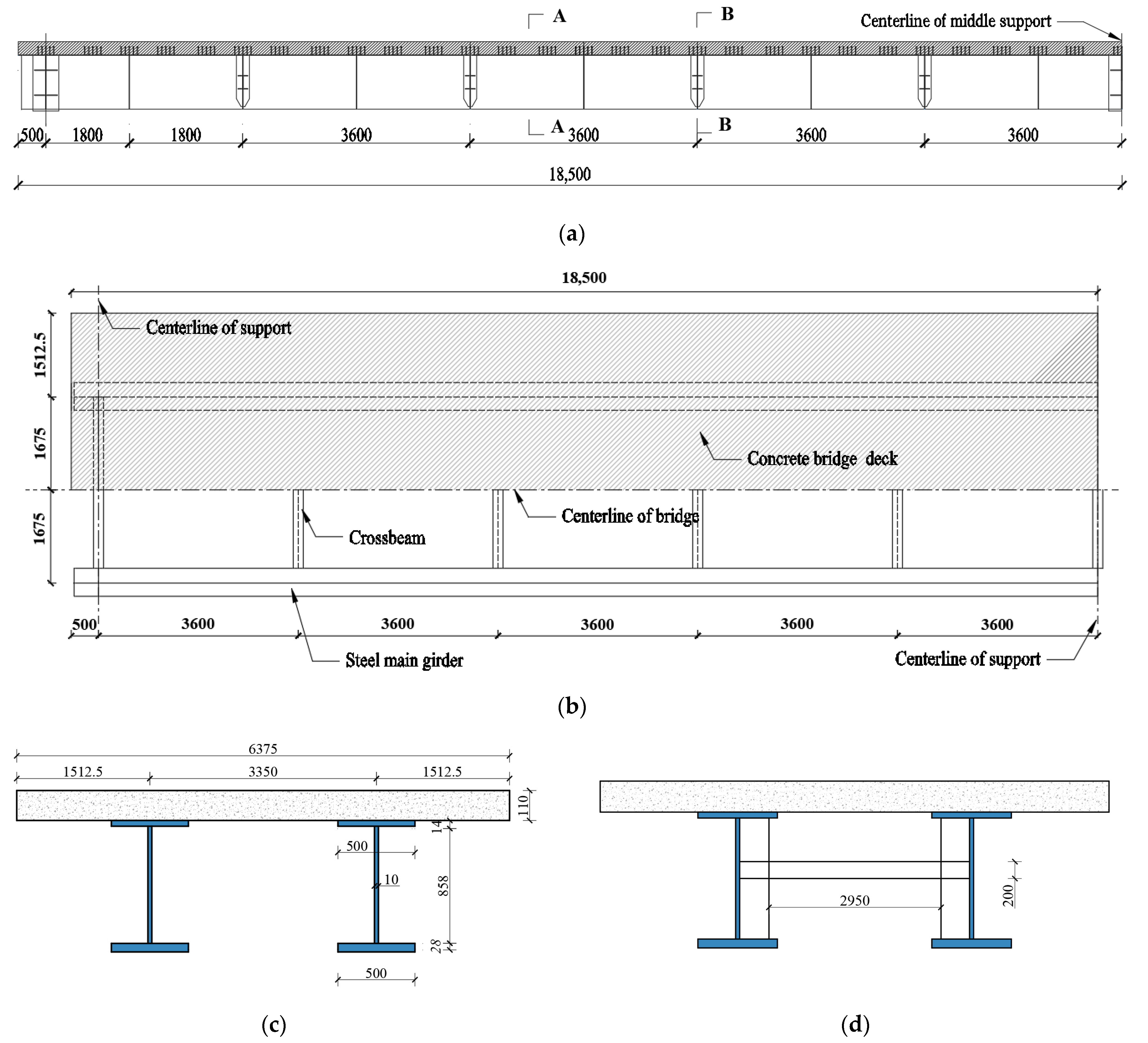
Figure 1. Twin I-girder bridge (in mm): (a) Elevation view (first span, two spans in total); (b) Bird’s-eye view (first span, two spans in total); (c) Plane view (Section A-A); (d) Plane view (Section B-B).
Applsci 13 06669 g001
Figure 2. Equivalent cross-section.
Applsci 13 06669 g002
Figure 3. Planar rigid frame: (a) force diagram (b) basic system.
Applsci 13 06669 g003
Figure 4. n-span twin I-girder continuous bridge.
Applsci 13 06669 g004
Figure 5. Two-span twin I-girder continuous bridge with concentrated torque acting in a single span.
Applsci 13 06669 g005
Figure 6. Schematic diagram of the distribution of internal forces: (a) Bimoment B along the length of the beam (b) Torsional moment T along the length of the beam.
Applsci 13 06669 g006
Figure 7. Distribution of principal sectoral coordinates w and ordering of feature points.
Applsci 13 06669 g007
Figure 8. Distribution of warping normal stress along the length of the beam.
Applsci 13 06669 g008
Figure 9. (a) 3D schematic (b) internal forces in crossbeam.
Applsci 13 06669 g009
Figure 10. Out-of-plane deformation of the crossbeam due to warping of the main beam: (a) longitudinal bridge deformation of the main beam due to torsion; (b) deformation of the T-rib driven by the web of beam 1; (c) deformation of the T-rib driven by the web of beam 2 and (d) longitudinal bridge deformation of the crossbeam.
Applsci 13 06669 g010
Figure 11. Calculation of the internal forces in the longitudinal direction of deformation of the crossbeam: (a) simplified calculation model, and (b) bending moment diagram.
Applsci 13 06669 g011
Figure 12. Simplified calculation model.
Applsci 13 06669 g012
Figure 13. Boundary conditions.
Applsci 13 06669 g013
Figure 14. Crossbeam number.
Applsci 13 06669 g014
Figure 15. Comparison of the results of the main girder warping normal stress.
Applsci 13 06669 g015
Figure 16. Location and number of result extraction points.
Applsci 13 06669 g016
Figure 17. Normal stresses in the section of the crossbeam.
Applsci 13 06669 g017
Figure 18. Comparison between the theoretical results and finite element results: (a) Normal stresses due to longitudinal bridge bending of the crossbeam and (b) Normal stresses due to torsion of the crossbeam.
Applsci 13 06669 g018
Figure 19. Main beam torsional angular rate distribution.
Applsci 13 06669 g019
Table 1. Sketch of the calculation of single span statically indeterminate bars.
Load FormFixed at One End and Hinged
at the Other
Fixed at Both Ends
Concentrated torqueApplsci 13 06669 i001Applsci 13 06669 i002
Uniform torqueApplsci 13 06669 i003Applsci 13 06669 i004
Unit warping deformationApplsci 13 06669 i005Applsci 13 06669 i006
Disclaimer/Publisher’s Note: The statements, opinions and data contained in all publications are solely those of the individual author(s) and contributor(s) and not of MDPI and/or the editor(s). MDPI and/or the editor(s) disclaim responsibility for any injury to people or property resulting from any ideas, methods, instructions or products referred to in the content.