Article

Case Study on the Effect of Delay-Time Differences between Columns during Blasting Demolition of RC Structures with a Small Height-to-Width Ratio

1
College of Civil Engineering and Architecture, Shandong University of Science and Technology, Qingdao 266590, China
2
The Second Construction Limited Company of China Construction Eighth Engineering Division, Jinan 250014, China
*
Author to whom correspondence should be addressed.
Appl. Sci. 2023, 13(11), 6765; https://doi.org/10.3390/app13116765
Submission received: 25 April 2023 / Revised: 21 May 2023 / Accepted: 31 May 2023 / Published: 2 June 2023
(This article belongs to the Section Civil Engineering)

Abstract

:
Blasting demolition plays an important role in building demolition, and numerical-simulation methods can facilitate the optimization of blasting-demolition schemes. To study the influence of the delay-time differences between columns on the blasting and demolition effect of small-aspect-ratio reinforced concrete structures, a separated common node model of small-aspect-ratio structures was established through the finite element numerical simulation software ANSYS/LS-DYNA. The results showed that the delay-time differences between columns influenced the position of the plastic hinge of the structure, and the plastic hinge was located at the end of the back span beam when the delay-time difference was 0.1~0.3 s. The plastic hinge moves to the top of the back row of the columns of the first floor at 0.4~0.8 s and to the end of each span of the beams at 0.9 s. When the plastic hinge is at the end of the beam, the orientation axis is located at the bottom of the back row of the columns of the first floor. Moreover, when the plastic hinge is at the top of the back row of the columns of the first floor, the orientation axis is at the same position as the plastic hinge. The delay-time difference also affects the recoil distance of the structure as well as the height of the burst pile. To ensure that the structure can be successfully collapsed under the preconditions of disintegration, for a small height-to-width ratio structure, the appropriate intercolumn delay-time difference is 0.4~0.5 s.

1. Introduction

In recent years, many buildings that have reached the end of their useful life need to be demolished to meet the requirements of urbanization [1]. Demolition by blasting is advantageous because this process is safe and efficient; moreover, blasting demolition is regarded as a very important technique in the demolition of buildings (structures) [2]. Through many engineering practices, the collapse effect of building-structure demolition and blasting is greatly affected by the time differences between column extensions. In this paper, we take the blasting and demolition of a small-aspect-ratio reinforced concrete structure in a workshop as the engineering background, use ANSYS/LS-DYNA (19.0) software to establish the finite element model of the structure, conduct numerical simulation and theoretical analysis of the demolition and blasting effect of the structure, and investigate the influence of the delay-time differences between the columns on the blasting-collapse effect of the small-aspect-ratio reinforced concrete structure by changing the delay-time differences between columns while maintaining the other settings as unchanged.
With the increase in urban old building reconstruction and the demolition and reconstruction of plant-type projects, the requirements for demolition and blasting technology are also increasing, and unreasonable demolition and blasting schemes can threaten the personal safety of construction personnel [3]. Currently, most demolition and blasting work is still based on engineering experience [4], and demolition theory is lagging; thus, increasing the theoretical research on demolition and blasting is currently the most urgent problem [5] Bazant and Verdure analyzed and studied the mechanical characteristics of the progressive collapse of high-rise buildings by analyzing the continuous collapse process. A dynamic one-dimensional continuous model suitable for structural collapse was proposed. The collapse response of buildings was studied with the energy method, and the relevant parameters of the progressive collapse of structures were calculated [6]. Jinshan Sun et al. studied the stress–strain characteristics of RC columns during blasting and the failure mode of concrete and proposed a transient conceptual model that can describe the stress state of columns during blasting. After the explosion, the bearing capacity of the column gradually decreases to less than the initial axial compressive stress, and then the initial stress is linearly released to zero. After the failure of concrete, the longitudinal reinforcement bends and produces strong tensile stress in the residual column, and its stress-time-history curve is triangular [7]. Sijie Wang and Min Gong, based on an 84 m frame core tube shear wall structure, analyzed the collapse process of the structure, which lost its bearing capacity due to the destruction of strength and stiffness, obtained the average stress and maximum stress of the reserved column after the structure was impacted by blasting, and explored the influence of delay-time difference on the collapse effect of the building. It was pointed out that by selecting an appropriate delay-time difference, the reserved column can bear large average stress and effectively prevent recoil [8]. Isobe Daigoro and Jiang Ranmeng put forward a key element index for estimating the contribution of columns to the bearing capacity of structures by applying vertical loads to each beam–column node of buildings and conducting static analysis on undamaged buildings. The purpose of the first blasting of the bearing column is not to destroy the building but to reduce the strength of the column as much as possible for the main explosion. In the process of blasting, the collision between structures should be made full use of to destabilize the structure and maximize the impact effect. It was proposed to use key element indexes to help engineers semi-automatically set the time difference between the blasting column and the blasting delay [9]. Yongsheng Jia et al. proposed a method of folding and implosion of buildings with regular cross-sections, which formed several blasting gaps by segmenting the buildings. Transforming the building into a folded motion chain, it falls and overlaps with each other, collapsing and touching the ground. The design criteria of the main parameters of folding blasting were proposed, the multi-body dynamic models of two-way and three-way folding collapse were derived, and the early collapse process was predicted. Then, the design criteria and kinematic model were verified by the collapse process of two buildings [10]. With the development of computer science, numerical simulation technology has been widely used because of its high efficiency and economic advantages. It has become an irresistible trend to use computer simulation technology to study the collapse process of building blasting demolition [11,12]. Many scholars have carried out a lot of research by using numerical analysis methods, and more intuitively analyzed the collapse process of buildings and the stress state and velocity changes of various parts of the structure, which has made great contributions to the development of blasting demolition theory. After analyzing the stress state and deformation characteristics of concrete, longitudinal reinforcement, and stirrup in each stage, Haipeng Jia proposed a simplified model of reinforced concrete. This model can better reflect the softening characteristics and tensile stress truncation characteristics of concrete, and the numerical model is continuously modified through the axial compression experiment of concrete specimens. Applying this model to the numerical simulation of building collapse, it was found that the simulation effect has a high degree of fitting with the actual project [13]. Min Gyeongjo. performed numerical simulations by coupling the three-dimensional discrete element method with a reinforcement model for three-point bending tests of reinforced concrete beams, discussed the effect of concrete member dimensions on the fracture process of reinforced concrete beams, and compared the numerical simulation results of the collapse process of the structure with the actual test results and found that they were in good agreement [14]. Yan et al. conducted a numerical simulation of blast-vibration velocity in blasting construction, explored the distribution law of blast vibration on the slope surface and inside the slope, and verified the effectiveness of the LS-DYNA program by fitting the program with field monitoring data [15]. Zhai et al. analyzed the rupture mechanism and zoning characteristics of concrete walls under blasting action, studied the effects of stress waves and high-pressure gas expansion on the blast demolition process through a simulation using the finite element software LS/dyna to establish a blast demolition kinetic model, and determine the crushing zone caused by reflected stress waves in concrete and a radial fracture range according to the maximum tensile stress theory [16]. Chai et al. used finite element software to simulate and study the collapse motion law of ultra-high coaxial thin-walled steel inner cylinder reinforced concrete chimney (UCTS-RCC), successfully establishing the theoretical model of SIC cut-angle selection and overall synchronous tipping of UCTS-RCC, and then successfully demolished a UCTS-RCC building [17]. To study the mechanical properties of high-rise steel structures during collapse, Xiaoguang Zhou updated the Lagrangian algorithm by means of the momentum conservation equation and the imaginary work equation and simulated it using LS-DYNA (19.0) software. The experimental results showed that the updated algorithm can improve the similarity in the actual demolition work by 97%, which is a high reference value for the simulation of the demolition of high-rise steel structures [18].
The above research analyzed the influence of blasting parameters on the blasting effect, and theoretically studied the collapse mechanism and dynamic state of the structure but did not study the collapse process and characteristics of the structures in detail. Numerical simulations can provide a reasonable theoretical basis for blasting construction, and variables, such as incision location, blast height, and time intervals, can be specified on demand to simulate the collapse process of buildings (structures) and predict the blasting construction results. Taking into account the material inhomogeneity of the members, the specific location of the reinforcement in the structure, the relative slip of the reinforcement when the concrete fails, and a large number of reinforcement nodes in the structure, the separated co-node method can be used to model the building, dividing the units of reinforcement and concrete separately, controlling the bond-slip of concrete and reinforcement using the connection unit, computing the unit stiffness matrix of concrete and reinforcement separately, and then compounding them into one stiffness matrix. By the timely deleting of blasting elements and by optimizing parameters and selecting appropriate element materials, more reasonable simulation results can be obtained. By comparing the collapse effect of the structure under time differences of 0.1~0.9 s, the influence law of the time difference on the blasting effect of the structure can be analyzed, and the optimal postponement time difference can be determined.

2. Project Overview

A 34.4 m high acid-station workshop (Figure 1 shows the traffic location map) in a chemical fiber factory that is being relocated needs to be demolished. Moreover, the current plant facilities within 100 m around the acid-station workshop within the factory are to be demolished. The acid-station workshop is on the northwest side of the plant, which is 739 m east from Weixian North Road and 715 m south from Democracy Street. The north side of the plant, which is 450 m from Hanting-Shuang Yang Road, has been dismantled. Moreover, there are no other key objects that need protection within 300 m of the acid-station workshop to be demolished.
The structural properties are shown in Table 1. The acid-station workshop is a frame structure in which the height of the 1st floor is 9 m, the height of the 2nd floor is 7 m, the height of the 3rd floor is 4.6 m, and the height of the 4th floor is 12.8 m. The 8th pillar from east to west is a double pillar. The cross-sectional area of the column is 750 mm × 750 mm, and the cross-sectional area of the longitudinal beam is 800 mm × 500 mm. The total weight of the acid-station workshop is 11,470 t.
We comprehensively considered the environmental conditions surrounding the blasting object, and made full use of the excavation of shock absorption grooves and the stacking of buffer cushions to reduce structural ground vibration and fragmentation of flying stones, and to avoid the ground vibration caused by explosions affecting the stability of nearby buildings [19,20]. The horizontal collapse distance of the structure is approximately 0.7 to 1 times the height of the building to be demolished; its lateral collapse range can reach 2 to 2.5 times the outer width of the building. Adhering to the principle of “safety first”, it was determined that this small-aspect-ratio reinforced concrete structure should tumble in the due north direction, as shown in Figure 2. There are five rows in the north–south direction and twelve rows in the east–west direction of the building.
According to the blasting demolition regulations, the triangular notch can be selected for this blasting [21]. The top of the pillar of the reinforced concrete structure is rigidly connected to the superstructure, that is, the top of the pillar is not free to move vertically downward. Especially in the blasting moment of the pillar, the superstructure has a strong restrictive effect on the pillar. In some engineering projects, the destruction of the support column will occur obliquely but not fall. To ensure that the structure can be destabilized by the overall tipping, the angle of collapse of the demolition structure is used to calculate the maximum height of the blasting incision h. The empirical formula is:
h = B   × tan α
where h is the maximum height of the blast incision; B is the width of the building; and α is the collapse angle, generally taken as 25°~40°.
Regarding the workshop plant, B is 25 m, and α is 30°; thus, the height is calculated to be h = 14.4 m. This blast height is the maximum required blast height in the collapse direction. To create collapse space, the proposed step gap is coupled with the collapse direction of the outermost local area for drilling and blasting rigidity weakening. Thus, the blast gap height meets the requirements.
During the simulation process, the failed material *MAT_ADD_EROSION is used to delete the blasting cut unit at a certain moment, thereby achieving the effect of simulating delayed detonation. For the blasting results, the concrete material uses *MAT_PLASTIC_KINEMATIC and additional control option *MAT_ADD_EROSION to jointly control the material failure, and *MAT_PLASTIC_KINEMATIC is used to simulate the failure of steel bars. The detonation network is an important part of the demolition phase of blasting, and a reasonable blast-hole arrangement and extension time are also key to the safe conduct of the blasting design [22]. When implementing blasting and demolition in the plant, it should be ensured that the detonation network is accurately detonated according to the design of the blasting program. Moreover, the safety and accuracy of the detonation network is strictly required. The blasting program detonation networks comprise nonelectrical and two-way multipoint triggers of half-second detonators., In rows without segments, the time difference between the rows were half a second. The A, B, C, D, and E rows of the columns were loaded with on section, two sections, three sections, four sections, and five sections of half-second detonators. Then, one section of the tube was used for the connections. Finally, plastic detonators with four-way triggers will be connected between the columns of each connection point through a closed network.

3. Numerical Simulation Analysis of Demolition by Blasting

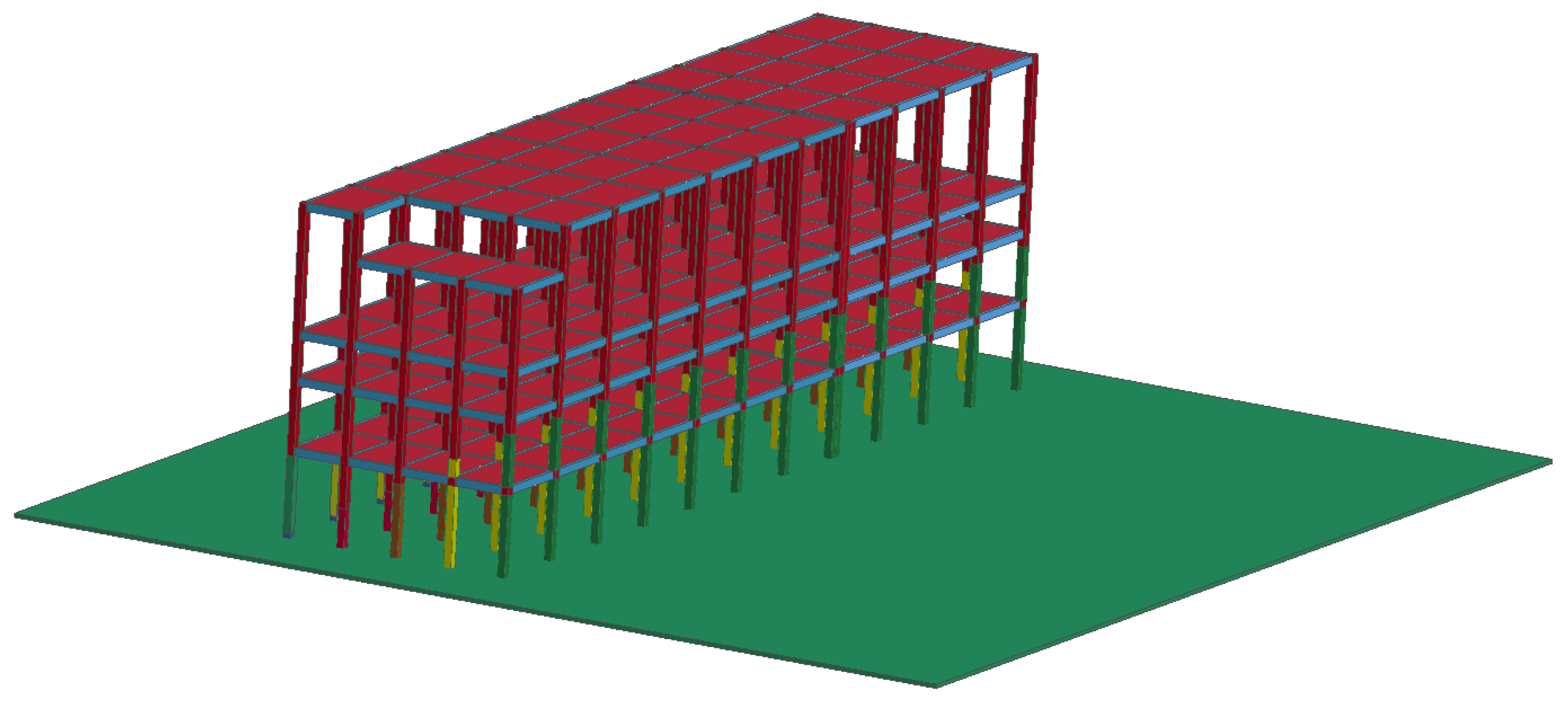
3.1. Structural Modeling Analysis

ANSYS/LS-DYNA is a dynamic display finite element analysis program with comprehensive functions for geometric materials and contact nonlinearity. It can handle nonlinear problems such as large deformation and displacement, as well as complex contact problems. In the numerical simulation, elements are directly deleted to form blasting notches, and explicit solutions are used to perform dynamic analysis of nonlinear problems. There is a difference in the force condition of the reinforcement and concrete during the damage of the compressed member, and the support column after the blast cut is fully formed and is shown as an example in Figure 3. The reinforcement units are arranged on both sides of the concrete columns and are connected to the concrete by means of common nodes. The vertical dimension of the concrete units is h.
In the normal working stage of the building, the support column is in the axial-compression state, and its specific force situation is shown in Figure 3a when the reinforcement and concrete are jointly subjected to the vertical load of the superstructure and both strains are the same. When the blast cut is fully formed and the structure touches the ground, the rear support column quickly enters the large eccentric-pressure state and is subject to the joint action of the axial force and bending moment. The force situation is shown in Figure 3b. In this process, the lower-left outer unit of the column will be the first to fail due to tension, but the reinforcement with its common node is still subject to tensile force. The neutral axis of the column moves forward so that the tension in the outer reinforcement is gradually increased until the reinforcement unit reaches the failure strength and collapses.
According to the shape and stress characteristics of beams, columns, floors, and reinforced components, appropriate element types are selected, and the corresponding material properties are given to them to form parts. For each blasting cut, a separate part is established to control its failure at a specific time. Then, the boundary conditions of the model are set, and the contact between the parts, the calculation time, and step size of the model are set, the file output type is set, and then the output of the K file is produced. By modifying the K file in the editor and adding the keyword of gravity, the solution and calculation can be obtained. The building blasting demolition numerical model establishment process is shown in Figure 4.
The reinforced concrete structure was modeled and analyzed with a small-aspect ratio of 1:1 according to the actual dimensions. Since the actual blasting process did not destroy the reinforcement at the blast incision, the reinforcement at the incision was weakened accordingly in the simulation to reduce its stiffness and increase its deformation capacity in addition to some pretreated reinforcement. ANSYS/LS-DYAN has a wide variety of elements, each with different algorithms, and can be used for all nonlinear options. Choosing the appropriate element can make the simulation results more accurate. The beam-column part of the structure is represented by the SOLID164 unit, the reinforcement is represented by the BEAM161 unit, and the rigid floor and slab are represented by the SHELL163 unit. The concrete structure model and the reinforcement structure model are shown in Figure 5 and Figure 6, respectively, and the unit size of this model is set to 0.2 m. During the modeling process, the role of the infill walls was not considered, and their weight and strength were equated to the structural floor slab. Moreover, the floor slab was represented by a monolithic model. Only the vertical and transverse reinforcement was created for the columns and beams, and the role of hoop reinforcement was not considered, so the strength of the concrete columns was properly adjusted. The protective layer thickness of the reinforcement was not considered and was only arranged on the outside of the concrete columns [23,24]. The physical and mechanical parameters of the reinforcing steel and concrete are shown in Table 2.

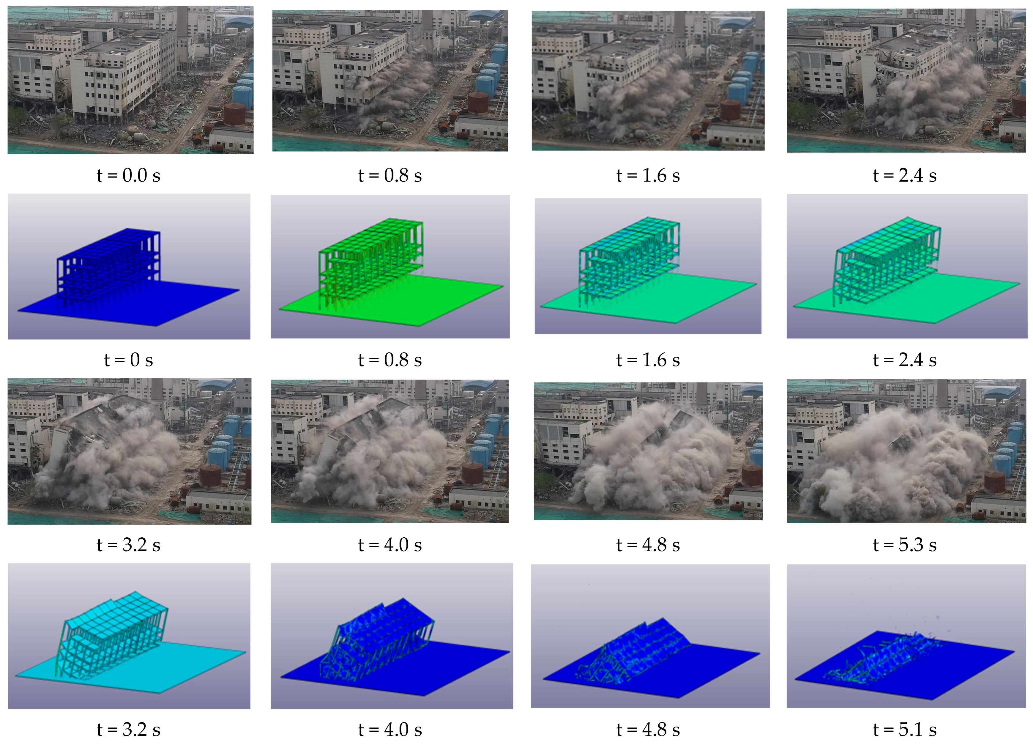
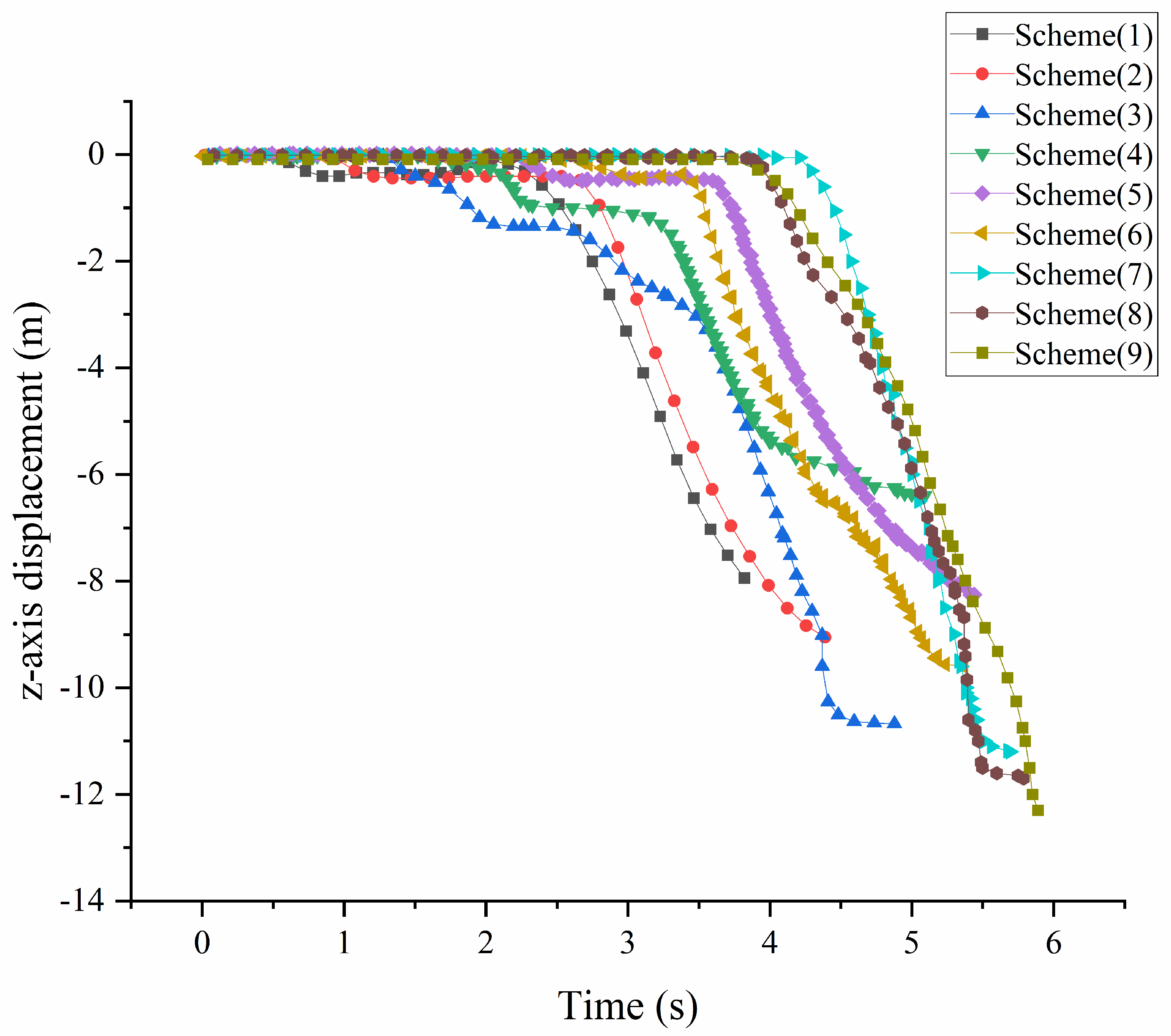
3.2. Collapse Process Comparison

The numerical simulation results were provided with 0.8 s intervals, and the delay-time difference of 0.5 s was outputted. The results were compared and analyzed. Moreover, photos of the collapse process were taken. Finally, the collapse was completed when the structure broke down and touched the ground. The comparison process is shown in Figure 7.
Figure 7 shows that the numerically simulated time-scale collapse attitude of the small-aspect-ratio reinforced concrete structure from 0 s to 5.1 s maintains a high degree of consistency with the actual collapse attitude. The difference is that the completion time of the disintegration in the numerical simulation is 5.1 s, while the actual collapse time of the building is 5.4 s, as shown by the video. Since these times are very similar, the results are satisfactory, thus indicating that the selected model can reflect the actual collapse of the structure realistically. The comparative analysis between the numerical simulation and actual video shows that the collapse process of this small-aspect-ratio structure can be divided into four stages: blast-incision formation (0.2~2.2 s), destabilization overturning (2.2~2.59 s), incision closure (2.59~4.2 s), and structure-touchdown disintegration (4.2~5.1 s).

3.3. Recoil Distance and Burst Stack Comparison

In the process of demolishing a building by blasting, the distance from which the rear supporting column of the building deflects to the rear and the distance from which the whole structure slides backward can be collectively referred to as the recoil distance. Figure 8 shows the small height-to-width ratio of the reinforced concrete structure of the actual burst pile and the numerical simulation of the burst pile comparison schematic diagram. As shown in the figure, the burst pile and numerical simulation results are similar to a trigonal shape. From the side analysis, the plant structure is composed of more beams and columns in a “box structure” because the impact of the explosion on the building structure of the damage process has a very large impact [25]. When the first and second rows of columns in the structure of the ground disintegration consume considerable deformation energy and kinetic energy, energy consumption in the third row of columns at the top of the process will be reduced, the plant structure will be changed from box-shaped to triangular, and finally, the burst pile forms into a trigonal shape.
The building collapsed toward the north. In the numerical simulation, the structure of the burst pile height and recoil distance were 7.6 m and 8.10 m, respectively, while the actual burst pile height was 8.3 m, and the recoil distance was 7.4 m. Thus, the numerical simulation and the actual blasting and demolition of the burst pile height and recoil distance deviated by 8.4% and 8.7%, respectively. This is because the structure of the beam column is relatively long. Moreover, the ground is set rigid. Thus, the beam column composed of the “box structure” deformation capacity is also stronger, resulting in a more complete degree of structural collapse and disintegration. Additionally, the burst stack height is low, and the recoil distance is large. However, the error is within the allowable range of the numerical simulation, and the simulation results are relatively satisfactory.

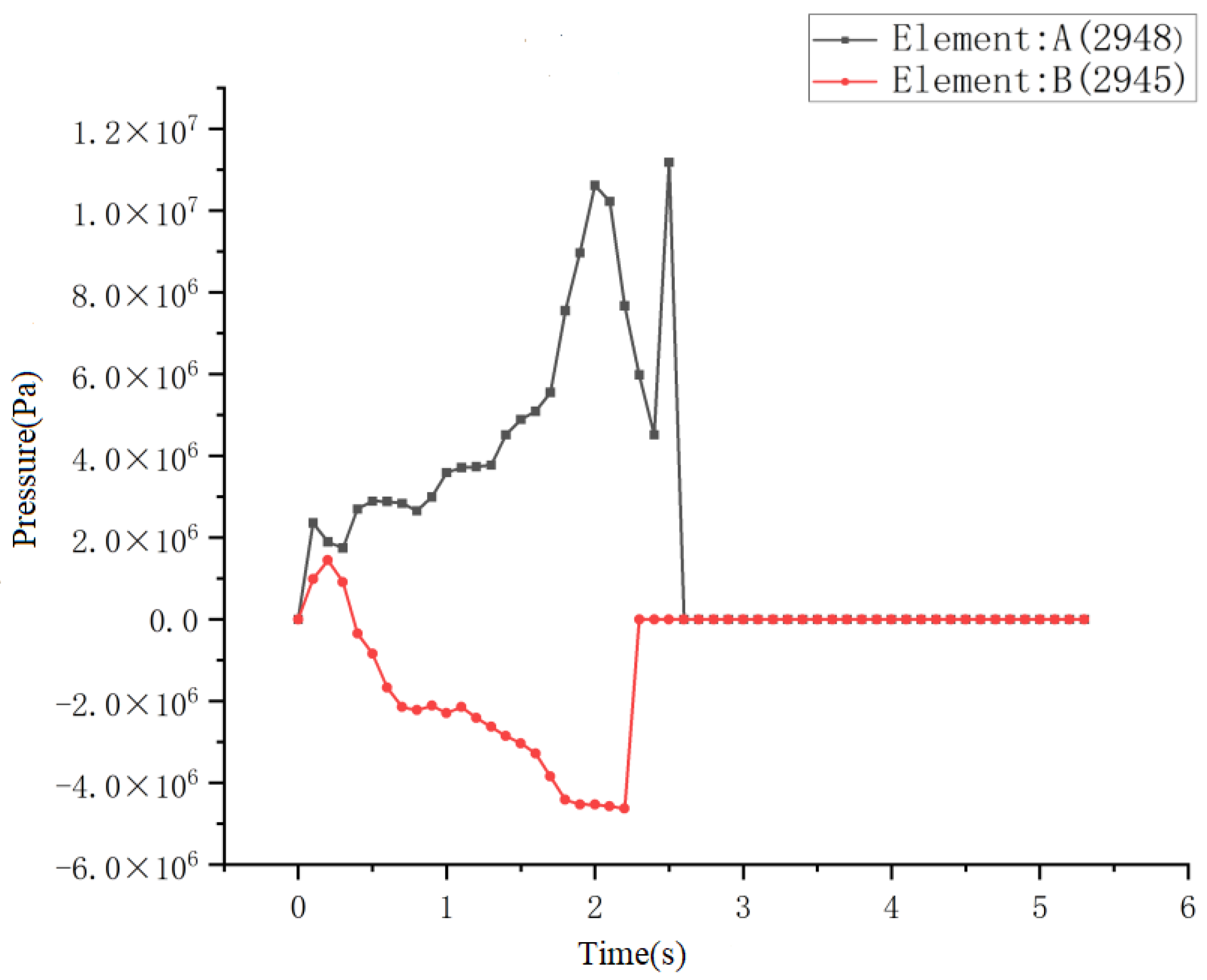
3.4. Force Analysis of Concrete in the Support Area

Select two units A and B at the top of the first floor of the last row of columns. Unit A is located on the inside of the supporting column and unit B is located on the outside of the supporting column. The time-pressure curve of a concrete unit is shown in Figure 9, in which the compressive stress is positive, and the tensile stress is negative.
Figure 9 shows that the rear pillar is always under pressure until 0.2 s after the first row of the pillar-blasting cut is formed. After the formation of the first row of blasting cuts, it is equivalent to four long cantilevers, which generates a large rotating bending moment and backward reaction to the rear column. After 0.4 s, unit B is under tension stress, and then it is in a relatively stable tension state. At t = 2.2 s, the deflection moment generated by the structural gravity of the rear column is greater than the cross-sectional resistance moment, and the outer concrete unit begins to reach yield strength and fails. Therefore, the tensile force of the outer concrete unit increases to 2.2 s and gradually decreases to 0, and plastic hinges begin to appear on the rear column. The inner pressure decreases between 2.2 s and 2.5 s but increases later. This is because the structure belongs to the unstable overturning stage during 2.2 s and 2.5 s, and the bottom concrete unit fails. The upper-structure load is borne by the steel bars, which have a smaller bearing capacity. After t = 2.5 s, the column touches the ground, and the upper structure has the initial velocity of forward movement of the center of mass and the initial velocity of deflection around the center of mass. After the support column on the first floor of the rear row touched the ground, it was subjected to an impact reaction force, resulting in a sudden increase in force on the support column and stress concentration on the inner side. After t = 2.7 s, the concrete unit reached its failure strength and the column broke, causing the inner pressure to decrease to 0 after reaching its maximum value, resulting in a plastic hinge time lasting 0.5 s.

4. Results and Discussion

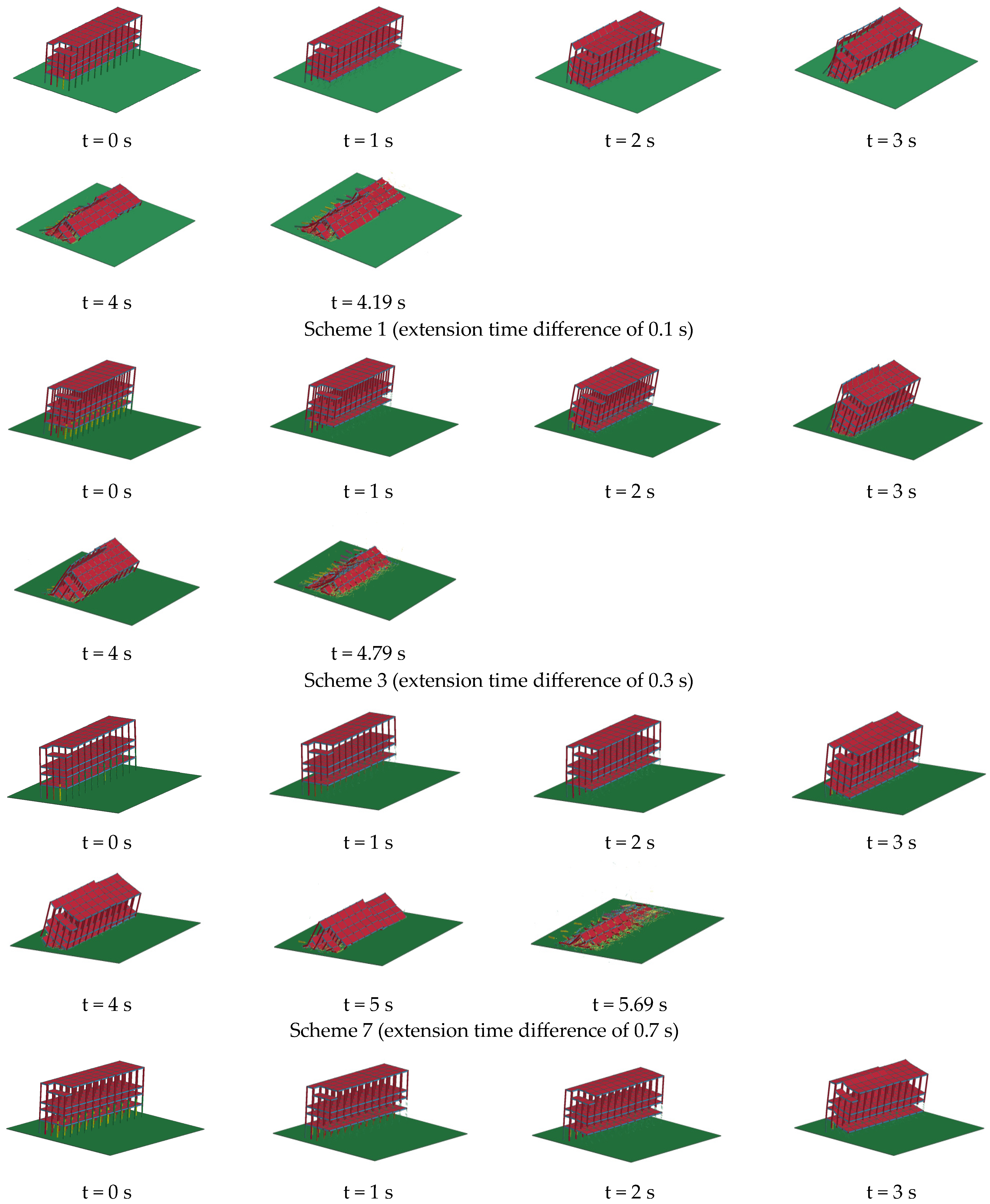
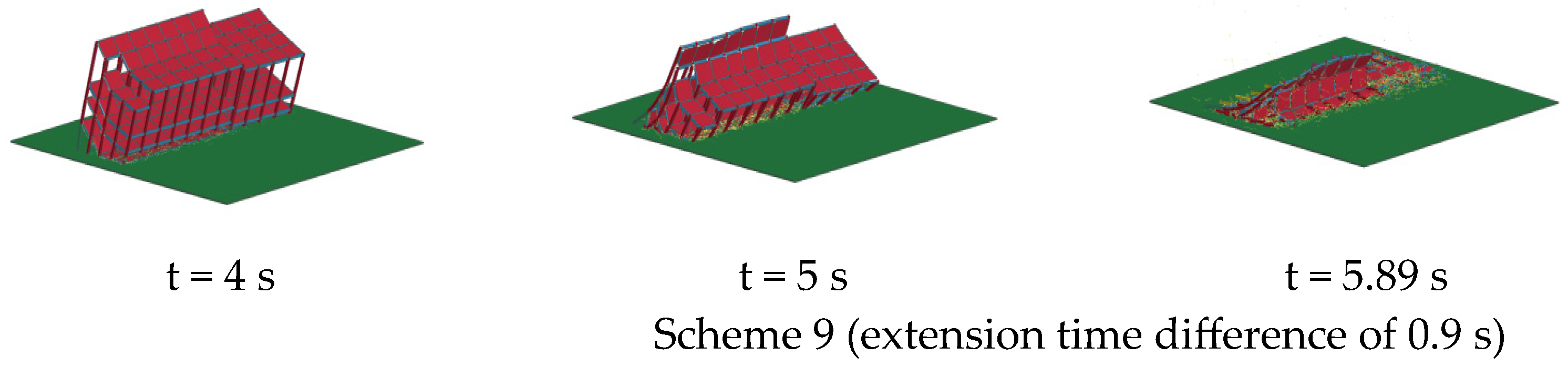
4.1. Effect of Different Extension Time Differences on the Collapse Process

A reasonable time difference in the extension has a crucial influence on the blasting effect of the demolished object [26,27], on the basis of this acid-station workshop model. Only the time difference was changed appropriately, without changing other elements of the model, and the nine time-difference schemes between each row of columns of this small-aspect-ratio reinforced concrete structure were set as follows: 100 ms, 200 ms, 300 ms, 400 ms, 500 ms, 600 ms, 700 ms, 800 ms, 900 ms. Among these scenarios, the blasting effect under a 500 ms time difference was verified. The remaining eight schemes were calculated and simulated separately, and the interfaces of the calculation results of the first, third, seventh and ninth representative schemes were output at an interval of 1 s. Finally, the collapse process ended when the vertical velocity of the structure was less than 0.19 m/s. The four schemes were compared and analyzed, and the collapse processes of the buildings with different delay-time differences are shown in Figure 10.
From Figure 7 and Figure 10, it can be seen that, according to the numerical analysis results, all nine time-difference design schemes can complete the directional collapse according to the preset direction. These figures show the four stages of the blast-incision formation, destabilization overturning, incision closure, and structural touchdown disintegration of this small-aspect-ratio reinforced concrete structure, and each scheme has different collapse patterns in each stage. The time-course collapse attitude of this small-aspect-ratio reinforced concrete structure blasting-demolition numerical simulation is in high agreement with the actual collapse, and the simulation results are more satisfactory.
According to engineering practice and relevant blasting guidelines [28], the plastic hinge is an important parameter in blasting construction and plays a crucial role in the structural-blasting effect. In the short time difference of 0.1~0.3 s, the plastic hinge is not formed between the beams and columns of the A, B, C and D axes in time to make a similar in situ collapse motion in a whole form. Because the beams and columns of the plant are long, after the blast incision at the A, B, C and D axes is detonated, a long cantilever structure will be formed, so that the resisting moment of the beam end at the D and E axes is smaller than the overturning moment generated by the gravity of the upper structure. Because of the short extension time, after the blast incision at the E axis is formed and touches the ground, it will be subject to the vertical upward impact reaction force from the ground, so that plastic hinges will be formed at the ends of the beams at the D and E axes, forming a plastic-deformation zone. As shown in Figure 11a, the bottom of the rear row of columns undergoes a fixed-axis rotation. After entering the collapse stage of the touchdown, the structure will not completely disintegrate because the energy accumulated by the building itself is low, and part of the structure will lose energy after the touchdown. In the time difference of 0.4~0.8 s, with the gradual increase in the postponed time difference, the beam–column nodes have sufficient action time to form plastic hinges, and the rotation of the structure between the rows of columns will provide the horizontal direction velocity component, thus intensifying the overall forward tilt phenomenon of the structure and leading to the flexural plastic hinge at the top of the last column layer, as shown in Figure 11b. In the time difference of 0.4~0.8 s, as the time difference increases, the plastic hinge also has sufficient rotation time to accumulate enough kinetic energy after reaching the state of incision closure, and the plastic hinge dissipates more energy to the extent that the structure disintegrates more completely by touching the ground. The collapse pattern of Scheme 9 and Schemes 1~3 did not have a plastic hinge at the top of the rear row of the first-floor columns, which was due to the long time difference of 0.9 s. This made the plastic hinge between the rows of columns rotate sufficiently. When the plastic hinge was generated in the rear row of columns, the front-row structure had already touched the ground, resulting in insufficient force to make the plastic hinge of the rear row of columns form. The structure of the rear column bottom for the fixed-axis rotation can only form the collapse state of the rear column supported by the beam at D and E.
From the numerical simulation analysis of Figure 10 and Figure 11, it can be seen that in these nine scenarios, when the blast-cut failure of each row of columns is removed, the transverse-force members of the structure (beams and slabs) are in the overhanging state, and at the combination of slabs, beams and columns, they will be subjected to larger moments. Since the column is much larger than the beam and floor in terms of the bearing capacity, lateral-bearing members such as the beam and floor will be damaged before the column. When a long time difference is used, for example, in the time difference of 0.7~0.9 s, due to the characteristics of this structure, the plastic hinge acts for a long time, and the rotation of the superstructure will produce a recoil force in the opposite direction of the overall tipping of the structure. In addition, the premature destruction of the beam and plate will affect the integrity of the structure, which will lead to a relatively large back-slip phenomenon after the structure disintegrates at ground level.

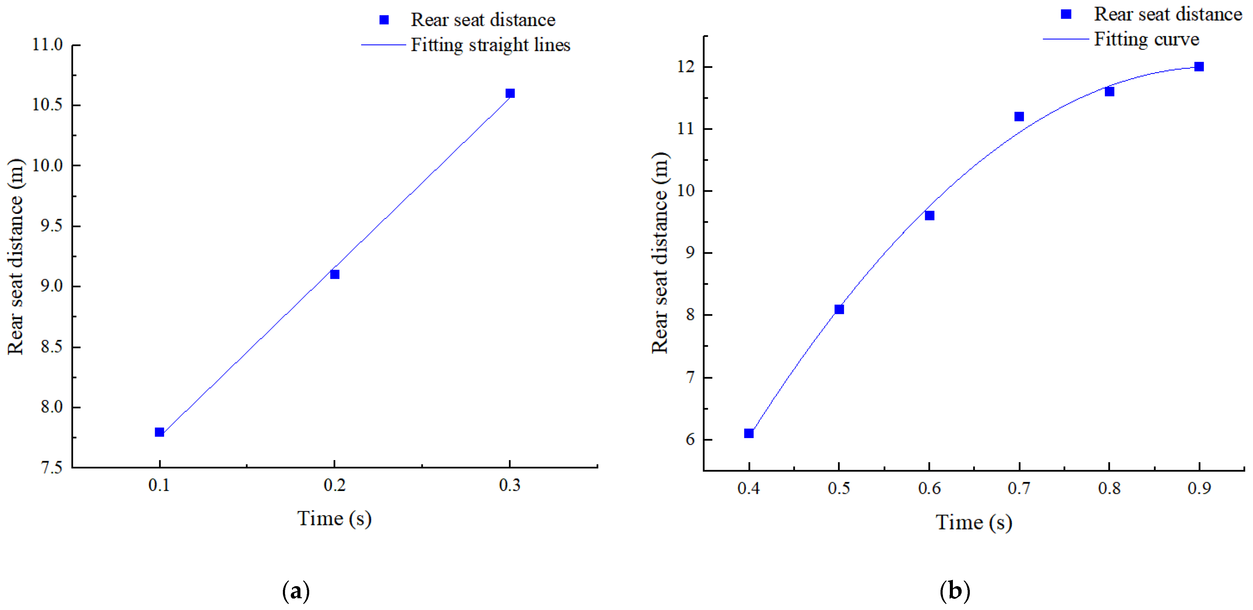
4.2. Effect of Different Extension Time Differences on the Recoil Distance

Due to the characteristics of structures with small-aspect ratios, two plastic hinges with different positions, as shown in Figure 10, appear in 0.1~0.9 s, resulting in the plastic hinge at the top of the rear row of columns in the rear row of the superstructure for fixed-axis rotation when the delay-time difference is 0.4~0.8 s. When the time difference of the extension is 0.1~0.3 s and 0.9 s, the superstructure undergoes a fixed-axis rotation at the bottom of the rear column. Selecting the outermost unit of the blasting pile and outputting the recoil displacement distance can obtain the recoil distance of the structure under different blasting delay-time differences, as shown in Figure 12.
Given the uniqueness and irreversibility of blasting demolition operations, it is difficult to conduct repeated experimental verifications of the demolition process. Numerical simulations can repeatedly simulate the blasting process and continuously optimize the design scheme, making it easy for people to understand and analyze. By comparing the recoil distance and explosion height of structural collapse under different delay-time differences, a reasonable fitting formula can be obtained, and the reasonable delay-time difference of such small-aspect-ratio reinforced concrete structures can be analyzed. As shown in Table 3, when the delay-time difference is 0.1~0.3 s and 0.4~0.7 s, the recoil distance increases with the increase in these two groups of delay-time differences, which is due to the use of delayed detonation. With the increase in the delay-time difference between the columns, the structure leans forward, and the horizontal component of the velocity increases significantly. The greater the acceleration in the horizontal direction is, the greater the reaction force on the rear column. Therefore, the support column slides backwards, and the distance of the backwards rotation will also increase. Moreover, the extension time difference of 0.7~0.9 s is too long, and the recoil distance tends to be close to a constant because, with the increase in the extension time, the plastic hinge rotation produced is sufficient. Thus, the forward angle of the structure and the horizontal component of the kinetic energy increase. Then, the recoil distance of the structure increases, but the horizontal component of the kinetic energy does not infinitely increase, resulting in the recoil distance basically stabilizing at approximately 12 m. To study the growth trend of the structural recoil distance of Table 2, the data were fitted to time differences of 0.1~0.3 s and 0.4~0.9 s, as shown in Figure 13. The fit-degree indices are all 0.99, which is a good fit.
0.1~0.3 s fitted straight line:
d = 6.37 + 14 t
0.4~0.9 s fitted curve:
d = 19.46 t 2 + 36.76 t 5.29
where d is the recoil distance; t is the deferred time difference; and R2 is the degree of fit index.
The analysis of the collapse process with time differences from 0.1 s to 0.9 s shows that the plastic hinge position of the structure changes with the time differences as follows: the plastic hinge is formed at the end of the latter span between 0.1 s and 0.3 s, then moves to the top of the first floor column in the latter row between 0.4 s and 0.8 s, and finally moves to the end of each span at a time difference of 0.9 s. At time differences of 0.1~0.3 s and 0.9 s, the orientation axis is located at the bottom of the latter row of columns, and at time differences of 0.4~0.8 s, the orientation axis and the plastic hinge are in the same position. The recoil distance showed a linear increasing trend of d = 6.37 + 14 t in the time difference of 0.1~0.3 s, plunged between 0.3~0.4 s, and showed a parabolic increasing trend of d = 19.46 t 2 + 36.76 t 5.29 in 0.4~0.9 s. The recoil distance is smaller for the intercolumn extension time difference of this small-aspect-ratio structure at 0.4~0.5 s.

4.3. Effect of Different Extension Time Differences on the Height of the Burst Pile

The height of the blasting pile is related to the degree of disintegration of the building after the collapse and the crushing condition of the concrete, which affects the collection, loading, and transportation of construction waste after blasting. To more intuitively study the impact of different blasting time differences on the height of the burst pile of the structure, the output of the burst pile height of each option is shown in Table 4.
The highest point of the burst pile in each program was selected as the measurement point of the height of the burst pile. The time differences of 0.1~0.3 s and 0.9 s were selected, because the formation of the directional axis of the same location and the formation of the burst pile form is very similar. When the extension time difference is 0.1~0.3 s, the plastic hinge action time is short, and the energy accumulated in the incision closure phase is less. However, with the increase in the time difference, the energy accumulated by the plastic hinge increases. Thus, in the 0.1~0.3 s extension time difference, the height of the burst pile gradually decreases. In the extension time difference of 0.4~0.8 s, with the increase in the column extension time difference, the plastic hinge gradually formed at the beam-column node. When the time difference reaches 0.6 s, the plastic hinge sufficiently rotates, the accumulated kinetic energy is sufficient to allow the structure to touch the ground disintegration, and the pile height reaches a minimum of 6.89 m. The delay-time difference is 0.9 s, and the burst stack height is 8.72 m. This is because, when the plastic hinge action time is too long, the energy changes from kinetic energy into internal energy, and the back row of columns in the deflection of the touchdown process and the beam is still part of the steel connection. This results in a collapse along the D~E axis at the beam to support the back row of columns, which is not conducive to structural disintegration.
h = 21.87 t 2 31.46 t + 18.73
The fit to the height of the burst pile is shown in Figure 14, and the fit indicator is 0.9289, which is a good fit. The height of the burst pile at any time differential trend is h = 21.87 t 2 31.46 t + 18.73 . When the time difference is 0.6 s, the minimum height of the burst pile is 6.89 m. By comparing the nine scenarios of the extension time differences in small height-to-width ratio reinforced concrete structures, it was found that the extension time difference is between 0.5 s and 0.8 s when the burst pile height is relatively low, and the degree of disintegration is high.

4.4. Optimal Solution Selection for Intercolumn Delay-Time Differences

The intercolumn extension time difference on the recoil distance and the impact of the burst stack height are comprehensively considered, if the intercolumn extension time difference optimal solution coefficient index is k, where 0 ≤ k ≤ 1. According to Figure 10 and Figure 11, that show the data analysis, the recoil distance as well as the minimum value of the burst pile height are taken as k = 0.5, and the maximum value of both is k = 0.
According to the results of the mathematical analysis for data fitting, the results of fitting the structural recoil distance indicator k 1 under a 0.1~0.3 s deferred time difference are:
k 1 = 1.25 t + 0.50289
The results of the k 1 fitting of the structural-recoil-distance metric under a 0.4~0.9 s delay-time difference are:
k 1 = 1.73791 t 2 3.28223 t + 1.54343
The 0.1~0.9 s delay-time difference of the fitting results of the structure burst stack height indicator k 2 are:
k 2 = 1.29237 t 2 + 1.85906 t 0.19995
According to Equations (5)–(7), the results of the intercolumn extended time-difference optimal-solution coefficient index k are:
delay-time difference between 0.1 and 0.3 s:
k = 1.29237 t 2 + 0.60906 t + 0.30303
delay-time difference between 0.4 and 0.39:
k = 0.44554 t 2 1.42317 t + 1.34348
Equations (8) and (9) are provided to perform the calculations. At 236 ms, Formula (8) obtains the maximum value of 0.3748; at 400 ms, Equation (9) obtains the maximum value of 0.8455. Therefore, for a smaller height and width than the reinforced concrete structure and taking into account the height of the burst pile and the back sitting distance, the optimal solution for the column delay-time difference at 400 ms is a reasonable range for the column delay-time difference of 400 ms~500 ms.

5. Conclusions

By setting different time differences between rows of columns, the influence law of time difference on the blasting effect was studied, and the purpose of improving the blasting effect was achieved. This provides a reference for reducing the recoil distance, reducing the height of explosive piles, and effectively controlling the explosive pile range of buildings, and will reduce project costs and improve the safety of subsequent construction. The results of this research are as follows.
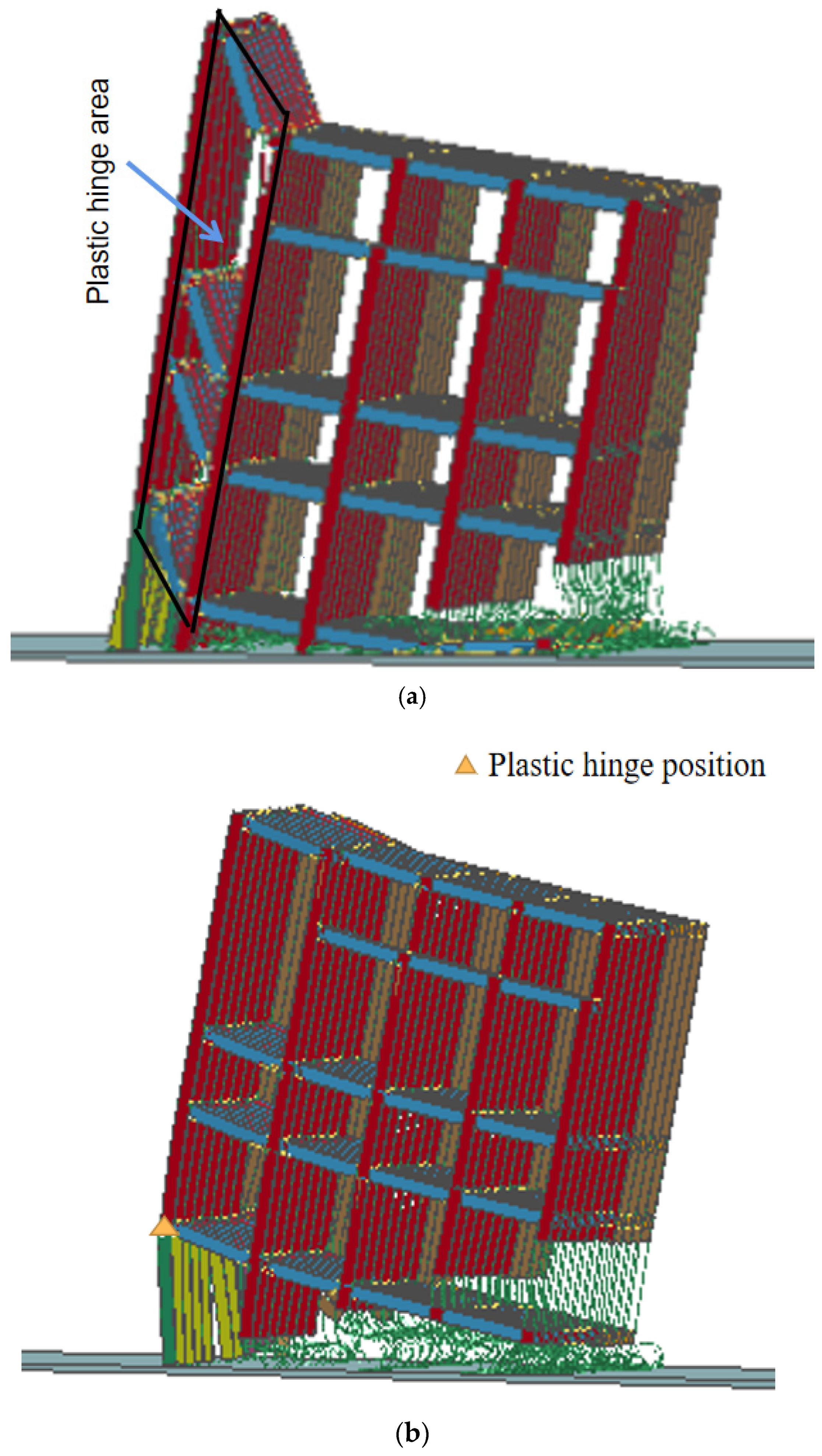
  • The structural plastic hinge is formed at the end of the latter span beam at a time difference of 0.1~0.3 s, moves down to the top of the rear row of the first-floor columns at a time difference of 0.4~0.8 s, and finally moves to the end of each span beam at a time difference of 0.9 s. The position of the structural orientation axis is influenced by the position of the plastic hinge, which is located at the bottom of the rear column at time differences of 0.1~0.3 s and 0.9 s, and is in the same position as the plastic hinge at time differences of 0.4~0.8 s. The blasting effect is better when the plastic hinge of the structure is formed at the top of the rear layer of the columns;
  • The recoil distance shows a linear growth trend of d = 6.37 + 14 t at the time difference of 0.1~0.3 s, plunges between 0.3~0.4 s, and shows a parabolic growth trend of d = 19.46 t 2 + 36.76 t 5.29 at 0.4~0.9 s. For the small-aspect-ratio structure, the recoil distance is smaller at the time difference of 0.4~0.5 s for the extension;
  • The height of the burst pile is h = 21.87 t 2 31.46 t + 18.73 , which represents a parabolic growth pattern. In a time difference between 0.5 s to 0.8 s, the height of the burst pile is relatively low;
  • For small-aspect-ratio reinforced concrete structures, a reasonable range for the intercolumn delay-time difference is 400~500 ms, and the optimal solution is 400 ms. The actual selected blasting solution has an intercolumn extension time difference of 500 ms, which is consistent with the numerical simulation results.
In the actual blasting and demolition process, the impact of the blasting loads generated by explosives in the columns on the collapse of the structure is very complex, and some simplifications made in the numerical simulations are debatable and need further study.
  • Reinforced concrete structures were studied using the separated common node model. Thus, the differences in the mechanical properties of concrete and two steel materials are observed. However, the distribution of the vertical reinforcement and hoop reinforcement makes it difficult to maintain consistency with the actual project. Therefore, a more suitable model for the study of concrete material properties will require further research;
  • The ground is assumed to be a rigid body that does not allow for the analysis of the building’s grounding vibrations caused by blast demolitions. In future simulations, the ground can be modelled as a suitable elastoplastic material;
  • A blast incision is formed by forcing the concrete units to fail directly, which does not reflect the damage and vibration to the surrounding structure when explosives are detonated inside the concrete. Therefore, the research and development on blasting materials using finite element software can be further strengthened.

Author Contributions

Methodology, W.G.; Software, T.Y. and S.L.; Writing—review and editing, H.S.; Writing—original draft preparation, Y.K. All authors have read and agreed to the published version of the manuscript.

Funding

This research was funded by National Natural Science Foundation of China, (Study on rock breaking process and mechanism of cutting blasting in deep high-stress rock roadway) grant number 51874189.

Institutional Review Board Statement

The study did not require ethical approval.

Informed Consent Statement

Not applicable.

Data Availability Statement

The data presented in this study are available on request from the corresponding author. The data are not publicly available due to [the privacy of the data].

Acknowledgments

The present work has been supported by National Natural Science Foundation of China (51874189). These supports are gratefully acknowledged.

Conflicts of Interest

The authors declare no conflict of interest.

References

  1. Aslam, M.S.; Huang, B.; Cui, L. Review of construction and demolition waste management in China and USA. J. Environ. Manag. 2020, 264, 110445. [Google Scholar] [CrossRef] [PubMed]
  2. Chu, H.; Xu, P.; Ye, H. Collapse process and load-bearing process of reinforced concrete chimney during blasting demolition. Vib. Shock 2015, 34, 183–186+198. [Google Scholar]
  3. Ming, Y.; Dai, Q.; Zhao, M. Cause analysis and disposal of explosive demolition failure of two 45 m high cooling tower. Blasting 2016, 33, 118–123. [Google Scholar]
  4. Laszlo, R.; Radeanu, C.; Ilici, S.; Grecea, M.; Levente, M. Technical and safety aspects at the demolition by blasting works of a cooling tower with a high of 72.00 m. MATEC Web Conf. 2020, 305, 72. [Google Scholar] [CrossRef]
  5. Wang, S.; Zhang, J.; Li, J.; Kong, F.; Fan, J. Analysis of Vibration Attenuation and Energy Consumption of Blasting Demolition Chimney: A Case Study. Teh. Vjesn.-Tech. Gaz. 2020, 27, 826–834. [Google Scholar]
  6. Bažant, Z.P.; Verdure, M. Mechanics of Progressive Collapse: Learning from World Trade Center and Building Demolitions. J. Eng. Mech. 2007, 133, 308–319. [Google Scholar] [CrossRef]
  7. Sun, J.; Jia, Y.; Yao, Y.; Xie, X. Experimental investigation of stress transients of blasted RC columns in the blasting demolition of buildings. Eng. Struct. 2020, 210, 110417. [Google Scholar] [CrossRef]
  8. Wang, S.; Gong, M. Numerical Simulation Study on Blasting Demolition of 84 m Tall Building. IOP Conf. Ser. Earth Environ. Sci. 2019, 252, 022145. [Google Scholar] [CrossRef]
  9. Isobe, D.; Jiang, R. Explosive demolition planning of building structures using key element index. J. Build. Eng. 2022, 59, 104935. [Google Scholar] [CrossRef]
  10. Sun, J.; Jia, Y.; Xie, X.; Yao, Y. Design criteria for the folding implosion of high-rise RC buildings. Eng. Struct. 2021, 233, 111933. [Google Scholar] [CrossRef]
  11. Kangda, M.Z.; Bakre, S. The Effect of LRB Parameters on Structural Responses for Blast and Seismic Loads. Arab. J. Sci. Eng. 2018, 43, 1761–1776. [Google Scholar] [CrossRef]
  12. Wang, Z.; Wang, H.; Wang, J.; Tian, N. Finite element analyses of constitutive models performance in the simulation of blast-induced rock cracks. Comput. Geotech. 2021, 135, 104172. [Google Scholar] [CrossRef]
  13. Jia, H.; Tian, S. Research and Application of a Reinforced Concrete Simplified Model. Adv. Civ. Eng. 2021, 2021, 8861831. [Google Scholar] [CrossRef]
  14. Min, G.; Fukuda, D.; Cho, S. 3D Numerical Analysis Method for Simulating Collapse Behavior of RC Structures by Hybrid FEM/DEM. Appl. Sci. 2022, 12, 3073. [Google Scholar] [CrossRef]
  15. Yan, B.; Liu, M.; Meng, Q.; Li, Y.; Deng, S.; Liu, T. Study on the Vibration Variation of Rock Slope Based on Numerical Simulation and Fitting Analysis. Appl. Sci. 2022, 12, 4208. [Google Scholar] [CrossRef]
  16. Zhai, X.; Wu, S.; Li, H.; Wang, K.; Wang, W.; Song, X. Experimental and numerical investigation on dynamic behaviors of the concrete wall in underground coal mine with hydraulic blasting demolition. J. Vibroeng. 2017, 19, 2043–2062. [Google Scholar] [CrossRef] [Green Version]
  17. Chai, Y.; Luo, N.; Zhang, H.; Duan, Y.; Sun, W.; Dong, J. Application of controlled blasting demolition technology in ultra-high coaxial thin-walled steel inner cylinder reinforced concrete chimney. Case Stud. Constr. Mater. 2023, 18, e01936. [Google Scholar]
  18. Zhou, X. Simulation Calculation of the Collapse Process of High-Rise Steel Structure Energy-Forming Cutting Blasting Demolition. Wirel. Commun. Mob. Comput. 2022, 2022, 3735006. [Google Scholar] [CrossRef]
  19. Hu, Y.; Yang, Z.; Yao, E.; Liu, M.; Rao, Y. Investigation and Control of the Blasting-Induced Ground Vibration under Cold Condition. Shock Vib. 2021, 2021, 6660729. [Google Scholar] [CrossRef]
  20. Singh, C.P.; Agrawal, H.; Mishra, A.K. A study on influence of blast-induced ground vibration in dragline bench blasting using signature hole analysis. Arab. J. Geosci. 2020, 13, 522. [Google Scholar] [CrossRef]
  21. Song, W.; He, P. Safety regulations for blasting (GB 6722-2014) Released. Eng. Blasting 2015, 21, 62. [Google Scholar]
  22. Yue, H.Z.; Yu, C.; Li, H.B.; Zhou, C.B.; Chen, S.H.; Shao, Z.S. The Effect of Blast-Hole Arrangement, Delay Time, and Decoupling Charge on Rock Damage and Vibration Attenuation in Multihole Blasting. Shock Vib. 2022, 2022, 2110160. [Google Scholar] [CrossRef]
  23. Cai, R.; Li, Y.; Zhang, C.; Cao, H.; Qi, H.; Mao, J. Size effect on reinforced concrete slabs under direct contact explosion. Eng. Struct. 2022, 252, 113656. [Google Scholar] [CrossRef]
  24. Fouad, M.; Fayed, M.N.; Hamdy, G.A.; Abdelrahman, A. Effect of Blast Loading on Seismically Detailed RC Columns and Buildings. Civ. Eng. J. 2021, 7, 1406–1425. [Google Scholar] [CrossRef]
  25. Peerasak, A.; Kazunori, F.; Piti, S. Feasibility Study on Novel Blasting Technique Using Linear-Shaped Charges to Cut Reinforcing Steel Bars in Reinforced Concrete Members. Pract. Period. Struct. Des. Constr. 2023, 28, 04023013. [Google Scholar]
  26. Song, Z.; Ke, M.; Liu, X. Identifying Delay Time of Detonator for a Millisecond Blasting. Adv. Civ. Eng. 2021, 2021, 5592696. [Google Scholar]
  27. Ji, C.; Gao, F.; Li, X.; Yu, Y.; Cheng, L. Numerical analysis of vibration-isolating effect of vibration-isolating slot under buried pipe subjected to millisecond blasting. Vibroeng. Procedia 2018, 21, 32–37. [Google Scholar] [CrossRef] [Green Version]
  28. Gao, B.; Wu, J.; Zhao, R.; Feng, X.; Wang, Z. Residual seismic resistance of CFDST columns after a close-in explosion: Experimental study. Structures 2023, 48, 1082–1101. [Google Scholar] [CrossRef]
Figure 1. Traffic location map.
Applsci 13 06765 g001
Figure 2. Plan of the acid-station workshop to be demolished and the direction of the blasting collapse.
Applsci 13 06765 g002
Figure 3. Principle of the separated co-node model. (a) The force situation of the structure in the normal working stage. (b) The force situation of the structure after the formation of blasting cuts.
Applsci 13 06765 g003
Figure 4. Model establishment flowchart.
Applsci 13 06765 g004
Figure 5. Concrete structure model drawing.
Applsci 13 06765 g005
Figure 6. Steel structure model diagram.
Applsci 13 06765 g006
Figure 7. Comparison of the actual collapses and numerical simulation of the collapsing process.
Applsci 13 06765 g007
Figure 8. Comparison of the actual burst pile and simulation: (a) actual burst pile; and (b) simulation burst pile.
Applsci 13 06765 g008
Figure 9. Time history curve of concrete unit pressure.
Applsci 13 06765 g009
Figure 10. Schematic diagram of the collapse process simulated numerically with different extension time differences.
Applsci 13 06765 g010aApplsci 13 06765 g010b
Figure 11. Schematic diagram of the plastic-hinge formation position. (a) Plastic hinges are formed at both ends of D and E axis beams. (b) Plastic hinge appears at the top of the first layer of the last row of columns.
Applsci 13 06765 g011
Figure 12. z-axis direction unit displacement time curve.
Applsci 13 06765 g012
Figure 13. Fit of the recoil distance relationship: (a) 0.1~0.3 s recoil distance fitting; and (b) 0.4~0.9 s recoil distance fitting.
Applsci 13 06765 g013
Figure 14. Burst stack height relationship fitting.
Applsci 13 06765 g014
Table 1. Structural properties.
Structure
Properties
Total Length/mWidth
/m
Total Height/mNumber of FloorsSpacing between Each Row in the North-South
Direction/m
East-West Pillar Spacing/m
Numerical value1002534.4469
Table 2. Physical and mechanical parameters of the materials.
NameDensity
/ kg · m 3
Modulus of
Elasticity/GPa
Poisson’s RatioStretching Limit/MPa
Reinforcing Steel78502100.3320
Beams and Columns2500350.185.8
Board3400350.185.6
Table 3. Structure recoil distance under different extension time differences.
Analysis TypeData Results
Delayed time difference (s)0.10.20.30.40.50.60.70.80.9
Recoil distance (m)7.89.110.66.48.19.611.211.612.0
Table 4. The height of the burst pile under different extension time differences.
Analysis TypeData Results
Delayed time difference (s)0.10.20.30.40.50.60.70.80.9
Burst height (m)15.3513.2111.6211.407.606.897.377.218.72
Disclaimer/Publisher’s Note: The statements, opinions and data contained in all publications are solely those of the individual author(s) and contributor(s) and not of MDPI and/or the editor(s). MDPI and/or the editor(s) disclaim responsibility for any injury to people or property resulting from any ideas, methods, instructions or products referred to in the content.

