Article

Modeling of Walking-Gait Parameters and Walking Strategy for Quadruped Robots

1
School of Aerospace Engineering, Xiamen University, Xiamen 361102, China
2
School of Automotive Engineering, Shandong Jiaotong University, Jinan 250357, China
3
Shandong Academy of Agricultural Machinery Sciences, Jinan 252100, China
*
Author to whom correspondence should be addressed.
Appl. Sci. 2023, 13(12), 6876; https://doi.org/10.3390/app13126876
Submission received: 14 April 2023 / Revised: 30 May 2023 / Accepted: 30 May 2023 / Published: 6 June 2023
(This article belongs to the Special Issue Advanced Pattern Recognition & Computer Vision)

Abstract

:
The inspiration for the footed robot was originally derived from biology, and it was an imitation of biological form and movement. In this paper, a bionic-robot dog is designed to reveal the motion characteristics of a quadruped robot mechanism through modeling, model kinematic analysis, and other methods. First, the structural characteristics and movement characteristics of the developed bionic-dog model are studied. The first step is to study the physiological structure of the dog, analyze the function of the dog’s limbs, and then use a high-speed camera to capture the motion of the marked bionic-robot dog and shoot motion video of the bionic-robot dog in different motion states. The effective data of the marked points in the video are extracted using PHOTRON 1.0 software, and the extracted data are analyzed and processed in the software MATLAB R2020a, and finally the structural characteristics and motion laws of the bionic-robot dog are obtained. Then, a bionic-robot-dog experimental platform is built to conduct experiments with three planned gaits (dynamic gait, static gait, and gait transition). The experiments showed that the three gaits were consistent with the planned movements and the bionic-robot dog could perform stable fast-gait walking, slow-gait walking, and quickly complete gait transitions. All three gaits were simulated in ADAMS 2019 software, and the simulation results showed that all three gaits caused the bionic dog robot to move smoothly.

1. Introduction

Robot technology is an emerging technology that integrates computer technology, sensing technology, and vision technology [1]. It is undoubtedly one of the frontier areas of today’s scientific and technological development [2]. In recent years, with the rise of artificial intelligence, robotics technology has developed vigorously, and its research has gradually expanded from the traditional industrial scope to new fields such as biomedicine, educational services, and exploration and rescue [3]. The prevalence of robots in daily life is increasingly evident. For example, pet robotic dogs can often be seen taking walks with their owners, while rescue robots are frequently deployed in disaster areas, providing a glimmer of hope for victims [4]. In addition, there are also small robots engaged in express sorting and load-bearing robots engaged in cargo transportation. The development of robot technology has made life more comfortable and faster [5].
Mobile robots are an important part of robotics technology. An increasing number of scientific research institutions have been dedicating significant human and material resources to research on mobile robots, due to their broad application markets and promising prospects [6]. One of the research hotspots in the field of mobile robots is footed robots. The reason is that nearly half of the terrain in the natural environment cannot be reached by wheeled or crawler robots, such as forests, grasslands, and disaster areas [7]. Forests and grasslands are rich in resources, and disaster areas also need robots to find affected people and bring necessary supplies [8]. Compared with wheeled or crawler robots, the discrete-point-like feet of footed robots when they contact the ground are more suitable for non-continuous plane ground such as forests and disaster areas. Therefore, footed robots play an important role in human service and well-being and life [9]. Limbed robots are classified according to the number of feet, and the common ones are biped, quadruped, and hexapod [10]. Obviously, compared with two-limbed robots, quadruped robots have the characteristics of stable motion, diverse motion forms, and strong carrying capacity [11]. Compared with hexapod robots, and those with even more limbs, quadruped robots have simpler structure and easy-to-establish motion models, so quadruped robots appear more frequently in scientific research and life [12]. The quadruped robot can adjust its movement gait according to different environments and different speeds [13]. The accessibility of the ground and the pitch of the ground slope will affect the quadruped robot’s choice of gait, which leads to a variety of movements by the quadruped robot. Common periodic symmetrical gaits on unobstructed hard surfaces include wave gait, diagonal gait, and running gait. At present, researchers have investigated single gaits of quadruped robots more, including the planning of foot trajectories, the coordination between the four limbs, and analysis of the stability of the whole machine. Many models have been proposed, such as the linear inverted-pendulum model and the virtual-limb model [14]. For foot-trajectory planning, an elliptical trajectory and a parabolic trajectory have been proposed [15].
This study found that, although the above research trajectories are diverse, their biological diversity is not strong. In addition, researchers have done little research on the gait transition process, and the research volume for this is far less than the research on single gaits. On the one hand, the gait-transition process itself is relatively complicated, and accurate calculation is required between the two gaits to achieve a smooth transition. On the other hand, during the gait-transition process, the stability and coordination of the whole machine must be greatly tested. Considering the existing bionic quadruped robots, it can be seen that in terms of the robot’s body structure, its joints are limited, and there is still a significant gap compared to flexible organisms. This study designs a quadruped robot based on research results on the structure and gait of biological dogs. While ensuring stable motion for the robot, this study considers limb coordination and plans reasonable low-speed gaits, high-speed gaits, and transition gaits. The aim is to solve the problems of insufficient bionics in single-gait planning and of coordination in multi-gait transitions, providing a reference for research on bionic robots.
The structure of this article is arranged as follows. Section 1 elaborates on the background and significance of this research, and it presents the research content and objectives of this article. Section 2 studies the structural characteristics and motion patterns of biological dogs. In Section 3, the mechanical structure of the bionic-robot dog is designed, the kinematics of the single limb and the whole machine are analyzed, and the kinematic model is established. In Section 4, based on the motion laws of the biological dog, we design three gait types for the bionic-robot dog, a low-speed gait, a high-speed gait, and a transition gait, and verify the feasibility of the gaits. Section 5 summarizes the research contents and achievements of this paper.

2. Materials and Methods

2.1. Analysis of the Movement Characteristics of the Biological Dog

One of the focuses of quadruped robot research is its gait. Different gaits correspond to different movements of the robot [16]. A good gait does not only improve the stability of the quadruped robot, but also minimizes the fluctuation of its energy consumption, and, therefore, energy can be optimized [17]. As a result of evolution, organisms have achieved a high degree of conformity with the environment in their shape, structure, and movement patterns [18]. The current state of evolution can be said to be the optimal state in the biological environment. The bionic quadruped robot imitates the creature in shape and movement, so that the robot can approximate the movement of the creature in the same biological environment [19]. Since the quadruped robot is moderate in size and easy to control, its movement can be well observed [20].
The research object of this paper is a bionic-robot dog. Compared with bipeds, quadrupeds are more stable. When subjected to lateral force or moving on uneven and rough roads, the biological dog can quickly adjust the position of its center of gravity to bring the body into a state of balance. Compared to robots with hexapods and above, quadrupeds have simpler locomotion patterns. Furthermore, the biological dog is moderate in size, easy to domesticate, and can carry out various exercise experiments. When designing a bionic-robot dog, imitating the shape and movement of a biological dog can improve the environmental adaptability of the robot and make its movement more reasonable. To study the bionic-robot dog, the structural characteristics and motion laws of the biological dog should be studied first, so as to provide a basis for the mechanism design.
An important feature of the bionic robot was that the body structure of the robot was designed to imitate the biological structure in nature. In the process of designing the limb structure, we referred to the limb structure of the dog. The quadruped robot needed to move forward and backward like a living creature. For a series of actions such as steering, each limb must have several freely rotatable joints. Each limb of the robot in this paper was designed with 2 active joints and 1 passive joint. The two active joints were located in the thigh limb. One active joint that could rotate 180 degrees was at the connection with the calf, and another active joint that could rotate 180 degrees was at the connection between the thigh and the torso. The passive joint was for passive adjustment when the foot of the robot was in contact with the ground. After completing the design of the joints of the robot’s limbs, the design of the posture relationship between the torso and the limbs of the robot was carried out. Referring to the two-symmetrical model of the quadruped limb structure in bionics, usually the two front limbs of a robot have the same size and structure, and the two hind limbs have the same size and structure. Therefore, it was only necessary to determine the structure of the front and hind limbs.
After the above analysis, the robot limbs in this paper were designed with a total of 12 joints, including 4 active joints at the hip joints and 4 joints at the knee joints, and 4 passive joints at the feet. For each limb, the 2 active joints of the knee joint and the hip joint controlled the forward and backward movements of a limb of the robot and the movements of raising and dropping the limb, respectively. The passive joints were used to simulate the impact of the soles of the feet when the limbs land. The topological structure of the robot suggested a limb structure with better symmetry and more convenient motion analysis. Then, we processed the video captured of the biological dog’s motion. Using Fastcam Analysis in the video-processing software PHOTON 1.0 to extract the position coordinates of marker points, we analyzed and processed the extracted coordinate data in MATLAB R2021a.

2.2. Analysis of the Movement Law of the Biological Dog

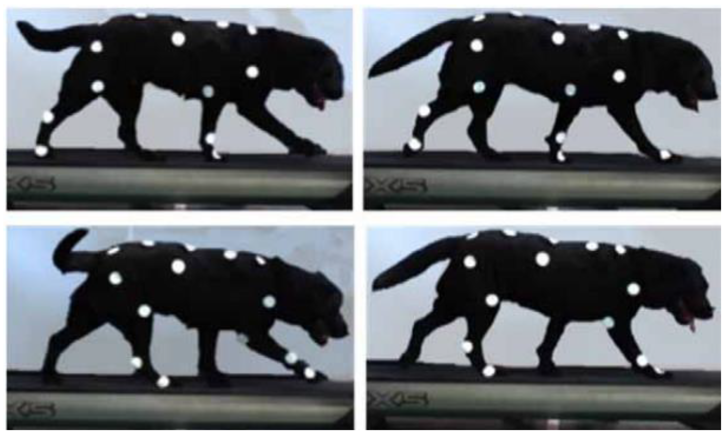
This article used an adult Labrador Retriever as the object to capture the motion of a biological dog. The experiment was conducted indoors. To ensure sufficient time for motion capture, two LED lights were used indoors for lighting, as shown in Figure 1, for the experimental images of the biological-dog motion capture.
This experiment selected a Labrador dog weighing 25 kg. When standing, the length from head to coccyx was 660 mm. The height from the middle of the body to the foot was 460 mm. The body width was 210 mm. For ease of labeling, we chose a pure black Labrador dog.
The experimental steps were as follows:
(1)
Two weeks before the experiment, the dog trainer trained the Labrador dog on a treadmill until it could move freely on the treadmill.
(2)
White circular paper pieces with a diameter of 40 mm were used as marking points and pasted on the Labrador dog, marking 14 points. There were four points in the front limb, namely, the foot end, wrist joint, elbow joint, and shoulder joint. There were four points on the hind limb, namely, the foot end, ankle joint, knee joint, and hip joint. The back was divided into 4 sections and labeled with 5 points: S1, S2, S3, S4, and S5. There was a point in the center of the side of the body.
(3)
The treadmill speed was set to 2 k/h, and the dog trainer directed the movement of the Labrador dog. After the Labrador dog was adjusted, the treadmill accelerated to 3.5 km/h.
(4)
After the Labrador dog stabilized at a speed of 3.5 km/h, a high-speed camera, model FASTCAM Mini UX100, was used to capture a motion video at 500 Hz in this state.
(5)
Experimental steps (3) to (4) were repeated and sports videos were shot at four speeds: 4.0 km/h, 6 km/h, 6.5 km/h, and 7 km/h.
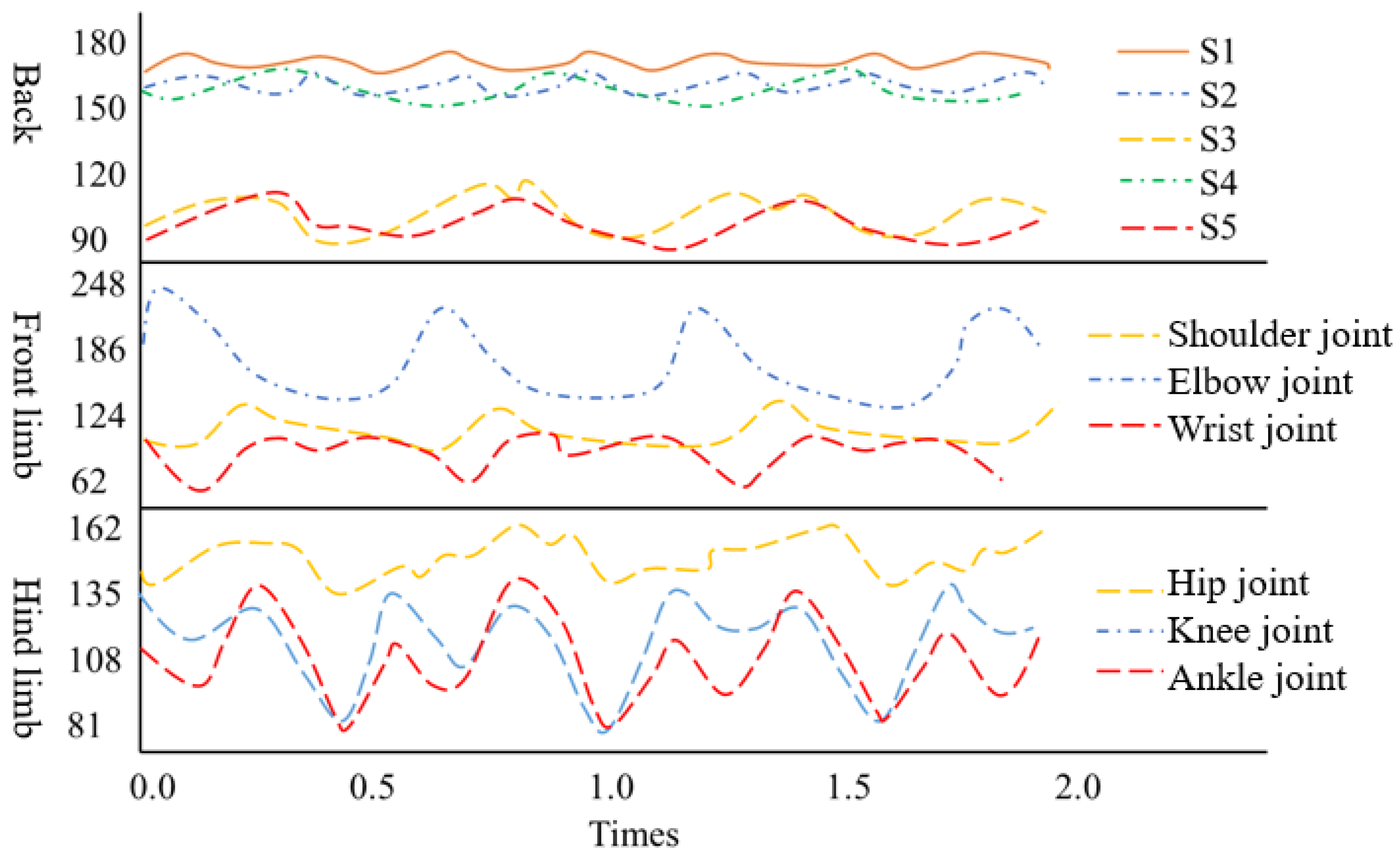
During the experiment, it was found that the range of change in each joint angle was significantly greater when the movement speed was high than when the speed was low. In order to determine the joint-angle range of the bionic-robot dog, the change in the joint angle of the biological dog when the speed was high was analyzed. Figure 2 shows the change in each joint angle at 7.0 km/h.
From Figure 2, it can be concluded that:
(1)
The change trend of the three joints of the hind limb was similar to that of the three joints of the front limb.
(2)
The change trend and angle range of the knee joint and ankle joint of the hind limb were basically the same.
(3)
The back angle did not change much during the exercise.
(4)
The variation range of the hip-joint angle was [150°, 160°], and the variation ranges of the knee-joint and ankle-joint angles were [90°, 130°].
The biggest difference between the motion of a quadruped robot and that of a wheeled robot is that the forward and backward movements of a quadruped robot follow a regular gait. The four limbs of the robot need to be coordinated to ensure smooth movement. Without regular movement, it is difficult for the body of a quadruped robot to maintain balance. However, the motion of wheeled robots does not require this consideration of maintaining balance. As long as the ground is level, wheeled robots can maintain balance. Therefore, gait pattern is a unique requirement of quadruped robots. Gait refers to the regular movement process of a robot’s limbs continuously switching from state A to state B within a fixed motion cycle. Through the coordinated movement of four limbs, the robot’s body can move smoothly forward or backward. The focus of this article is on the walking and jogging states of robots.
The walk gait is a static step, which is the most common walking step in the movement of quadrupeds. The movement is characterized by a certain regularity in the movement of the quadrupeds. It satisfies the support state with three limbs on the ground, the swing phase with one limb off the ground, the movement of four feet satisfies the stability margin, and the movement speed of the center of mass during the forward process is slow, and the body swings less up and down [21]. The walk gait of the quadruped robot in this paper mainly refers to the motion law of quadrupeds represented by dogs, and is used in the analysis of the law of motion period, load factor, swing phase, support, and other parameters in the process of motion.

2.3. Kinematic Analysis of the Quadruped Robot

The topological structure of a robot mainly refers to the connection structure between the robot’s trunk and limbs, as well as the spatial modeling and joint analysis of each limb of the robot. The joints in the robot body structure refer to controllable autonomous motion joints that can actively adjust the robot’s motion angle. Robots with relatively simple body structures often have fewer joints, more convenient control, and lower costs, but can perform fewer actions and have poor bionic performance. The more limb joints a robot has, the more complex are the actions it can complete. However, the cost will also increase, and the structural design of the robot will become more complex, making control more difficult. Therefore, the decision on the number of joints in the limbs is very important.
The bionic-robot dog consisted of approximately 200 parts, with a total length of 775 mm, a total width of 380 mm, and a standing height of 438 mm. The body structure was mainly divided into three sections, the front limb, the back, and the hind limb. Due to the small change in back angle during the movement of the bionic-robot dog, in order to simplify the structure and make the model simpler, a rigid back without joints was used for the back. Similarly, because the movement patterns of the front and hind limbs were similar during movement, the front and hind limbs adopted the same structure. The entire machine had a total of 12 joints, and all 8 active joints were driven by Maxon DC brushless motors, with the motor model being the EC45 Flat. The transmission between the motor and each limb used a belt transmission. Figure 3 shows an assembly diagram of the bionic-robot dog established in the 3D software SolidWorks 2022.
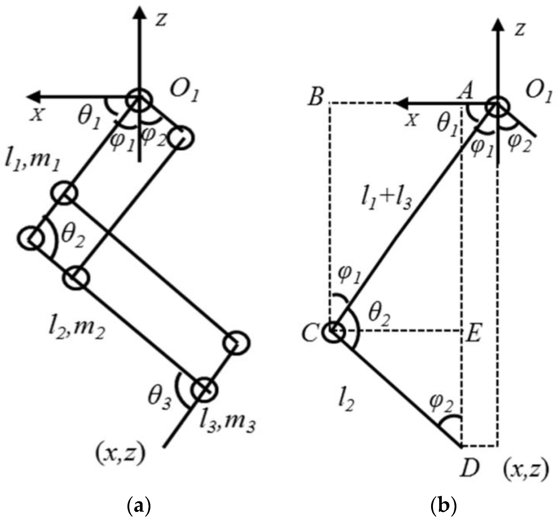
Figure 4 is a linkage schematic of the mechanical structure of the bionic-robot dog. M is the overall mass of the machine. l0 is the distance between the shoulder joints of the front and hind limbs. b0 is the distance between the hip joints of the left and right limbs. ll, l2, l3 and m1, m2, m3 are the lengths and masses of the thigh, calf, and foot, respectively. φ1 is the angle at which motor 1, driving the hip joint, rotates. φ2 is the angle at which motor 2, driving the knee joint, rotates. θ1 is the rotation angle of the hip joint. θ2 and θ3 are the rotation angles of the knee and ankle joints, respectively.
The main parameters in the structural design of the bionic-robot dog and the actual parameters of the biological dog are shown in Table 1. The design parameters should be as close as possible to the actual parameters of the biological dog. Considering the motion stability of the bionic-robot dog, the robot dog was slightly wider in the width direction than the biological dog. After calculation, the size ratio of the robot dog to the reference biological Labrador dog in this article was around 1.

3. Results and Discussion

3.1. Kinematic Analysis of the Bionic-Robot Dog

The bionic-robot dog was mainly composed of the back and four limbs. The four limbs had the same structure. The kinematic analysis of the bionic-robot dog was divided into the kinematic analysis of the single limb and the kinematic analysis of the whole robot mechanism.
The thigh, calf, and foot end of one limb were in the same plane. Figure 5a shows the structural diagram of one limb. Translate the lower limb and foot end, and keep the foot-end position unchanged, to obtain a structural equivalent diagram as shown in Figure 5b. Consistent with the previous text, φ 1 shows the angle of rotation of motor 1 driving the hip joint. φ 2 is the angle of rotation of motor 2 that drives the knee joint. θ1 is the rotation angle of the hip joint. θ2 and θ3 are the rotational angles of the knee and ankle joints, respectively.
In the structural design, because the thigh and the foot of the biological dog have similar motion laws, the designed knee joint and ankle joint have the same motion angle, that is, θ2 = θ3. The hip-joint motion angle and the drive angle of motor 1 are mutually complementary, that is, θ1 + φ 1 = π/2. In addition, in the parallelogram structure composed of the thigh, l1, l2, and calf, the motor drive angles φ1 and φ2 and the knee-joint rotation angle θ2 are adjacent angles of the parallelogram and have a complementary relationship, that is, θ2 = π − (φ1 + φ2). According to the geometric relationship of the single-limb structure, the position of the foot end is uniquely determined by the driving angles of the hip motor and knee motor. Establish a coordinate system (X, Z), which is fixed to the hip, and set the foot-end coordinates to (x, z). The driving space composed of (x, z) and φ1 and φ2 has a certain mathematical relationship, which can be expressed as Equation (1):
x = X φ 1 , φ 2 z = Z φ 1 , φ 2
In the equivalent diagram of the single-limb mechanical structure, ∠BCO = φ1, ∠CDA = φ2, then the forward kinematic relationship can be expressed as Equation (2):
x = O 1 B A B = O 1 B C E = l 1 + l 3 sin φ 1 l 2 sin φ 2 z = D E A E = D E B C = l 1 + l 3 cos φ 1 l 2 cos φ 2
It can be seen from Table 1 that the range of motion of the hip joint was [40°, 110°], and the range of motion of the ankle joint was [80°, 150°]. The relationship between each joint and the motor drive angle is as in Equation (3):
θ 2 = θ 3 θ 1 + φ 1 = π 2 θ 2 = π φ 1 + φ 2
Based on the range of motion of each joint and the relationship between each joint and the motor drive angle, it can be concluded that the value ranges of φ1 and φ2 were [−20°, 50°] and [−20°, 120°], respectively. Combined with the kinematic forward calculation relationship shown in Equation (2), the reachable workspace of the foot in the hip coordinate system can be obtained.
Next, the inverse kinematics of the single limb were analyzed. In the previous section, the forward kinematic equation of the single limb had been obtained as Equation (2), and now the forward kinematic equation is derived, as in Equation (4):
x + l 2 sin φ 2 = l 1 + l 3 sin φ 1 z + l 2 cos φ 2 = l 1 + l 3 cos φ 1
Square both sides, add and arrange to get Equation (5):
x sin φ 2 + z cos φ 2 = l 1 + l 3 2 l 2 2 x 2 z 2 2 l 2
So far, the expressions of the motor drive angle φ1 at the hip joint and the knee motor drive angle φ2 can be obtained from Equations (4) and (5), respectively. If we know the position of the dog foot end, we can calculate the corresponding driving angle and complete the inverse kinematic analysis of the single limb.

3.2. Kinematic Analysis of the Whole Robot Mechanism

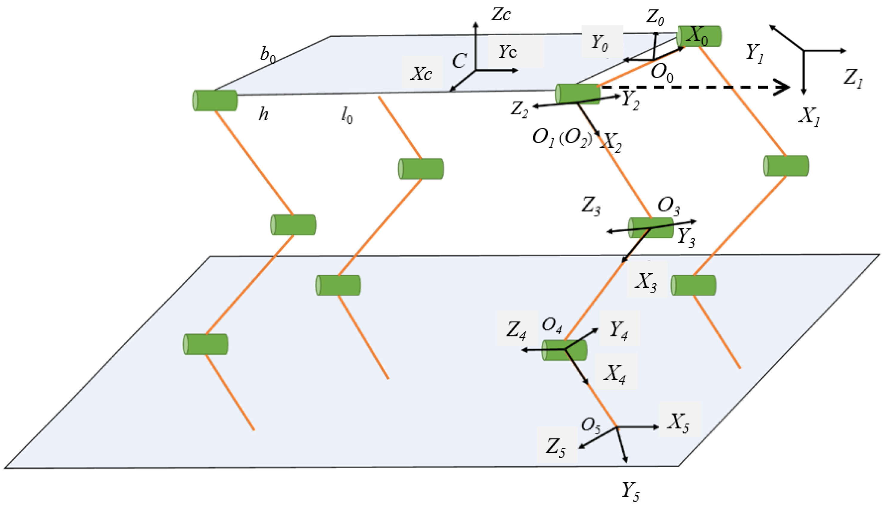
Figure 6 shows the kinematic parameters of the bionic-robot dog. Due to the symmetry of the four limbs, the right-front limb was taken as an example for analysis. The body coordinate system {C} is established at the initial position of the center of mass of the body, the Yc axis is the forward direction, and the Zc axis is the vertical return. The coordinate system {O0} is shown in the figure, and the shoulder has two joints: forward and backward swing and left and right swing. Therefore, the {O1} coordinate system is fixed to the shoulder and corresponds to the left- and right-swing coordinate system. The {O2} coordinate system is the coordinate system corresponding to the forward and backward swing. Since the coordinate system {O2} of the hip joint swinging back and forth is coincident with the coordinate system {O1} of the left- and right-swinging of the hip joint, l1 = 0 in the equation. {O3} is the coordinate system corresponding to the knee joint. {O4} is the coordinate system corresponding to the ankle joint. {O5} is the coordinate system at the end of the foot. θ1 is the angle at which the shoulder joint swings left and right. θ2 is the angle at which the shoulder joint swings back and forward. θ3 and θ4 are the rotation angles of the knee and ankle joints, respectively. The angle of X5 entering the ground in the positive direction is θ5. h is the thickness of the torso, and li (i = 1, 2, 3, 4) is the length of the rod between point Oi+1 and point Oi. The kinematic parameters of the whole robot mechanism are now established.
The transformation relationship between the coordinate system {O0} and the body coordinate system {C} is shown in Equation (6):
C T 0 = 0 1 0 l 0 / 2 1 0 0 b 0 / 2 0 0 1 h / 2 0 0 0 1
The conversion relationship between the left- and right-swing coordinate system {O1} of the shoulder joint and the coordinate system {O0} is shown in Equation (7):
0 T 1 = c 1 s 1 0 b 0 / 2 0 0 1 0 s 1 c 1 0 0 0 0 0 1
In Equation (7), C1 = cos(θ1), S1 = sin(θ1). The transformation relationship between the coordinate system {O2} of the back-and-forth swing of the shoulder joint and the coordinate system {O1} of the left- and right-swing of the shoulder joint is shown in Equation (8):
1 T 2 = c 2 s 2 0 l 1 0 0 1 0 s 2 c 2 0 0 0 0 0 1
In Equation (8), C2 = cos(θ2), S2 = sin(θ2). The relationship of the conversion between the knee-joint coordinate system {O3} and the shoulder-joint coordinate system {O2} is shown in Equation (9):
2 T 3 = c 3 s 3 0 l 2 s 3 c 3 0 0 0 0 1 0 0 0 0 1
In Equation (9), C3 = cos(θ3), S3 = sin(θ3). The transformation relationship between the ankle-joint coordinate system {O4} and the knee-joint coordinate system {O3} is shown in Equation (10):
3 T 4 = c 4 s 4 0 l 3 s 4 c 4 0 0 0 0 1 0 0 0 0 1
The transformation relationship between the foot-end coordinate system {O5} and the ankle-joint coordinate system {O4} is shown in Equation (11):
4 T 5 = c θ s θ 0 l 4 s θ c θ 0 0 0 0 1 0 0 0 0 1
The expression of the foot-end coordinate system {O5} in the body coordinate system {C} is shown in Equation (12):
T 5 c = T 0 c T 1 1 T 2 1 T 3 2 T 4 3 T 5 4
Bring Equations (6)–(11) into Equation (12), and Equation (13) can be obtained:
T 5 c = c 234 s θ s 234 c θ c 234 s θ s 234 c θ 0 l 0 / 2 + l 2 s 2 + l 3 s 23 + l 4 s 234 c 1 c 234 c θ c 1 s 234 c θ c 1 c 234 s θ s 1 b 0 / 2 + l 1 c 1 + l 2 c 1 c 2 + l 3 c 1 c 23 + l 4 c 1 c 234 s 1 c 234 c θ + s 1 s 234 s θ s 1 c 234 s θ s 1 s 234 c θ c 1 l 1 s 1 l 2 s 1 c 2 l 3 s 1 c 23 l 4 s 1 c 234 h 0 0 0 1
According to c T 5 = n x o x a x P x n y o y a y P y n z o z a z P z 0 0 0 1 = P x R P y P z 0 0 0 1 , Equations (14) and (15) can be obtained:
R = c 234 s θ s 2 34 c θ c 234 c θ s 2 34 s θ 0 c 1 c 234 c θ c 1 s 234 c θ c 1 c 234 s θ s 1 s 1 c 234 c θ + s 1 s 234 s θ s 1 c 234 s θ s 1 s 234 c θ c 1
P = P x P y P z = l 0 / 2 + l 2 s 2 + l 3 s 23 + l 4 s 234 b 0 / 2 + l 1 c 1 + l 2 c 1 c 2 + l 3 c 1 c 23 + l 4 c 1 c 234 l 1 s 1 l 2 s 1 c 2 l 3 s 1 c 23 l 4 s 1 c 234 h
Equation (14) differentiates time to obtain Equation (16):
P ˙ x = l 2 c 2 θ ˙ 2 + l 3 c 23 ( θ ˙ 2 + θ ˙ 3 ) + l 4 c 234 ( θ ˙ 2 + θ ˙ 3 + θ ˙ 4 ) P ˙ y = l 1 c 1 θ ˙ 1 + l 2 c 1 c 2 θ ˙ 1 + l 2 s 1 s 2 θ ˙ 2 l 3 c 1 c 23 θ ˙ 1 + + l 3 s 1 s 23 ( θ ˙ 2 + θ ˙ 3 ) l 4 c 1 c 23 4 θ ˙ 1 + l 4 s 1 s 234 ( θ ˙ 2 + θ ˙ 3 + θ ˙ 4 ) P ˙ y = l 1 s 1 θ ˙ 1 + l 2 s 1 c 2 θ ˙ 1 + l 2 c 1 s 2 θ ˙ 2 + l 3 c 1 c 23 θ ˙ 1 + + l 3 c 1 s 23 ( θ ˙ 2 + θ ˙ 3 ) + l 4 s 1 c 23 4 θ ˙ 1 + l 4 c 1 s 234 ( θ ˙ 2 + θ ˙ 3 + θ ˙ 4 )
Organize Equation (16) into the matrix (17):
V = J ( θ ) θ ˙
Among them, V = P ˙ x P ˙ y P ˙ z T represents the foot-end speed of the bionic dog. θ ˙ = θ ˙ 1 θ ˙ 2 θ ˙ 3 θ ˙ 4 T represents the angular velocity of each joint. J(θ) is the Jacobian matrix. It is shown in the form (18):
0 l 2 c 2 + l 3 c 23 + l 4 c 234 l 3 c 23 + l 4 c 234 l 4 c 234 l 1 c 1 l 2 c 1 c 2 l 3 c 1 c 23 l 4 c 1 c 234 l 2 s 1 s 2 + l 3 s 1 s 23 + l 4 s 1 s 234 l 3 s 1 s 23 + l 4 s 1 s 234 l 4 s 1 s 234 l 1 s 1 + l 2 s 1 c 2 + l 3 s 1 c 23 + l 4 s 1 c 234 l 2 c 1 s 2 + l 3 c 1 s 23 + l 4 c 1 s 234 l 3 c 1 s 23 + l 4 c 1 s 234 l 4 c 1 s 234
Using the Jacobian matrix, the relationship between the speed of the foot end in the body coordinate system and the speed of each limb joint can be expressed. Similarly, the kinematic models of the right-hind limb (RH), left-front limb (LF), and left-hind limb (LH) can be obtained similar to Equation (19):
P R H = l 0 / 2 + l 2 s 2 + l 3 s 23 + l 4 s 234 b 0 / 2 + l 1 c 1 + l 2 c 1 c 2 + l 3 c 1 c 23 + l 4 c 1 c 234 l 1 s 1 l 2 s 1 c 2 l 3 s 1 c 23 l 4 s 1 c 234 h P L F = l 0 / 2 + l 2 s 2 + l 3 s 23 + l 4 s 234 b 0 / 2 + l 1 c 1 + l 2 c 1 c 2 + l 3 c 1 c 23 + l 4 c 1 c 234 l 1 s 1 l 2 s 1 c 2 l 3 s 1 c 23 l 4 s 1 c 234 h P L H = l 0 / 2 + l 2 s 2 + l 3 s 23 + l 4 s 234 b 0 / 2 + l 1 c 1 + l 2 c 1 c 2 + l 3 c 1 c 23 + l 4 c 1 c 234 l 1 s 1 l 2 s 1 c 2 l 3 s 1 c 23 l 4 s 1 c 234 h
Combining the kinematic model of the single limb and the kinematic model of the whole robot mechanism, the motion space of the feet of the four limbs in the coordinate system of the whole robot can be solved; the joint angles and the rotation angle of each motor can also be solved according to the position of each foot end.

3.3. The Gait Planning of the Bionic-Robot Dog

3.3.1. Basic Concepts of Gait Planning

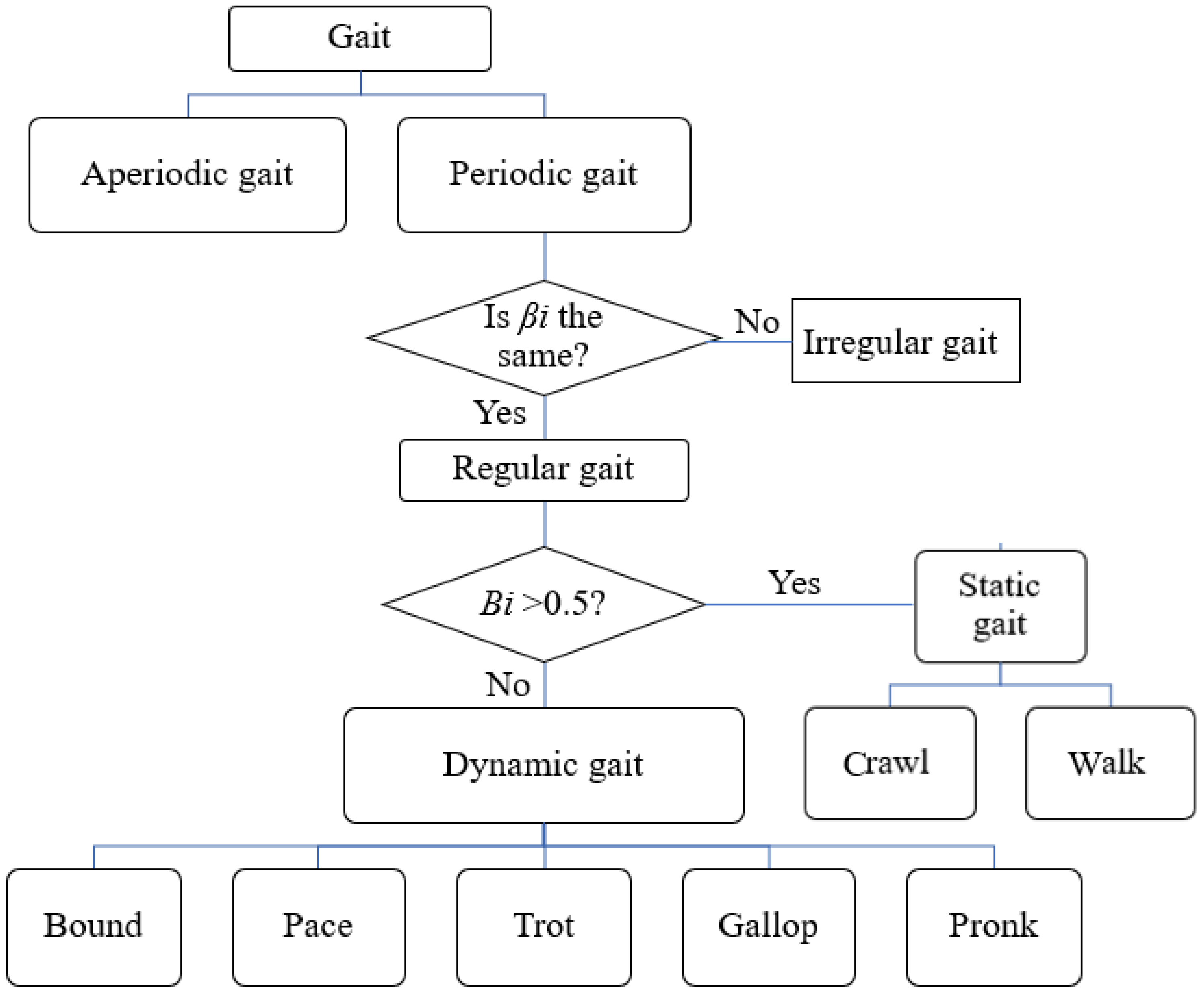
Gait is the sequence of motion of the limbs of a walker (human, animal, robot) in time and space [22]. The movement of a footed robot must depend on gait. There are various gaits in the biological world. Depending on the number of limbs, bipedal, quadrupedal, and hexapodal walking styles are different. The same four-limbed animals, horses, dogs, cats, and other species, walk in different ways. Even the same dog will walk in different ways when facing different terrains. Irregular rough roads and regular flat roads will make bionic-robot dogs choose different ways of walking. From this, it can be seen that there are various ways of walking in the biological world. Scholars have defined the relevant concepts of the gait of a quadruped walker. When the limbs are in contact with the ground, the state of the limbs is the support phase; when the limbs are swinging in the air, the state is the swing phase; the time required for the same limb to reach the same state is the period (T); the gait of the biological dog when three or more limbs are in the landing phase at any time is the static gait; the gait when only two or fewer limbs are in the landing phase at any time is the dynamic gait; the ratio of landing-phase duration to cycle is the duty cycle (β); and the minimum convex polygon formed by the landing points is the support area [23]. The common gaits of quadruped robots are shown in Figure 7.
The duty cycle βi is the ratio of the duration tst of the i-th limb on the ground to the period T. The calculation equation is shown in Equation (20):
β i = t s t T
In the equation, tst represents the duration of the ground phase, and T represents the period.
In addition to the duty cycle βi, another important parameter describing gait is the phase difference φi. The phase difference is defined as the ratio of the difference between the landing time ti of the i-th limb and the landing time t0 of the reference limb and the movement period. The calculation method follows in Equation (21):
φ i = t i t 0 T
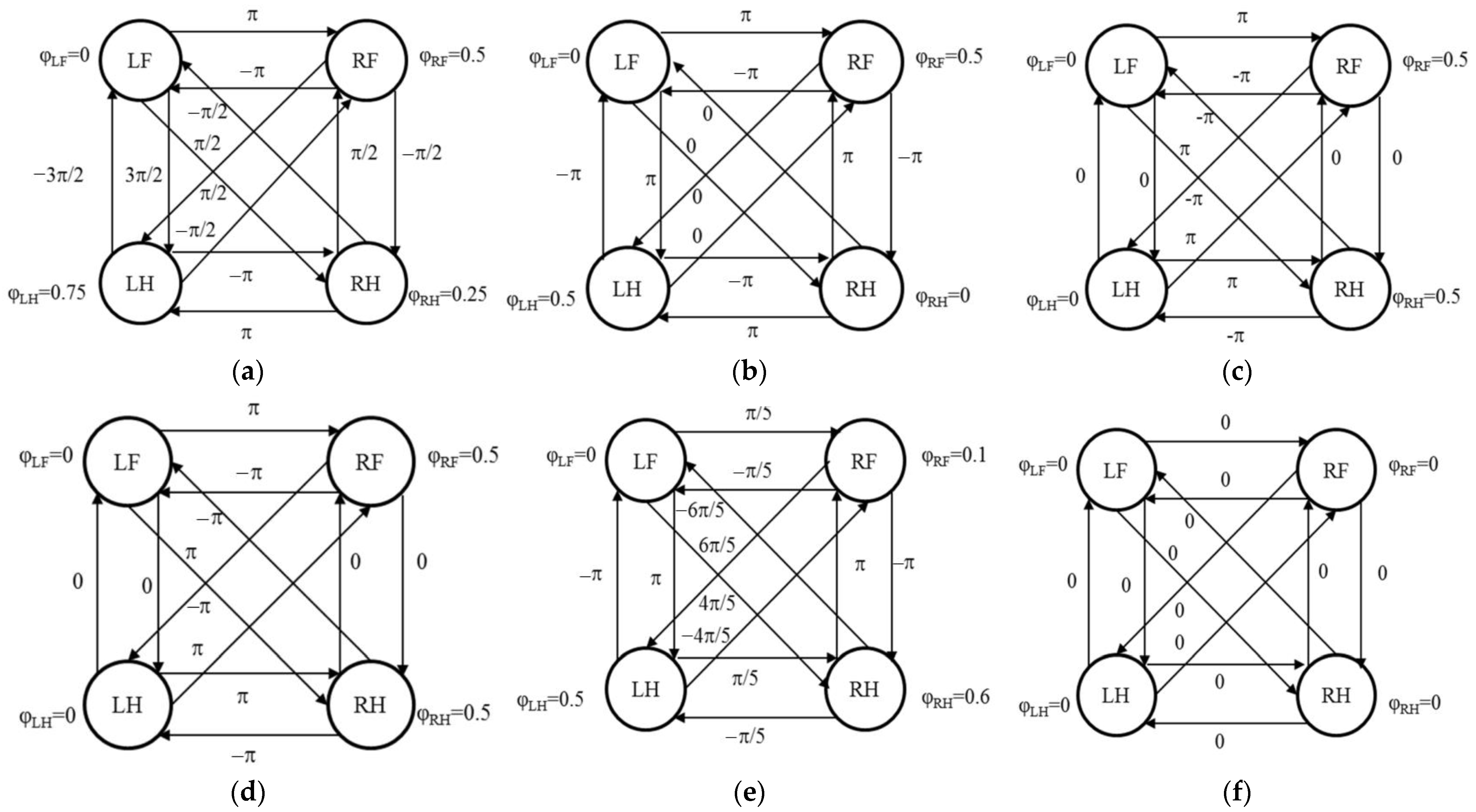
The phase difference φi describes the phase relationship between the limbs, and the response in the gait is the sequence of movements of the limbs. Figure 8 lists the relative relationships between the phases of each limb in several common gaits. In the figure, LF represents the left-front limb. RF represents the right-front limb. LH represents the left-hind limb, and RH represents the right-hind limb, all with the left-front limb as the reference limb, i.e., φLF = 0.
The duty cycle βi and the phase difference φi together describe the gait. The former reflects the speed of the walker’s movement, and the latter reflects the coordination relationship between the limbs. In order to clearly describe the movement speed of the walker, it is also necessary to know the trajectory curve of the foot end of the walker.
When determining the stability of gait, the zero-moment point (ZMP) method is needed. Its definition is shown in Figure 9, where the X-direction is the forward direction of the robot. The ZMP is defined as the intersection point of the extension line of the combined force of gravity and inertial force on the ground, i.e., P in Figure 9. The combined moment of inertial force and gravity at the ZMP is zero, so this point is also known as the zero-moment point. If the ZMP falls within the polygonal support area formed by the foot and ground, the gait is stable. On the contrary, if the ZMP falls outside the support area, the gait is unstable.
In the inertial coordinate system, if the coordinate of the center of gravity is Pc = [xc, yc, zc]T, the mass of the machine is M, the acceleration of gravity is g = [0, 0, −g]T, the coordinate of point P is P = [PX, PY, PZ]T, and the combined force of the ground reaction force on the support point is F, then the torque of F around the origin is as shown in Equation (22):
τ = P × F + τ P
Among them, τp is the torque passing through P.
Equation (23) can be obtained from the momentum theorem and angular momentum theorem:
P ˙ = M g + F L ˙ = P C × M g + τ
Combining Equations (22) and (23), the expression for τp can be obtained as Equation (24):
τ P = L ˙ P C × M g + ( P ˙ M g ) × P
According to the definition of the ZMP, τpx = 0, and τpy = 0, the expression for the ZMP can be obtained as in Equation (25):
x p = M g x c + Z P P ˙ X L ˙ Y M g + P Z y p = M g y c + Z P P ˙ Y L ˙ X M g + P Z
If the quadruped robot is simplified to a mass point, the momentum and angular momentum are as in Equation (26):
P = M P C = M x ˙ C , y ˙ C , z ˙ C T L = P C × M P ˙ C
The coordinate expression of the ZMP is shown in Equation (27):
x P = x C z C z P x ¨ C z ¨ C + g y P = y C z C z P y ¨ C z ¨ C + g
The coordinates of the ZMP can be obtained based on the coordinates of the center of gravity and ground height. When the ZMP falls within the support area, the gait is stable.

3.3.2. Dynamic-Gait Planning

A gait with a duty cycle βi ≤ 0.5 is called a dynamic gait. Dynamic gait is the gait taken by pedestrians when they require a high speed of movement. The planning is mainly divided into two parts. One part is to determine the coordination relationship between the limbs, that is, to determine the duty cycle and phase difference, and the other part is to plan a reasonable foot-trajectory curve.
The coordination relationship between the limbs of a quadruped robot is determined by phase difference and duty cycle. When the movement speed of a biological dog exceeds 6.0 km/h, the gait adopted is the dynamic gait. Firstly, we calculated the gait duty cycle. Figure 10 shows the displacement diagram of the right-hind-limb foot end in the Z-direction at 6.0 km/h, and the diagram shows a period. The displacement change in the Z-direction reflects the state of the limb. When the displacement remains constant, it indicates that the limb is in contact with the ground and in the contact phase. When the displacement changes, it indicates that the limb is swinging in the air and in the swinging phase. By combining the time point of landing in the captured video, the duty cycle β at 6.0 km/h can be calculated, that is, β = 0.75 0.5 1.05 0.5 = 0.455 . Similarly, the duty cycles of 6.5 km/h and 7.0 km/h are 0.417 and 0.420, respectively.
When designing the gait of a bionic-robotic dog, in order to ensure the stability of the dog during high-speed motion, take the duty cycle β = 0.5 to ensure that both limbs are on the ground at all times. The order of swinging the limbs is to swing both the left-front limb and the right-hind limb simultaneously, followed by swinging both the left-hind limb and the right-front limb simultaneously. Using the left-front limb as the reference limb, the phase difference between each limb is as follows: φLF = 0, φRF = 0.5, φLH = 0.5, φRH = 0.
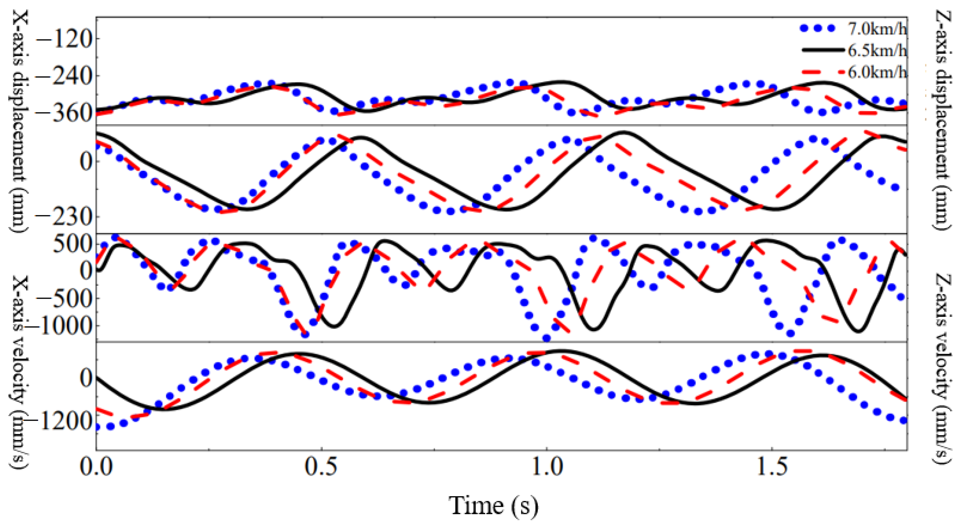
In order to achieve bionic gait, it is necessary to first study the foot-trajectory characteristics of biological dogs during rapid gait. Figure 11 shows the movement of the right-hind-limb foot end relative to the hip during the test of the Labrador dog on a treadmill at speeds of 6.0 km/h, 6.5 km/h, and 7.0 km/h.
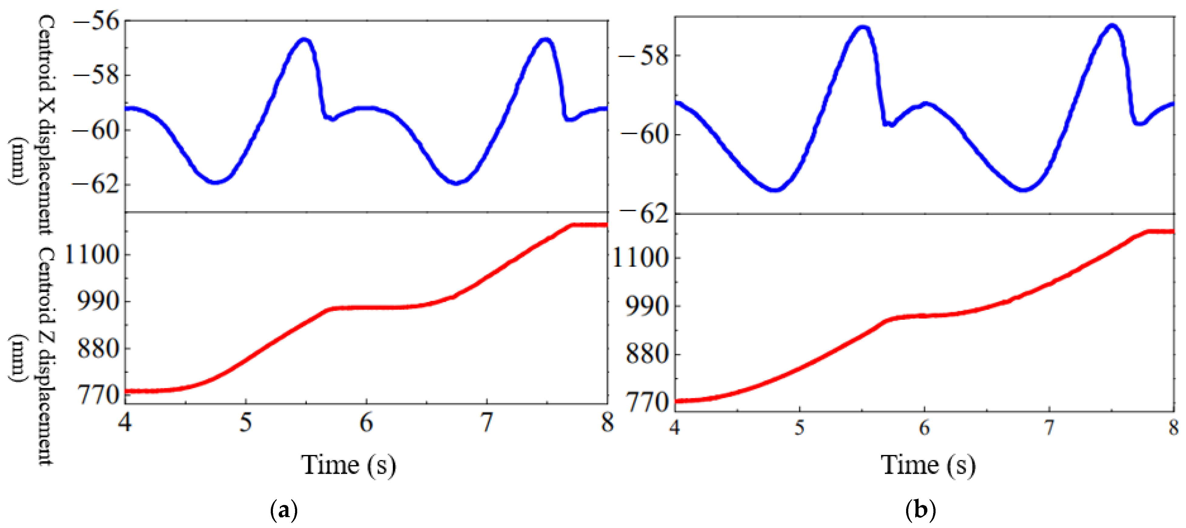
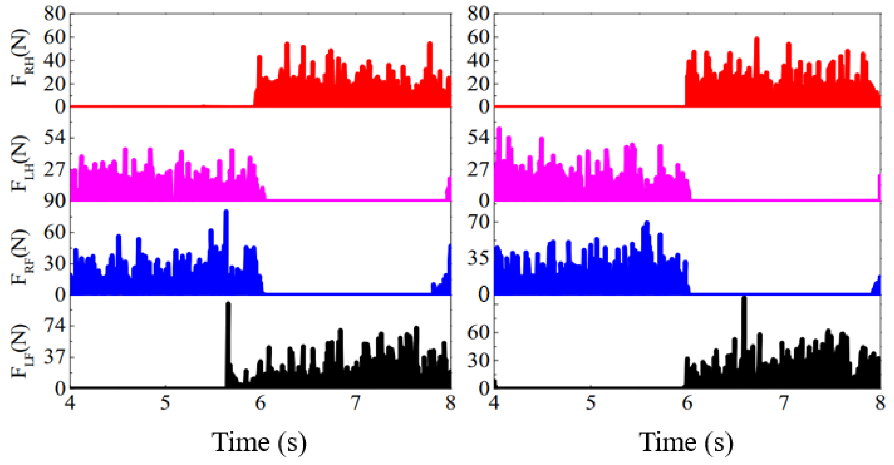
Observations have shown that the foot trajectory of a biological dog can be described in two ways, one in the form of a compound cycloid and the other in the form of a polynomial. This article simulates the cycloid and polynomial foot-trajectory curves separately, and then derives the simulation results data from ADAMS post-processing. Because the bionic-robot dog enters the simulation state from zero when it starts moving in the simulation environment, its position undergoes a sudden change. At the end of the exercise, it suddenly enters the zero position and the position undergoes a sudden change. So, this study selected the second period in the middle to observe its motion, and it compared the two curves in terms of stability and foot-end force. Figure 12 shows the motion of the centroid of a bionic-robotic dog. Figure 13 shows a comparison of foot-end forces between the two trajectories.
From the perspectives of stability and foot force, both trajectory curves have advantages and disadvantages. This study ultimately chose polynomial foot trajectory. On the one hand, stability is the first factor to consider in the overall motion of the machine, and the stability of the polynomial foot trajectory is greater than that of the composite cycloid. On the other hand, although the maximum foot force on the polynomial foot trajectory is slightly greater than that on the cycloidal foot trajectory, the difference is not significant and has little impact on the stability of the bionic-robot dog.

3.3.3. Static-Gait Planning

A gait with a duty cycle βi > 0.5 is called a static gait. Static gait is the gait taken by a pedestrian when the speed requirement is not high. Its planning was also divided into two parts, the coordination relationship between the four limbs and the trajectory curve of the foot ends. To determine the duty cycle and phase difference during static gait, we observed the static-gait movement of the biological dog first. Figure 14 shows the gait of a biological dog at a speed of 3.5 km/h.
When a biological dog moves at low speed, its four limbs are stepped out one by one in sequence, transitioning from having no less than two limbs swinging at any time to having more than two limbs landing on the ground at the same time. Figure 15 shows the displacement of the right-hind limb in the Z-direction at 4.0 km/h, and its duty cycle can be calculated based on the time point of landing in the video, that is, β = 1.15 0.65 1.35 0.65 = 0.74 . Similarly, it can be calculated that the duty cycle at 3.5 km/h was 0.722.
To ensure that three limbs land at any one time, take the duty cycle β = 0.75.
Observing the gait of biological dogs at low speeds, the order of limb swinging used by the Labrador dog was left front–right hind–right front–left hind. Research has found that when a biological dog adopts this limb-swinging sequence, its stability is the greatest, and the gait at this time is called a wave gait. Taking into account stability and the bionics of the robotic dog, this experiment determined the order of swinging the limbs to be the waveform-gait sequence of left front–right hind–right front–left hind. When using a wave gait, the phase difference between the limbs is shown in Equation (28):
φ 2 n 1 = F ( m β ) φ 2 n 1 = F ( φ 2 n 1 + 0.5 )   m = 1 , 2 , n 1 ,   3 2 n β < 1
In the formula, F(x) represents the decimal part of the real number x. 2n + 1 represents the limb on the left side of the body. Because it was a quadruped robot, it had limb 1 and limb 3 from front to back, and the corresponding right limbs were limb 2 and limb 4. Equation (29) can be obtained:
φ 1 = 0 φ 2 = 0.5 φ 3 = β φ 4 = F ( β + 0.5 )
Take β = 0.75, then φ1 = 0, φ2 = 0.5, φ3 = 0.75, and φ4 = 0.25. Follow the order of limb swings 1–4–2–3, with phases increasing by 0.25 in sequence. At this point, the gait is an equal-phase-wave gait, and when the robot walks in this gait, its energy consumption fluctuates minimally.
Comparative analysis showed that the polynomial foot-trajectory curve is better than the cycloid, so the polynomial curve was proposed for the static-gait foot trajectory. In order to plan a reasonable trajectory curve for the bionic foot, this study analyzed the movement of a biological dog’s body relative to the ground during movement. Following the movement of a biological dog, when designing a static landing phase, in order to ensure uniform movement of the body relative to the ground, it was necessary to ensure that the three limbs in the landing phase had the same speed relative to their respective hips. Therefore, a straight-line form was chosen for the landing phase on the X-axis. The curve equation combining straight lines and polynomials was used to describe the foot trajectory, as shown in Equation (30):
X w = X s w = a t 3 + b t 2 + c t + d   ( 0 t < T 4 ) X s t = e t + f   ( T 4 t T ) Z w = Z s w = A t 4 + B t 3 + C t 2 + D t + E   ( 0 t < T 4 ) Z s t = H   ( T 4 t T )
In the equation, sw represents the swinging phase; st represents the landing phase; a, b, c, d, e, f, A, B, C, D, E are undetermined coefficients; and T is the period of motion.
The curve of foot trajectory and velocity variation in static gait is shown in Figure 16.
It can be seen that the foot trajectory composed of polynomials and straight lines was smooth and changes uniformly. For a single limb, it is ensured that during the landing phase, the foot end moves at a uniform speed relative to the hip, ensuring that the body moves at a uniform speed relative to the ground in the overall coordinate system. The position and speed of each limb during the swing phase change continuously without any sudden changes.

3.3.4. Gait-Transition Planning

In the exercise experiments on the biological dog, as the speed of the treadmill increased, the gait of the biological dog quickly changed from adapting to a low-speed static gait to adapting to a high-speed dynamic gait. For bionic-robot dogs, to achieve the transition from static to dynamic gait, the first consideration is overall coordination. To achieve the rapid-transition effect of a biological dog, it is necessary to shorten the time required for gait switching. Based on the above considerations, the bionic-robot dog adopted a method of simultaneously switching the phase of its four limbs and the trajectory of its feet, completing gait switching within half a period. Figure 17 shows the phase-change diagram of the planned transition process. The wireframe represents the state of each limb during gait transition. To the left of the wireframe is a period of static gait. On the right is the gait of two periods. Using the left-front limb as the reference limb, the static gait [0, T/4] was called the static-gait swing phase; [T/4, 2T/4] was the first landing stage; [2T/4, 3T/4] was the second landing stage; and [3T/4, T] was the third landing stage.
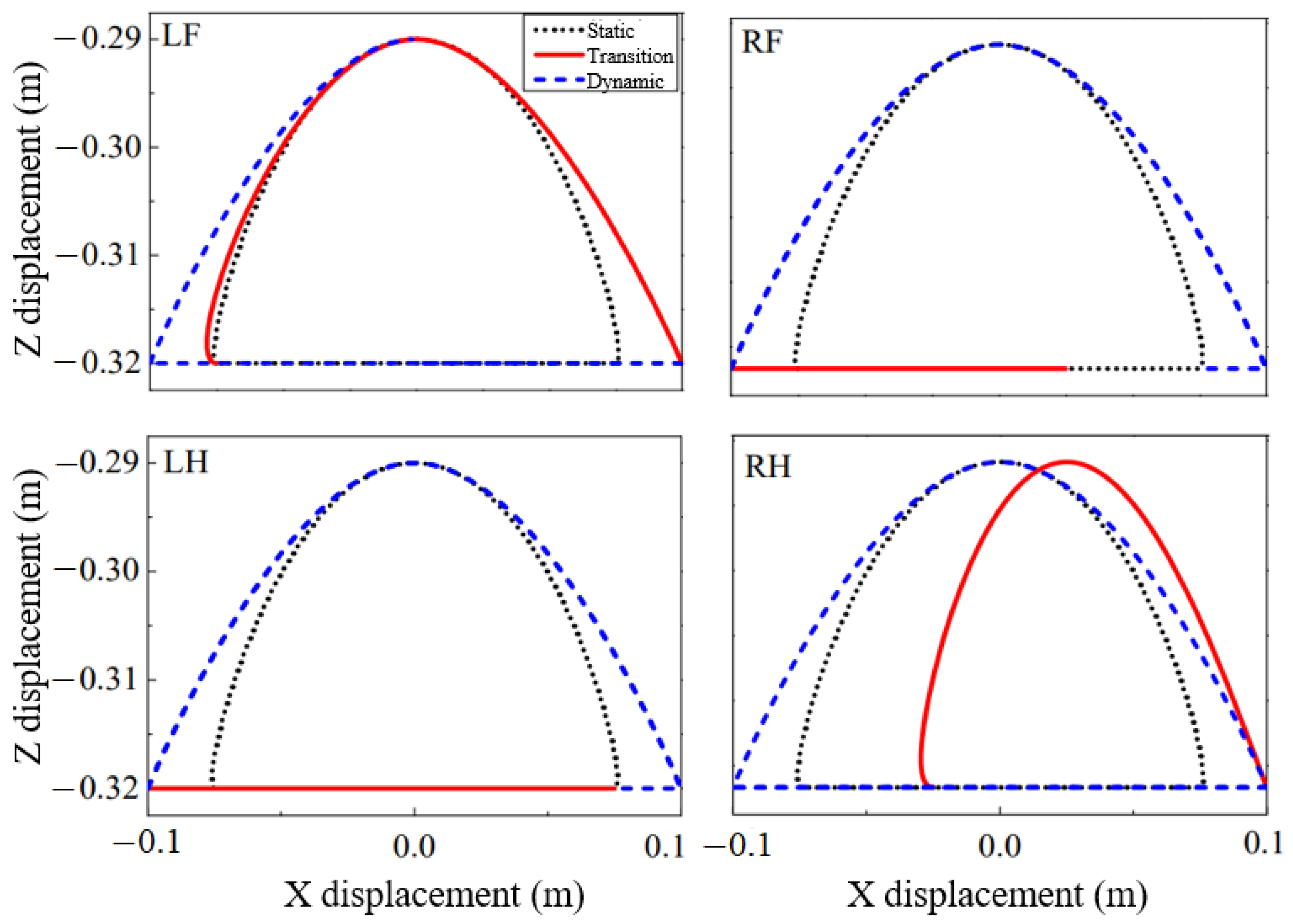
Due to the difference in foot-trajectory curves between static and dynamic gait, the phase-transition process is accompanied by changes in foot-trajectory curves. Because each limb is in a different phase, it is necessary to plan the foot-trajectory transition curves for each of the four limbs separately. Firstly, this study planned the trajectory of the foot end of the right-hind limb. In the hip coordinate system {O1}, planning is on the X and Z axes, respectively, using a cubic polynomial curve on the X-axis and a cycloid on the Z-axis. Assuming that the transition curve equations for the X and Z axes are F(t) and G(t), respectively, and the start time of the static gait is t = 0, in order to ensure that there is no displacement mutation and no velocity mutation during the gait switching process, F(t) and G(t) must meet the following conditions:
F ( 0 ) = X w ( 3 T 4 ) F ( T 2 ) = X t r o t ( T 2 ) F ˙ ( 0 ) = X ˙ w ( 3 T 4 ) F ˙ ( T 2 ) = X ˙ t r o t ( T 2 ) G ( 0 ) = Z w ( 3 T 4 ) G ( T 2 ) = Z t r o t ( T 2 ) G ˙ ( 0 ) = Z ˙ w ( 3 T 4 ) G ˙ ( T 2 ) = Z ˙ t r o t ( T 2 )
The right-hind limb enters the transition gait from the third stage of the static landing phase, with the X-axis entering the dynamic gait through a polynomial curve, and the Z-axis entering the dynamic gait through a cycloid. To achieve rapid transition, the four limbs are transited simultaneously, and the changes in the trajectory of each limb’s foot end are shown in Figure 18.
0–0.5 s: LF and RH enter the swing phase from the third- and second-landing stages of static gait, respectively, while RF and LH enter the transition phase from the first- and swing-landing stages of static gait, respectively.
0.5–1.0 s: Each of the four limbs moves along the transition curve, with LF maintaining its highest point in the Z-axis, RF and LH having no movement in the Z-axis, and RH rising along the curve in the Z-axis.
1.0–1.5 s: Limbs continue to move along their respective transition curves.
1.5–2.0 s: At the end of 2 s, LF and RH simultaneously enter the landing phase of the dynamic gait, and the corresponding RF and LH become the swinging phase of the dynamic gait.
After a 2 s transition process, the bionic robot achieves the transition from static gait to dynamic gait.

4. Experimental Results and Analysis

4.1. Basic Composition of the Experimental System

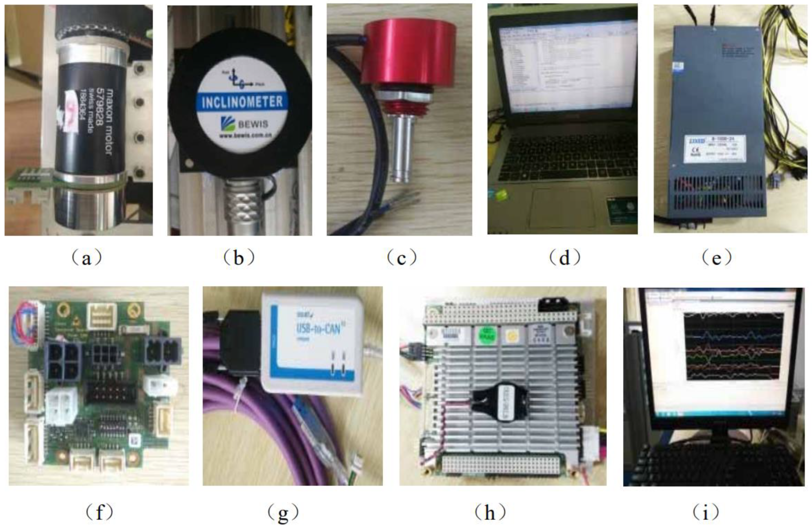
The bionic-robot-dog experimental system consisted of a control part, a robot-dog body, and additional components. Figure 19 shows the physical images of the objects used in the control-system part of the experimental platform. Figure 19a shows the physical image of the EC45 Flat motor. The reducer and motor were integrated, effectively reducing the volume of the motor. Figure 19b shows the inertial-force measurement unit (BW-IMU200-485), which measured the position and attitude of the bionic-robot dog, including the navigation angle, pitch angle, and roll angle, and the angular velocity, angular acceleration, and linear acceleration in the X-direction. Figure 19c shows an angle sensor, model WDA-D22-B. This sensor was installed at the knee and ankle joints of each limb to measure the angle values of the corresponding joints. Figure 19d shows the main control computer. After the experiment started, the main control computer program ran and sent instructions to the driver. Figure 19e shows the S-1000-24 power supply, which provided 24 V DC power for the control system. Figure 19f shows eight EPOS4 drivers used to drive eight motors separately, and which used CAN communication between each driver. Figure 19g shows the USB-CAN interface, which enabled communication with the main control computer and the drivers. Figure 19h shows the control parts stacked by an embedded computer, model PCM-3365, and a data-acquisition card, model PCM-3718. Figure 19i shows the display screen of an embedded computer.
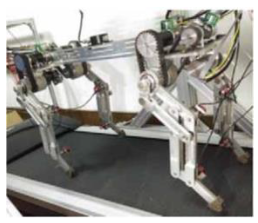
Figure 20 shows the structure of the developed bionic-robot-dog body. The four-limb structure is consistent, with two parallelogram structures on each limb. The connecting part of the front and hind limbs is a rigid back, and in order to increase the strength of the back, a ridge was added to the plate-shaped back. The overall mass of the machine was symmetrical about the two vertical planes where the center of mass was located. Each limb contained two active joints and one passive joint, so each limb had two joints. The two active joints were independently controlled by two motors, and the two motors were coaxial, which can maximize the compact structure of the entire machine. Motor 1 drove the hip joint through the timing belt, and motor 2 drove the knee joint. The eight motors were symmetrically distributed. The eight angle sensors were powered by independent power sources and installed in the corresponding hip and ankle joints. An inertial-force measurement unit was installed at the center of mass of the robot dog.
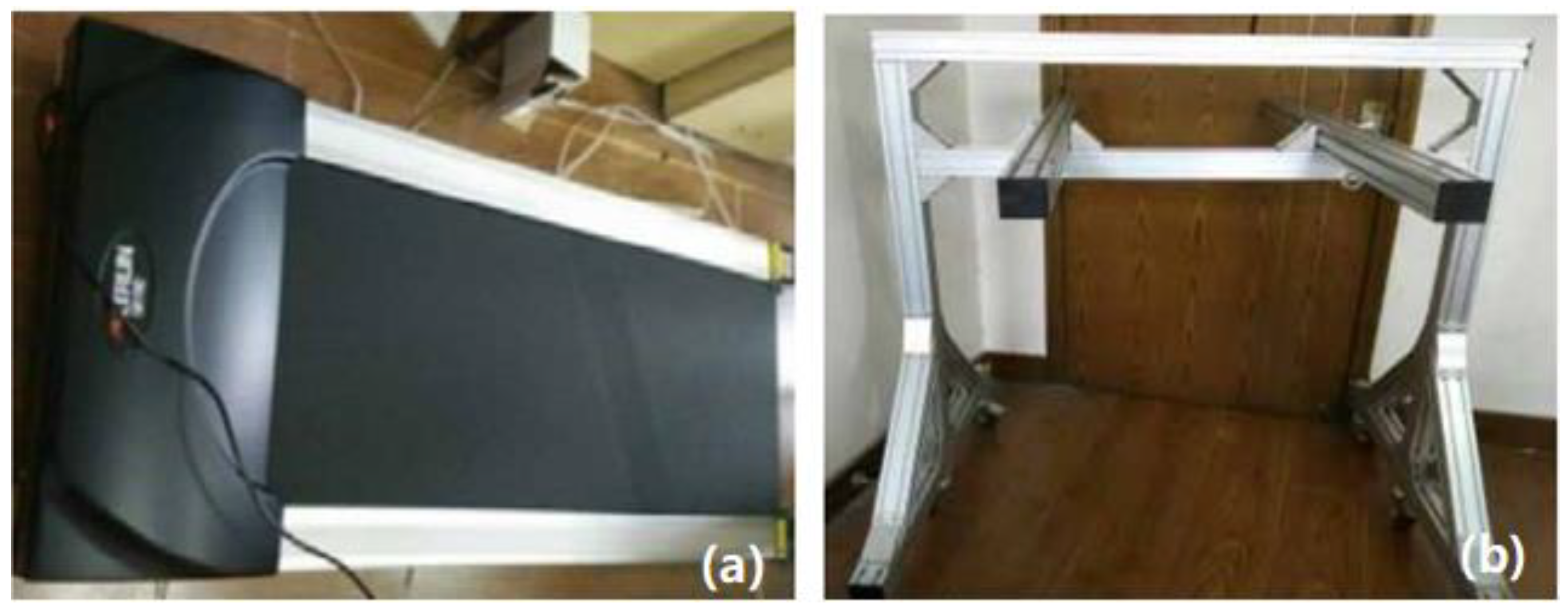
Figure 21 shows the additional components of the experimental system. Figure 21a shows a treadmill, model Officewaalk200, where the robot dog walked, saving experimental space. Figure 21b shows the bracket used to prevent the bionic-robot dog from suddenly tipping over during the experiment; a steel-wire rope was used to connect the robotic dog to the bracket.

4.2. Analysis of Static-Gait Experiment

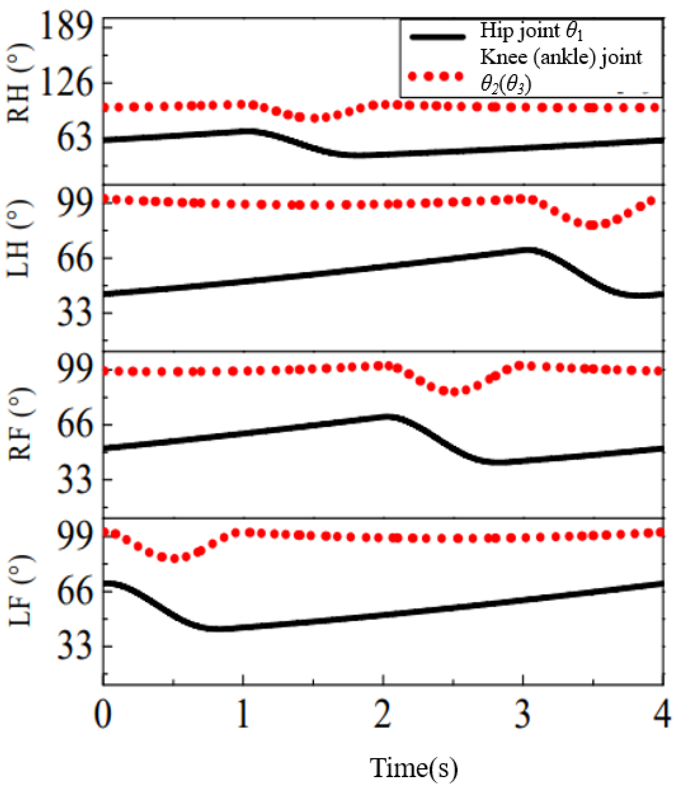
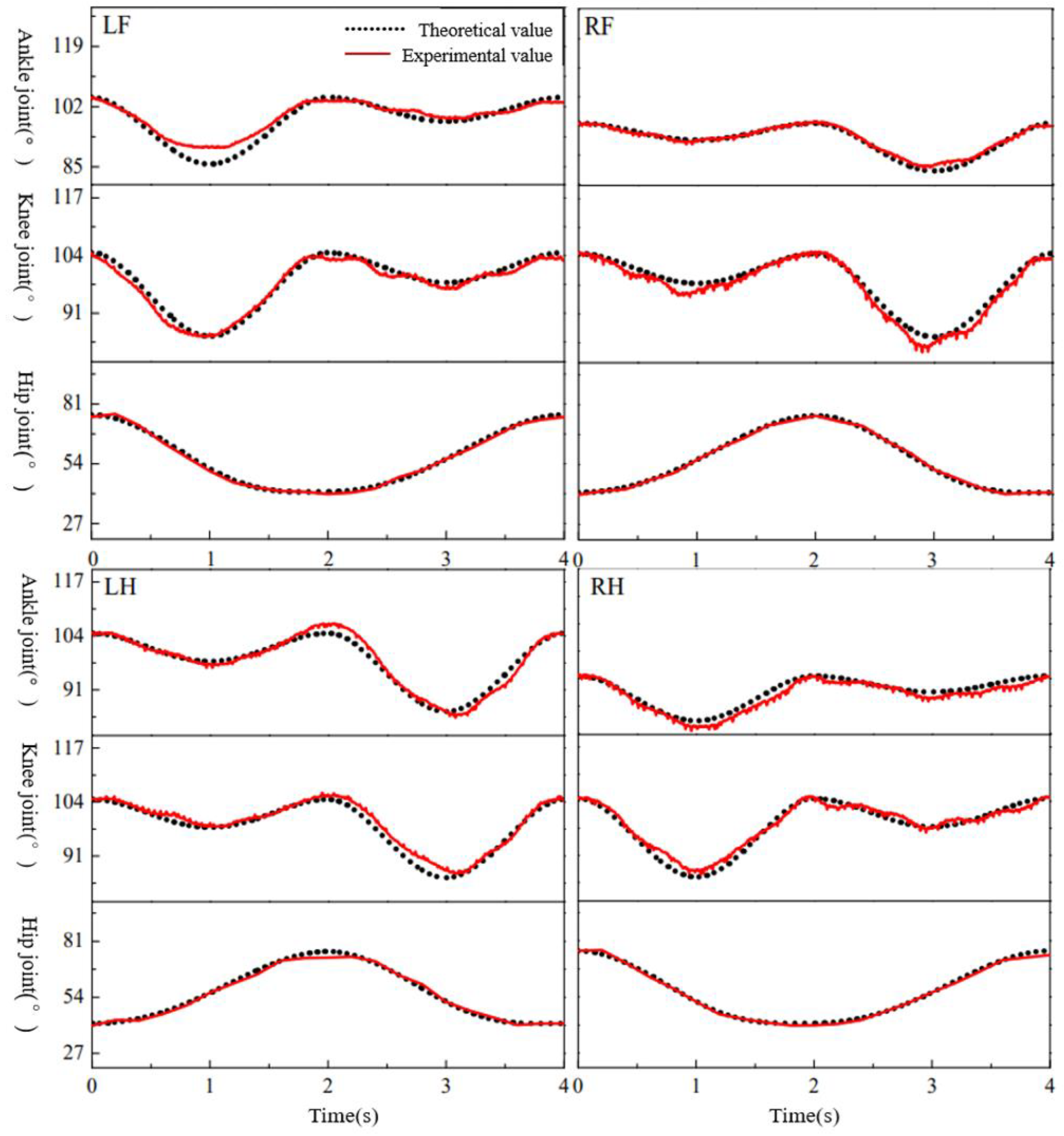
The first step was a static-gait experiment. In the experiment, data from each joint was collected and compared with theoretical values, aiming to achieve the planned theoretical values and achieve the planned gait. The speed tests were 3.5 km/h and 4.0 km/h, respectively. According to the static-gait planning, Figure 22 shows the theoretical curve of the changes in the joint angles of each limb during a period. The variation range of the hip joint was [45°, 70°], and the variation ranges of the knee and ankle joints were [85°, 100°], both within the predetermined range of structural design.
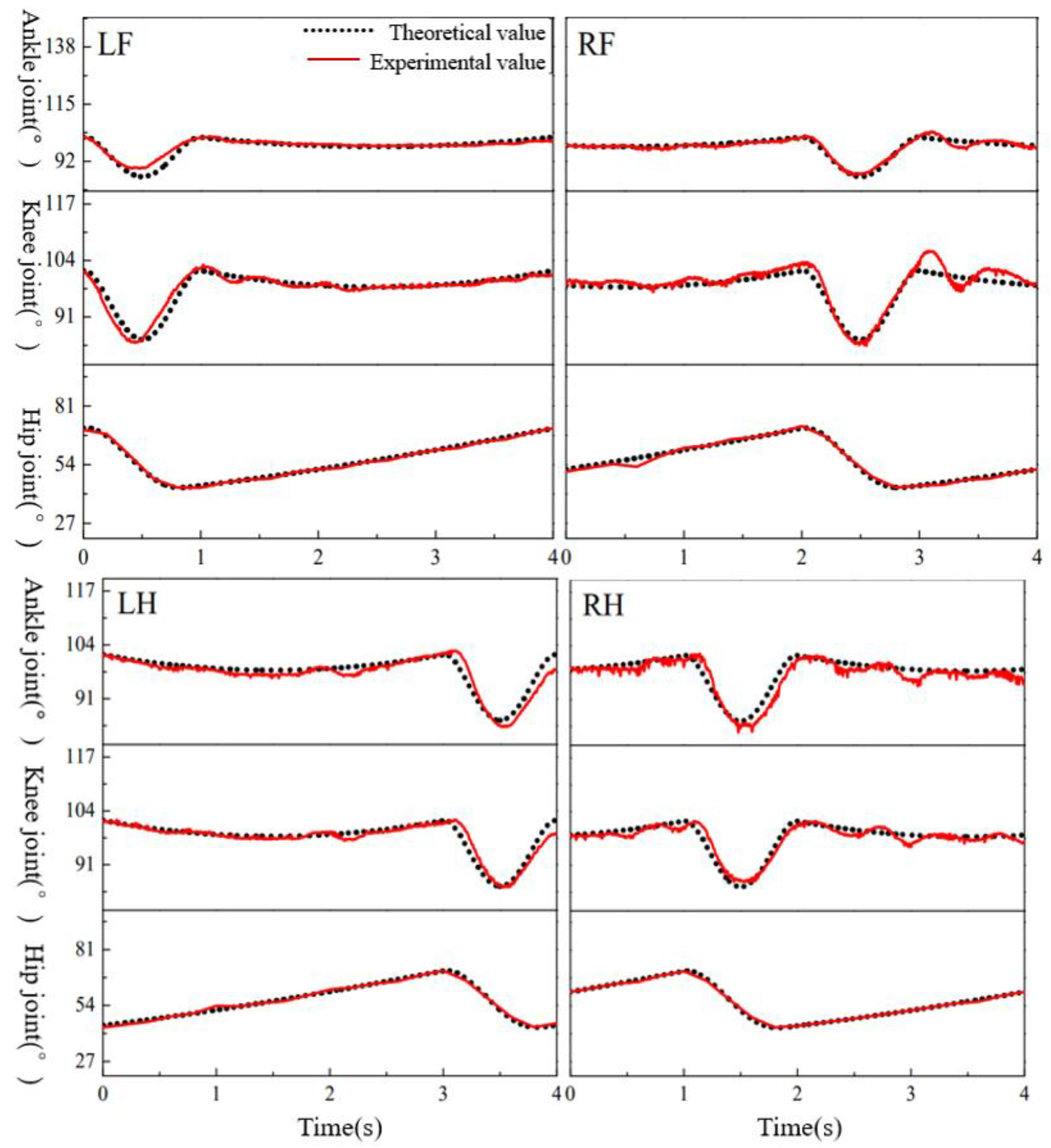
Figure 23 shows the joint angles obtained through data processing based on eight angle sensors and four encoders. The angle sensor measured the angle value between the knee and ankle joints, with a voltage range of [0, 5] (V). The measured angle was [0°, 300°]. If the collected data is a, then the corresponding angle θ is shown in Equation (31):
θ = a 5 × 300
The encoder measured the hip joint angles of the four limbs. Due to the motor deceleration ratio of 81, if the collected data is set to b, then the hip joint angle θ is Equation (32):
θ = b 4096 × 360 × 1 81
The data collected by each sensor can be obtained from Equations (31) and (32) to obtain the angle values of each joint, as shown in Figure 23.
The dotted line in the figure represents the theoretical data of each joint angle, and the solid line represents the experimental data of each joint angle. It can be seen from the figure that the experimental data of the hip joints of each limb was fluctuating near the theoretical data, and the coincidence degree was very high. This was because the angle of the hip joint was processed using the data collected by the encoder, and the error was caused by the performance of the motor, and the error value was very small. Therefore, the rotation angle of the hip joint obtained in the experiment in the figure basically coincided with the theoretical value. The angle data of the knee and ankle joints of the four limbs were collected by the angle sensor. It can be seen from the theoretical analysis that, due to the characteristics of the parallel four-bar mechanism, the angle values of the knee and ankle joints were equal, and the experimental data were consistent with the theoretical analysis. The foot trajectory of the bionic-robot dog was the result of the interaction of various joint angles. The experimental data of the joint angle were close to the theoretical values, which means that the experimental values complied with the planned foot trajectory and realized the planned static gait.
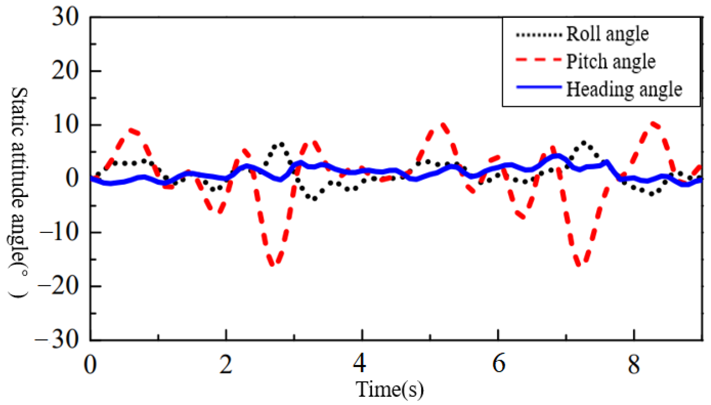
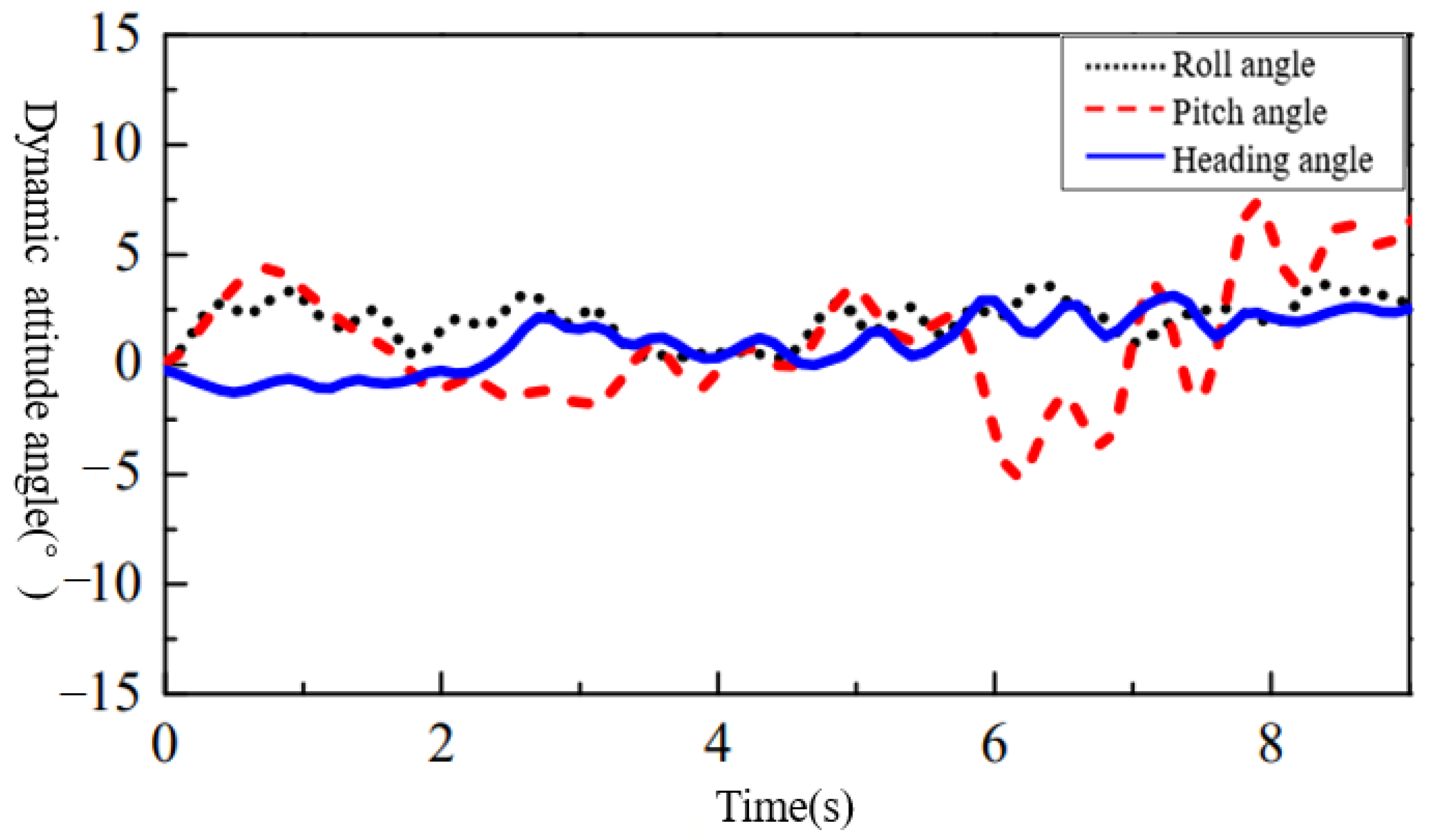
The change in attitude angle during static-gait motion was analyzed. Attitude angle is the angle between the ground coordinate system and the center-of-mass coordinate system, including the heading angle, pitch angle, and roll angle, which reflects the attitude change of the robot during walking. The angle of rotation of the center-of-mass coordinate system around the axis of the vertical direction of the ground coordinate system is the heading angle, and it is positive when the head of the bionic-robot dog is deflected to the right. The angle of rotation around the axis on the right side of the body is the pitch angle, and it is positive when the head of the bionic robot is above the horizontal plane. The angle of rotation around the axis of the forward direction is the roll angle, and it is positive when the right side of the body is tilted upward. Figure 24 is the pose data of the bionic-robot dog collected by the inertial-force measurement unit, which show the changes in pitch angle, roll angle, and heading angle in two cycles.
In Figure 24, it can be seen that the change in the heading angle was the smallest during the walking process of the bionic-robot dog, which was basically maintained at around 0°, which indicated that the bionic robot did not rotate around the vertical direction during the walking process. The variation range of the roll angle was between the heading angle and the pitch angle. At each landing time point, that is, the integer time point in the figure, the roll angle was at the peak or trough, and the corresponding pitch angle was also at the peak or at the same time. The reason for the trough is that the foot end will be impacted by the ground at the moment of landing, and the impact force will have a certain impact on the stability of the robot dog, resulting in changes in its roll angle and pitch angle. The range of the roll angle shown in the diagram was [−5°, 5°], and the range of the pitch angle was [−15°, 10°]. Overall, the robot dog walked relatively smoothly.

4.3. Analysis of Dynamic-Gait Experiment

On the basis of the successful static-gait experiment, a dynamic-gait experiment was conducted, and the experimental platform and steps were consistent with static gait. Compared to the static gait, the bionic-robot dog moved faster, so the treadmill also had a higher speed. As in the planned dynamic gait, the experimental speeds were 6.0 km/h, 6.5 km/h, and 7.0 km/h. When a bionic-robot dog walks in a gait, the motion of both limbs on the diagonal is consistent and is in a swinging or landing phase. Observing the dynamic gait experiment, it was found that the quadruped phase and foot trajectory were basically consistent with the planning. A bionic-robot dog can move steadily on a treadmill.
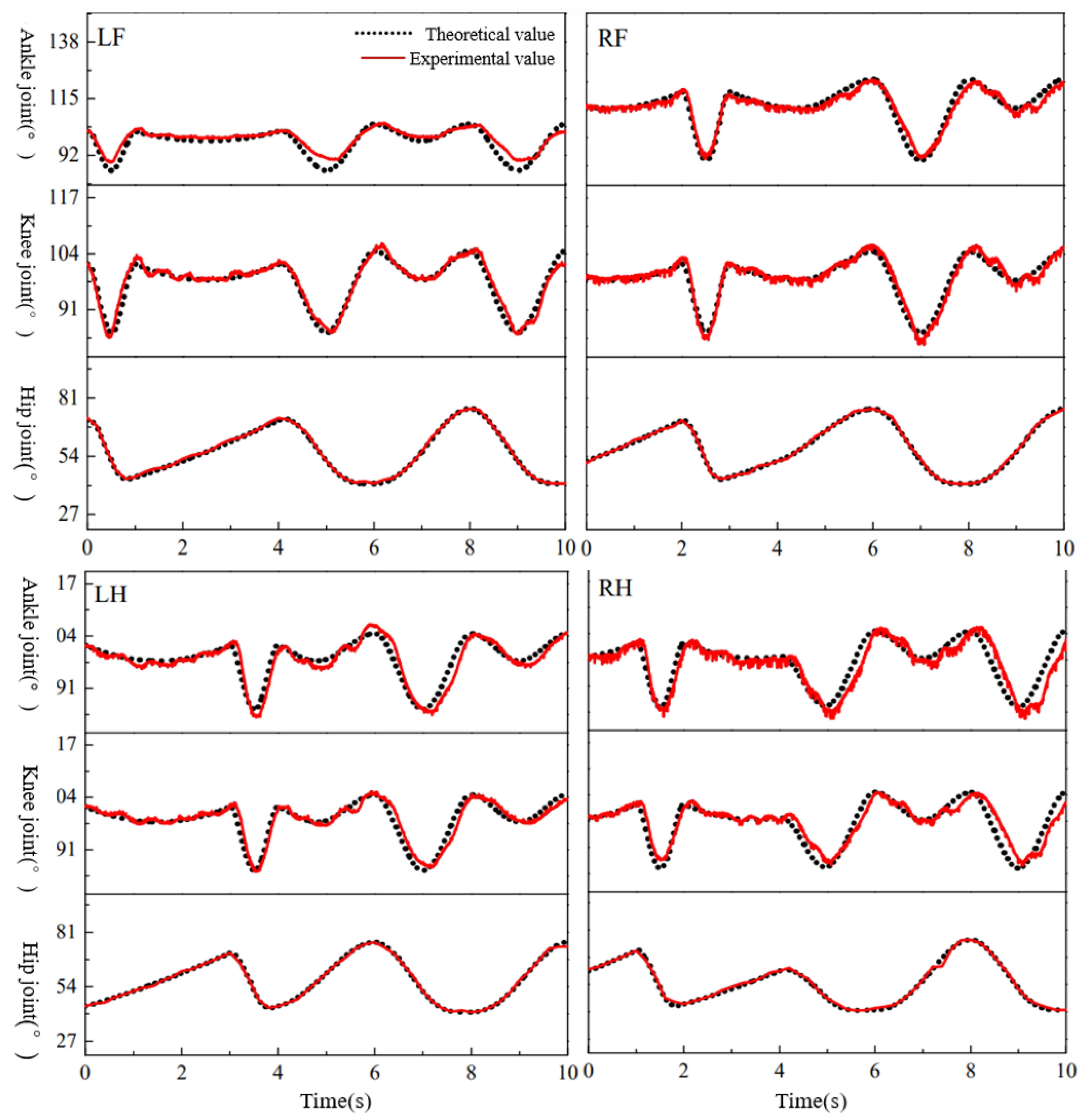
As with static gait, the dynamic-gait experiments also collected the angle values of each joint angle, as well as the attitude angle and displacement of the center of mass through sensors. Figure 25 shows the curves of the ideal joint angle and experimental joint angle plotted based on the experimental data of the dynamic gait. The theoretical values of the hip joints of each limb basically coincided with the experimental values. The experimental values of the knee and ankle joints fluctuated around the theoretical values. The maximum difference between the experimental and theoretical values in the four limbs occurred at the ankle joint of the left-front limb, occurring in the first second of the cycle, when the left-front limb was in the swing phase and its foot reached the highest point of swing. Compared with the static gait, the experimental values of each joint angle in the dynamic gait coincided better with the theoretical values.
Figure 26 shows the changes in attitude angle of the dynamic gait over two periods. The heading angle also had the smallest range of variation, fluctuating only around 0°. The variation range of the roll angle was [0°, 5°], and the variation range of the pitch angle was [−5°, 7°]. Compared with the static gait, the dynamic gait had a smaller range of attitude angle changes. During the dynamic gait, it lands diagonally, creating a torque that can be compensated for by the next landing. Therefore, the change in attitude angle during the dynamic gait was more stable than during the static gait.

4.4. Analysis of Gait-Transition Experiment

On the basis of successful experiments in both the static and dynamic gaits, in order to verify the feasibility of changing gaits, a gait-transition experiment was conducted. The bionic-robot dog first walked in a static gait for one cycle before entering a transition gait. After a 2 s gait transition, it entered a dynamic gait and walked in a dynamic gait for one cycle before ending.
Firstly, we analyzed the changes in each joint angle, as shown in Figure 27. The experimental values of each joint angle fluctuated around the planned theoretical values. The first 4 s were static gait, and the experimental results were consistent with the previous static-gait experiment. The last 4 s showed dynamic gait, which was consistent with the experimental results mentioned earlier. The time period of 4–6 s was a transition gait. At the fifth second, there was a significant difference between the angle value of the left-front-limb ankle joint and the theoretical value.
Figure 28 shows the attitude angle changes of a bionic-robot dog during gait transition. Similarly, the heading angle was basically 0°, and the range of the pitch angle variation was the largest. It was observed for 4–6 s, and the trend of the pitch and roll angles in the fourth to fifth seconds was consistent with the static gait. However, in the fifth to sixth seconds, it no longer changed along the trend line of the static gait, but entered the dynamic gait. During the dynamic gait cycle, i.e., 6–10 s, the changes in pitch angle began to be more chaotic and then tended to become regular. This was because the gait transition had just been completed, and the bionic-robot dog had transitioned from its original static gait to a dynamic gait, with its right-hind limb, which should have been in the landing phase, turning into a swinging phase. In order to adapt to the following gait, the bionic-robot dog needed to adjust its posture, resulting in a brief disorder. After the gait stabilized, the changes in the pitch and roll angles tended to become regular.

5. Conclusions

This paper deeply studied the structural characteristics and motion characteristics of a biological dog, and extracted data from the motion of the biological dog and applied them to the structural design and gait planning of a bionic-robot dog. When planning the foot trajectory of a dynamic gait, the polynomial foot trajectory and the cycloid foot trajectory were compared and analyzed, and the better polynomial foot trajectory was selected according to the simulation results, and its dynamic stability was finally verified. In static gait, the foot-end trajectory takes the form of a combination of polynomial and straight lines, so that the motion of a static gait is similar to that of a biological dog, and so that the bionic-robot dog is not only bionic in the body structure, but also in the form of its motion. Finally, this study built an experimental platform for bionic-robotic dogs and conducted experiments on the three planned gaits. Experiments showed that the three gaits were consistent with the planned motions and that the bionic-robot dog can perform a stable dynamic gait, a static gait, and quickly complete gait transitions.
In this study, the gait planning focused on coordination between the four limbs. Less consideration was given to the coordination between the quadruped’s limbs and its body. The next generation of quadruped robots should focus on this coordination between the limbs and body. Furthermore, when planning the foot trajectory, it is necessary to consider the impact of the foot impact force on the foot trajectory during landing.

Author Contributions

Conceptualization, Z.L. and X.Z.; Methodology, Z.L., Y.S. and X.Z.; Software, Z.L., Y.S., X.Z. and X.P.; Validation, Y.S., X.P. and N.X.; Formal analysis, Z.L., Y.S. and X.P.; Investigation, Z.L., X.P. and N.X.; Resources, Z.L., Y.S. and N.X.; Data curation, Y.S., X.Z. and N.X.; Writing—original draft, Z.L., Y.S., X.Z., X.P. and N.X.; Writing—review and editing, Z.L., Y.S., X.Z. and X.P.; Visualization, X.Z. and N.X.; Supervision, X.P.; Project administration, X.Z. All authors have read and agreed to the published version of the manuscript.

Funding

The authors are thankful for financial support from the Chinese Aeronautical Establishment “Research on Inertial Force-Based Vision Aided Autonomous Navigation System (Aeronautical Science Foundation of China)” (Grant No: 201958068002).

Institutional Review Board Statement

Not applicable.

Informed Consent Statement

Not applicable.

Data Availability Statement

The figures and table used to support the findings of this study are included in the article.

Acknowledgments

The authors would like to express their sincere thanks to the technical staff members who have contributed to this research.

Conflicts of Interest

The authors declare no conflict of interest.

References

  1. Culha, U.; Demir, S.O.; Trimpe, S. Learning of Sub-optimal Gait Controllers for Magnetic Walking Soft Millirobots. Robot Sci. Syst. 2020, 39, 963–972. [Google Scholar]
  2. Berriozabalgoitia, R.; Bidaurrazaga-Letona, I.; Otxoa, E. Overground robotic program preserves gait in people with multiple sclerosis and moderate to severe impairments: A Randomized Controlled Trial. Arch. Phys. Med. Rehabil. 2020, 102, 27–44. [Google Scholar]
  3. Dziubek, W.; Stefańska, M.; Bulińska, K. Effects of Physical Rehabilitation on Spatiotemporal Gait Parameters and Ground Reaction Forces of Patients with Intermittent Claudication. J. Clin. Med. 2020, 9, 2826. [Google Scholar] [CrossRef] [PubMed]
  4. Hagner-Derengowska, M.; Kauny, K.; Kauna, A. Effect of a training program of overground walking on BTS gait parameters in elderly women during single and dual cognitive tasks. Int. J. Rehabil. Res. 2020, 43, 187–202. [Google Scholar] [CrossRef]
  5. Timotius, I.K.; Bieler, L.; Couillard-Despres, S. Combination of Defined CatWalk Gait Parameters for Predictive Locomotion Recovery in Experimental Spinal Cord Injury Rat Models. eNeuro 2021, 8, 1467–1473. [Google Scholar] [CrossRef]
  6. Kowalsky, D.B.; Rebula, J.R.; Ojeda, L.V. Human walking in the real world: Interactions between terrain type, gait parameters, and energy expenditure. PLoS ONE 2021, 16, 192–215. [Google Scholar] [CrossRef]
  7. Bailey, H.; O’Brien, T.D.; Barton, G.J. Walking towards a visually distracting environment does not affect gait kinematics and spatiotemporal parameters of children with cerebral palsy diplimbia. Gait Posture 2021, 90, 11–12. [Google Scholar] [CrossRef]
  8. Lee, J.; Li, L.; Shin, S.Y. Kinematic comparison of single degree-of-freedom robotic gait trainers. Mech. Mach. Theory 2021, 159, 104258. [Google Scholar] [CrossRef]
  9. Agm, A.; Sgrn, A.; Rwm, B. Effect of hippotherapy on walking performance and gait parameters in people with multiple sclerosis—ScienceDirect. Mult. Scler. Relat. Disord. 2020, 41, 10822–10825. [Google Scholar]
  10. Lee, I.; Lee, S.Y.; Ha, S. Alterations of lower extremity function, health-related quality of life, and spatiotemporal gait parameters among individuals with chronic ankle instability. Phys. Ther. Sport 2021, 51, 22–28. [Google Scholar] [CrossRef]
  11. Kunha, A.; Phunopas, A.; Jitviriya, W. Gait Control of A Four-limbged Robot with Fuzzy-PID Controller. Proc. Int. Conf. Artif. Life Robot. 2020, 25, 514–518. [Google Scholar] [CrossRef]
  12. Pea, B.; Gp, A.; Cfa, B. The effect of different dual tasks conditions on gait kinematics and spatio-temporal walking parameters in older adults. Gait Posture 2022, 16, 104–114. [Google Scholar]
  13. Hong, S.H.; Jung, S.Y.; Oh, H.K. Effects of the Immobilization of the Upper Extremities on Spatiotemporal Gait Parameters during Walking in Stroke Patients: A Preliminary Study. BioMed Res. Int. 2020, 24, 6157231. [Google Scholar] [CrossRef] [PubMed]
  14. Ji, M.; Park, H.; Lee, H. Effects of hallux valgus angle on one-limbged stance and gait parameters in young adults: A preliminary study. Phys. Ther. Rehabil. Sci. 2020, 9, 10–17. [Google Scholar] [CrossRef] [Green Version]
  15. Gieysztor, E.; Kowal, M.; Paprocka-Borowicz, M. Gait Parameters in Healthy Preschool and School Children Assessed Using Wireless Inertial forcel Sensor. Sensors 2021, 21, 6423. [Google Scholar] [CrossRef]
  16. Gündemir, O.; Duro, S.; Kaya, D.A. Temporo-spatial and kinetic gait parameters in English setter dogs. Anat. Histol. Embryol. 2020, 49, 763–769. [Google Scholar] [CrossRef]
  17. Vitorio, R.; Hasegawa, N.; Carlson-Kuhta, P. Dual-Task Costs of Quantitative Gait Parameters While Walking and Turning in People with Parkinson’s Disease: Beyond Gait Speed. J. Park. Dis. 2020, 11, 653–664. [Google Scholar] [CrossRef]
  18. Chaubey, V.; Kumar, C.; Kapoor, S. Gait Parameters during Backward Walking in Healthy Elderly: A Comparative Study during Different Types of dual tasks. Eur. J. Mol. Clin. Med. 2021, 36, 260–275. [Google Scholar]
  19. Cherni, Y.; Ballaz, L.; Lemaire, J. Effect of low dose robotic-gait training on walking capacity in children and adolescents with cerebral palsy. Neurophysiol. Clin. Clin. Neurophysiol. 2020, 50, 507–519. [Google Scholar] [CrossRef]
  20. Wegrzyn, Y.; Levi, G.; Livneh, K. Tight coupling of human walking and a four-limbged walking-device inspired by insect six-limbged locomotion. Eng. Res. Express 2020, 2, 036001. [Google Scholar] [CrossRef]
  21. Biswal, P.; Mohanty, P.K. Development of quadruped walking robots: A review. Ain Shams Eng. J. 2021, 12, 2017–2031. [Google Scholar] [CrossRef]
  22. Wan, X.; Yamada, Y. An Acceleration-Based Nonlinear Time-Series Analysis of Effects of Robotic Walkers on Gait Dynamics During Assisted Walking. IEEE Sens. J. 2022, 22, 21188–21196. [Google Scholar] [CrossRef]
  23. Boffa, L.; Sesselmann, A.; Roa, M.A. Emerging Gaits for a Quadrupedal Template Model With Segmented Limbs. J. Mech. Robot. 2023, 15, 031011. [Google Scholar] [CrossRef]
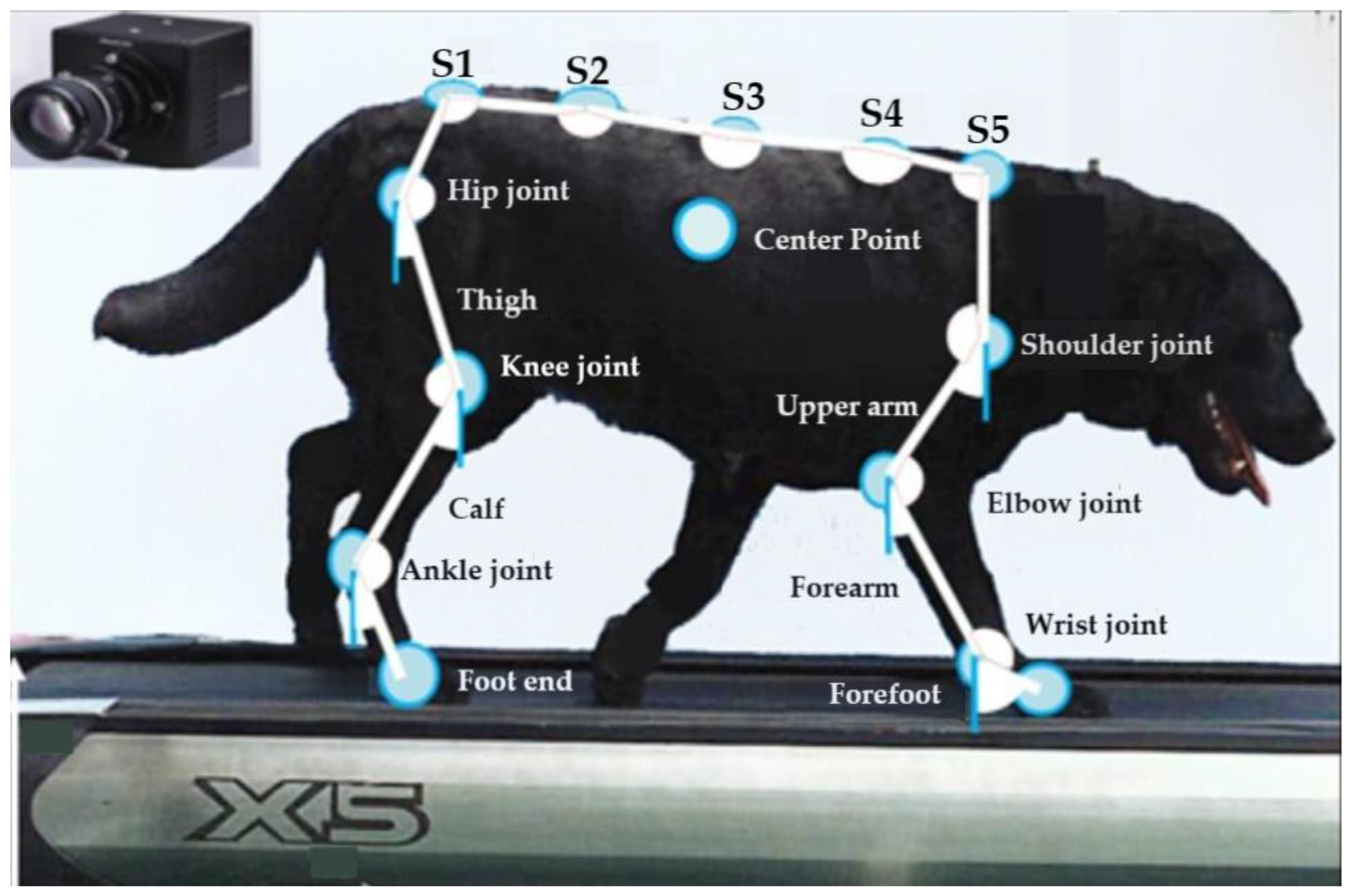
Figure 1. Experimental image of biological-dog motion capture.
Applsci 13 06876 g001
Figure 2. Changes in joint angles when the biological dog moved.
Applsci 13 06876 g002
Figure 3. Mechanical structure of the bionic-robot dog.
Applsci 13 06876 g003
Figure 4. Linkage schematic of the mechanical structure of the bionic-robot dog.
Applsci 13 06876 g004
Figure 5. Structural diagram of one mechanical limb. (a) Structural diagram of one limb; (b) equivalent diagram of one limb’s mechanical structure.
Applsci 13 06876 g005
Figure 6. Motion-analysis diagram of the whole robot mechanism.
Applsci 13 06876 g006
Figure 7. Common gaits of quadruped robots.
Applsci 13 06876 g007
Figure 8. The relative relationships between limb phases in common gaits. (a) Walk. (b) Trot. (c) Pace. (d) Bound. (e) Gallop. (f) Pronk.
Applsci 13 06876 g008
Figure 9. ZMP definition diagram.
Applsci 13 06876 g009
Figure 10. Right-hind-limb Z-axis displacement at 6.0 km/h.
Applsci 13 06876 g010
Figure 11. Movement of the right-hind-limb foot end relative to the hip of the biological dog during dynamic gait.
Applsci 13 06876 g011
Figure 12. Comparison of centroid motion between two trajectories. (a) Cycloid-trajectory centroid displacement; (b) polynomial-trajectory centroid displacement.
Applsci 13 06876 g012
Figure 13. Comparison of foot-end forces between two trajectories.
Applsci 13 06876 g013
Figure 14. Gait of biological dogs at low speed.
Applsci 13 06876 g014
Figure 15. Right-hind-limb Z-axis displacement at 4.0 km/h.
Applsci 13 06876 g015
Figure 16. Foot trajectory and velocity variation in static gait.
Applsci 13 06876 g016
Figure 17. Phase diagram of gait-transition process.
Applsci 13 06876 g017
Figure 18. Changes in the trajectory of each limb during gait transition.
Applsci 13 06876 g018
Figure 19. Control system components. (a) EC45 Flat motor; (b) inertial-force measurement unit; (c) angle sensor; (d) main control computer; (e) S-1000-24 power supply; (f) eight EPOS4 drivers; (g) USB-CAN interface; (h) control parts stacked; (i) display screen of an embedded computer.
Applsci 13 06876 g019
Figure 20. Structure of the developed bionic-robot dog.
Applsci 13 06876 g020
Figure 21. Additional components of the experimental system. (a) treadmill; (b) bracket.
Applsci 13 06876 g021
Figure 22. Theoretical curve of the changes in joint angles of each limb.
Applsci 13 06876 g022
Figure 23. Changes in joint angles in static-gait experiment.
Applsci 13 06876 g023
Figure 24. Changes in attitude angle with static gait.
Applsci 13 06876 g024
Figure 25. Changes in joint angle during dynamic-gait experiments.
Applsci 13 06876 g025
Figure 26. Changes in attitude angle with dynamic gait.
Applsci 13 06876 g026
Figure 27. Changes in joint angle during gait-transition experiments.
Applsci 13 06876 g027
Figure 28. Changes in attitude angle with transition gait.
Applsci 13 06876 g028
Table 1. Parameters of the biological dog and the bionic-robot dog.
ParameterM (kg)l0 (mm)b0 (mm)l1 (mm)l2 (mm)l3 (mm)θ1 (deg)θ2 (deg)
Biological dog25560210130220120[60, 90][90, 130]
Bionic-robot dog20550238135180160[40, 110][80, 150]
Disclaimer/Publisher’s Note: The statements, opinions and data contained in all publications are solely those of the individual author(s) and contributor(s) and not of MDPI and/or the editor(s). MDPI and/or the editor(s) disclaim responsibility for any injury to people or property resulting from any ideas, methods, instructions or products referred to in the content.