Abstract
Goaf-side entry with small coal pillars (GESCPs) has an intrinsic advantage of improving the coal recovery ratio by implementing drifts with a small pillar size next to previous goafs. This technology is increasingly gaining popularity in the longwall mining of underground coal mines in China. This study focuses on understanding the critical condition of the main roof failure above the solid coal side of the goaf-side entry and investigating the key parameters that affect the structural stability of the surrounding rocks for GESCP. Mechanical models of the main roof and multi-layer cracking structures of the side wall of GESCP were established and the limiting equilibrium equation for the structural stability of the surrounding rock was proposed. The characteristics affecting the main parameters of the structural stability of the surrounding rock were analyzed. The research findings suggest that the integrity of the coal side walls plays a major role in maintaining the structural stability of the surrounding rock for GESCP under the given cross-sectional dimensions. Other factors, including the uniform load of overburden, the width of the coal pillar, the length of the roof hanging along the goaf side, and the fracture length in the main roof of the entry side wall, are less important. The key to achieving structural stability of the surrounding rocks for GESCP is to enhance the strength of the supporting coal side walls and, especially, to ensure the integrity of the small coal pillars. These conclusions were verified by engineering practice at the 1252(1) haulage gateway in a Coal Mine in China.
1. Introduction
Entry with a 5–8 m coal pillar excavated along the adjacent goaf side after movement of the overlying strata in longwall mining is called goaf-side entry driving with a small coal pillar (GESCP). Compared to entry driving with a pillar of 20–30 m, using GESCP can improve the coal recovery rate by 6.8–7.4%. The location of the excavated entry is normally in the lower part of the lateral abutment stress induced by nearby coal-face mining, which is beneficial for the maintenance of the goaf-side entry [1,2].
The theory of stability control and the characteristics of the surrounding rock for GESCP in longwall mining has been studied by numerous researchers in recent decades. The reasonable size and long-term stability of the coal pillar is very important for the design of GESCP and the prevention of adjacent goaf disasters [3]. When determining a reasonable coal pillar size and location, some factors, such as the pillar strength [4,5], mining method [6,7], geological condition [8,9], and fracture characteristics of the main roof [10], etc., should be seriously considered. With the mining of the adjacent and present longwall coal faces, the internal stress of the surrounding rock is redistributed [11,12,13]. The inner stress distribution and the possibility of failure characteristics of the small coal pillar is influenced by the dynamic process of mining stress distribution [14,15,16,17,18,19]. In order to prevent the coal pillar from failing and to control the surrounding rock deformation of GESCP, it is necessary to implement reinforcement and support measures [20,21,22,23].
However, most of the current research mainly focuses on stress distribution within a coal pillar, the design of pillar sizes, the main roof fracture structure, the reasonable location of the goaf-side entry, and supporting technologies, etc. Few studies have been conducted on the whole structural stability characteristics of surrounding rocks for GESCP, and the interrelationship between the main roof fracture structure, the coal pillar, and the entry sizes still requires more research, which is of critical importance for optimizing the drivage of GESCP.
In this paper, we focus on the condition of the main roof fracture location above the integrated coal seam, considering the main factors that affect the structural stability of the surrounding rocks for GESCP. Mechanical models were established for the main roof structure and the multi-layer cracking structure of the side walls for GESCP. The limiting equilibrium equation for the structural stability of the surrounding rock for GESCP was solved. The characteristics of the main parameters affecting the structural stability of the surrounding rock were analyzed. The research results were obtained from the Dingji coal mine in China.
2. Mechanical Model of Surrounding Rock for GESCP
After the extraction of the previous longwall panel, the periodic fracture of the main roof above the previous working face resulted in the development of a Voussoir beam structure in the main roof along the direction of the current working face [24]. Simultaneously, a curved triangular block structure, which consisted of a curved triangular key block B, block A above the coal seam, and block C on the goaf, was also formed in the lateral end part of the extracted longwall coal face [25]. After the goaf-side entry was excavated, the key block B maintained stability and balance under the articulated roles of blocks A and C, the support of the caving broken rock in the goaf, and the solid coal side wall. The location of the excavated entry was under key block B and in the stress-decreasing zone of the lateral abutment pressure. The structure of the rock sections surrounding the GESCP is shown in Figure 1.
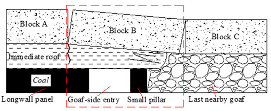
Figure 1.
Schematic section of the surrounding rock of the GESCP (the main roof fracture above the integrated coal side).
Key block B plays a primary role in maintaining the stability of the rock surrounding the GESCP. The load conditions can be simplified, as shown in Figure 2, where F1 is the stress supported by the solid coal side acting on block B, F2 is the stress supported by the small coal pillar acting on block B, F3 is the horizontal stress supported by block A acting on block B, F4 is the horizontal stress supported by block C acting on block B, F5 is the stress supported by waste rock in the goaf, P is the load of overlying strata acting on block B, x0 is the fracture distance from the interface of block B to the coal side of the goaf-side entry, x1 is the width of the small coal pillar, x2 is the length of block B hanging in the goaf, and L and h are the width and height of the goaf-side entry, respectively.
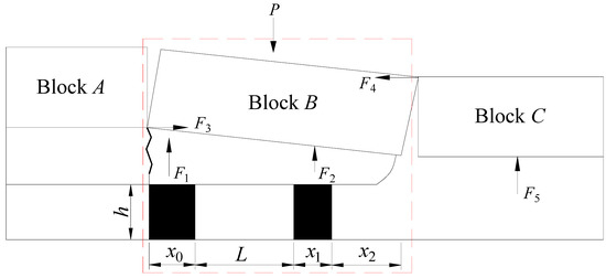
Figure 2.
Mechanical model of the surrounding rock for the GESCP.
2.1. Mechanical Model for the Main Roof Structure for GESCP
It was assumed that only stress in the vertical direction would be considered. The load of the overlying strata P acts on block B and creates a uniform load q1. The supported stress of the solid coal side transfers through the immediate roof and acts on block B, creating the uniform load q2. The supported stress of the small coal pillar transferring through the immediate roof and acting on block B creates the uniform load q3. A simplified mechanical elastic beam model of the main roof structure for GESCP is shown in Figure 3.
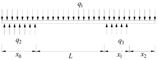
Figure 3.
Mechanical models of the main roof structure for GESCP.
Considering the equilibrium for the main roof in the vertical direction, we obtained the following:
Under the articulated roles of blocks A and C, the left-hand side movement of block B equals zero, so we obtained the following:
After solving Equations (1) and (2), the uniform loads q2 and q3 were derived as:
Then, the support stress from the solid coal side and the small coal pillar were calculated using the above formula.
2.2. Multi-Layer Cracking Mechanical Model of the Side Wall for GESCP
After the development of a goaf-side entry, the original three-dimensional stress acting on the surrounding rock was transformed into two-dimensional stress. The shallow side walls of the goaf-side entry may even bear uniaxial stress. Under the action of compressive stress generated by the roof and floor, a large number of secondary cracks, which extended along the direction of compressive stress, were generated in the shallow coal of the ribs in both the solid coal side as well as the small coal pillar side, as shown in Figure 4. As the cracks increased and joined up, a multi-layer cracking structure finally formed on the coal side [26,27]. In GESCP engineering practice, these sides fail.
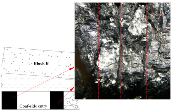
Figure 4.
Site photos of the vertical cracks in the side wall.
The mechanical model of the multi-layer cracking of the side coal was simplified, as shown in Figure 5. We assumed that the multi-layer cracking consisted of thin rectangular plates with a height of h, a width of b, and a thickness of a. The stress between the thin rectangular plates and acted on by the deep coal side was neglected. A 3D planar coordinate system (x, y, z) was used, in which the x-axis corresponds to the height of a thin rectangular plate and the z-axis corresponds to the direction of the excavated entry. The boundary at points x = 0 and x = a bore the uniform load σ, and the boundary at points y = 0 and y = b were free. Owing to the poor integrity of the small coal pillar and the solid coal side, the simple support at both ends and the uniform load σ at the bottom of the thin rectangular plates were simplified, as shown in Figure 5c.
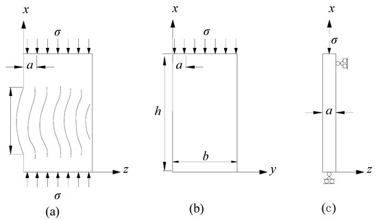
Figure 5.
Mechanical models of the multi-layer cracking of side coal [26]. (a) Cross-section vertical to the entry side; (b) the plane parallel to the axial direction of the roadway; and (c) a conceptualized single layer.
According to the boundary conditions, the thin rectangular plate was buckled into m half-sine wave shapes under the action of the uniform load σ. Its deflection was expressed as:
where A is a constant and m is a positive integer greater than 1.
Using an integral method to solve the differential equations representing the deflection plate, the buckling equilibrium of the thin rectangular plate was expressed as [27]:
where D is the plate stiffness, given by D = Ea3/12(1 − μ2), where E is the elastic modulus of the plate, and μ is the Poisson ratio of the plate.
Considering the boundary conditions at points x = 0 and x = h, substituting Equation (5) into Equation (6) yielded the following:
The boundary conditions for the thin rectangular plate at points y = 0 and y = b were satisfied. So, by solving Equation (7), the collapsing load of the thin rectangular plate σb was derived as follows:
If the size and elastic modulus of the thin rectangular plate are known and m = 1, the buckling shape of the plate is a half-sine wave. The minimum critical collapsing load of the thin rectangular plate (σx)min was derived as follows:
2.3. Limiting Equilibrium Equation for the Structural Stability of the Surrounding Rock for GESCP
After the goaf-side entry was excavated without support, the structure of its surrounding rock maintained stability only when the stresses acting on the solid coal side and small coal pillar were less than (σx)min, i.e., q2 and q3 were both less than (σx)min. These relationships can be expressed as follows:
After solving Equations (10) and (11), we have:
The critical heights of the solid coal side, h1max, and small coal pillar, h2max, for the goaf-side entry without support were expressed as follows:
The critical height of the goaf-side entry for the structural stability of the surrounding rock was the minimum of these two values, i.e.,:
In underground coal mines, the small coal pillar in the structures is firstly destroyed by the large rotating force effect of the lateral hanging structure of block B. Thus, the limiting equilibrium equation for structural stability of the surrounding rock for GESCP with the main roof fracture above the solid coal side was expressed as Equation (15).
3. Key Parameters Affecting GESCP
3.1. Fracture Distance, x0
The relationships between x0 and the critical width and height of the goaf-side entry are shown in Figure 6.
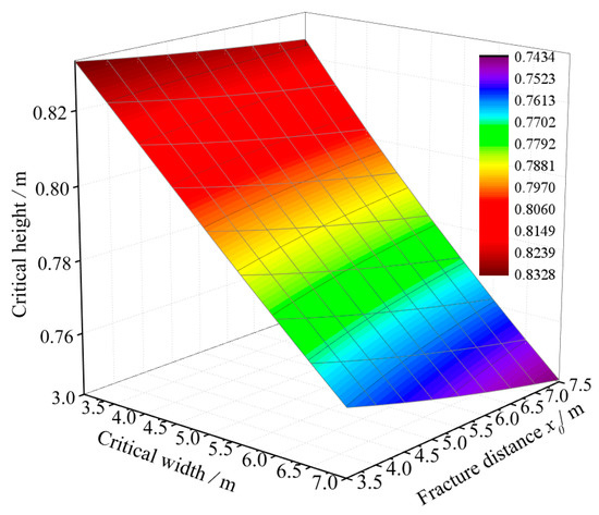
Figure 6.
Relationships between x0, the critical width, and the critical height of the goaf-side entry.
Both the critical height and critical width decreased with increasing fracture distance, x0, for given widths and heights of the goaf-side entry. When the width of the entry was 5 m, the fracture distance increased from 3.5 m to 7.0 m and the critical height correspondingly decreased from 0.8 m to 0.78 m. However, when the height of the goaf-side entry was 0.8 m, the fracture distance increased from 3.5 m to 7.0 m and the critical width decreased from 5.0 m to 4.0 m. The critical width is more sensitive to the fracture distance.
3.2. Width of the Small Coal Pillar, x1
The relationships between x1, the critical width, and the critical height of the goaf-side entry are shown in Figure 7. This indicates that both the critical width and height of the goaf-side entry increases as x1 increases for a certain height or width of the goaf-side entry, respectively. When the width of the goaf-side entry was 5.0 m, the width of the small coal pillar increased from 2.0 m to 3.5 m and the critical height was 0.13 m. When the width of the small coal pillar increased from 4.5 m to 6.0 m, the critical height increased by 0.06 m, i.e., when x1 increased from 2.0 m to 3.5 m, an obvious change in critical width occurred. However, when x1 increased from 3.5 m to 6.0 m, the change in critical width was not obvious. This shows that the small coal pillar had a reasonable width.
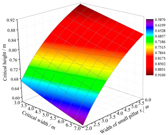
Figure 7.
Relationships between x1, the critical width, and the critical height of the goaf-side entry.
3.3. Hanging Length in the Goaf, x2
The relationships between x2, the critical width, and the critical height of the goaf-side entry are shown in Figure 8. The critical height and width decreased with an increase in the hanging length in the goaf, x2, for a certain width or height of the goaf-side entry, respectively. When the width of entry was 5 m, x2 increased from 0 m to 4.0 m and the critical height decreased from 0.93 m to 0.68 m. In contrast, when the height of the goaf-side entry was 0.8 m, x2 increased from 1.0 m to 2.0 m and the critical width decreased from 7.0 m to 4.0 m. Therefore, the critical width was more sensitive to the hanging length in the goaf.
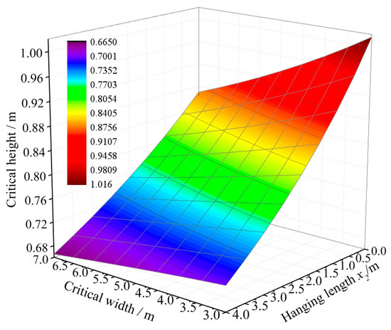
Figure 8.
Relationships between x2, the critical width, and the critical height of the goaf-side entry.
3.4. Overburden Uniform Load, q1
The relationships between overburden uniform load and the critical width and height of the goaf-side entry are shown in Figure 9. The critical height decreased with an increase in the overburden uniform load, q1, for a given width; however, the degree of influence was larger when the overburden uniform load was less than 17.15 MPa. When the width of the goaf-side entry was 5 m, the overburden uniform load increased from 4.9 MPa to 7.35 MPa and the critical height decreased from 1.58 m to 1.29 m. When the buried depth increased from 19.6 MPa to 22.05 MPa, the corresponding decrease in the critical height was just 0.04 m.
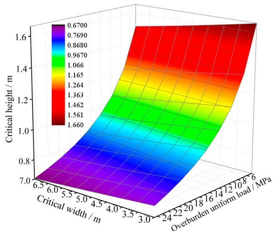
Figure 9.
Relationships between the overburden uniform load (q1), the critical width, and the critical height of the goaf-side entry.
3.5. Thickness of the Thin Rectangular Plate (Integrity of the Coal Side), a
The relationships between the thickness of the thin rectangular plate, a, and the critical width and height of the goaf-side entry are shown in Figure 10. The plate thickness represents the degree of integrity of the coal side. The critical height of the goaf-side entry increased sharply as a increased for a certain width. When the width of the goaf-side entry was 5 m, a increased from 200 m to 300 m and the critical height increased from 0.28 m to 1.45 m. This shows that the integrity of the coal side had the largest impact on the critical width of the goaf-side entry.
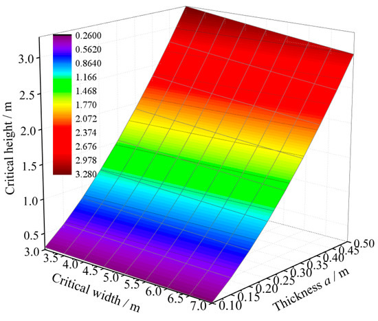
Figure 10.
Relationships between the thickness of the thin rectangular plate (a), the critical width, and the critical height of the goaf-side entry.
From the above analysis, it can be concluded that, for given cross-sectional dimensions of entry, the integrity of the coal side walls plays a predominant role in maintaining the structural stability of the surrounding rock for GESCP. The next most important factor is the depth of the overburden, whereas the width of the coal pillar, the length of the roof hanging along the goaf side, and the fracture length of the main roof on the entry side wall had least impact. This is consistent with underground field observations of the deformation characteristics of rock surrounding a GESCP. Therefore, the key to achieving structural stability of the surrounding rocks for GESCP is to enhance the strengthening supports of the coal side walls and, especially, to ensure the integrity and strength of the small coal pillars.
4. Field Application of Theoretical Results
In order to demonstrate the above analysis, a field study site was selected at the 1252(1) longwall panel of a coal mine in China. The longwall panel extracted the 11-2 coal seam, which had an average thickness of 2.8 m, a dip angle of 2~3°, and an f value of 1.8~2.5. The 1252(1) haulage gateway was excavated along the adjacent goaf side of the 1252(1) longwall panel with a 5 m small coal pillar. The geological borehole profile and the haulage gateway layer in the 1252(1) longwall panel are illustrated in Figure 11.
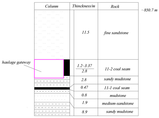
Figure 11.
Geological borehole profile and the haulage gateway layer in the 1252(1) longwall panel.
In order to meet the requirements of large-scale equipment and ventilation, a reasonable size for the haulage gateway was determined to be 4.9 m wide and 3.2 m high. A combined bolt–mesh–cable support was initially chosen, as shown in Figure 12; however, the width of the gateway shrank from 4.9 m to only 3.5 m after 65 days of excavation. Hence, a new effective support control was suggested in order to continue excavation.
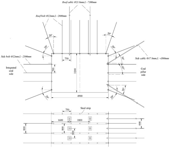
Figure 12.
Sketch of the initial combined bolt–mesh–cable support.
Taking into account the specific geological conditions, combined with field and laboratory test data, the parameters of the surrounding rock structure of the 1252(1) haulage gateway were as follows: L = 4.9 m, q1 = 21.25 MPa, E = 3.97 GPa, μ = 0.28, h = 3.2 m, x0 = 6.0 m, x1 = 5.0 m, and x2 = 0.5 m. After substituting these parameters into Equation (15), the critical thickness of the thin rectangular plate of the small coal pillar in the 1252(1) haulage gateway without support was calculated to be 0.1 m. This meant that alternative supporting methods need to be applied, either by enhancing the integrity and strength of the small coal pillar or by diverting the stress load on it. Therefore, cable beams were introduced in the roof to reduce the abutment pressure on the small coal pillar. Simultaneously, more side cables were added to strengthen the coal pillar and improve its integrity. The revised configuration for the combined bolt–mesh–cable support is shown in Figure 13. In addition, the small coal pillar was also cemented by shotcrete-closed lags 30 m behind the excavating face and was reinforced by grouting using 525# sulfoaluminate cement to further enhance its integrity.
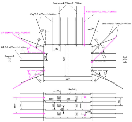
Figure 13.
Sketch of the revised combined bolt–mesh–cable support.
With the new supporting parameters, the deformations of the surrounding rock in the 1252(1) haulage gateway were effectively controlled. The average sidewall-to-sidewall displacement was 225.8 mm and the average roof-to-floor displacement was 385.8 mm. The average subsidence of roof was 57.3 mm. The support effects in the areas 100 m behind the tunnelling face are shown in Figure 14. The section size of the 1252(1) haulage gateway fully met the requirements of the working face. In particular, the integrity and stability of the small coal pillar was significantly improved under the enhanced support of the side cable. The average sidewall-to-sidewall displacement was reduced by about 83.87% compared to the deformation observed under the initial support on the two sides. The revised combined support scheme proposed by analyzing the structural stability and the integrity of the surrounding rock for GESCP was found to be feasible.

Figure 14.
Support effects in the haulage gateway.
Based on the analysis of the structural stability and the integrity of the surrounding rock for GESCP, the surrounding rock of the 1252(1) haulage gateway was controlled by strengthening support. More research about the structural stability of the GESCP should be studied in the future. The possibility of implementing stress optimization control technologies, such as pre-split blasting technology or hydraulic fracturing technology, could be considered to control the fracture location and hanging length in the goaf of block B. This approach can reduce the internal stress on the coal pillar caused by the rotary subsidence of block B. Backfilling mining technology could also be considered as a means of reducing the mining stress on the working face, thereby contributing to the long-term stability of the surrounding rock for GESCP [28,29,30].
5. Conclusions
This work focuses on the condition of the main roof fracture location above the solid coal side, considering the main factors that affect the structural stability of the surrounding rocks for GESCP. Mechanical models of the main roof structure and the muti-layer cracking structure of the side wall of the GESCP were established, and a limiting equilibrium equation for the structural stability of the rock surrounding the GESCP was proposed.
Based on the proposed equation, the characteristics of the main factors affecting the structural stability of the surrounding rock were analyzed. The results indicated that the integrity of the coal side walls was the main factor affecting the structural stability of the surrounding rock for GESCP, with certain cross-sectional dimensions of entry. The second most important factor was the overburden uniform load. Other factors, including the width of the coal pillar, the length of roof hanging along the goaf side, and the fracture length of the main roof in the entry side wall, had the least impact.
We propose that the key to achieving structural stability of the surrounding rocks for GESCP is to enhance the strength of the supporting coal side walls and to ensure the integrity of the small coal pillar. The proposed method was demonstrated to guide the design of supporting structures at the haulage gateway in the 1252(1) longwall panel in a coal mine.
Author Contributions
Conceptualization, Y.Z.; methodology, Y.Z. and Z.X.; software, Z.X.; validation, Y.Z. and Y.Z.; investigation, Y.Z.; data curation, Y.Z.; writing—original draft preparation, Y.Z.; project administration, Y.Z.; funding acquisition, Y.Z. All authors have read and agreed to the published version of the manuscript.
Funding
This work was supported by the National Natural Science Foundation of China (Grant No. 52274146).
Institutional Review Board Statement
Not applicable.
Informed Consent Statement
Not applicable.
Data Availability Statement
Data are contained within the article. Further inquiries can be directed to the corresponding authors.
Conflicts of Interest
The authors declare no conflict of interest.
References
- Bai, J.B.; Hou, C.J.; Huang, H.F. Numerical simulation study on stability of narrow coal pillar of roadway driving along goaf. China J. Rock Mech. Eng. 2004, 23, 3475–3479. [Google Scholar]
- Zheng, X.G.; Yao, Z.G.; Zhang, N. Stress distribution of coal pillar with gob-side entry driving in the process of excavation & mining. J. Min. Saf. Eng. 2012, 29, 459–465. [Google Scholar]
- Najafi, M.; Jalali, S.E.; Yarahmadi Bafghi, A.R.; Sereshki, F. Prediction of the confidence interval for stability analysis of chain pillars in coal mines. Saf. Sci. 2011, 49, 651–657. [Google Scholar] [CrossRef]
- Mohan, G.M.; Sheorey, P.R.; Kushwaha, A. Numerical estimation of pillar strength in coal mines. Int. J. Rock Mech. Min. Sci. 2001, 38, 1185–1192. [Google Scholar] [CrossRef]
- Ghasemi, E.; Ataei, M.; Shahriar, K. An intelligent approach to predict pillar sizing in designing room and pillar coal mines. Int. J. Rock Mech. Min. Sci. 2014, 65 Pt 2, 86–95. [Google Scholar] [CrossRef]
- Recio-Gordo, D.; Jimenez, R. A probabilistic extension to the empirical ALPS and ARMPS systems for coal pillar design. Int. J. Rock Mech. Min. Sci. 2012, 52, 181–187. [Google Scholar] [CrossRef]
- Jiang, L.S.; Zhang, P.P.; Chen, L.J.; Hao, Z.; Sainoki, A.; Mitri, H.S.; Wang, Q.B. Numerical Approach for Goaf-Side Entry Layout and Yield Pillar Design in Fractured Ground Conditions. Rock Mech. Rock Eng. 2017, 50, 3049–3071. [Google Scholar] [CrossRef]
- Zhang, K.X. Determining the reasonable width of chain pillar of deep coal seams roadway driving along next goaf. J. China Coal Soc. 2011, 36 (Suppl. S1), 28–35. [Google Scholar]
- Chen, S.J.; Guo, W.J.; Zhou, H.; Shen, B.T.; Liu, J.B. Field investigation of long-term bearing capacity of strip coal pillars. Int. J. Rock Mech. Min. Sci. 2014, 70, 109–114. [Google Scholar] [CrossRef]
- Li, X.H.; Zhang, N.; Hou, C.J. Rational Position Determination Roadway Driving Along Next Goaf for Fully-Mechanized Top-Coal Caving Mining. J. China Univ. Min. Technol. 2006, 29, 186–189. [Google Scholar]
- Dychkovskyi, R.; Shavarskyi, I.; Saik, P.; Lozynskyi, V.; Falshtynskyi, V.; Cabana, E. Research into stress-strain state of the rock mass condition in the process of the operation of double-unit longwalls. Min. Miner. Depos. 2020, 14, 85–94. [Google Scholar] [CrossRef]
- Vu, T.T. Solutions to prevent face spall and roof falling in fully mechanized longwall at underground mines, Vietnam. Min. Miner. Depos. 2022, 16, 127–134. [Google Scholar] [CrossRef]
- Shavarskyi, I.; Falshtynskyi, V.; Dychkovskyi, R.; Akimov, O.; Sala, D.; Buketov, V. Management of the longwall face advance on the stress-strain state of rock mass. Min. Miner. Depos. 2022, 16, 78–85. [Google Scholar] [CrossRef]
- Wang, H.W.; Jiang, Y.D.; Zhao, Y.X.; Zhu, J.; Liu, S. Numerical Investigation of the Dynamic Mechanical State of a Coal Pillar During Longwall Mining Panel Extraction. Rock Mech. Rock Eng. 2013, 46, 1211–1221. [Google Scholar] [CrossRef]
- Shabanimashcool, M.; Li, C.C. A numerical study of stress changes in barrier pillars and a border area in a longwall coal mine. Int. J. Coal Geol. 2013, 106, 39–47. [Google Scholar] [CrossRef]
- Ju, M.H.; Li, X.H.; Yao, Q.L.; Li, D.W.; Chong, Z.H.; Zhou, J. Numerical investigation into effect of rear barrier pillar on stress distribution around a longwall face. J. Cent. South Univ. 2015, 22, 4372–4384. [Google Scholar] [CrossRef]
- Teng, F.; Yu, M.G.; Chao, J.K.; Ma, Z.H. Coal Pillar’s Breaking and Fracture Development Mechanism and Numerical Simulation. Therm. Sci. 2022, 26, 2439–2446. [Google Scholar] [CrossRef]
- Han, P.H.; Zhang, C.; Wang, W. Faulure analysis of coal pillar and gateroads in longwall faces under the mining-water invasion coupling effect. Eng. Fail. Anal. 2022, 131, 105912. [Google Scholar] [CrossRef]
- Xie, P.S.; Wu, Y.P. Deformation and Failure Mechanisms and Support Structure Technologies for Goaf-Side Entries in Steep Multiple Seam Mining Disturbances. Arch. Min. Sci. 2019, 64, 561–574. [Google Scholar]
- Zhang, Y.; Wan, Z.J.; Li, F.C.; Zhou, C.B.; Zhang, B.; Guo, F.; Zhu, C.T. Stability of coal pillar in gob-side entry driving under unstable overlying strata and its coupling support control technique. Int. J. Min. Sci. Technol. 2013, 23, 193–199. [Google Scholar] [CrossRef]
- Yang, R.S.; Zhu, Y.; Li, Y.L.; Li, W.Y.; Lin, H. Coal pillar size design and surrounding rock control techniques in deep longwall entry. Arab. J. Geosci. 2020, 13, 453. [Google Scholar] [CrossRef]
- Yu, Y.; Bai, J.B.; Wang, X.Y.; Zhang, L.Y. Control of the Surrounding Rock of a Goaf-Side Entry Driving Heading Mining Face. Sustainability 2020, 12, 2623. [Google Scholar] [CrossRef]
- Li, L.S.; Qian, D.Y.; Yang, X.G.; Jiao, H.X. Pressure Relief and Bolt Grouting Reinforcement and Width Optimization of Narrow Coal Pillar for Goaf-Side Entry Driving in Deep Thick Coal Seam: A Case Study. Minerals 2022, 12, 1292. [Google Scholar] [CrossRef]
- Qian, M.G.; Shi, P.W. Mining Pressure and Strata Control; China University of Mining and Technology Press: Xuzhou, China, 2003. [Google Scholar]
- Hou, C.J.; Li, X.H. Stability principle of big and small structures of rock surrounding roadway driven along goaf in fully mechanized top coal caving face. J. China Coal Soc. 2001, 26, 1–7. [Google Scholar]
- Li, Q.; Yang, Q.; Luan, M.T.; Jia, J.C. Study of curved wing crack path by theory and testing methods. Rock Soil Mech. 2010, 31, 345–349. [Google Scholar]
- Zhang, X.C.; Miao, X.X.; Yang, T.Q. The Layer-crack-plate model and testing study of the rockburst in mines. Chin. J. Rock Mech. Eng. 1999, 18, 507–511. [Google Scholar]
- Smoliński, A.; Malashkevych, D.; Petlovanyi, M.; Rysbekov, K.; Lozynskyi, V.; Sai, K. Research into Impact of Leaving Waste Rocks in the Mined-Out Space on the Geomechanical State of the Rock Mass Surrounding the Longwall Face. Energies 2022, 15, 9522. [Google Scholar] [CrossRef]
- Malashkevych, D.; Petlovanyi, M.; Sai, K.; Zubko, S. Research into the coal quality with a new selective mining technology of the waste rock accumulation in the mined-out area. Min. Miner. Depos. 2022, 16, 103–114. [Google Scholar] [CrossRef]
- Chang, Q.L.; Yao, X.J.; Yuan, C.L.; Leng, Q.; Wu, H. Investigation on Failure Characteristics of Coal Seam Floor in Paste Filling Working Face. Geofluids 2021, 2021, 1808571. [Google Scholar] [CrossRef]


Disclaimer/Publisher’s Note: The statements, opinions and data contained in all publications are solely those of the individual author(s) and contributor(s) and not of MDPI and/or the editor(s). MDPI and/or the editor(s) disclaim responsibility for any injury to people or property resulting from any ideas, methods, instructions or products referred to in the content. |
© 2023 by the authors. Licensee MDPI, Basel, Switzerland. This article is an open access article distributed under the terms and conditions of the Creative Commons Attribution (CC BY) license (https://creativecommons.org/licenses/by/4.0/).