Abstract
This paper is focused on the experimental wear characterization of an electromagnetic braking system used for helicopters. The characterization was performed through the evaluation of some monitoring parameters during endurance tests on a test bench and through the visual analysis of the worn surfaces after the tests. The monitoring parameters were the engagement threshold voltage, the release threshold voltage, the inductance, and the braking torque, which are directly correlated with the wear progress. The visual analysis allowed the assessment of the wear extent and the distribution of wear particles at the interfaces. The test performed on the initial base configuration, having ten springs and carbon fibers as friction materials, demonstrated that the braking system had insufficient durability in terms of actuation cycles. The results allowed the design of two new configurations based on different brake architectures and on different friction pairs. One of the new configurations was based on a reduction in the number of springs (eight-spring configuration), and the second one was based on the employment of a different friction material (NAO configuration). Both of these optimized configurations showed enhanced durability and wear resistance, but only the second one showed sufficient durability with respect to the requirements and was defined as acceptable. The final results showed a durability of 3000 actuation cycles for the base configuration, 4385 for the eight-spring configuration, and 35,223 for the NAO configuration. Nevertheless, the analysis of results allowed the cause of the wear phenomena to be studied and eventual further improvements in the system to be suggested.
1. Introduction
Electromagnetic brakes are commonly employed in many industrial, medical, aeronautical, and military applications and even in robotics [1].
In particular, aeronautic electromagnetic brakes are key components of the landing gear of aircraft, which is considered one of the most critical systems for flight safety [2], as almost 60% of failures occur during landing and take-off operations [3].
Catastrophic malfunctions can occur in landing gear and its components as they are subjected to high inertial, impulsive, and cyclic loads [4], and for this reason, the dynamic characterization, design, testing, and maintenance of aeronautic components and braking systems are crucial operations to guarantee flight safety [5,6,7].
Aeronautic brakes have various functions, such as, first of all, the role of generating the required stopping torque under various service conditions through proper friction pairs, but they also serve as heat sinks, maintaining a low temperature by absorbing kinetic energy, and as structural elements to transfer the torque to the tires [8].
Designing electromagnetic braking systems requires a multidisciplinary approach, as the mechanical aspects, including tribological issues, must be combined with electromagnetic [9], structural, and thermal issues [10,11], but the literature includes few studies focused on their overall behavior and design issues [12]. In addition, most of the tribological studies about brakes have focused on braking systems that are not for aeronautical applications. Some works have aimed at analyzing the squealing of brakes, with the aim of reducing this effect by using theoretical and experimental approaches [13,14,15]. Some other works have specifically aimed at studying the contact mechanics and wear behavior of the brakes [16,17,18].
From a tribological point of view, electromagnetic brakes for aircraft must be developed with high-efficiency friction materials, which must meet several requirements to ensure stability and wear resistance, such as high strength, high thermal conductivity, low thermal expansion, and high thermal stability [19]. For this reason, composite materials are the most widely used friction materials because they guarantee high mechanical properties due to their multicomponent structure. In fact, the characteristics of the individual ingredients of composite materials, such as binders, fibers, reinforcements, and fillers, influence the mechanical and tribological properties of the friction interfaces, so researchers have tried various formulations to test their impact on the tribological performance of brakes [20]. For electromagnetic brakes, the most widely used friction pads are metallic or semi-metallic, non-asbestos organic (NAO), Metal Matrix Composite (MMC), and ceramic or carbon–carbon [21]. Non-asbestos organic (NAO) materials are widely used as friction materials because of their low cost and environmentally friendly nature.
Although numerical simulations can greatly contribute to the study of the performance of a brake in terms of efficiency and stability [22,23], the wear resistance and efficiency of the braking torque of an electromagnetic brake are two crucial aspects to investigate, mostly through experimental characterization during the design phase [24,25,26], as different friction pairs can be tested with different brake architectures. This experimental approach is often employed in tribological applications regarding wear resistance optimization [27,28]. The work presented in [24] demonstrated the improved functionality and performance of an electromechanical brake for the main rotor of a helicopter, proposing an optimized design. The brake was hydraulically actuated and was arranged as a disk brake and clasping arm. A wear model was used and matched with experimental results to choose the right materials and design configuration to obtain the required specifications.
In a previous paper [25], the friction conditions and the distribution of contact pressures of a brake for helicopters were assessed by both numerical and experimental methods to study their influence on the durability of the system. In addition, different glues used to fasten the new asbestos-free friction lining to prevent cracks were analyzed and compared.
The work presented in [29] was focused on the design process and related issues of electromagnetic brakes for aerospace applications. The Finite Element Analysis (FEA) and experimental validation of a prototype were performed to verify the congruence between experimental and simulated electromagnetic forces. Tribological aspects were not directly discussed, but the importance of experimental tests on materials was also confirmed.
In this work, an electromagnetic brake for helicopters was studied from a tribological point of view. The work presented in this paper is aimed at improving the tribological performance of a specific industrial braking system for aeronautical applications and represents an advancement and a novelty, as different materials and architectures are presented, analyzed, and compared through experimental wear characterization and predicting the useful life of the components before and after design optimization. The results of this study can give insights for the design of further improvements in the same and similar braking systems. Compared to the works presented in [24,25], this paper analyzes different brake architecture, actuation, and materials, but the two works share the same design optimization procedure, according to subsequent optimization steps, based on experimental evaluations.
This paper is organized into the following sections: Section 2 is focused on the description of the studied electromagnetic brake, experimental methods and instruments, and detected performance parameters; Section 3 is devoted to the optimization of the brake in terms of wear resistance and durability based on the results of the wear characterization of different configurations. A discussion of the results is included in Section 3, while Section 4 states the achievements and conclusions.
2. Materials and Methods
2.1. The Studied Electromagnetic Brake and Tribological Issues
The braking system of the helicopter is composed of two electromagnetic brakes, one for normal service and one for an emergency, with two different supply circuits to ensure the service of at least one brake in case of a malfunction. The studied brake is a power-off system, and therefore, the braking action is exerted when the power supply is interrupted on purpose or voluntarily. The system is designed to perform static braking; short transient phases are possible with the stick-slip contact between the disks. Random dynamic contact can also be favored by short distances between the disks, which can come into contact if subjected to vibrations.
The main components of the electromagnetic brake are:
- -
- The solenoid, which generates the attractive magnetic field and the magnetic force Fm on the anchor, which opens the brake.
- -
- The springs mounted on the solenoid, which generate a repulsive elastic force Fel on the anchor to compress the disk stage when the solenoid is not supplied.
- -
- The anchor, which is the mobile element determining the opening and closure of the brake.
- -
- Stator disks, which act as counter-faces.
- -
- Rotor disks with antifriction pads that rotate with the pinion connected to the gearbox.
- -
- The brake frame, which represents the external counter-face and keeps the stator disks in the right position.
The performance of the braking system depends on the following main parameters:
- -
- Air gap, which represents the gap between the anchor and the solenoid when the brake is not powered and the magnetic field is absent, as represented in Figure 1. Once the solenoid is supplied, it engages the anchor, and the air gap previously located between the solenoid and the anchor is distributed between all the braking surfaces, which are free to rotate, and the system does not exert any braking torque. Therefore, the air gap must be properly dimensioned to avoid dynamic contacts and wear, even when the brake is not working [10].
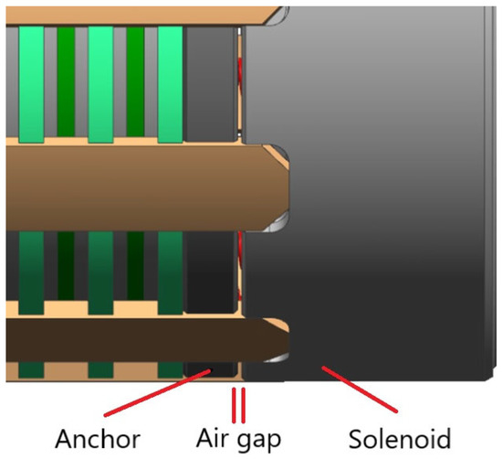 Figure 1. Air gap.
 - -
- Number of springs Ns, which defines the elastic force Fel on the anchor and influences the load applied to the disk pack and, consequently, the braking torque.
- -
- Materials and thickness of the coupled rotor/stator, which determine the tribological behavior of the brake.
- -
- Number of disks Nd, which determines the number of friction surfaces and the braking torque. The correct determination of this parameter allows not only an adequate braking performance but also proper wear resistance.
The studied electromagnetic brake has a base configuration based on the design parameters and materials shown in Table 1.

Table 1.
Design specs of the brake’s base configuration.
The rotor friction material was a carbon material with long interlaced fibers. From a tribological point of view, the described and actual configurations of this kind of brake ensured good braking performance, but the duration was too limited, and the system could not properly work as early as before the Time Before Overhaul (TBO), which represents the number of working cycles before the aircraft component requires an overhaul.
This finding was confirmed during the qualification test in compliance with the standard for the environmental testing of avionics hardware, DO-160 [30].
2.2. Experimental Wear Characterization and Optimization of the Wear Behavior
The objective of this work was the experimental wear characterization of the braking system and a consequent review of the current design configuration to enhance the wear resistance and durability of the aviation component.
The experimental characterization was designed in such a way that, at each step, one single modification was made to the current configuration so that the influence of each design modification on the durability of the component could be studied. This experimental characterization design also contributed to setting a standardized procedure to test this braking system to gather specific information to improve its performance.
The experimental characterization was performed with the following steps, as summarized in Figure 2:
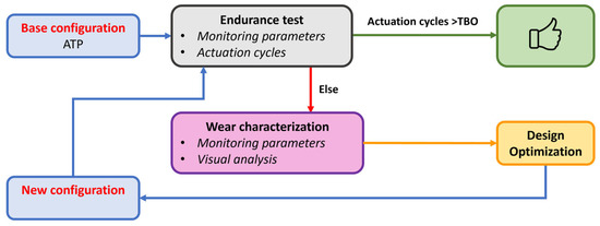
Figure 2.
Experimental characterization and optimization procedure.
- -
- A preliminary Acceptance Test Procedure (ATP) aimed at checking that the brake has no operational flaws and at defining a set of reference working parameters;
- -
- The experimental characterization of the failure causes by monitoring specific working parameters during an endurance test of the base configuration until brake failure;
- -
- The design of modifications to optimize the wear behavior;
- -
- An endurance validation test after the redesign phase to investigate the effective optimization of the wear behavior and durability.
The redesign phase was performed after the first endurance test of the base configuration and was based on the results of this experiment, which gave information about the main criticalities of the system in terms of wear resistance.
2.3. Test Bench and Monitoring Parameters
The brake was tested on a test bench with a slope that was determined considering the range of positions of the brake in a real working environment. A set of monitoring parameters were measured through the test rig, allowing the conditions of the brake to be checked in terms of wear, and the wear progress was correlated with changes in these parameters. Measurements were performed at the beginning, in the middle and at the end of each test.
The monitoring parameters were:
- -
- Engagement threshold voltage Ve, which represents the minimum supply voltage for the solenoid to be able to engage the anchor. Variations in this parameter give an indication of the wear conditions of the surfaces. In particular, when the wear increases, the disk pack volume is reduced and the air gap increases, resulting in an increase in the threshold voltage. The wear progress gradually increases the air gap until the solenoid is no longer able to engage the anchor and the system fails. In the experimental characterization, this parameter was measured by manually supplying the brake and gradually increasing the voltage.
- -
- Release threshold voltage Vr, which represents the minimum supply voltage for the solenoid to keep the anchor engaged. Variations in this voltage also provide information about the wear progress. In fact, if the air gap is wider due to wear, the initial release voltage slowly becomes insufficient to keep the anchor engaged with respect to the elastic force exerted by the springs. When this condition is reached, the solenoid partially or totally releases the anchor, even at voltages compatible with engagement conditions. The measurement of this voltage was performed by gradually reducing the voltage to the solenoid while the anchor was engaged until the anchor was released and checking eventual partial releases.
- -
- Inductance H, which provides information about variations in the air gap and therefore about wear. In fact, if the air gap becomes wider due to wear, the reluctance increases with a consequent inductance decrease. During the middle check, the inductance was measured through an LCR tester to check that the value was between the established minimum and maximum.
- -
- Braking torque Tb, which represents the fundamental performance parameter of the brake and which is strongly influenced by the tribological conditions of the surfaces. This parameter was measured by using a torque wrench and evaluating the maximum torque that can be applied without the occurrence of slips between rotors and stators.
3. Results and Discussion
3.1. Endurance Test Results and Wear Characterization of the Base Configuration
The endurance test of the base configuration was performed on the test bench by monitoring the different working parameters as a percentage of the reference results obtained during the preliminary ATP. The results are represented in Figure 3, Figure 4, Figure 5 and Figure 6.
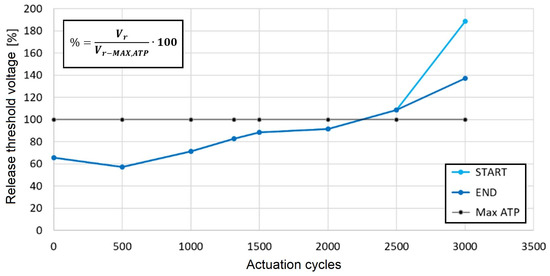
Figure 3.
Release threshold voltage in the base configuration.
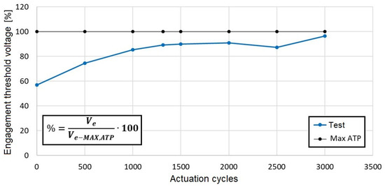
Figure 4.
Engagement threshold voltage in the base configuration.
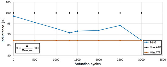
Figure 5.
Inductance in the base configuration.
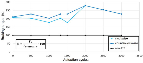
Figure 6.
Braking torque in the base configuration.
Figure 3 reports the trend of the release threshold voltage, which increases up to a value of about 200% of the maximum value obtained during the preliminary ATP. The start curve represents the values of the release threshold voltage when the anchor starts to be released, and the end curve reports the values of the voltage when the anchor’s release stops. The start and end curves should be coincident if the anchor is uniformly released. Given that these two curves are not coincident after 2500 actuation cycles, the anchor’s release is not uniform, and the air gap progressively increased during the test while the anchor was engaged.
The increase in the release threshold voltage suggests that particles of worn material from the disk pack are located between the solenoid and the anchor, and the difference between the start and end curves suggests that the worn material is not uniformly distributed at the interface, but a greater number of wear particles are located in a portion of the interface, which is also justified by the test rig slope.
Figure 4 and Figure 5 show the trend of the engagement threshold voltage and that of the inductance, respectively. These results suggest that the air gap increases due to the wear progress. In fact, the air gap increase implies both that the inductance decreased during the test and that the engagement threshold voltage increased because a greater power supply is necessary for the solenoid to generate a sufficient magnetic field to engage the anchor.
Figure 6 shows the trend of the braking torque, which is higher than the minimum value resulting from the ATP and reaches 300% of the reference maximum value. This result demonstrates that despite the short durability, the braking system maintains a sufficient braking capacity.
It is worth evaluating the changes in the friction coefficient during the test by calculating
where N is the number of contact mating surfaces, F is the normal force on the disks, f is the friction coefficient, and D and d are the maximum and minimum diameters of the contact surface, respectively. The results are reported in Figure 7, where it is shown that the friction coefficient slightly fluctuates around an average value of 0.3.
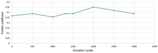
Figure 7.
Friction coefficient in the base configuration.
From the overall analysis of the experimental results obtained on the test rig, one can conclude that the braking system in its base configuration stops working after 3000 actuation cycles, where 1 actuation cycle is considered the sequence of a retraction and an extension. This number of cycles is considerably lower than the minimum number of cycles prescribed for the TBO.
At the end of this endurance test, a visual analysis of the sample braking components was conducted using a digital microscope. When the brake was dismounted from the test rig and opened, a large number of wear particles were evident, and a visual inspection highlighted that the stator disks were more worn than the rotor disks, as can be observed in Figure 8.
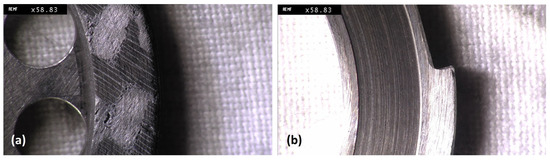
Figure 8.
Worn disks: (a) rotor; (b) stator.
The trend of the release threshold voltage (Figure 3) is strongly related to this evidence. In fact, as the stator disks are made of ferromagnetic materials, they release ferromagnetic particles, which are attracted by the magnetic field generated by the solenoid, and they crowd around the interface between the solenoid and anchor, causing the nonuniform release of the anchor, as also demonstrated by the visual inspection of the solenoid.
3.2. First Optimization of the Wear Behavior: Eight-Spring Configuration
The first optimization of the wear behavior of the brake was based on the results reported in the previous paragraph, which demonstrated that the main criticality of the system in terms of wear resistance is the wear progress on the stators, which causes the interposition of ferromagnetic particles at the solenoid/anchor interface.
The anchor can be released when the elastic force Fel exerted by the springs is greater than the magnetic force Fm exerted by the solenoid. Figure 9 shows the force trend vs. the airgap thickness, where Fm,max represents the force exerted by the solenoid at the maximum supply voltage necessary to engage the anchor, and Fm,min is the magnetic force when the solenoid is supplied with a reduced voltage after the anchor’s engagement.
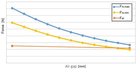
Figure 9.
Forces vs. air gap.
The failure of the brake occurs when the worn material interposed between the anchor and solenoid generates an airgap increase, and the Fm necessary to keep the anchor engaged becomes lower than the elastic force Fel. In this condition, the supply voltage is not sufficient to keep the anchor engaged, and the anchor’s release occurs.
Therefore, despite the fact that the solenoid is supplied with a voltage that is nominally sufficient to keep the anchor engaged, the anchor is released, and the brake is subjected to an irregular closure.
A possible solution to this problem is the reduction in the elastic force, which, however, implies a reduction in the braking torque. Nevertheless, the results reported in Figure 6 suggest that a new configuration with eight springs could allow a braking torque in an acceptable range. Therefore, the first configuration was newly redesigned according to the specifications reported in Table 2.
Table 2.
Design specs of the brake’s first configuration (8-spring configuration).
3.3. Endurance Test of the First Optimized Configuration with Eight Springs
The results of the endurance test performed on the eight-spring configuration are presented in Figure 10, Figure 11, Figure 12 and Figure 13, where they are compared with the results obtained for the base configuration.
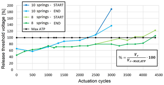
Figure 10.
Release threshold voltage in the 8-spring and 10-spring (base) configurations.
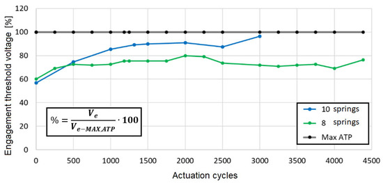
Figure 11.
Engagement threshold voltage in the 8-spring and 10-spring (base) configurations.
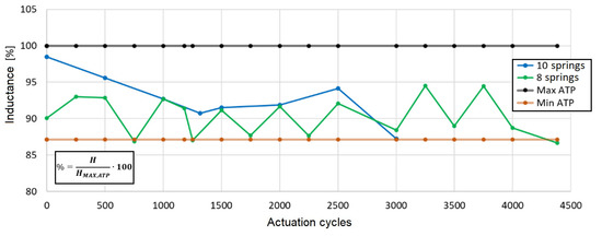
Figure 12.
Inductance in the 8-spring and 10-spring (base) configurations.
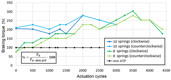
Figure 13.
Braking torque in the 8-spring and 10-spring (base) configurations.
Figure 10 compares the release threshold voltage for the 8-spring and base configurations (10 springs), also showing that, in the 8-spring configuration, the anchor starts undergoing partial and nonuniform engagement after around 2500 actuation cycles. The release threshold voltage trend again suggests that particles of worn material from the disk pack are located between the solenoid and the anchor and that the worn material is not uniformly distributed at the interface.
Figure 11 and Figure 12 compare the engagement threshold voltage and inductance in the eight-spring and base configurations, respectively, suggesting that wear progress also occurs in the eight-spring configuration. Nevertheless, the engagement threshold voltage always remains less than the reference maximum ATP value.
Figure 13 reports the braking torque comparison for the eight-spring and base configurations. The results show that in the eight-spring configuration, the initial braking torque is less than the minimum value established with the ATP, but it rapidly reaches acceptable values, although less than in the base configuration, as was expected.
Figure 14 shows the trend of the friction coefficient during the test, which varies from a relatively low value of around 0.1 to a high value close to 0.5.
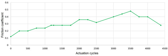
Figure 14.
Friction coefficient in the 8-spring configuration.
The overall analysis of the results for the eight-spring configuration demonstrates that, although this configuration has a better wear resistance than the base configuration, as it reaches the failure point after around 4500 actuation cycles, this improvement is not sufficient, as the failure occurs before the TBO.
Again, in this case, the visual analysis of the sample braking components at the end of the endurance test demonstrated the presence of a large number of ferromagnetic particles, as can be observed in Figure 15.
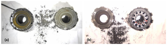
Figure 15.
Eight-spring configuration after test: (a) solenoid and anchor; (b) stator and rotor.
Therefore, the failure of the braking system is due to the accumulation of ferromagnetic particles between the anchor and solenoid, mainly originating from wear progress on the stator disks. These results lead to the conclusion that possible further optimization in terms of the wear resistance and durability of the system lies in a reduction in the ferromagnetic wear material and thus in a change in the friction pair materials.
The carbon fiber used as friction material for the rotor disks could be identified as possibly responsible for the severe wear phenomenon on the stainless-steel stator. This could be due to different factors, such as the low operating temperature of the brake and the different wear behaviors of the matrix and reinforcement of carbon fiber. For this reason, a different friction material was analyzed.
3.4. Final Optimization of the Wear Behavior: NAO Configuration
The new friction material used for the rotor disks was a non-asbestos organic (NAO) friction composite, which is a polymer-reinforced material (Figure 16).
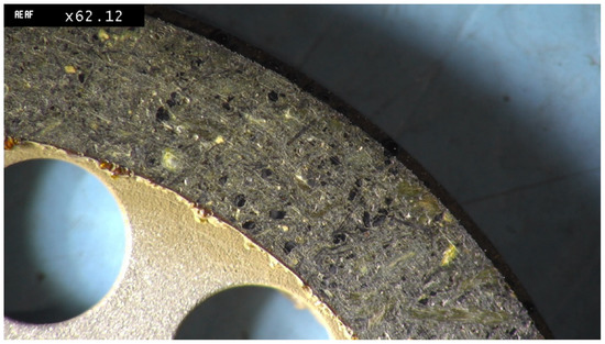
Figure 16.
Rotor disk with NAO as friction material.
This material is mainly composed of a phenolic resin combined with nitrile butadiene rubber (NBR), short-fiber reinforcement, fillers, and metallic particles, with 15–40% ferrous materials. From a mechanical point of view, this material is rigid with high hardness and mechanical resistance.
The new configuration to be analyzed was set according to the specifications reported in Table 3.
Table 3.
Design specs of the brake’s NAO configuration.
3.5. Endurance Test of the Final Optimized Configuration
The results of the endurance test performed on the brake in the NAO configuration are represented in Figure 17, Figure 18, Figure 19 and Figure 20, where a comparison with the results obtained in the base configuration is shown.
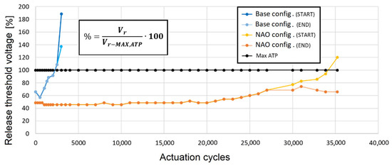
Figure 17.
Release threshold voltage in the base and NAO configurations.
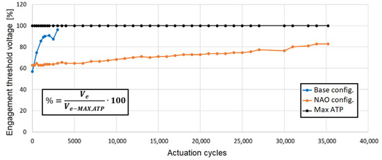
Figure 18.
Engagement threshold voltage in the base and NAO configurations.
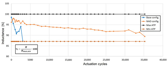
Figure 19.
Inductance in the base and NAO configurations.
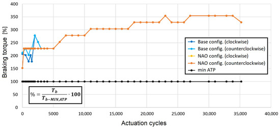
Figure 20.
Braking torque in the base and NAO configurations.
Figure 17 shows the release threshold voltage of the anchor in the NAO configuration compared with the same voltage measured in the base configuration. The trend is stationary for up to 20,000 actuation cycles, and it shows an increasing trend afterward, suggesting that the air gap starts to widen, probably due to the presence of wear particles.
After 27,000 actuation cycles, the anchor is released nonuniformly, which suggests that the wear particles are mainly crowded in a portion of the interface, probably the lower portion due to the slope. The failure of the brake occurs at 35,000 actuation cycles.
In Figure 18, the engagement threshold voltage of the NAO configuration is shown in comparison with the same voltage measured in the base configuration. In this case, one can observe that the engagement voltage increases with the number of actuation cycles, which suggests some wear progress, but it remains lower than the ATP value.
These results are also confirmed by the monitored inductance (Figure 19) compared with the inductance measured in the base configuration, which presents a decreasing trend compatible with an increase in the air gap due to wear.
The trend of the braking torque in the NAO configuration (Figure 20) shows higher values than the minimum value to guarantee an efficient braking effect.
Its increasing trend with respect to the actuation cycles depends on the stabilization of the tribological system, which implies an increase in the effective contact area at the interface and an increase in friction. The tribological stabilization of the system allows a friction coefficient of 0.45 to be reached, as reported in Figure 21.
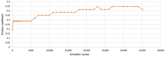
Figure 21.
Friction coefficient in the NAO configuration.
The implementation of the NAO configuration allowed the achievement of 35,000 actuation cycles, with an increase in the brake operation duration of about ten times compared to the base configuration.
Although the brake showed improved and sufficient durability that satisfied the TBO, the visual analysis of the braking components at the end of the endurance test demonstrated the occurrence of wear.
Figure 22 shows the superficial condition of the NAO friction material. The presence of cavities and scratches is due to the removal of reinforcement splinters, which causes the wear and weakening of the surfaces. The number of ferromagnetic wear particles at the interface is still lower than in previous configurations. In this case, in contrast to the previous configurations, the rotors are the main worn components; therefore, the ferromagnetic wear particles derive from the NAO friction material, which is a more desirable condition.
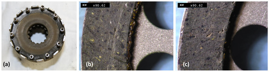
Figure 22.
Worn components: (a) solenoid; (b) rotor 1; (c) rotor 2.
3.6. Comparison of Results and Discussion
The results of this work are reported in Table 4, where the three analyzed configurations are compared in terms of wear, durability, and maximum braking torque normalized with respect to the minimum ATP value.
Table 4.
Comparison of results.
The NAO configuration shows the best results in terms of durability, wear, and braking torque compared to both the base and eight-spring configurations. This improvement over configurations with carbon fiber as the friction material is due to the low operating temperature of the brake and the wear behavior of the different material structures and reinforcements. Although the heterogeneity of the NAO due to the polymeric structure with reinforcements results in good mechanical properties, the wear behavior is nonuniform.
Figures reporting the results of the monitoring parameters during the endurance tests performed on the NAO and base configurations demonstrate that the trends of these parameters are similar, although the failure of the NAO configuration occurs after about 35,000 actuation cycles. Furthermore, although the NAO configuration results in an optimized braking system, the failure of the brake is still associated with wear progress and the presence of ferromagnetic particles at the interface.
This evidence suggests that, even in the optimized NAO configuration, the presence of ferromagnetic wear particles remains related to the failure of the electromagnetic brake, as these particles contribute to the increase in the air gap. Given that the particles are located between the solenoid and the anchor due to the solenoid attraction, the system is presumed to fail due to the incapacity of the solenoid to generate a sufficient magnetic field to guarantee the total aperture of the brake.
The results of this study are related to a specific industrial braking system for helicopters and are aimed at improving the durability and efficiency of the device, optimizing its tribological behavior and wear resistance. The literature contains few similar studies on electromagnetic brakes for the same application, as the performance of a braking system is strongly dependent on its structure, the chosen materials, the actuation, and other thermal issues. A few works can be taken into consideration for a comparison, mainly in terms of procedures. For instance, the studies in [24,25] are both focused on the design optimization of brakes for aircraft and helicopters based on the analysis of the tribological behavior, but different architectures, actuation technologies, and materials are considered compared to the work presented here. In [24], the brake is based on a disk and clasping arm arrangement, and the actuation is hydraulic. Different friction materials were experimentally tested—a semi-metallic material and some non-asbestos organic materials—with the aim of meeting a set of established requirements in terms of the holding torque, mass, volumetric constraints, and fast engagement. For these purposes, an NAO material was chosen as the best one (Trimat MR2215). This finding matches the results of this study, which demonstrated the best performance with the NAO configuration. In [25], new asbestos-free friction linings were analyzed considering four materials by calculating the distribution of the contact pressures with numerical models and comparing results with experimental ones. Again, in this case, different materials and configurations were investigated. In [29], an electromagnetic brake for aeronautical applications with a similar structure to that of the brake presented in this paper was prototyped and analyzed, but the authors considered several design issues not specifically concerning tribological aspects.
4. Conclusions
This paper was aimed at the wear characterization and tribological optimization of a power-off electromagnetic brake for helicopters. A base configuration based on the tribological pair stainless steel/carbon fiber was tested, and an optimized friction pair configuration was proposed using an NAO as the friction material instead of carbon (NAO configuration). Another optimized configuration was proposed based on a reduction in the number of springs (eight-spring configuration).
Both optimized configurations were aimed at reducing wear phenomena and showed an improvement in the durability of the braking system in terms of the number of actuation cycles before failure. The eight-spring configuration did not exhibit sufficient durability with respect to the TBO, while the NAO configuration showed a durability of about 35,000 cycles.
Although the NAO configuration gave optimal results and was efficient and reliable in terms of durability, this paper demonstrates that the wear progress and the presence of ferromagnetic particles inside the reinforcement of the NAO material were still related to a system failure, as in the initial base and eight-spring configurations. Therefore, further improvements in the braking system can be envisaged by analyzing different friction pairs and primarily reducing the ferromagnetic components between mating surfaces.
Author Contributions
Conceptualization, S.L. and M.C.V.; methodology, S.L. and M.C.V.; validation, S.L. and M.C.V.; formal analysis, S.L. and M.C.V.; investigation, S.L. and M.C.V.; resources, S.L. and M.C.V.; data curation, S.L. and M.C.V.; writing—original draft preparation, S.L. and M.C.V.; writing—review and editing, S.L. and M.C.V.; visualization, S.L. and M.C.V.; supervision, S.L. and M.C.V.; project administration, S.L. and M.C.V. All authors have read and agreed to the published version of the manuscript.
Funding
This research received no external funding.
Institutional Review Board Statement
Not applicable.
Data Availability Statement
Restrictions apply to the availability of these data. Data were obtained from UMBRAGROUP S.p.A. and are available from the authors with the permission of UMBRAGROUP S.p.A.
Acknowledgments
The authors warmly acknowledge UMBRAGROUP S.p.A. and Eng. N. Matteuzzi for their technical support and Eng. Lorenzo Troiani.
Conflicts of Interest
The authors declare no conflict of interest.
References
- Iqbal, H.; Yi, B.J. Design of a new bilayer multipole electromagnetic brake system for a haptic interface. Appl. Sci. 2019, 9, 5394. [Google Scholar] [CrossRef]
- Logozzo, S.; Valigi, M.C.; Malvezzi, M. Characterization of a snap gear for the arrester system of military aircrafts. Int. J. Mech. Control. 2022, 23, 61–67. [Google Scholar]
- Hameed, A.; Zubair, O.; Taimur, A.S.; Mehmood, Z.; Javed, A.; Mehmood, Z. Failure analysis of a broken support strut of an aircraft landing gear. Eng. Fail. Anal. 2020, 117, 104847. [Google Scholar] [CrossRef]
- Yang, X.; Yang, J.; Zhang, Z.; Ma, J.; Sun, Y.; Liu, H. A review of civil aircraft arresting system for runway overruns. Prog. Aerosp. Sci. 2018, 102, 99–121. [Google Scholar] [CrossRef]
- Cianetti, F.; Ciotti, M.; Palmieri, M.; Zucca, G. On the evaluation of surface fatigue strength of a stainless-steel aeronautical component. Metals 2019, 9, 455. [Google Scholar] [CrossRef]
- Valigi, M.C.; Logozzo, S.; Alvino, A.; De Angelis, F. Dynamic characterization of wire rope isolators for transportation of aerospace electronic systems. Int. J. Mech. Control. 2021, 22, 105–114. [Google Scholar]
- Valigi, M.C.; Braccesi, C.; Logozzo, S. A Parametric Study On Friction Instabilities In Mechanical Face Seals. Tribol. Trans. 2016, 59, 911–922. [Google Scholar] [CrossRef]
- Fan, S.; Yang, C.; He, L.; Du, Y.; Krenkel, W.; Greil, P.; Travitzky, N. Progress of ceramic matrix composites brake materials for aircraft application. Rev. Adv. Mater. Sci. 2016, 44, 313–325. [Google Scholar]
- Peng, J.; Tang, X.; Chen, B.; Jiang, F.; Yang, Y.; Zhang, R.; Gao, D.; Zhang, X.; Huang, Z. Failure type prediction using physical indices and data features for solenoid valve. Appl. Sci. 2020, 10, 1323. [Google Scholar] [CrossRef]
- Yasa, Y.; Sincar, E.; Ertugrul, B.T.; Mese, E. Design Considerations of Electromagnetic Brakes for Servo Applications. In Proceedings of the IEEE International Symposium on Industrial Electronics, Istanbul, Turkey, 1–4 June 2014; pp. 768–774. [Google Scholar] [CrossRef]
- Park, S.; Lee, K.; Kim, S.; Kim, J. Brake-Disc Holes and Slit Shape Design to Improve Heat Dissipation Performance and Structural Stability. Appl. Sci. 2022, 12, 1171. [Google Scholar] [CrossRef]
- Shemanske, R. Electronic Motor Braking. IEEE Trans. Ind. Appl. 1983, IA-19, 824–831. [Google Scholar] [CrossRef]
- Kwon, S.J.; Kim, C.J. Contribution Analysis of Assembled Brake System to Reduce Squealing. Appl. Sci. 2022, 12, 11232. [Google Scholar] [CrossRef]
- Úradníček, J.; Musil, M.; Gašparovič, L.; Bachratý, M. Influence of material-dependent damping on brake squeal in a specific disc brake system. Appl. Sci. 2021, 11, 2625. [Google Scholar] [CrossRef]
- Chu, Z.; Zheng, F.; Liang, L.; Yan, H.; Kang, R. Parameter determination of a minimal model for brake squeal. Appl. Sci. 2018, 8, 37. [Google Scholar] [CrossRef]
- Goo, B.C. A study on the contact pressure and thermo-elastic behavior of a brake disc-pad by infrared images and finite element analysis. Appl. Sci. 2018, 8, 1639. [Google Scholar] [CrossRef]
- Kim, S.; Hong, S.; Kim, J.; Yoo, H. Performance assessment of a developed brake frame based on the application of a proposed equivalent model in a net protection system for debris flow. Appl. Sci. 2018, 8, 1101. [Google Scholar] [CrossRef]
- Ricciardi, V.; Augsburg, K.; Gramstat, S.; Schreiber, V.; Ivanov, V. Survey on modelling and techniques for friction estimation in automotive brakes. Appl. Sci. 2017, 7, 873. [Google Scholar] [CrossRef]
- Kumar, N.; Bharti, A.; Goyal, H.S.; Patel, K.K. The evolution of brake friction materials: A review. Mater. Phys. Mech. 2021, 47, 796–815. [Google Scholar] [CrossRef]
- Veeman, D.; Katiyar, J.K.; Ruggiero, A. Tribo-mechanical performance of brake composite material: A comprehensive review. Tribol.—Mater. Surf. Interfaces 2023, 1–24. [Google Scholar] [CrossRef]
- Darius, G.S.; Berhan, M.N.; David, N.V.; Shahrul, A.A.; Zaki, M.B. Characterization of brake pad friction materials. WIT Trans. Eng. Sci. 2005, 51, 43–50. [Google Scholar]
- Sun, D.; Hu, F.; Qin, D.; Liu, Z. An experimental analysis on thermal stress distributions in a multiple disc wet brake. Zhongguo Jixie Gongcheng/China Mech. Eng. 2010, 21, 2006–2010. [Google Scholar]
- Liang, H.; Shan, C.; Wang, X.; Hu, J. Matching Analysis of Carbon-Ceramic Brake Discs for High-Speed Trains. Appl. Sci. 2023, 13, 4532. [Google Scholar] [CrossRef]
- Booker, J.D.; Lock, R.J.; Drury, D. Design and physical prototyping of a novel braking system for a helicopter rotor. Designs 2019, 3, 40. [Google Scholar] [CrossRef]
- Lacki, P. Friction conditions in the friction brake system of Mi-2 helicopter. Arch. Civ. Mech. Eng. 2013, 13, 297–303. [Google Scholar] [CrossRef]
- Zhao, Y.; Lin, H.; Elahi, H.; Miao, F.; Riaz, S. Clamping Force Sensor Fault Analysis and Fault-Tolerant Control of the Electromechanical Brake System. Arab. J. Sci. Eng. 2023, 48, 6011–6023. [Google Scholar] [CrossRef]
- Valigi, M.C.; Logozzo, S.; Butini, E.; Meli, E.; Marini, L.; Rindi, A. Experimental evaluation of tramway track wear by means of 3D metrological optical scanners. In Proceedings of the 11th International Conference on Contact Mechanics and Wear of Rail/Wheel Systems (CM2018), Delft, The Netherlands, 24–27 September 2018; pp. 1007–1012. [Google Scholar]
- Affatato, S.; Valigi, M.C.; Logozzo, S. Knee wear assessment: 3D scanners used as a consolidated procedure. Materials 2020, 13, 2349. [Google Scholar] [CrossRef] [PubMed]
- D’Andrea, M.; Di Domenico, G.; Macera, D.; Fiume, F. Electromagnetic brakes in electromechanical actuators for aerospace applications. In Proceedings of the 2020 International Symposium on Power Electronics, Electrical Drives, Automation and Motion, SPEEDAM, Sorrento, Italy, 24–26 June 2020; pp. 484–488. [Google Scholar] [CrossRef]
- DO-160; Environmental Conditions and Test Procedures for Airborne Equipment. RTCA: Washington, DC, USA, 1975.


Disclaimer/Publisher’s Note: The statements, opinions and data contained in all publications are solely those of the individual author(s) and contributor(s) and not of MDPI and/or the editor(s). MDPI and/or the editor(s) disclaim responsibility for any injury to people or property resulting from any ideas, methods, instructions or products referred to in the content. |
© 2023 by the authors. Licensee MDPI, Basel, Switzerland. This article is an open access article distributed under the terms and conditions of the Creative Commons Attribution (CC BY) license (https://creativecommons.org/licenses/by/4.0/).