Article

Mechanical Performance Analysis and Experimental Study of Four-Star-Type Crank-Linkage Mechanism

College of Naval Architecture and Ocean, Naval University of Engineering, Wuhan 430033, China
*
Author to whom correspondence should be addressed.
Appl. Sci. 2023, 13(14), 8202; https://doi.org/10.3390/app13148202
Submission received: 10 June 2023 / Revised: 29 June 2023 / Accepted: 12 July 2023 / Published: 14 July 2023
(This article belongs to the Section Acoustics and Vibrations)

Abstract

:
Mechanical performance analysis and experimental study of the mechanics of the four-star-type crank-linkage mechanism of the marine air compressor were carried out to improve the submerged floating performance and stealth performance of the underwater vehicle and to meet the demand of its large diving depth. Firstly, we analyzed the forces on the four-star-type crank-linkage mechanism, derived the inertia forces and moments of the crank-linkage mechanism, and proved the advantages of the four-star-type crank-linkage mechanism in balancing the second-order reciprocating inertia forces. The static strength of some parts was calibrated, and the modal analysis of the four-star-type crank-linkage mechanism was carried out. Second, a flexible crankshaft dynamics model was established to study the influence of kinematic pair parameters on the excitation characteristics of the main bearing. The mechanical performance analysis of the mechanics of the four-star-type crank-linkage with clearance was carried out. Finally, a test bench of four-star-type crank-linkage mechanism was designed and built independently to analyze the effects of clearance size and rotational speed on the acceleration of the motion and vibration acceleration of the slider. The results show that the first-order reciprocating inertia force and second-order reciprocating moment of inertia mainly exist in the four-star-type crank-linkage mechanism. The friction force of the revolving pair can suppress part of the resonance peak, but it will broaden the excitation band and excite high-frequency vibration. The larger the clearance of the four-star-type crank-linkage mechanism kinematic pair, the higher the crankshaft speed, the larger the acceleration amplitude, and the more concentrated the phase trajectory. The research results of this paper can guide the low-noise design of other types of air compressors, help to improve the overall level of marine air compressors, and show future directions for the vibration control of four-star-type air compressors.

1. Introduction

The marine air compressor mainly provides compressed air for starting diesel engines, pneumatic machinery manipulation, weapon firing, and underwater vehicle diving and floating. It is an indispensable piece of equipment for a pneumatic system. The main focuses of recent air compressor research have primarily been on fault detection and diagnosis, strength verification of the structure, and thermodynamic analysis. However, there has been relatively little research on the vibration control of large air compressors, particularly a systematic study on the vibration characteristics of four-star air compressors, which remain largely unexplored [1]. Four-star air compressors, with their compact layout, high exhaust pressure, excellent self-balancing properties, and relatively low vibration, have become the preferred system for submarines in military superpowers. Yet, the vibration of compressors is caused by numerous factors including imbalance forces and torques, friction excitation, valve shocks, airflow pulsation, and motor vibration. A thorough analysis of these vibration sources will substantially increase the workload for the overall vibration research on the machine. The main moving part of the air compressor is the crank-linkage mechanism. Only considering the crank-linkage excitation force to predict the vibration response of the whole machine has become the mainstream of air compressor vibration analysis [2]. The different lubrication and wear states of the crank-linkage mechanism kinematic pair will cause changes in mechanical characteristics. The crank-linkage dynamic balance condition also has a large impact on the mechanical characteristics.
During the operation of the crank-linkage mechanism, the kinematic pair is inevitably subjected to a certain clearance due to lubrication needs and later wear, which has a certain impact on the piston motion state [3]. When the clearance value exceeds the permissible limit, it will not only consume the system energy sharply but also produce large amounts of vibration. In severe cases, this can lead to system instability and even accidents [4]. A one-dimensional shock model of the crank-linkage mechanism was proposed by Doubowsky et al. [5]. Subsequently, many researchers and scholars have explored the modeling of kinematics pairs with clearance. In recent years, the modeling of kinematic pairs with clearance has been continuously developed and improved. Three types of representative clearance kinematics pairs have been developed, namely the continuous contact model, “contact-separation” two-state model, and “contact-separation-collision” three-state model. After clarifying the motion states of the kinematic pair with clearance, the specific analysis needs to be implemented into the mechanical analysis of the contact surface. There are two main methods for modeling and analyzing the contact-collision problem: the discrete analysis method and continuous analysis method [6]. The discrete analysis method, also known as the non-smooth rigid-body analysis method, assumes that impacts occur instantaneously, primarily using linear complementarity and differential variation inequalities. The former prevents mutual penetration of the kinematic pair elements, while the latter uses plain integrators for direct calculation [7]. The continuous analysis method refines the collision process, expressing it as a continuous function of collision force and deformation. The emphasis of studying the dynamic characteristics of motion pairs with a gap lies in establishing relatively accurate contact-collision force models. Current research levels can consider non-linearity, friction, and energy losses during the contact-collision process. As mechanical manufacturing evolves, kinematic pair mechanisms are leaning towards high-speed and heavy-load directions, increasingly amplifying the effects of gap motion pairs [8]. Different dynamics may be encountered for different research targets, and theoretical models can predict the system’s dynamic behavior through simulations and experimental studies.
Control of mechanical vibration in reciprocating air compressors is a complex process. Factors such as the unbalance of inertia force and torque in the crank-connecting rod, overturning torques due to gas forces, vibrations caused by motor operation, and vibrations due to cyclic intake and exhaust from the compressor all contribute to the overall vibration noise level of the air compressor [9]. When conducting multibody dynamics analysis on the four-star crank-connecting rod mechanism, the existence of a gap is usually ignored and ideally processed. However, in actual engineering, gaps formed due to part manufacturing, assembly of the motion pair, and wear and tear during operation are inevitable [10]. The collision forces caused by the motion pair gap not only consume the mechanical system’s energy but also induce vibration, noise, and dynamic output in the system. In high-speed, heavy-load machinery, gaps can lead to violent contacts and collisions between elements of the motion pair, with reaction forces rising to several times their normal values, inducing greater deformation, wear, and increased vibration noise and seriously affecting the efficiency and lifespan of the machine [11]. The key to analyzing the dynamics of a mechanism with a gap motion pair is to establish a relatively accurate gap motion pair model and integrate it into the system dynamics model to obtain a dynamic model that includes the gap.
What are the dynamic characteristics of a four-star-type crank-linkage mechanism? What is the difference in the force of flexible and rigid crank linkage on the main bearing? How can we model the dynamics of a revolving pair with clearance? What are the characteristics of the dynamic characteristics of the crank linkage with clearance? To address these questions, the mechanical characteristics of the four-star-type crank linkage are analyzed and experimentally studied in this paper. Firstly, we simulate the motion of piston and linkage at all levels of air compressor, derive the inertia force and moment of inertia of the four-star-type crank linkage, calibrate the static strength of some parts, and perform modal analysis on the split structure of the crank linkage. Then, we establish the crank-linkage rigid–flexible dynamics model to simulate the force on the main bearing under the action of ideal gas force for the rigid–flexible coupling crank linkage and the kinematic pair of crank linkage with friction. Moreover, the analysis of the characteristics of the four-star-type crank linkage with clearance is carried out. Finally, we design and build a four-star-type crank-linkage test bench independently to analyze the effects of wear clearance and rotational speed on the acceleration response of the slider and the bench.

2. Numerical Calculation of Crank Linkage

2.1. Kinematic Relation of Crank Linkage

The rotating crankshaft compresses the gas by driving the piston in a reciprocating motion through the linkage. The kinematic relationship of the single-row crank linkage is shown in Figure 1. The expressions of piston displacement x, velocity v, and acceleration a are obtained from the geometric position relationship of the crank linkage as follows:
x = r 1 cos θ + 1 λ 1 1 λ 2 sin 2 θ ,   v = ω r sin θ + λ sin 2 θ λ 1 λ 2 sin 2 θ , a = ω 2 r cos θ + λ cos 2 θ 1 λ 2 sin 2 θ + λ 3 sin 2 2 θ 4 1 λ 2 sin 2 θ 3 / 2
where r indicates the crank length, λ = r / l indicates the crank linkage length ratio, ω indicates the crankshaft speed, and θ indicates the crank rotation angle.
Expanding Equation (1) by Taylor formula and removing higher-order terms above the third order, we obtain the following:
x = r 1 cos θ + λ 1 cos 2 θ 4 ,   v = ω r sin θ + λ sin 2 θ 2 ,   a = ω 2 r cos θ + λ cos 2 θ
From Equation (2), only second-order steps exist, and thus, the calculated inertial forces can only go to the second order. If higher-order inertia forces are to be calculated numerically, more higher-order terms should be retained. The linkage combines the rotational motion of the crank and the reciprocating motion of the piston and oscillates reciprocally in the plane, and the angular displacement β , velocity ω c , and acceleration ε c of the barycenter can be expressed as follows:
β = arcsin λ sin θ ,   ω c = λ ω cos θ 1 λ 2 sin 2 θ ,   ε c = λ 1 λ 2 ω 2 sin θ 1 λ 2 sin 2 θ 3 / 2
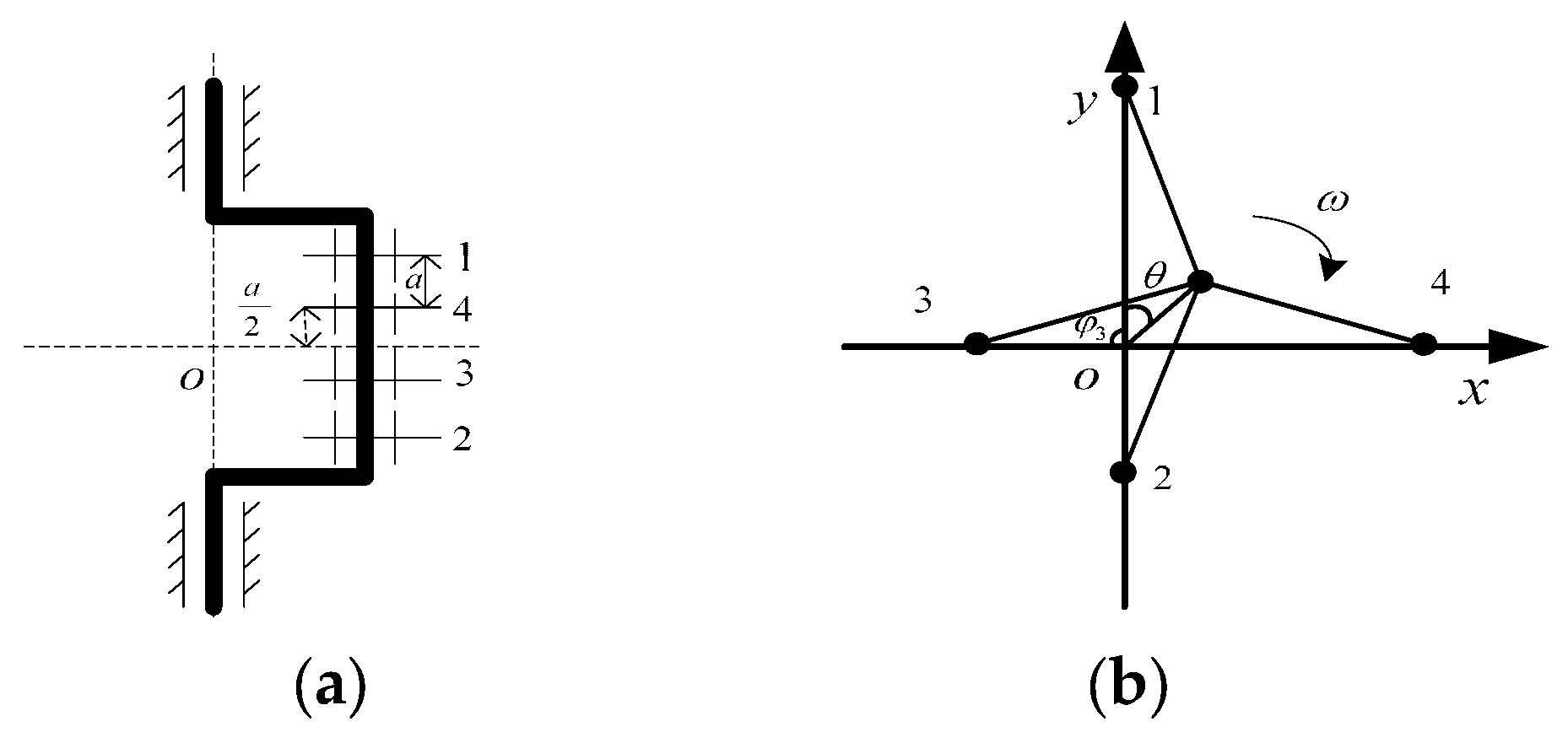
The rectangular coordinate schematic diagram of the crank-linkage mechanism is shown in Figure 2. In the diagram, φ indicates the angle between the center line of any column of the cylinder and the y-axis. The right side of the y-axis is specified as positive, and the left side of the y-axis is negative. θ indicates the angle of crank relative to the y-axis, ω indicates the angular speed of crank rotation, and a indicates the axial distance between the barycenter of two adjacent rows of linkage.
Based on the kinematic relationship of the crank linkage, r = 35 mm, λ = 25/280, and ω = 1480 r/min are substituted into Equations (2) and (3). The phases of one, two, three, and four cylinders differ by 180°, 270°, and 90°, respectively, and the piston acceleration curve and linkage angular acceleration curve are obtained as shown in Figure 3. The acceleration change trend of the opposed two piston columns is the same, and there is some difference in the values. The acceleration curve of a single piston is different from a simple sinusoidal law curve. The acceleration maxima in positive and negative directions are not equal. In one rotation period of the crankshaft, there are two moments when the acceleration of all four pistons is equal and four moments when the acceleration of the opposed two pistons is equal. Moreover, the angular acceleration of the linkage is symmetrical about the equilibrium position, and the acceleration phase is consistent with the geometric phase relationship of each column of the cylinder.

2.2. Force Analysis of Crank Linkage

The main forces acting on the crank linkage are reciprocating inertia force, rotating inertia force, gas force, friction force, piston side-thrust force, and main bearing support reaction force. Inertia force has no force object, which is related to the mass and motion state of the moving parts. Side-thrust force is provided by the cylinder liner, mainly related to the length of the crank linkage [12]. For the established structure of the four-star-type crank-linkage mechanism, the gas force, friction force, and main bearing support reaction force are mainly related to the mechanism motion state and the contact characteristics of the kinematic pair.

2.2.1. Reciprocating Inertia Forces and Moments

The reciprocating inertia force on the crank-linkage mechanism is the combined force of the reciprocating inertia forces generated by the four piston groups and the linkage group [13]. The inertia force is decomposed in the plane in the x-direction and y-direction. The formula for calculating the reciprocating inertia force and moment for a multi-column reciprocating air compressor is shown in Table 1, where F s i m n is the m-order reciprocating inertia force in the n direction for any column i. m s i indicates the mass of reciprocating motion in any column i. M s i m n denotes the m-order reciprocating moment of inertia in the direction of n for any column i. b i denotes the distance of the inertia force to the center of symmetry.
In the process of crank-linkage design, different cylinder bore requirements are met by choosing different materials while keeping the crank and linkage masses equal. Therefore, there is m s 1 = m s 2 = m s 3 = m s 4 = m s , and the combined force of the first-order reciprocating inertia forces in each column on the x-x and y-y axes can be expressed as follows:
F s 1 1 x = m s r ω 2 cos θ sin 0 F s 2 1 x = m s r ω 2 cos θ π sin π F s 3 1 x = m s r ω 2 cos θ + π 2 sin π 2 F s 4 1 x = m s r ω 2 cos θ π 2 sin π 2
F s 1 x = i = 1 4 F s i 1 x = 2 m s r ω 2 cos θ
Similarly, according to the calculation formula in Table 2, we can obtain the following:
F s 1 y = i = 1 4 F s i 1 y = 2 m s r ω 2 sin θ ,   F s 1 = F s 1 x 2 + F s 1 y 2 = 2 m s r ω 2 , M s 1 = M s 1 x 2 + M s 1 y 2 = 0 ,   F s 2 = F s 2 x 2 + F s 2 y 2 = 0 , M s 2 = M s 2 x 2 + M s 2 y 2 = 10 b λ m s r ω 2 cos 2 θ
The above analysis shows that the first-order reciprocating inertia force of the four-star-type crank-linkage is constant, while the first-order reciprocating moment of inertia and the second-order reciprocating inertia force are 0. The second-order reciprocating moment of inertia varies with the change of crank angle. The second-order moment of inertia is smaller due to the smaller crank column width wc and crank linkage ratio λ . While there are higher-order reciprocating inertia forces and moments, in general, only the first- and second-order inertia forces and moments of inertia are considered.

2.2.2. Rotational Inertia Forces and Moments

Rotational inertia forces are relatively simple to calculate compared to reciprocating inertia forces. There is no higher-order rotational moment of inertia due to the deterministic angular acceleration [14]. The rotational inertia force resulting from the motion of the rotating mass m r is
F r = m r a r = m r r ω 2
As the linkage combines reciprocating and rotating motions, the reciprocating and rotating masses are as follows:
m s = m p + 0.3 ~ 0.4 m d ,   m r = b 1 r m z + 0.6 ~ 0.7 m d
where m p represents the piston mass, m d represents the linkage mass, and m z represents the crankshaft mass.
The rotational reciprocating inertia force is given below:
F r = m z b 1 ω 2 + 0.6 ~ 0.7 m d b 2 ω 2
where b 1 represents the distance from the barycenter of crankshaft to the centerline of rotation, and b 2 represents the distance from the barycenter of linkage to the centerline of crankshaft rotation.

2.2.3. Gas Force

An operating cycle of an air compressor consists of compression, exhaust, expansion, and suction. P 1 , P 2 , P 3 , and P 4 denote the gas forces corresponding to each stage, respectively, with the following:
P 1 = S + S c S x + S c k P s A , P 2 = P s A , P 3 = S c S x + S c m P d A , P 4 = P d A , λ P = P s P s = P d P d
where S c is the clearance volume; P s , P d are the suction and exhaust nominal pressure; P s , P d are the actual suction and exhaust pressure after considering the pressure loss; λ P is the pressure coefficient; A is the cylinder cross-sectional area.
The crank angles of compression, exhaust, expansion, and suction are 0~97°, 97~180°, 180~295°, and 295~360°, respectively. Check the relevant standards [15] and take P s = 0.1 MPa, κ = 0.4 , m = 1.4 , and λ P = 0.95 . Based on the gas pressure and the area of the piston of one cylinder, the variation curve of the gas force on the piston with the crank angle under ideal conditions is calculated as shown in Figure 4. The piston starts to compress the gas at 0°. Compressed to a certain extent, the exhaust valve opens under the action of differential pressure. Currently, the gas force on the piston remains unchanged, and the piston continues to move toward the cylinder head. When the piston approaches the apex, the exhaust valve closes under the action of differential pressure, the piston moves down, and the gas force drops sharply. As there is high-pressure gas in the remaining clearance volume, the inlet valve opens slightly later. After the inlet valve is opened, the air compressor starts to feed gas, and the gas force on the piston remains unchanged until it enters the next cycle of the compression process.

2.2.4. Friction and Multiple Piston Forces

The shaft-side gas is the atmospheric pressure. The frictional force F f is always in the opposite direction of the movement of piston, and the indicated power is expressed in N i d ; then, we obtain the following:
λ v = 1 S c ε s ε d ε 1 m 1
where ε s is the compressibility coefficient of the gas in the nominal suction condition, ε d is the compressibility coefficient of the gas in the nominal exhaust condition, m is the polytropic coefficient, ε is the pressure ratio, and λ v is the volume coefficient.
N i d = 1.634 P s V t λ v κ κ 1 P d P s κ κ 1 1 + ε s + ε d 2 ε s
where V t is the stroke volume of the piston, and κ is the adiabatic coefficient.
F f = 0.6 N i d 1 η m 1 60 × 102 4 ω r
where η m is the mechanical efficiency. Referring to the relevant data [15], η m = 0.78 and ε s = ε d are taken.
The reciprocating inertia force along the centerline of the cylinder F l s , the gas force F g , and the friction force F f are collectively referred to as the multiple piston force, F p , which is the following:
F p = F l s + F g + F f
The side thrust of the piston F h can be expressed as given below:
F h = F p λ sin θ 1 λ 2 sin 2 θ
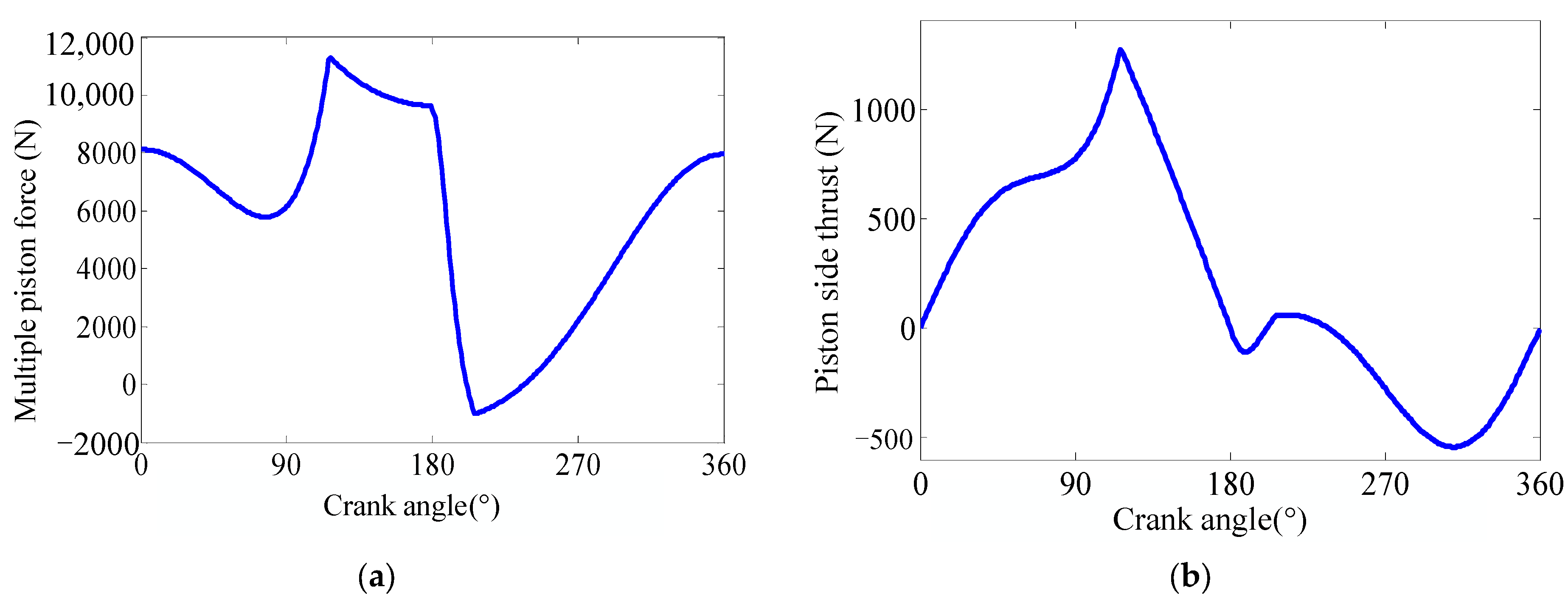
The variation in the multiple piston force and piston side thrust with crank angle is shown in Figure 5. As reciprocating inertia force and friction force are considered, the piston force fluctuates in both suction and exhaust phases. When the exhaust valve is open, the multiple piston force and the piston side thrust achieve the maximum value at the same time. When the intake valve is opened, the multiple piston force achieves the reverse maximum, while the reverse maximum of the piston side thrust is delayed.

2.3. Static Strength Verification of Some Parts

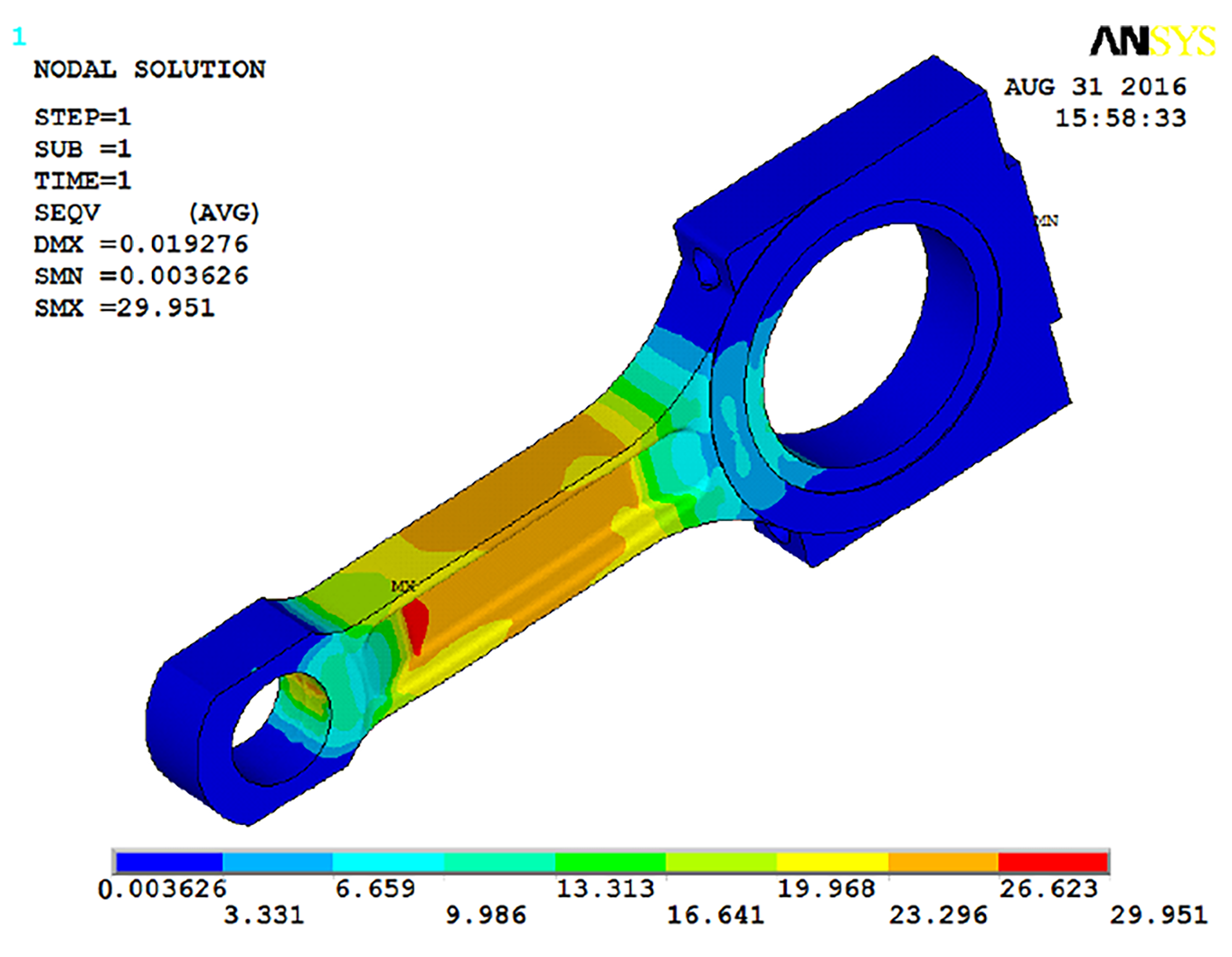
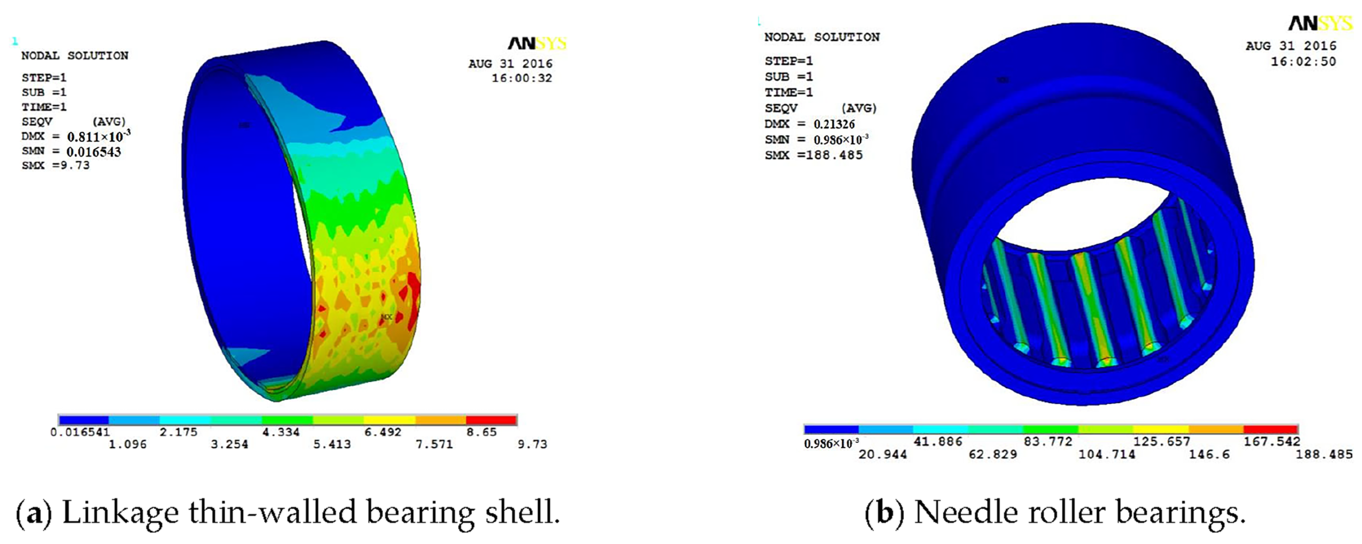
As it is necessary to ensure equal masses of pistons at all levels as much as possible, and the bore of the first-stage cylinder is larger, the static strength is calibrated for the first-stage piston and the second-stage linkage assembly according to the load-bearing capacity of the material and the calculated multiple piston force [16]. First, the 3D solid model is simplified by ignoring features such as chamfers and oil holes. Then, the mesh is divided for the calibration object, and material properties and boundary conditions are also defined to constrain the radial motion of the piston, and the round hole of the big end of the linkage is completely fixed. The piston end is loaded with the maximum value of the multiple piston force, as shown in Figure 5a. The stress distribution nephogram of each component is obtained, as shown in Figure 6, Figure 7 and Figure 8. The contact force area between the needle roller bearing and the primary piston pin is small, and the stress amplitude at the location where the two are in contact is large. The large-diameter first-stage piston is made of aluminum due to the demand for a lightweight piston. The strength is ensured mainly by internal gussets. The location where the gussets are connected to the pin bore is prone to stress concentration. The tension–compression stress will exist cyclically during the operation of the linkage. It is necessary to pay attention to the stress concentration in the transition fillet of the linkage body.
Calculated by finite element analysis, the maximum stresses of the above parts do not exceed the ultimate strength of the corresponding materials. The specific values and parts with the maximum occurring stress are shown in Table 2.

2.4. Modal Analysis of Four-Star-Type Crank Linkage

Modal analysis is an important element in the dynamic design of a structure. It is the basis for the finite element analysis of the structure. By combining theoretical modal analysis methods with experimental modal analysis methods, the problems related to the dynamic design of complex structures can be solved to a large extent. The structural modal is an inherent property of the structure, which is independent of the external load but related to the external constraints [17]. Modal parameters mainly include inherent frequency, modal shape, modal stiffness, etc. In order to analyze the vibration response of a structure, it is necessary to understand the inherent frequency and modal shape of the structure.

2.4.1. Modal Equations

The differential equation for vibration is as follows:
M X ¨ + C X ˙ + K X = F
where M , C , and K are the mass, damping, and stiffness matrices, respectively. X ¨ , X ˙ , and X are the acceleration, velocity, and displacement matrices of the reference point, respectively. F is the load matrix.
The effect of damping C on the mode shape and modal frequency is negligible, and for the free modal analysis, we utilize F = 0 , and we obtain the following:
M X ¨ + K X = 0
When the structure is vibrating freely at the intrinsic frequency, let X = A sin ω i t + φ , and we obtain the following:
K ω i 2 M A = 0
The equation has a non-zero solution; then, K ω i 2 M = 0 . The characteristic root ω 0 is the intrinsic frequency of the structure. The characteristic vector A j is the corresponding vibration mode. As some of the structures are irregular in shape, it is difficult to find the analytical solution using the differential equation. The solution is usually performed by the finite element method and verified by experiments.

2.4.2. Modal Analysis

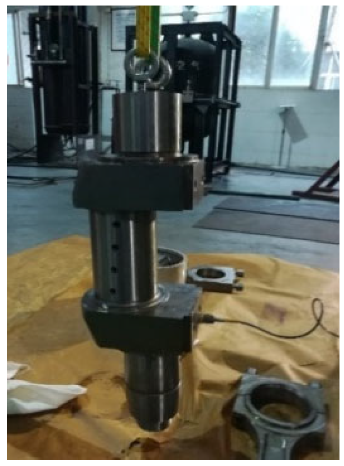
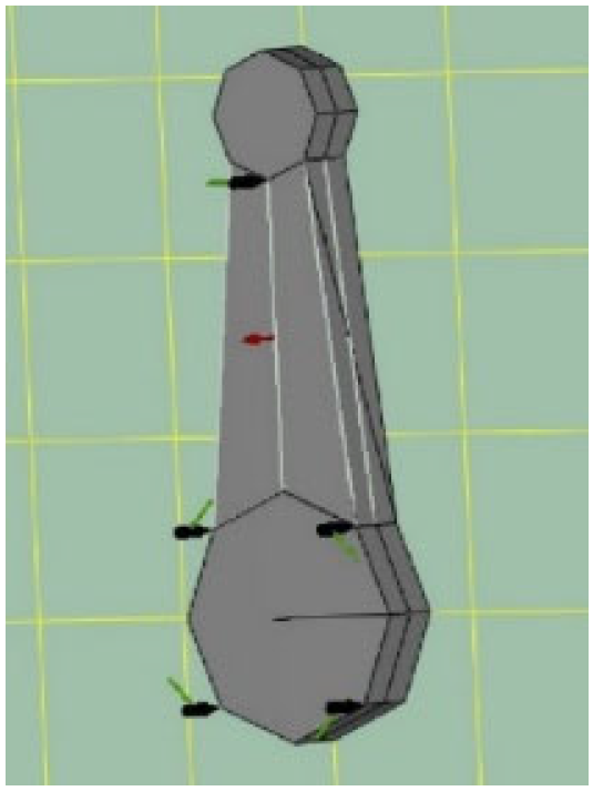
Modal analysis includes free modal analysis, installed modal analysis, and operational modal analysis. Free modal analysis is usually used to verify the reasonableness of the finite element model. It is the basis for further finite element analysis. In this paper, the free modal analysis of the crankshaft is carried out. The free mode of the crankshaft is measured by multi-point knocking and single-point response. Figure 9 shows the crankshaft free-suspension state. There are two hooking bolt mounting holes on the end face of the crankshaft, and the motorcycle elastic band is used to lift it with the hooking bolt. Figure 10 shows the knock point and acceleration sensor arrangement. The arrows show the sensor mounting direction. The black dot hammer indicates the hammering point and direction, and a total of 27 points are hammered. Each point is struck three times. The number of strikes must be recalculated in case of consecutive hits. Therefore, the hammering method requires some operational experience. In the finite element free modal analysis, the material properties are defined as follows: density is 7820 kg/m3, modulus of elasticity is 2.1 × 10¹¹ N/m3, and Poisson’s ratio is δ = 0.266 . The mesh is divided into tetrahedral elements. The mesh is refined at the rounded corners and round holes. The number of mesh nodes is 195,652, and the number of divided cells is 136,554. In addition, 10 Hz–2000 Hz is chosen as the analysis bandwidth. The comparison of the modal vibration patterns is shown in Figure 11. In the frequency band of 10–2000 Hz, the crankshaft has only two bending modes. The bending directions of the modes can be aligned. The first-order resonance frequency is 1.5% different. The second-order resonance frequency difference is 1.9%. The error is controlled within 2% due to the influence of casting process and the lubricating oil left in the oil hole, which can meet the calculation requirements.
In the process of finite element analysis, it is generally necessary to make appropriate simplifications to the model. One is to facilitate meshing, and the other is to save computer resources. In order to discuss the effect of the degree of simplification on the modal frequency, the simplification process of the model is shown in Figure 12. Finite element modal analysis is carried out for the original 1:1 model, then the model with rounded holes and chamfers is removed, and the model with peripheral details is removed for the three degrees of simplification, respectively. The analysis results are shown in Table 3. The errors of the first two orders for the de-rounded hole and chamfered model are 2.6% and 1.9%, respectively. The number of finite element units of the final simplified model differs from the original 1:1 model by a factor of nearly 10. The difference between the first-order inherent frequency of the simplified model and the experiment is 6.6%, and the second-order inherent frequency is 5.6%. The error is larger than that of the 1:1 model, but it can basically meet the general calculation requirements.
The linkage is freely suspended, as shown in Figure 13. First, we hang the small end of the linkage freely by the elastic rope, then tighten the linkage bolt at the large end of the linkage. The test bandwidth is 10–2000 Hz. It also adopts the method of multi-point knocking and single-point response, and the schematic diagram of hammering and response points is shown in Figure 14.
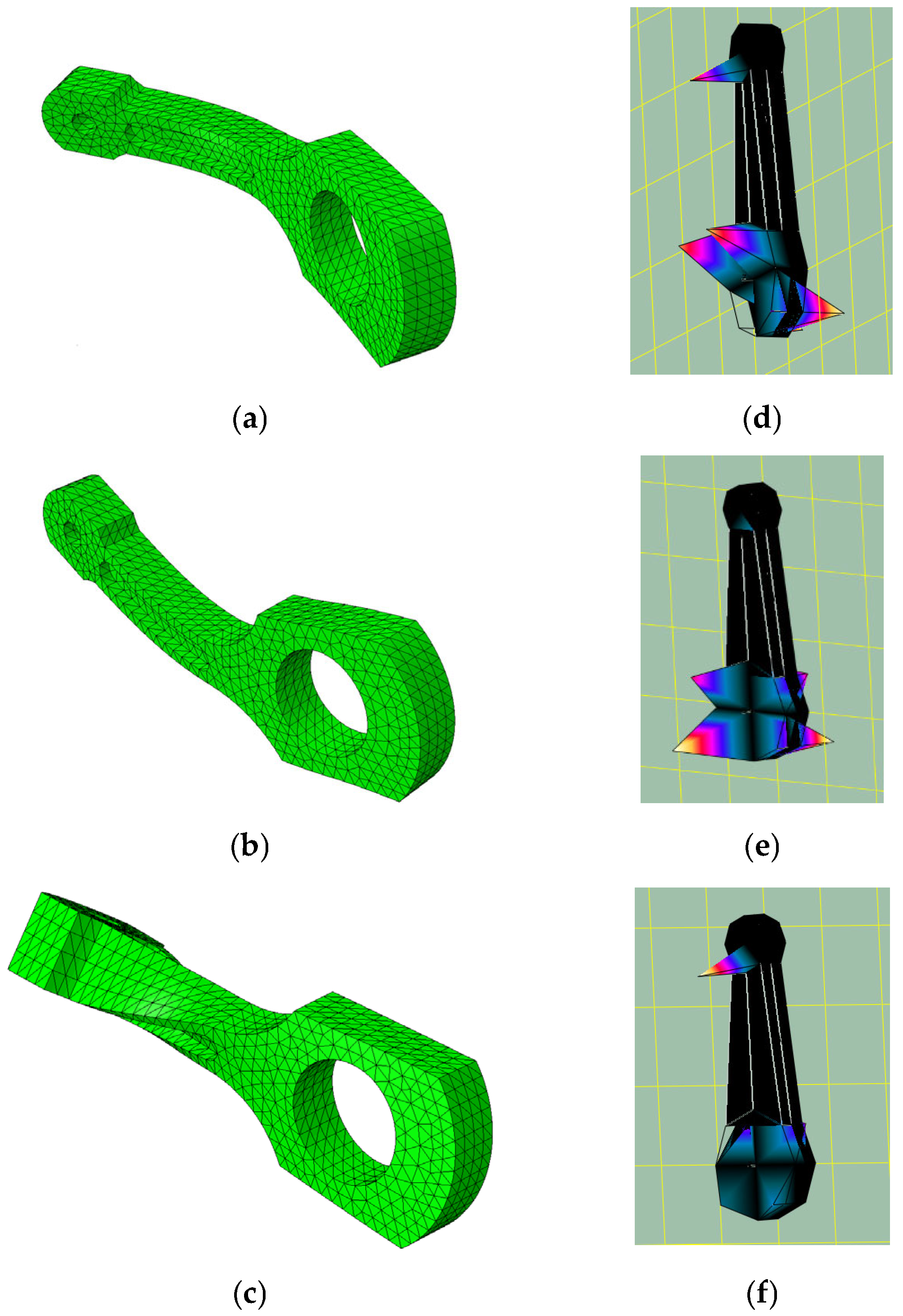
A comparison of the modal vibration shapes of the linkages is shown in Figure 15. The difference of modal frequencies in the first three orders is 11.5%, 8.6%, and 3.5%, respectively. The vibration shapes are axial bending, radial bending, and torsion, respectively. By comparing the error data, it can be found that the lower-order inherent frequency error is larger than the higher-order inherent frequency, which indicates that the lower-order inherent frequency of the finite element calculation results of the linkage assembly is more prone to larger errors. The big end of the linkage is two parts put together, and there are also additional parts such as the bearing and the linkage bolt. The finite element analysis directly calculates the linkage. The peripheral details are also simplified to a certain extent, and thus, the modal calculation error is larger than that of a single crankshaft.

3. Simulation of Mechanical Characteristics of Four-Star-Type Crank Linkage

3.1. Ideal Four-Star-Type Crank Linkage

3.1.1. Simulation Calculation of Flexible Crank Linkage

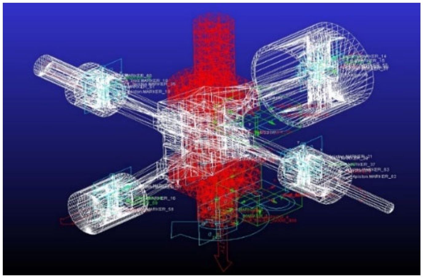
The mutual coupling of rigid motion and flexible deformation of the members is an important and difficult problem in the study of dynamics of flexible multi-body systems. The four-star-type crank linkage is a multi-body dynamics system, and the barycenter of each member is selected as the respective kinematic reference system, and the member deformation is handled according to the linear method. The coordinate axes of the kinematic reference system are always coincident with the inertial principal axes of the deformed members. Thus, the deformation motion of the member is coupled to the rigid mode, which is conducive to improving the convergence and accuracy of the multi-body dynamics analysis. The gas force on the piston of Figure 3 is subjected to a SPLINE curve constructed in ADAMS and loaded to the barycenter on the piston. The direction is along the direction of piston motion when the gas expands, and by default, the gas force applied to the piston at each level is balanced, and the phase between two adjacent pistons is 90° apart. The flexible crankshaft dynamics model is shown in Figure 16.
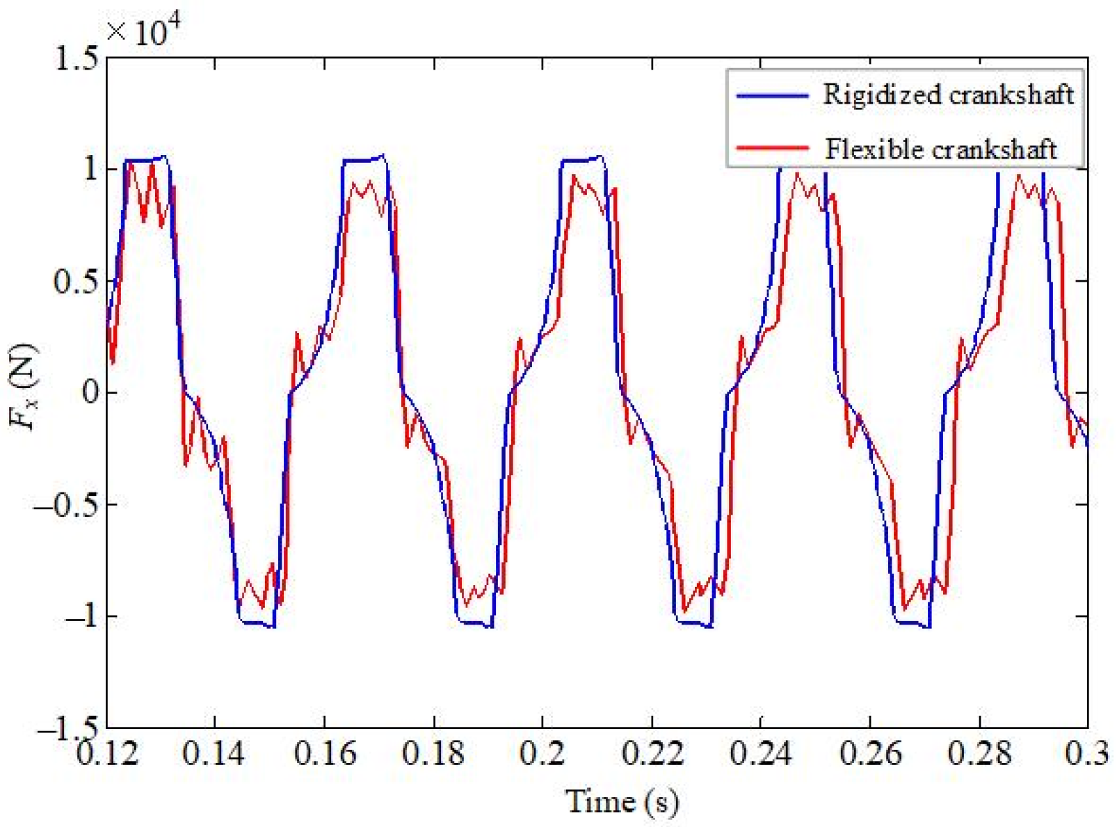
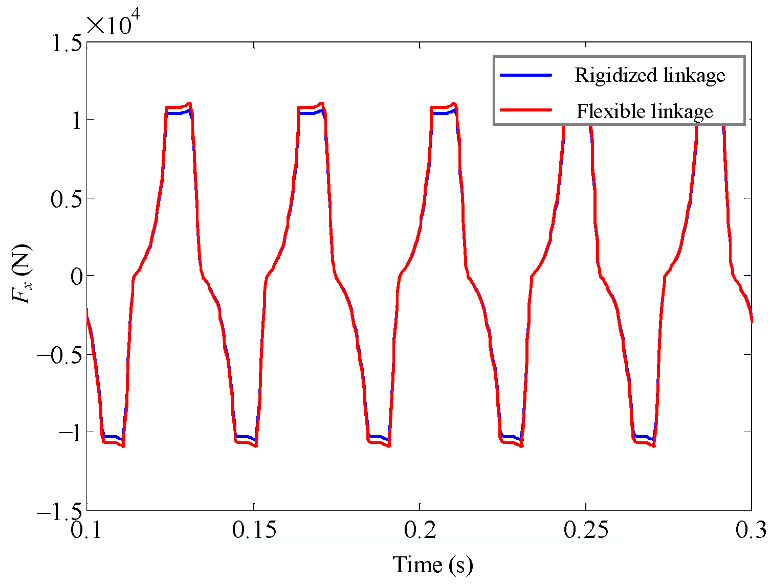
Tetrahedral elements are used to flex the crankshaft and linkage, respectively. The crankshaft is divided into 3574 elements. The primary and secondary linkages are divided into 980 elements. The third- and fourth-stage linkages are divided into 1056 elements. The crankshaft alone is flexible enough to obtain the main shaft force bearing situation, as shown in Figure 17. The four linkages are flexed separately to obtain the main shaft force bearing situation, as shown in Figure 18. From the comparison of the two figures, when the crankshaft is flexible, the main shaft bearing force fluctuates to a certain extent. When the linkage is flexible, the main shaft bearing force only increases slightly in magnitude, which means that the crankshaft is closer to the flexible body than the linkage. In general, neither the crankshaft flexibilization nor the linkage flexibilization changes the trend of the excitation force of the main shaft bearing. It is only the magnitude that deviates to some extent. The crankshaft flexibility is generally considered only in multi-row reciprocating compressors. The crankshaft stiffness of the four-star-type air compressor is large, and the rigid-body dynamics analysis that can meet the general calculation requirements.

3.1.2. Simulation Calculation of Crank Linkage with Friction for Kinematic Pair

As the analysis in the previous section shows, the crank linkage flexibility does not affect the trend of the main shaft bearing force. Therefore, a rigid-body model is used in this section to investigate the effect of friction on the main shaft bearing excitation force. The ADAMS built-in IMPACT collision function is used to define the kinematic pair contact between the big end of the first-stage linkage and the crankshaft. The other kinematic pairs are kept in ideal condition. Meanwhile, the parameters of the Coulomb friction force model are selected. The expression of the contact force is calculated as follows:
F n = K δ n + step δ , 0 , 0 , δ max , C max d δ d t δ > 0 0 δ 0
step δ , 0 , 0 , δ max , C max = 0 δ 0 C max δ δ max 0 < δ < δ max C max δ δ max
where K is the collision stiffness, δ is the penetration depth of the kinematic pair contact surface, δ max is the maximum penetration depth of the kinematic pair contact surface, d δ / d t is the relative velocity of the collision, n is the force exponent, and C is the damping coefficient. The selection of each parameter is shown in Table 4.
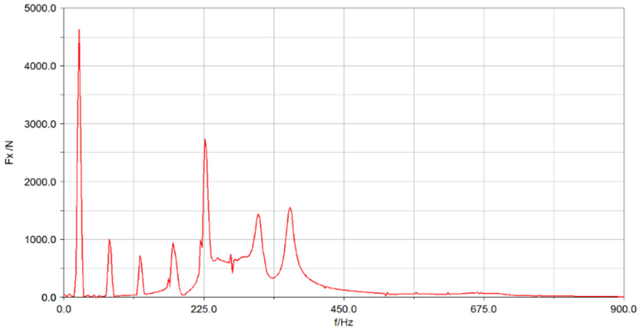
By reasonably setting the relevant parameters of the contact model, the barycenter of the piston is loaded with the gas force applied to the piston in Figure 4 according to the phase relationship, and by default, the pistons of all levels are subjected to equal forces, and there is only a difference in phase. The multi-body dynamics simulation is carried out to obtain the force on the main shaft with and without friction at the big end of the first-stage linkage, as shown in Figure 19 and Figure 20, respectively.
As can be seen from the figure, the presence of friction has basically no effect on the crankshaft fundamental frequency excitation force. However, it will greatly broaden the excitation frequency band. The friction of the kinematic pair brings the excitation energy in the middle and high frequencies. When the friction is not considered, the peak excitation force is obvious near 225 Hz. When the friction is considered, the excitation peak at this location is suppressed. However, the amplitude of the excitation force in the nearby frequency band is increased. The line spectrum of air compressor vibration energy has more components, and the moderate friction can control the line spectrum energy and reduce the air compressor vibration to some extent.

3.2. Non-Ideal Four-Star-Type Crank Linkage

3.2.1. Dynamic Characteristics of Four-Star-Type Crank Linkage with Clearance

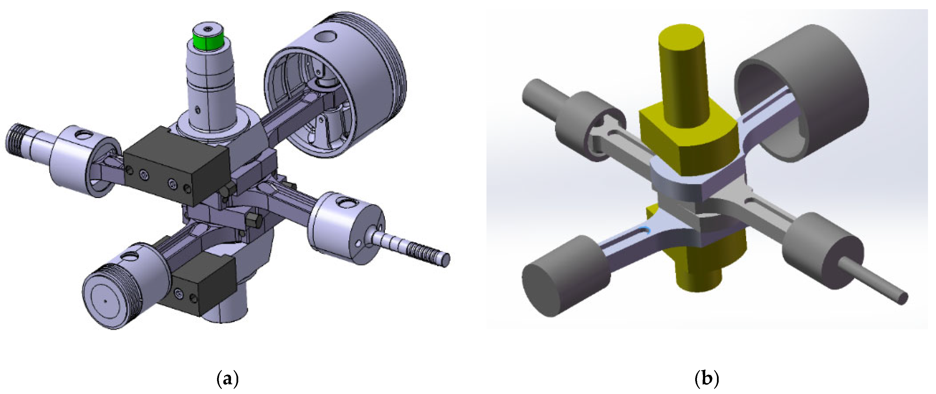
In order to facilitate the adjustment of the clearance values, the four-star-type crank-linkage structure was simplified. The simplified model is shown in Figure 21. The variation of the main shaft bearing force with the balance mass is shown in Figure 22a. The frequency domain diagram of the force applied to the crankshaft rotating pair in the direction of piston motion with the optimum amount of balance mass obtained is shown in Figure 22b. The simplification process brings about a change in the volume of the structure and the position of the barycenter. To some extent, the second-order inertia forces are excited, but they are still lower than the third-order inertia forces. The air compressor development process also cannot avoid the problem of center of gravity and mass deviation due to the non-uniform density of the casting.
In the actual operation of the machinery, the driving torque needs to change with the load in order to ensure the stability of the rotational speed due to the clearance, friction, and external forces. It is difficult to stabilize the rotational speed by controlling the driving force because of the existence of friction, sudden changes in the load, and a certain degree of randomness. In order to reduce the speed fluctuation, a flywheel is usually connected to the crankshaft, whose rotational inertia is relatively large. In the process of flywheel rotation, the surplus power is saved in the form of kinetic energy, and when the load changes, the energy is absorbed or released to achieve the purpose of stabilizing the speed.
The simulation process directly constrains the rotational speed to a constant value so that the driving torque will change. The operating condition is 1480 r/min. The clearance between the crankshaft and first-stage linkage is set to 0.1 mm. The speed is set to the rated value within 0.1 s by using the step function. The drive torque power in the ideal connection and clearance kinematic pair state is obtained, as shown in Figure 23. The shorter the start-up time, the larger the start-up torque required. In 0.1 s, the required starting torque is larger, and the driving power is gradually stabilized after starting. In the ideal state, the final value of torque power amplitude is stable at 819 w. When there are clearances and friction in the kinematic pair, the power of the torque fluctuates transiently, far beyond the ideal connection. The torque power amplitude is at 6711 w without considering the transient fluctuation due to the balancing effect of the flywheel.
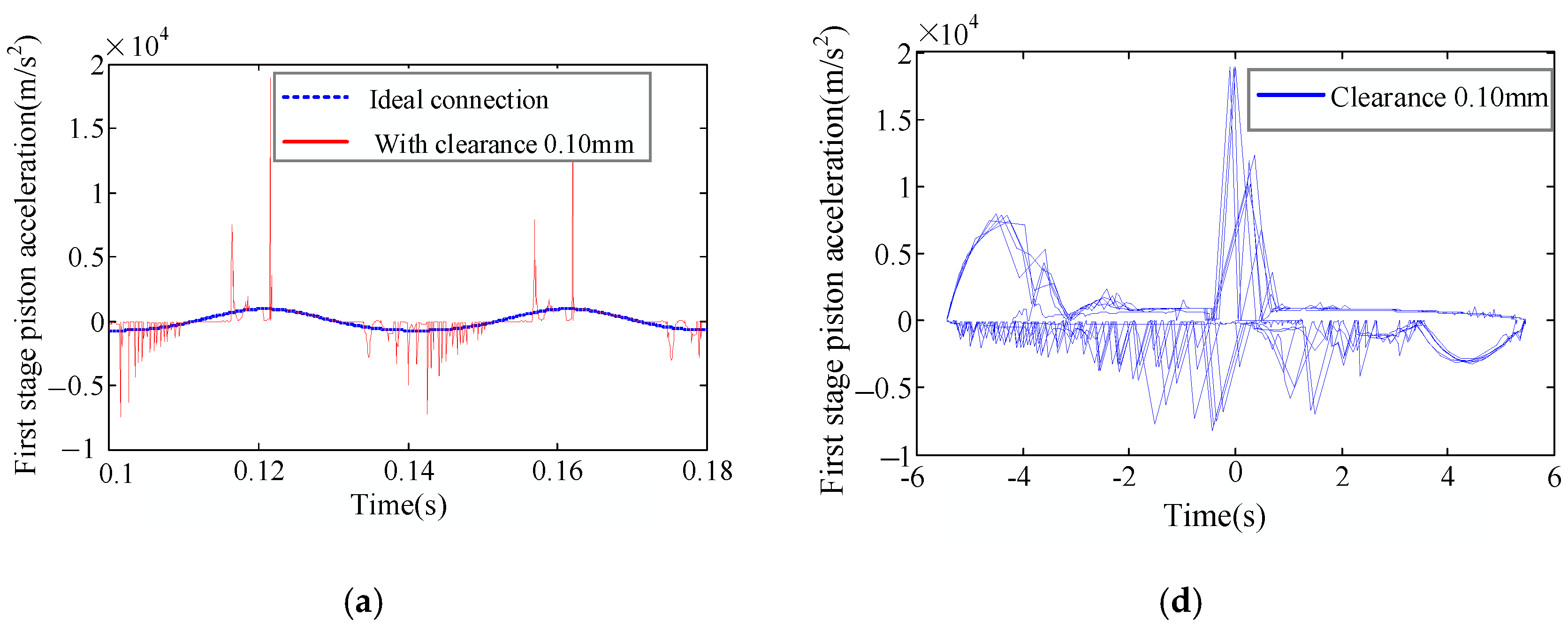
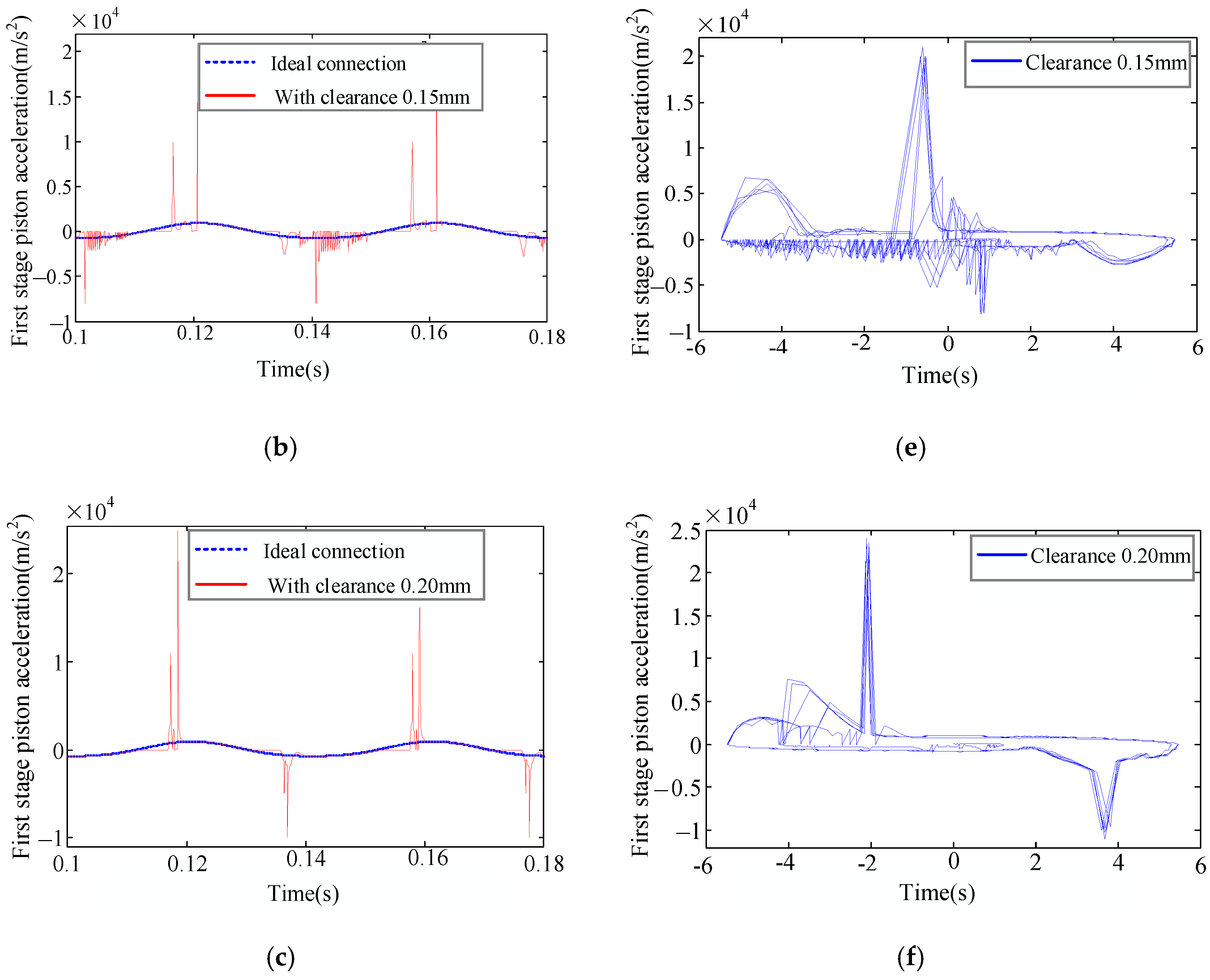
The rated speed of this type of air compressor is 1480 r/min. According to the relevant technical requirements of submarine air compressor, the wear clearance of the kinematic pair generally does not exceed 0.1 mm, and the installation clearance of the crankshaft and linkage is 0.1 mm. Therefore, the values of 0.10 mm, 0.15 mm, and 0.20 mm are taken as the crankshaft, linkage, and kinematic pair clearances, respectively, for simulation calculation. The modified contact-collision force model is embedded into the contact definition of the crankshaft and linkage revolving pair. To control other variables, only the clearance between the first-stage linkage and the crankshaft is considered, and the other kinematic pairs are defined as ideal connections. Take 0.1 mm clearance as an example. The corresponding dynamics model can be established by expanding the radius of the big end of the first-stage linkage by 0.1 mm and reassembling the four-star-type crank-linkage structure. The time-domain diagrams of acceleration of the first-stage piston with different clearances are shown in Figure 24a–c. The sudden change of acceleration peak is triggered at the upper and lower stops of the piston motion, and the larger the clearance, the higher the acceleration amplitude, and the lower the number of contact collisions. The velocity-acceleration phase diagrams of the first-stage piston with different clearances are shown in Figure 24d–f. The larger the clearance size is, the more concentrated the phase diagram trajectory is.
The clearance value is 0.1 mm, and the speed conditions are set to 148 r/min, 740 r/min, and 1480 r/min. The time-domain accelerations at different rotational speeds are shown in Figure 25a–c. The higher the rotational speed, the higher the frequency of contact collision. It shows high-frequency oscillation, and the corresponding acceleration amplitude is larger. Since the time-domain acceleration is not symmetrical about the horizontal line with vertical coordinate 0, the positive acceleration is slightly higher than the negative acceleration. Thus, the peak positive acceleration is higher than the negative one, but the number of collisions is lower than the negative one. The acceleration-velocity phase diagram of the first-stage piston at different rotational speeds is shown in Figure 25d–f. The higher the rotational speed, the larger the amplitude of the phase diagram trajectory, and the more concentrated the phase trajectory.

3.2.2. Mechanical Characteristics of Four-Star-Type Crank Linkage with Clearance

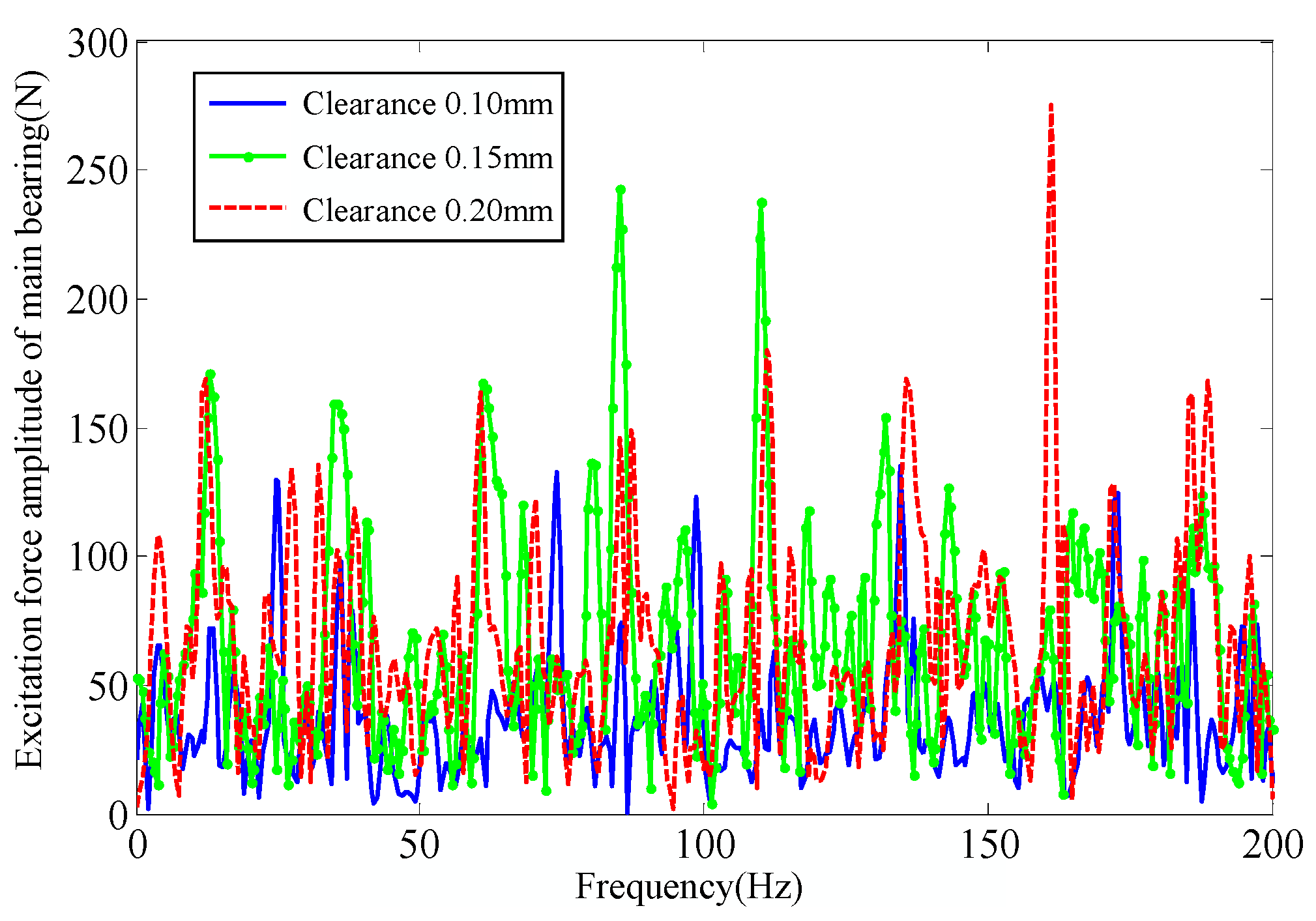
The rotational speed of the crankshaft is set to a constant value. The radii of the big end of the first-stage linkage are enlarged by 0.10 mm, 0.15 mm, and 0.20 mm, respectively, and the other kinematic pairs are set to the ideal connection. The excitation force in the X direction of the main shaft bearing is shown in Figure 26. Compared with Figure 22b, the presence of clearance makes the excitation force show the characteristics of broad frequency excitation, and the amplitude is nearly twice the ideal condition. The larger the clearance, the larger the corresponding excitation force amplitude. At the same time, the excitation force amplitude is located at different frequency values. It is because of the frequency-shifting characteristics of the excitation force amplitude in the clearance state, which makes the balance of the main shaft bearing excitation force in the clearance state very difficult, and the size and location of the clearance is also difficult to determine clearly. At present, the balance of the main shaft bearing excitation force is calculated based on the ideal kinematic pair connection.
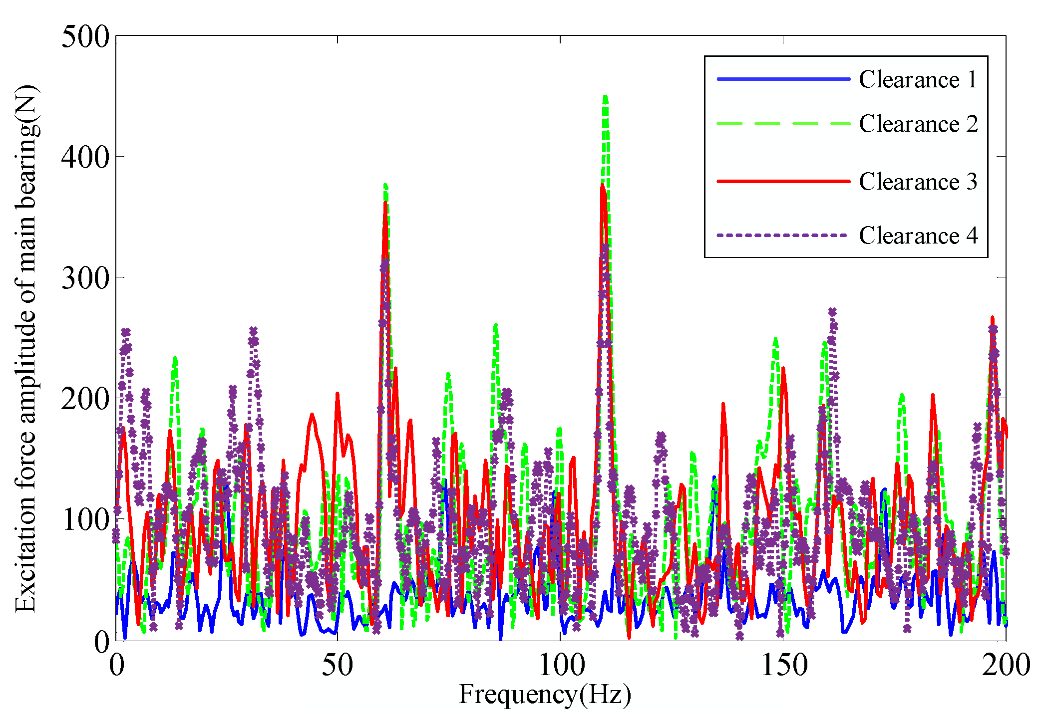
Next, we expand the radius of the big end of the first- to fourth-stage linkage by 0.1 mm, respectively, and construct four working conditions: (1) the big end of the first-stage linkage with clearance; (2) the big end of the first- and second-stage linkage with clearance; (3) the big end of the first, second and third linkage with clearance; and (4) the big end of the first-, second-, third-, and fourth-stage linkage with clearance. The excitation force amplitude under the four working conditions is shown in Figure 27. The excitation force amplitude of single clearance is the smallest. When the big end of the first- and second stage linkage contains clearance, the excitation force amplitude in X direction of the main shaft bearing is the largest. Case 3 is smaller than case 2. Case 4 is second to case 3. The crankshaft-linkage kinematic pair clearance corresponding to the Y-phase moving piston can reduce the main bearing X-directional excitation force. The relief effect is better when the big end of the third- and fourth-stage linkage clearance exists at the same time. In terms of low-frequency excitation force (below 10 Hz), the more clearance, the higher the excitation force amplitude.

4. Experimental Study of Four-Star-Type Crank Linkage

4.1. Construction of the Test Bench

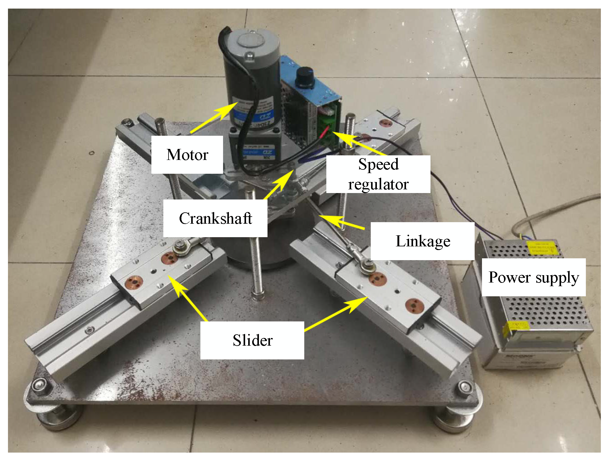
The test bench of four-star-type crank linkage is shown in Figure 28. The test system can be divided into four parts: one is the bracket part, mainly for erecting motors and linear guides of different heights. The second is the star crank-slider mechanism, which is mainly designed for the clearance size and position. Third is the motor and speed regulator, mainly including the selection of the motor and speed regulation scheme. Fourth is the test data acquisition part using the acceleration sensor to obtain the acceleration of the corresponding measurement points in real time.
The support part mainly includes the foot support, base plate, upper plate, and threaded rod. In order to facilitate the installation of the crank linkage and the observation of the test phenomenon, the upper plate adopts a highly transparent acrylic plate. The base plate is supported by four feet. The upper and lower plates are supported by four M12 threaded rods with a length of 25 mm. The height of the upper plate can be adjusted by bolts and gaskets. Four guide rails are supported by two M5 threaded rods. The height difference is adjusted by nut and gasket. A nut plus a gasket has a height of 5 mm, the same as the height difference between the two columns of linkages. The bottom of the guide rail is supported by a gasket with an outer diameter of 50 mm.
The four-star-type crank-slider mechanism was mainly assembled by outsourcing standard parts. It is mainly composed of eight fisheye bearings, nine M6 threaded rods, two crank arms, four sliders, a flywheel, and several nuts and gaskets. The two crank arms and the screw are secured with nuts and gaskets. The fisheye bearings were snapped onto the crank screws before assembly. The bearings were separated by a nut to prevent collision during the movement of the linkage. Two fisheye bearings and the screw were butted together at both ends to form the linkage. The bearing ends were held in place by nuts and gaskets. The length of the linkage could be adjusted by intercepting different lengths of the screw. Threaded holes were punched in the slider. The inner ring of the fisheye bearing at one end of the linkage was pressed against the guide rail by bolts and gaskets. A file and sandpaper were used to polish the inner ring and outer ring of the fisheye bearing until the kinematic pair clearance met the established requirements.
Considering the effect of rotational speed on the acceleration response of the slider, the test required the motor speed to be adjustable. A direct current (DC) motor has large starting torque and good speed regulation performance compared with an alternating current (AC) motor. Therefore, this test adopted a Zhongda Z2D40-24GN DC motor with corresponding speed regulator. The rated voltage of the motor is 24 V, the rated power is 40 W, the rated speed is 1800 r/min, and the speed range is 0~1800 r/min. In order to achieve enough torque and make the maximum test speed as close as possible to the full load of the motor, the motor was equipped with a speed reducer with a speed ratio of 3, so the rated output speed is 600 r/min. The output shaft is an 8 mm offset milling shaft, and it was connected through the top wire and crankshaft inside the round hole in the crank arm.
Low-frequency piezoelectric acceleration sensors were used for vibration data acquisition. The model is NIELL-TECH: CAYD115V-100A, and the sensitivity is 100 mv/g. The sensor is highly insulated and pressure-resistant, and the overall sealing design can be applied to harsh environments. A 56-channel LMS acquisition card was used for data acquisition, with the bandwidth set to 51,200 Hz, the number of line spectrum roots set to 65,536, and a frequency resolution of 0.78 Hz. The data acquisition system is shown in Figure 29. A total of seven measurement points were arranged. The four slider ends were arranged with measurement points 1–4, the base plate was arranged with measurement point 5 in the vertical direction, the upper plate was arranged with measurement point 6 in the vertical direction, and the center position of the upper plate was arranged with measurement point 7 in the direction of slider movement at the edge of the plate.

4.2. Analysis of Experimental Data

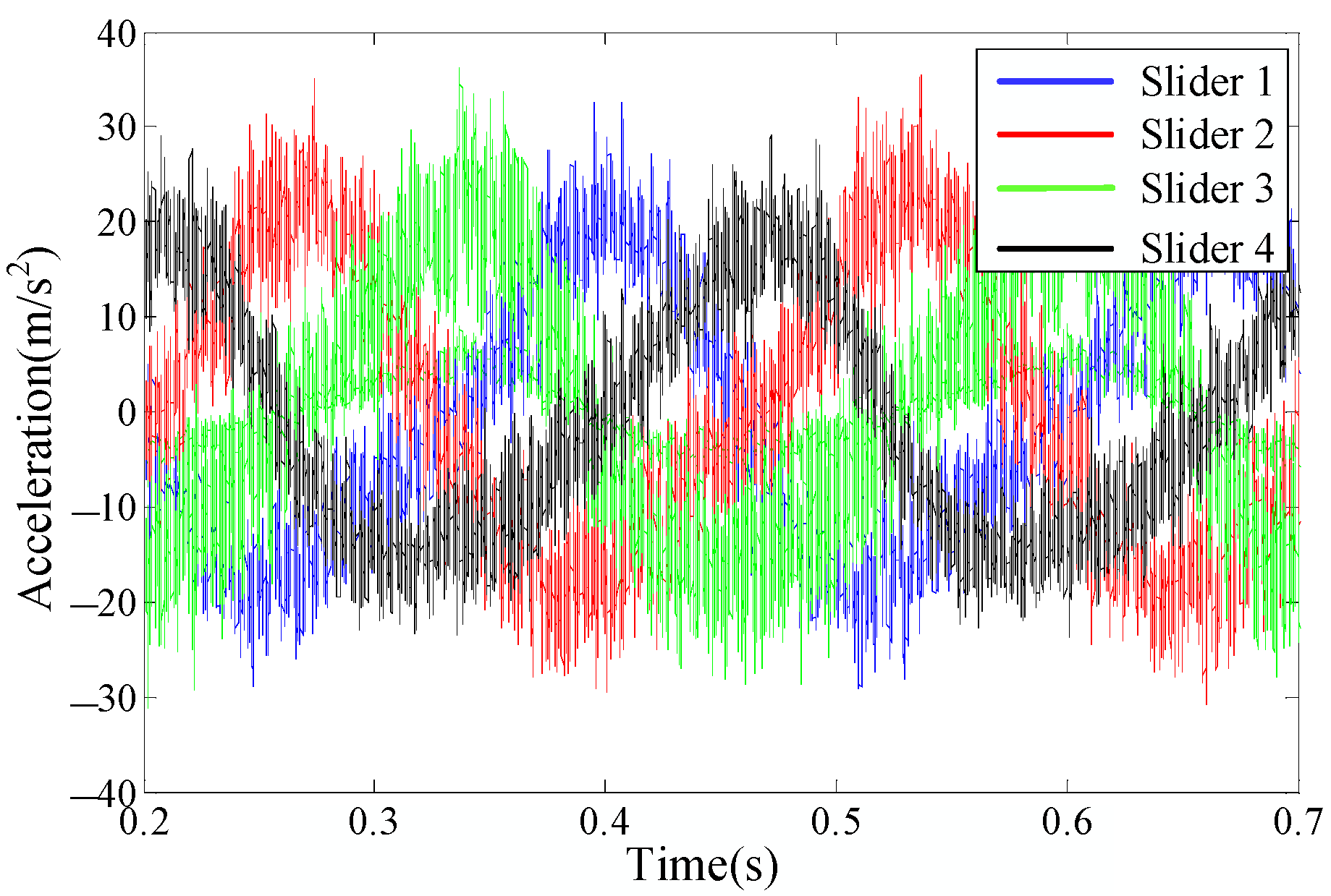
The rated speed output of the purchased motor is 600 r/min. The output speed at full load with load is only 240 r/min. The acceleration of the four sliders at full load under normal installation is shown in Figure 30. As the test bench was built manually, threaded connections were used in many places, and no professional instruments were used for local adjustments, for example, alignment and leveling. From the figure, it can be found that the acceleration signal has serious distortion in the time domain. Therefore, this section focuses on the phase diagram to compare the test results and analyze the vibration acceleration of the bench.

4.2.1. Effect of Clearance Size on the Dynamic Response of the Mechanism

In the dynamic response analysis of the mechanism, the existence of clearance is usually ignored, and the clearance of the kinematic pair is idealized. In engineering practice, the clearance in the kinematic pair is formed by the machining of the parts, the assembly of the kinematic pairs, and the wear during operation, which cannot be avoided. The collision force caused by the clearance not only consumes the energy of the mechanical system but also causes the vibration, noise, and dynamic output of the system. In high-speed, heavy-duty machinery, the clearance will make the elements of the kinematic pair violent during contact collision. The supporting reaction force of the kinematic pairs will rise to more than ten times the normal value, which makes the deformation of the components increase, the wear intensify, and the vibration and noise become greater, seriously affecting the efficiency and service life of the mechanism.
A file was used to polish the inner ring of the fisheye bearing. Then, the surface was polished with sandpaper to create a wear clearance. Due to the irregularity of the wear process, only a qualitative analysis of the test results was made. The maximum wear was about 0.1 mm. The working conditions were divided into large wear, medium wear, and no wear. The motor speed was 240 r/min. The slider 1 was used as the object of study. The acceleration–velocity phase diagrams for different clearance sizes are shown in Figure 31. In general, the phase trajectories are all an ellipse. With the increase of wear, the acceleration amplitude increases, while the area of the center of the ellipse decreases, and the shape becomes more regular.

4.2.2. Effect of Rotational Speed on the Dynamic Response of the Mechanism

Considering the existence of mounting clearance in the test bench itself, the installation state of the first-stage linkage fisheye bearing without wear is taken as a reference. The acceleration–velocity phase diagrams of the first-stage slider at different rotational speeds under 80 r/min, 160 r/min, and 240 r/min working conditions are shown in Figure 32. As can be seen from the figure, the phase diagram trajectory is relatively turbulent at low rotational speed. As the rotational speed increases, the phase trajectory becomes more and more concentrated. The increase of rotational speed increases the slider acceleration amplitude and reduces the chaos of the system.

4.2.3. Analysis of the Vibration Response of the Bench

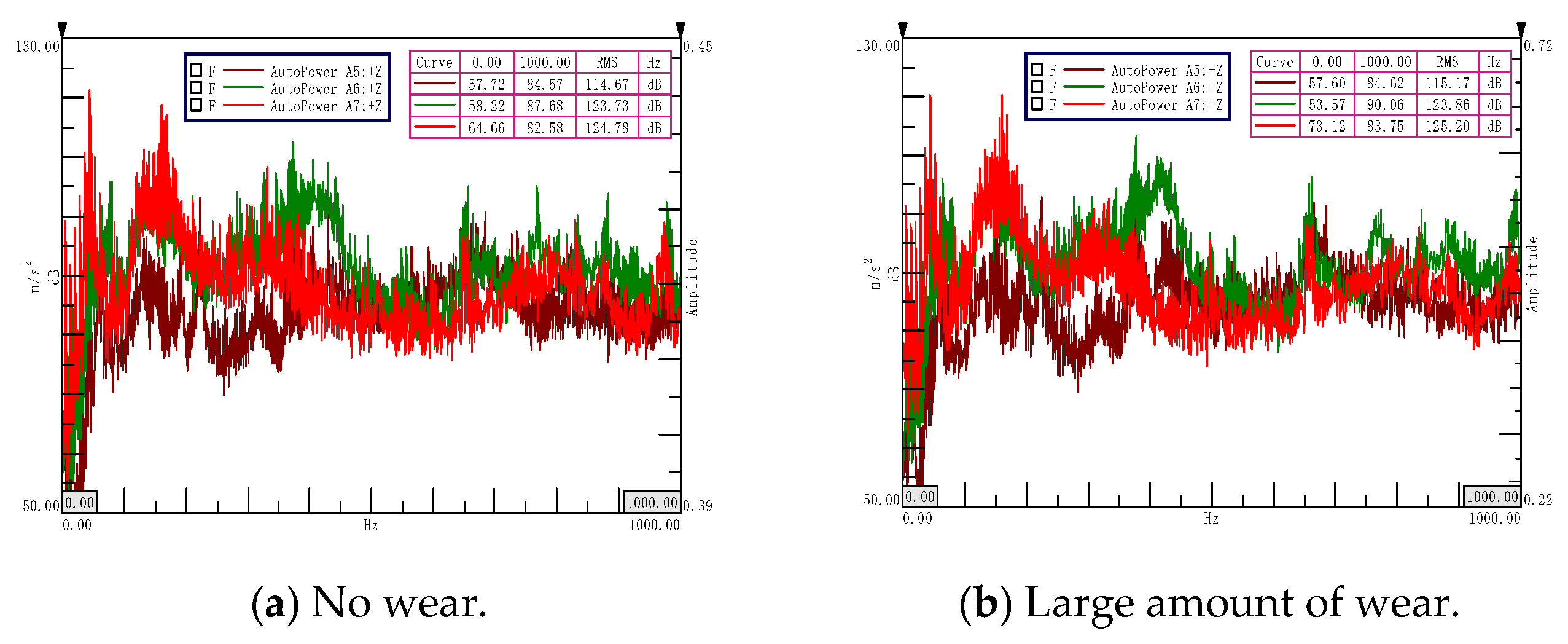
Vibration measurement points no. 5, 6, and 7 measure the base plate vertical vibration, the upper plate vertical vibration, and the vibration in the direction of the first-level slider movement of the upper plate, respectively. The specific locations of the measurement points are shown in Figure 31b. The frequency-domain diagram of vibration acceleration at each measurement points from 0 to 1000 Hz at 240 r/min is shown in Figure 33. In the 0–300 Hz frequency band, the horizontal acceleration of the upper plate > the vertical acceleration of the upper plate > the vertical acceleration of the base plate. After 300 Hz, the vertical acceleration of the upper plate is higher than the horizontal acceleration overall. However, from the whole frequency band (0–1000 Hz), the horizontal acceleration level is 1.05 dB higher than the vertical one, which indicates that the whole spectral energy is relatively concentrated in the low-frequency band. Under the same conditions, the vibration control effect of suppressing the low-frequency vibration of the bench will be relatively obvious in the wide frequency band.
Comparing the two cases of no wear and big wear, the existence of clearance will increase the vibration of the bench. The increments of vibration acceleration levels at measurement points 5, 6, and 7 are 0.50 dB, 0.13 dB, and 0.42 dB, respectively. The acceleration increase of the base plate is obvious, mainly because the flywheel is installed near the base plate. In addition, the bearing mounting hole of the base plate has a certain clearance, while the other end of the crankshaft is directly connected to the motor output shaft, and the restraint is more solid. The presence of the clearance mainly affects the horizontal movement of the slider; thus, there is a 0.42 dB increment in the horizontal vibration acceleration level of the upper plate.
The speed regulation interval between 80 r/min and 240 r/min is divided into five equal parts and marked on the regulator to obtain the vibration acceleration levels in the 0–1000 Hz frequency band for measurement points 5, 6, and 7 under six operating conditions as shown in Figure 34. With the increase of motor speed, the vibration acceleration level generally shows a linear increasing trend. The difference between vertical and horizontal acceleration of the upper plate has a process of first decreasing and then increasing. The presence of the clearance accelerates the appearance of the minimum difference. The horizontal and vertical accelerations of the upper plate are significantly higher than those of the base plate. The presence of the clearance makes the acceleration level of the base plate more linear with the working condition in the low-speed section.

5. Conclusions

The crank-linkage mechanism is the main moving part in the operation of a reciprocating air compressor. This paper focuses on the kinematic characteristics, stresses, and mechanical behavior of the four-star-type crank-linkage mechanism. The main findings are summarized as follows:
(1)
From the viewpoint of the motion relationship, there are two moments in a rotation cycle of the four-star crank linkage where the acceleration of each piston is exactly equal in magnitude. From the point of view of the force, the four-star crank linkage has a good balance of the second-order reciprocating inertia force. The first-order reciprocating inertia force and the second-order reciprocating moment of inertia mainly exist. By calibrating the static strength of the first-order piston, first-order piston pin, second-order linkage, linkage needle roller bearing, and thin-walled bearing liner of the linkage, the stress-concentration areas were found;
(2)
The modal calculation results of the simplified crankshaft finite element model are closest to the experiments. The computational efficiency of the simplified crankshaft finite element model is greatly improved. However, the error is about two times the original finite element model. Compared with the experimental modal, the modal frequency error before and after simplification can be controlled within 7%. The linkage is a combined part, and the finite element modal analysis treats it as a single part for modal analysis. In addition, the local details are simplified to obtain the finite element modal frequency calculation error, which is significantly increased compared with the crankshaft;
(3)
The crankshaft is more complex than the linkage in terms of forces. The first-order inherent frequency of the crankshaft is significantly higher than the first-order inherent frequency of the linkage. However, the analysis results of rigid–flexible coupling dynamics model show that the crankshaft is closer to a flexible body compared to a linkage. The rigid-body dynamics analysis can meet the general calculation requirements due to the small axial length of crankshaft, high stiffness, and high inherent frequency;
(4)
The presence of friction in the revolving pair will suppress some of the resonance peaks. However, it will broaden the excitation frequency band and excite high-frequency vibration. For a power machine with a distinct line spectrum, such as an air compressor, moderate friction can attenuate the vibration acceleration. Friction consumes system energy during the operation of the mechanism, which is beneficial to the attenuation of vibration energy. However, it also generates heat, which has a negative impact on the reliability of the machine operation;
(5)
The larger the clearance, the higher the excitation force on the main shaft bearing of the four-star-type crank linkage, and the frequency corresponding to the amplitude of the excitation force will be shifted. The greater the clearance, the higher the low-frequency excitation force of the four-star-type crank-linkage main shaft bearing. In the wide frequency band, the clearance of the crankshaft-linkage kinematics pair corresponding to the vertically moving piston can reduce the main bearing excitation force in the horizontal direction to some extent. Therefore, the presence of individual clearances is larger than the periodic excitation force of symmetrical distribution of clearances, which is more likely to excite the vibration mechanism.

Author Contributions

Data curation, Y.Y.; Writing—original draft, K.C.; Writing—review & editing, J.L. All authors have read and agreed to the published version of the manuscript.

Funding

This research was supported by National Natural Science Foundation of China (Grant No. 52201389 and 51679245); Natural Science Foundation of Hubei Province (Grant No. 2020CFB148).

Data Availability Statement

Data is unavailable due to privacy or ethical restrictions.

Conflicts of Interest

The authors declare no conflict of interest.

References

  1. Yoon, D.; Choi, Y.J. Underactuated Finger Mechanism Using Contractible Slider-Cranks and Stackable Four-Bar Linkages. IEEE-ASME Trans. Mechatron. 2017, 22, 2046–2057. [Google Scholar] [CrossRef]
  2. Reza, A.; Moslehi, M. Optimal synthesis of an adjustable six-bar path generator mechanism using a cuckoo optimization algorithm. J. Mech. Mater. Struct. 2022, 17, 149–167. [Google Scholar] [CrossRef]
  3. Albaghdadi, A.M.; Baharom, M.B.; Sulaiman, S.A. Tri-planar balancing optimization of a double crank-rocker mechanism for shaking forces and shaking moments reduction. Proc. Est. Acad. Sci. 2021, 70, 286–296. [Google Scholar] [CrossRef]
  4. Zheng, E.; Wang, T.; Guo, J.; Zhu, Y.; Lin, X.; Wang, Y.; Kang, M. Dynamic modeling and error analysis of planar flexible multilink mechanism with clearance and spindle-bearing structure. Mech. Mach. Theory 2019, 131, 234–260. [Google Scholar] [CrossRef]
  5. Doubowsky, S.; Tamir, A. Analytical and experimental study of the prediction of impacts in planar mechanical systems with clearances. J. Mech. Transm. Autom. Des. 1984, 106, 444–451. [Google Scholar] [CrossRef]
  6. Soong, R.C. On the new mechanical press with a planetary gear train. Trans. Can. Soc. Mech. Eng. 2016, 40, 45–58. [Google Scholar] [CrossRef] [Green Version]
  7. Bagci, C. Complete shaking force shaking moment balancing of link mechanisms using balancing idler loops. J. Adv. Mech. Des. Syst. 1982, 104, 482–493. [Google Scholar] [CrossRef]
  8. Arakelian, V.; Briot, S. Simultaneous inertia force/moment balancing and torque compensation of slider-crank mechanisms. Mech. Res. Commun. 2010, 37, 265–269. [Google Scholar] [CrossRef] [Green Version]
  9. Lee, T.W.; Cheng, C. Optimum balancing of combined shaking force, shaking moment, and torque fluctuation in high-speed linkages. J. Mech. Transm. Autom. Des. 1984, 106, 242–251. [Google Scholar] [CrossRef]
  10. Kochev, I.S. General method for active balancing of combined shanking moment and torque fluctuation in planar linkages. Mech. Mach. Theory 1998, 25, 679–687. [Google Scholar] [CrossRef]
  11. Zhou, S.; Shi, J. Optimal one-plane active balancing of rigid tutor during acceleration. J. Sound Vib. 2002, 249, 196–205. [Google Scholar] [CrossRef] [Green Version]
  12. Zhao, J.S.; Wei, S.T.; Ji, J.J. Kinematics of a planar slider-crank linkage in screw form. J. Mech. Eng. Sci. 2021, 236, 1588–1597. [Google Scholar] [CrossRef]
  13. Zheng, E.; Zhu, R.; Zhu, S.; Lu, X. A study on dynamics of flexible multi-link mechanism including joints with clearance and lubrication for ultra-precision presses. Nonlinear Dyn. 2016, 83, 137–159. [Google Scholar] [CrossRef]
  14. Kim, S.H.; Cho, C. Transformation of static balancer from truss to linkage. J. Mech. Sci. Technol. 2016, 30, 2093–2104. [Google Scholar] [CrossRef]
  15. “Piston Compressor Design” Writing Group. Piston Compressor Design; China Machine Press: Beijing, China, 1974. [Google Scholar]
  16. Joonho, H.; Roh, J.; Chunho, C. Design of an efficient swing mechanism for electric swing beds. Trans. Korean Soc. Mech. Eng. A 2022, 46, 923–930. [Google Scholar]
  17. Pradhan, D.; Ganguly, K.; Swain, B.; Roy, H. Optimal kinematic synthesis of 6 bar rack and pinion Ackerman steering linkage. J. Automob. Eng. 2021, 235, 1660–1669. [Google Scholar] [CrossRef]
Figure 1. Kinematic relation of crank linkage.
Applsci 13 08202 g001
Figure 2. The rectangular coordinate schematic diagram of the crank-linkage mechanism. (a) Front view. (b) Top view.
Applsci 13 08202 g002
Figure 3. Acceleration of piston and linkage varies with crank angle. (a) The acceleration curve of the piston barycenter. (b) Angular acceleration curve of the linkage barycenter.
Applsci 13 08202 g003
Figure 4. Variation curve of gas force on piston with crank angle.
Applsci 13 08202 g004
Figure 5. Variation curve of piston force with crank angle. (a) Variation of multiple piston force with crank angle. (b) Variation of piston side thrust with crank angle.
Applsci 13 08202 g005
Figure 6. Stress distribution nephogram of the first-stage piston assembly.
Applsci 13 08202 g006
Figure 7. Stress distribution nephogram of the secondary linkage.
Applsci 13 08202 g007
Figure 8. Stress distribution nephogram of the secondary linkage assembly.
Applsci 13 08202 g008
Figure 9. Diagram of crankshaft free suspension.
Applsci 13 08202 g009
Figure 10. Arrangement of knocking points and acceleration sensors.
Applsci 13 08202 g010
Figure 11. Comparison of modal vibration shapes of crankshaft. (a) Finite element first-order vibration shapes (1336 Hz). (b) Experimental first-order vibration shapes (1356 Hz). (c) Finite element second-order vibration shapes (1461 Hz). (d) Experimental second-order vibration shapes (1489 Hz).
Applsci 13 08202 g011
Figure 12. Simplified process of crankshaft. (a) Original 1:1 model. (b) Removal of round holes and chamfering model. (c) Peripheral detail modification model.
Applsci 13 08202 g012
Figure 13. Diagram of linkage free suspension.
Applsci 13 08202 g013
Figure 14. Schematic diagram of hammering and response points.
Applsci 13 08202 g014
Figure 15. Comparison of modal vibration shapes of linkages. (a) Finite element first-order vibration shape (870 Hz). (b) Finite element second-order vibration shape (1211 Hz). (c) Finite element third-order vibration shape (1630 Hz). (d) Experimental first-order vibration shape (780 Hz). (e) Experimental second-order vibration shape (1115 Hz). (f) Experimental third-order vibration shape (1687 Hz).
Applsci 13 08202 g015
Figure 16. Model of flexible crankshaft dynamics.
Applsci 13 08202 g016
Figure 17. Main shaft bearing force of flexible crankshaft.
Applsci 13 08202 g017
Figure 18. Main shaft bearing force of flexible linkage.
Applsci 13 08202 g018
Figure 19. Main shaft bearing force situation without friction.
Applsci 13 08202 g019
Figure 20. Main shaft bearing force situation with friction.
Applsci 13 08202 g020
Figure 21. Simplified structure of crank linkage. (a) Original model. (b) Simplified model.
Applsci 13 08202 g021
Figure 22. Optimization of crank linkage counterweight. (a) Change in balance weight. (b) Optimal balance weight.
Applsci 13 08202 g022
Figure 23. Time-domain diagram of driving torque power of crankshaft.
Applsci 13 08202 g023
Figure 24. Comparison of dynamic characteristics of different clearance sizes. (a) Time-domain diagram of 0.10 mm clearance. (b) Time-domain diagram of 0.15 mm clearance. (c) Time-domain diagram of 0.20 mm clearance. (d) Phase diagram with 0.10 mm clearance. (e) Phase diagram with 0.15 mm clearance. (f) Phase diagram with 0.20 mm clearance.
Applsci 13 08202 g024aApplsci 13 08202 g024b
Figure 25. Comparison of dynamic characteristics at different rotational speeds. (a) Time-domain diagram of rotational speed 148 r/min. (b) Time-domain diagram of rotational speed 740 r/min. (c) Time-domain diagram of rotational speed 1480 r/min. (d) Phase diagram of rotational speed 148 r/min. (e) Phase diagram of rotational speed 740 r/min. (f) Phase diagram of rotational speed 1480 r/min.
Applsci 13 08202 g025
Figure 26. Excitation force amplitude of main shaft bearing with different clearance sizes.
Applsci 13 08202 g026
Figure 27. Excitation force amplitude of main shaft bearing with different number of clearances.
Applsci 13 08202 g027
Figure 28. Test bench of four-star-type crank linkage.
Applsci 13 08202 g028
Figure 29. Schematic diagram of the data acquisition system. (a) Data acquisition site. (b) Schematic diagram of vibration measurement point arrangement. (c) The 56-channel LMS acquisition card. (d) Arrangement of slider acceleration sensors.
Applsci 13 08202 g029
Figure 30. Time-domain diagram of slider acceleration.
Applsci 13 08202 g030
Figure 31. Phase diagram of slider acceleration for different clearance sizes.
Applsci 13 08202 g031
Figure 32. Phase diagram of slider acceleration at different rotational speeds.
Applsci 13 08202 g032
Figure 33. Spectrum of vibration acceleration of the bench.
Applsci 13 08202 g033
Figure 34. Vibration acceleration levels of the bench.
Applsci 13 08202 g034
Table 1. Formula for calculating reciprocating inertia force and reciprocating moment of inertia of multi-row air compressors.
The Component Force of Any Column i in the X-Axis DirectionThe Component Force of Any Column i in the Y-Axis Direction
First-order reciprocating inertial force F s i 1 x = m s i r ω 2 cos θ φ i sin φ i F s i 1 y = m s i r ω 2 cos θ φ i cos φ i
First-order reciprocating moment of inertia M s i 1 x = F s i 1 x b i M s i 1 x = F s i 1 y b i
Second-order reciprocating inertia force F s i 2 x = λ m s i r ω 2 cos 2 θ φ i sin φ i F s i 2 y = λ m s i r ω 2 cos 2 θ φ i cos φ i
Second-order reciprocating moment of inertia M s i 2 x = F s i 2 x b i M s i 2 x = F s i 2 x b i
Table 2. Strength calibration of main components.
NameMaterialsUltimate Strength (MPa)Maximum Stress
(MPa)
Maximum Stress Area
First-stage pistonZL10819546.6Location of the piston pin hole connecting to the support gusset
First-stage piston pin20CrMn73583.6Both ends in contact with needle roller bearings
Two-stage linkage42CrMo93029.95Transition position of the linkage small end to the rod body
Needle roller bearings for linkageGCr15520188.5On the straight line where the cylindrical roller is tangent to the piston pin
Linkage thin-walled bearing shellAlSn20Cu459.7Area of action of the pressurized surface
Table 3. Modal frequencies for different degrees of simplification (unit: Hz).
Order123456
Experimental model13561489////
Original 1:1 model133614612201289632224462
Removal of round holes and chamfering model132114612205290432634499
Peripheral detail modification model126614052081277031424364
Table 4. Setting of simulation parameters.
Name of ParameterValue of ParameterName of ParameterValue of Parameter
Collision stiffness K ( N / m ) 5 × 10⁵The coefficient of kinetic friction is f d 8 × 10 2
Contact force index e1.5The coefficient of static friction is f s 5 × 10 2
Damping coefficient C3 × 10−1The speed of dynamic friction is v d / ( m / s ) 1 × 10 2
Penetration depth δ max / m 1 × 10⁻⁴The speed of static friction is v s / ( m / s ) 1 × 10 4
Disclaimer/Publisher’s Note: The statements, opinions and data contained in all publications are solely those of the individual author(s) and contributor(s) and not of MDPI and/or the editor(s). MDPI and/or the editor(s) disclaim responsibility for any injury to people or property resulting from any ideas, methods, instructions or products referred to in the content.