Article

Structural Design and Numerical Analysis of an All-Metal Screw Motor for Drilling Applications in High-Temperature and High-Pressure Environments in Ultra-Deep Wells

1
Key Laboratory of Intelligent Construction and Healthy Operation and Maintenance of Deep Underground Engineering, Sichuan University, Chengdu 610065, China
2
Guangdong Provincial Key Laboratory of Deep Earth Sciences and Geothermal Energy Exploitation and Utilization, Institute of Deep Earth Sciences and Green Energy, College of Civil and Transportation Engineering, Shenzhen University, Shenzhen 518060, China
3
Sichuan Shengtian New Energy Development Co., Ltd., Chengdu 610065, China
4
School of Mechanical Engineering, Sichuan University, Chengdu 610065, China
*
Author to whom correspondence should be addressed.
Appl. Sci. 2023, 13(15), 8630; https://doi.org/10.3390/app13158630
Submission received: 15 June 2023 / Revised: 9 July 2023 / Accepted: 18 July 2023 / Published: 26 July 2023

Abstract

:
It is difficult to adapt traditional screw motors with rubber stators to the high-temperature and high-pressure conditions in ultra-deep wells, where rubber stators age, deform and carbonize, resulting in motor failure. In this study, the goal is to develop volumetric power drilling tools that can be used to drill at depths of 10,000 m. To meet this goal, an all-metal screw motor that can be applied in ultra-deep wells is designed, then its deformation and structural design are studied. Through numerical simulation, the change in clearance of the motor after expansion in high-temperature environments and the characteristics of deformation in ultra-deep well environments are analyzed. The results show that the metal screw motor has good performance and stability. The maximum deformation is less than 0.3 mm at depths of 9000~15,000 m in ultra-deep wells. The minimum design clearance should be greater than 0.2 mm to ensure that the stator and rotor remain engaged. The results of this research are expected to provide theoretical guidance for the design of all-metal screw motors for applications in ultra-deep well drilling projects to meet the demand for deep earth resource development.

1. Introduction

The mineral resources in the shallow part of the Earth have been gradually depleted, and at present, resource development is continuously moving to deeper parts of the Earth [1,2].With continuous research on the development of unconventional oil and gas resources such as shale gas and shale oil in China [3,4], there has been unprecedented development of drilling projects deep underground, which are the most direct way to obtain information about the deep part of the Earth [5,6]. It is now generally accepted that scientific drilling in mainland China should target extraordinarily deep wells from 9000 to 15,000 m in depth [7]. Ultra-deep well drilling technology is an indispensable and important method for the development of resources deep in the Earth. The screw motor, an important power tool in drilling technology, dictates the torque and speed that a screw drilling tool produces. The normal operation and efficiency of the screw motor affect the efficiency and quality of the entire drilling project, which is of great significance for the drilling of ultra-deep wells. However, most screw motors currently use rubber stators for power replenishment by overfitting. The temperature resistance of rubber materials is a limitation as the drilling depth and the downhole temperature continue to increase, especially in ultra-deep wells and extra-deep well projects. The rubber stator of conventional screw drilling tools is unable to meet the drilling requirements for use in the extremely high-temperature and high-pressure environments of ultra-deep wells [8,9,10,11,12]. Therefore, to better develop ultra-deep well drilling projects, it is necessary to study and develop a screw motor applicable to ultra-deep well drilling environments. This will be meaningful for developing scientific drilling projects, exploring earth science and exploiting resources deep underground.
At present, scholars at both home and abroad have studied the theory of the screw rod motor relatively well, and many scholars have conducted in-depth studies on the working principle [13], structural form and linear design [14,15] of the screw rod motor. Their research extends to the effects of specific motor pitch on efficiency [16], motor seal pressure characteristics [17], motor stator–rotor mating clearance ratio [18] and other aspects. In terms of how to improve the high-temperature resistance of screw motors for use in deep and ultra-deep wells with high-temperature environments, the main focus has been on improving the properties of the rubber for stators [19,20] and developing equal-wall-thickness screw motors [21,22]. In terms of improving the rubber material of the stator, the first rubber material used in the screw rod motor was natural rubber. Then, with the development of synthetic rubber materials, silicone rubber [23], nitrile rubber and fluorine rubber were used as screw rod stators in the 1950s to improve performance. Engineers in the former Soviet Union developed a metal-rubber bushing made of nitrile rubber that could guarantee operation at 140 °C, and Baker Company used a new synthetic rubber that could operate normally at less than 149 °C [24]. Later, scholars succeeded in improving the thermal stability and mechanical properties of rubber materials by adding other materials, such as alumina particles and glass fibers, to butyl rubber, which enabled the rubber stator to have better performance in terms of resistance to high temperature and corrosion compared to conventional nitrile rubber (NBR) [25]. In the application of equal-wall-thickness screw motors, Wan, X and Zhu, X of Southwest Petroleum University designed rubber bushings for equal-wall-thickness screw motors and conducted corresponding detailed mechanical property studies and numerical calculations. Additionally, an optimization analysis of the stator–rotor meshing parameters of the equal-wall-thickness screw motor was performed [19,26] that achieved better results. However, it is undeniable that changing the properties of stator rubber provides very limited improvement of the resistance of motor stators to high temperatures. While equal-wall-thickness screw motors can effectively prevent the build-up of the hysteresis heat of conventional screw motor rubber bushings, they are insignificant for the extremely high-temperature and high-pressure environment of an ultra-deep well. Given this background, in this study, an all-metal screw motor is proposed to be used as the power source in ultra-deep well drilling projects as a way to prevent the effects of high-temperature and high-pressure environments deep underground on the normal operation of screw rod drilling tools.
An all-metal screw motor is a motor whose stator and rotor are made of metal and do not contain rubber materials [27]. In recent years, domestic and foreign scholars have conducted research on all-metal motors. In 2014, Baker Hughes in the United States developed a directional drilling system with all-metal screw motors that can adapt to high temperatures of 300 °C, the first precision-machined all-metal motor in the world [28], then proposed a metal-to-metal (M2M) motor with metal coating between the rotor and stator [29,30]. In addition, at the 2018 IADC/SPE Drilling Conference, a completed drilling system and measurement-while-drilling (MWD) system capable of continuous operation at 300 °C for more than 50 h was presented, which could support the development of deep-well subsurface geothermal resources [31]. In China, engineers at Southwest Petroleum University, Xi’an University of Petroleum, and China University of Geosciences have conducted some research on the structural design, theoretical principles, fitting methods, and processing techniques of all-metal motor drilling tools [32,33]. Kong of China University of Geosciences used simulation software to study the effect of various factors on the leakage of all-metal screw motors, which can be a reference for reducing leakage and improving motor output efficiency [27].Though a series of studies have been conducted by scholars on the flow field, leakage, operating efficiency and contact type of all-metal screw motors, few scholars have studied their deformation characteristics in high-temperature and high-pressure environments, much less their deformation patterns under the extreme conditions of ultra-deep wells, or their structural design.
To better apply the all-metal screw motor to the high-temperature and high-pressure drilling projects of ultra deep wells, this study adopted 40CrNiMo alloy steel as the base material of the motor. First, a design of the fit method and end face linearity of the all-metal screw motor was conducted, and then the variation in clearance after the expansion of the all-metal screw motor in a high-temperature environment and the deformation characteristics in a high-temperature and high-pressure environment were studied through numerical calculations. The results showed that the metal screw motor designed in the paper had stable performance in a high-temperature and high-pressure environment and underwent little deformation and little wear, which proved that the all-metal screw motor is suitable for the extreme environments of high temperature and high pressure in ultra-deep wells and can be adapted to drilling work in ultra-deep wells. The results of this study support the development of all-metal screw motors for applications in extreme drilling environments in ultra-deep wells and provide theoretical guidance and a design basis for screw motors to help promote scientific research as well as exploitation of resources deep underground.

2. All-Metal Screw Motor Structure Design

2.1. All-Metal Screw Motor Mating Method Design

The stator and rotor of all-metal screw motors are made of metal, which is different from conventional motors in which the stator is made of rubber, and thus the operating principle is slightly different from that of motors with conventional rubber stators. Motors with conventional rubber stators with both equal and nonequal wall thicknesses achieve an effective seal on the drilling fluid through an interference fit between the motor stator and the rotor [34]. By nesting the motor rotor into the stator made of rubber material, through the mutual engagement of the stator and rotor, a spiral sealing chamber is formed by the difference in their conductivity to complete the conversion of hydraulic energy to mechanical energy. However, it is clear that the interference fit applied to conventional rubber stator motors is no longer valid for all-metal motors and causes frictional wear of the metal stator and rotor, affecting their normal operation. All-metal motors are controlled by surface linearity to achieve perfect engagement of the motor stator with the rotor through clearance fit, as shown in Figure 1. Specifically, the diameter of the stator is set larger than the diameter of the rotor so that it will not cause damage to the parts due to the wear and tear of the metal stator and rotor. According to research, a certain range of clearance values does not affect the normal operation of the metal stator and rotor, even if a perfect fit cannot be fully achieved [35].

2.2. All-Metal Screw Motor Surface Linear Design

The all-metal screw motor is a gap-fitted volumetric hydraulic vessel. Thus, it is a space-engaging conjugate surface similar to the common rubber screw motor and relies on the mutual engagement between the metal stator and rotor to achieve the continuous transport of liquid in the sealed chamber. Similarly to conventional auger tools, all-metal motors with multiple heads usually have a type of oscillating face linearity. The cycloid is a special type of curve obtained by pure rolling of a rolling circle in the guide circle [36,37], and the main types of lines used in the design and study of screw motors are normal internal cycloid, normal external cycloid, internal and external cycloid, short-amplitude internal cycloid, and short-amplitude external cycloid.
Considering the clearance fit of the all-metal screw motor, parameters such as the cycloidal coefficient of variation K, the eccentricity distance e and the number of rotor heads n, which determine its structural form, are optimally designed. The proposed rotor and stator linearity of the screw motor in this paper is the isometric linear type of ordinary internal cycloid, taking its variation factor K as 1. Therefore, its parameter equation in the plane right-angle coordinate system is shown in Equation (1), which has a simple form and is a more mature linear version of the screw motor.
x = R 2 ( n cos θ + cos n θ ) y = R 2 ( n sin θ sin n θ )
The all-metal screw motor studied in this paper has a rotor to stator ratio of 5:6, an eccentricity of 4.9 mm, a pitch of 100, and an equidistant radius factor of 2.1. The stator is a rotor with a 6:7 ratio compared to the rotor; otherwise, it is the same as the rotor. Using 3D modelling software, the final lines of the framework of the stator as well as the rotor are shown in Figure 2a,b, respectively. Isometric curves are made for its bone line, and the final end face line shape obtained is shown in Figure 2c,d.

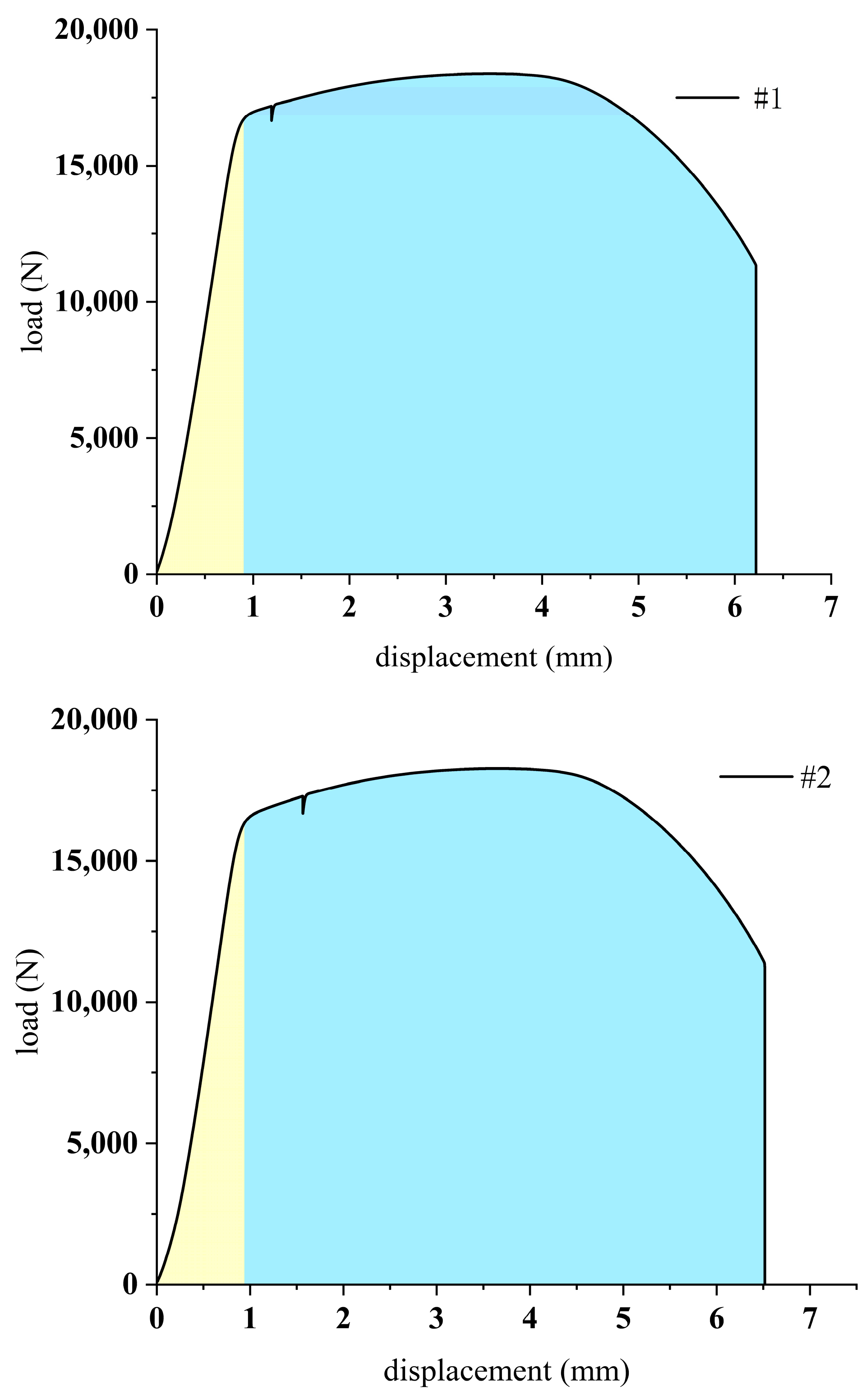
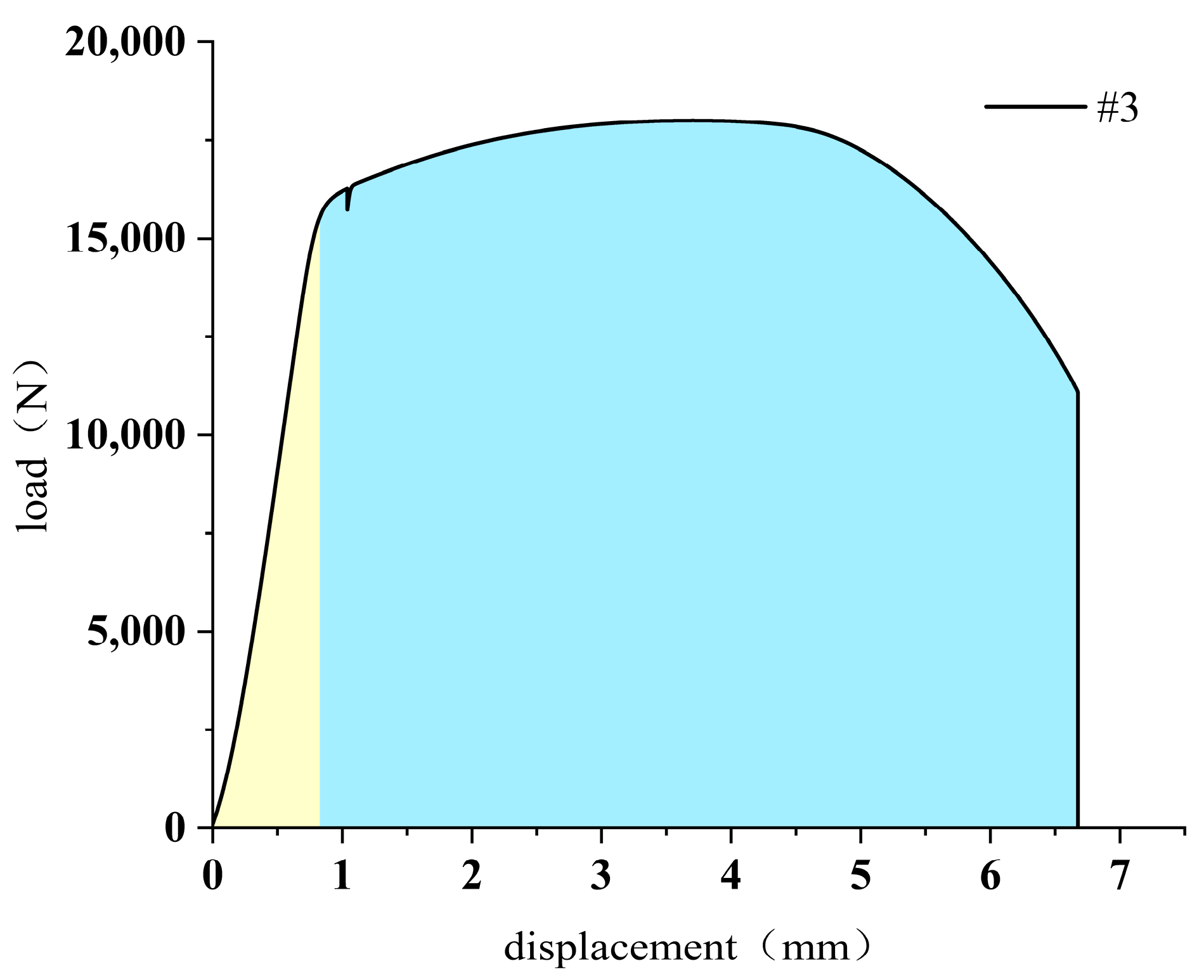
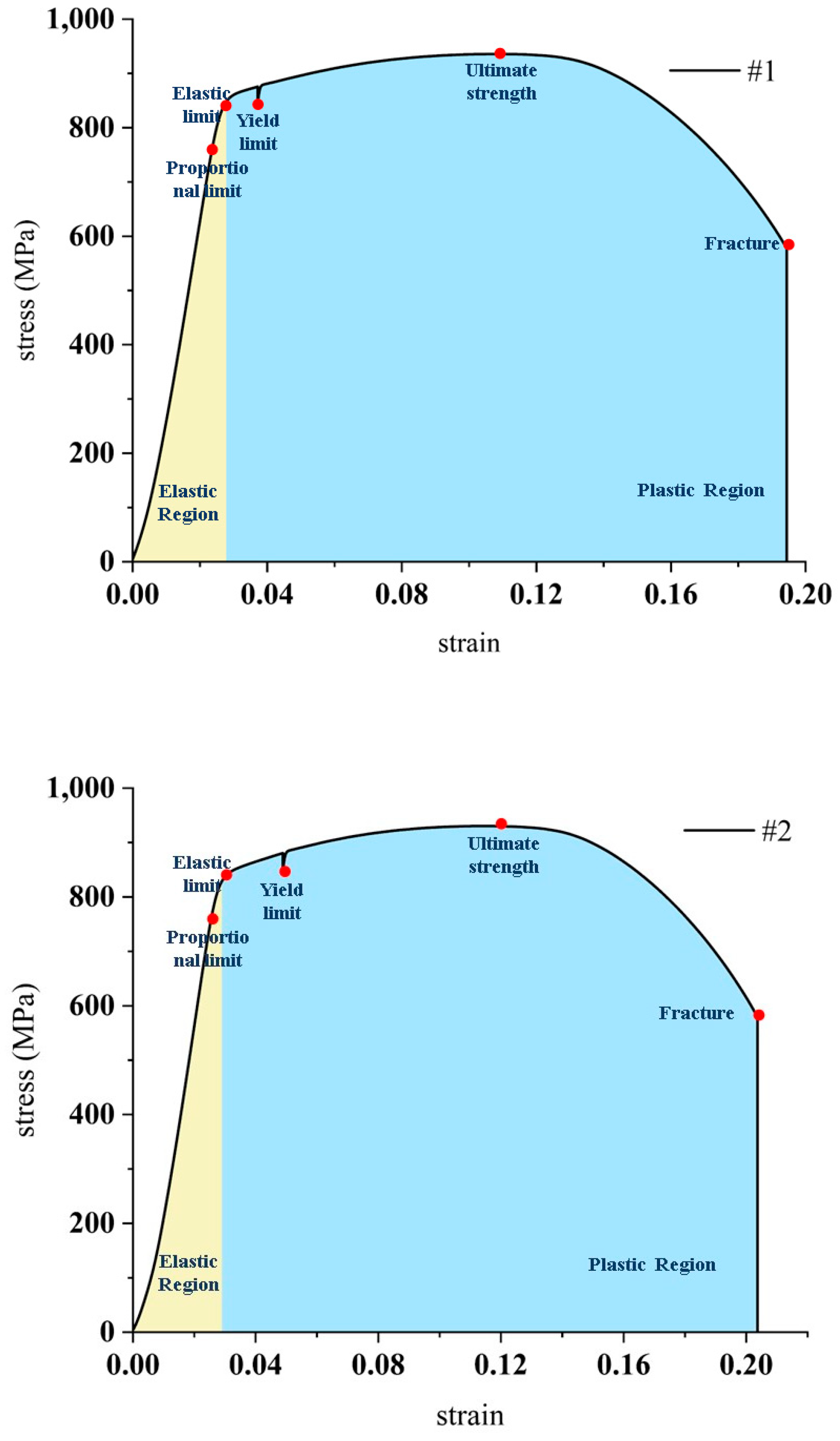
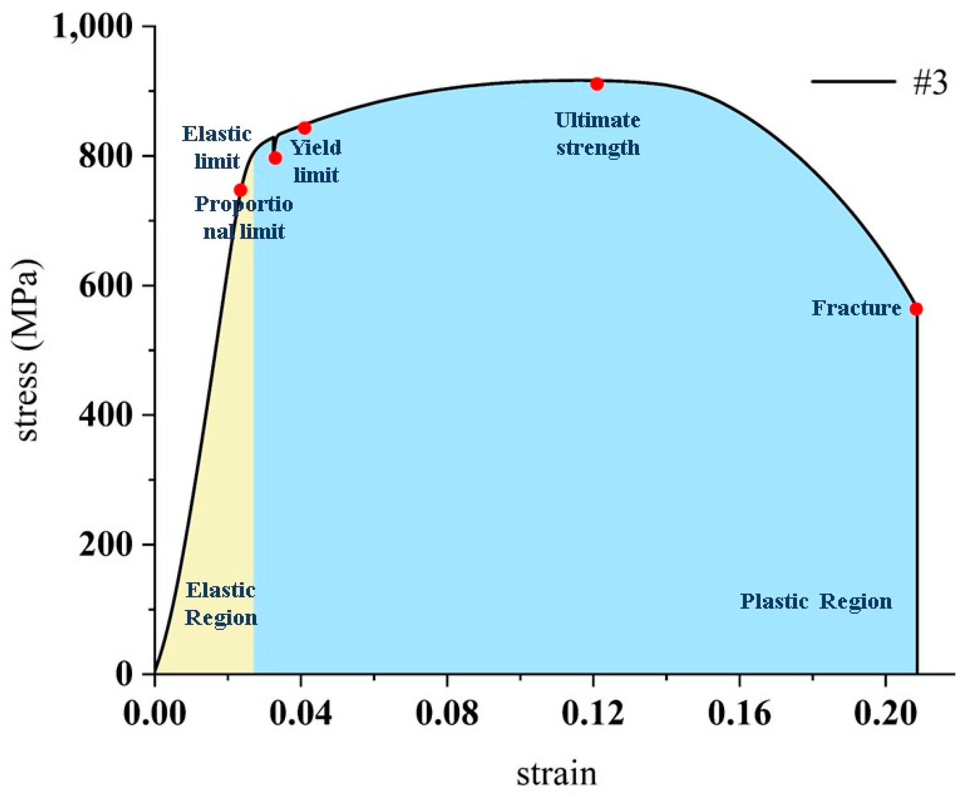
3. Mechanical Properties of 40CrNiMo Alloy Steel for All-Metal Screw Motors

In the selection of materials for the stator and rotor of the all-metal screw motor, 40CrNiM was chosen as the material for the stator after accounting for the extremely high temperature and pressure and very corrosive drilling environment of ultra-deep wells. Furthermore, during the drilling process, the stator and rotor are expanded by heat as the temperature continues rising. To make the stator and rotor undergo the same deformation during the heating process, the rotor material was selected to be the same as that of the stator. To further understand the material mechanical properties of 40CrNiMo, a uniaxial tensile test was conducted on heat-treated 40CrNiMo.
Tensile testing is an important quantitative method to test the physical and mechanical properties of metals and one of the important metal test methods in the field of engineering research. By using a tensile testing machine for metals combined with a displacement measurement sensor, the mechanical index of the metal in the material elastic stage can be obtained accurately. At present, the displacement measurement sensor widely used in tensile testing is the elongator, and the accuracy of the measurement can be greatly improved by choosing a suitable elongator that matches the length of the specimen. For the alloy steel applied to the drilling tools for ultra-deep wells, the tensile and compressive strengths in high-temperature and high-pressure environments are the focus of research. Thus, in this experiment, a high-temperature ceramic axial extensometer was used. This type of extensometer is widely used in metal tensile tests at present. Photographs of the overall arrangement of the extensometer as well as some details are shown in Figure 3.
The mechanical properties of 40CrNiMo high-quality alloy structural steel were obtained according to the indoor test method in the specification “GB228.1-2021 Tensile test of metal materials”. Steel was cut and machined into bar specimens with a diameter D0 of 5 mm and a scale distance L0 of 32 mm. A total of three sets of control tests were designed, named #1, #2 and #3, and the schematic diagram is shown in Figure 4. The tests were conducted on the MTS multifunctional tensile testing machine at the Institute of Water Resources and Hydropower, Sichuan University, using quasi-static, uniform displacement-controlled loading with a loading rate of 0.375 mm/min.
In this study, the modulus of elasticity, yield strength and ultimate strength of the alloy steel material were calculated by combining the tensile values of the testing machine and the deformation measured by the extensometer. Since there were many unstable factors in the initial stage of the actual tensile test, a smooth section of the curve was generally selected for calculations, and the final results are shown in Table 1. From the tensile and deformation data from the tensile process, the load displacement curve and stress–strain curve of the alloy steel were obtained by combining the dimensions of the specimens, as shown in Figure 5 and Figure 6.
From Figure 5 and Figure 6, it can be seen that the load displacement curve and stress–strain of 40CrNiMo are typical corresponding curves of metals after stretching tensile deformation curves with elastic and yielding stages; the yielding stage was longer. By calculation, the final average modulus of elasticity of alloy steel used for all-metal screw motors at room temperature obtained from three sets of test data was 225,765.3 MPa, the yield strength was 825.690 MPa, and the ultimate strength was 927.650 MPa. In comparison with conventional stators made of rubber, which are subject to aging, large deformation and carbonization in high temperature and pressure environments [11,38], it was clear that the alloy steel had more stable mechanical properties and was a good material choice for all-metal screw motors.

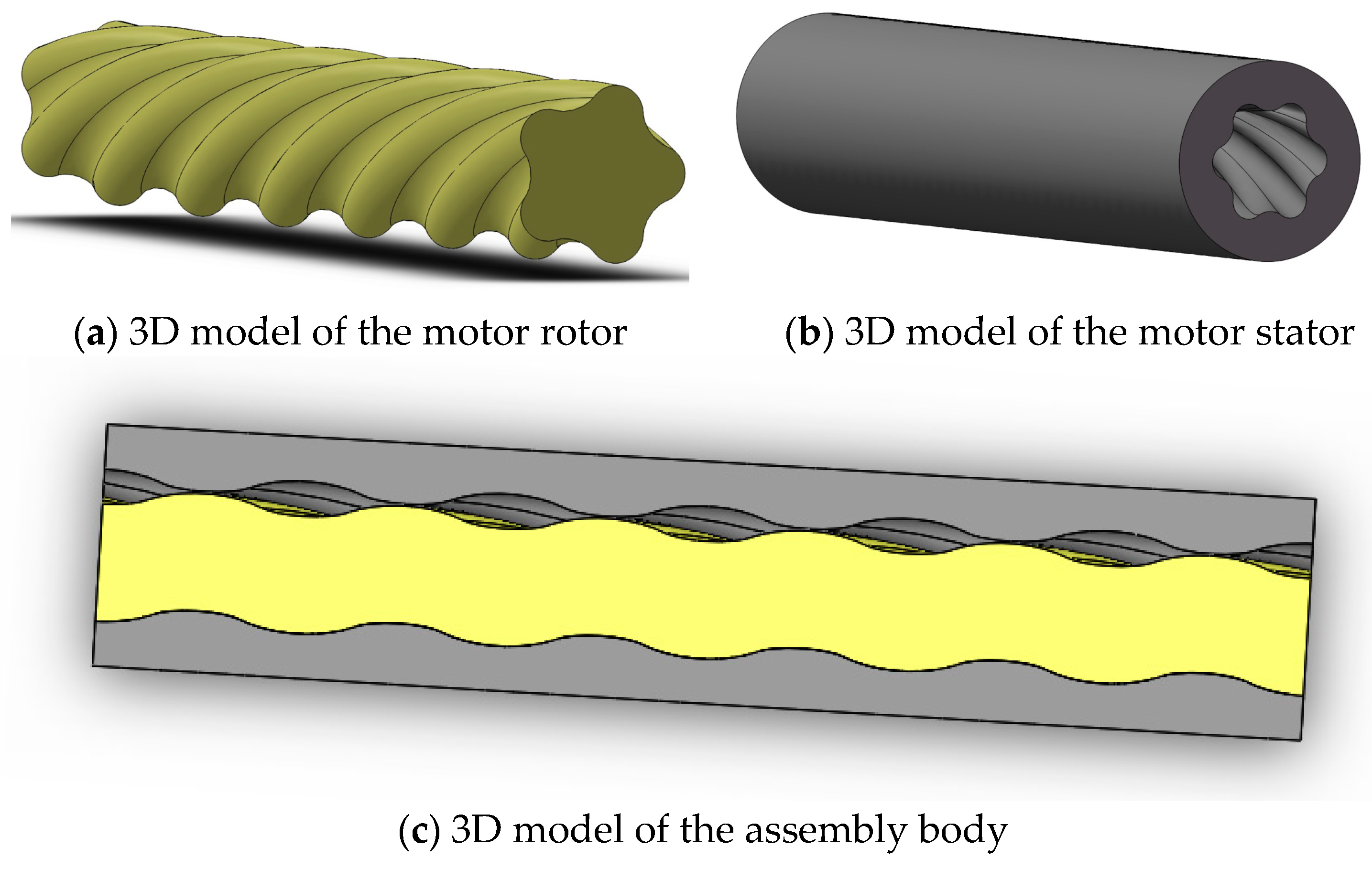
4. All-Metal Screw Rod Motor Modelling

In terms of geometric form, the inner cavity of the all-metal screw motor was a complex threaded tensile surface, and it is difficult for most finite element simulation software modelling functions to create such a complex 3D threaded spatial surface model. Additionally, the all-metal screw motor was designed to lift and discharge drilling fluid through a multi-stage rotary seal with a clearance between the rotor and stator. Therefore, to accurately reflect the interrelationship between the components of the all-metal screw motor, the modelling of the all-metal screw motor in this paper was completed by the professional modelling software SOLIDWORKS. Using the motor stator and rotor end face linearity obtained from the design in Section 2, the head number ratio was taken to be 5:6, the stator lead was 600 mm, the rotor lead was 500 mm, the eccentricity was 4.9 mm, and the stator outer diameter was taken to be 172 mm. The corresponding motor stator, rotor and assembly 3D models were finally obtained, as shown in Figure 7.
The 3D solid file created in SolidWorks was imported into Abaqus software and defined as a solid unit. The material parameters were taken to be a modulus of 225,765.3 MPa and Poisson’s ratio of 0.295 according to the previous section. For the 3D finite element model of an all-metal screw motor, the quality of the initial mesh was of great importance to the accuracy of the solution. In the study, the obtained model was partitioned as well as the grid seed layout, the neutral axis algorithm was used to divide it into a hexahedral swept grid, the grid was encrypted in the stator–rotor contact part, and the final obtained grid model is shown in Figure 8.

5. Deformation Characteristics of the All-Metal Spiral Motor Stator at Different Temperatures and Pressures and Temperature–Pressure Joint Influence

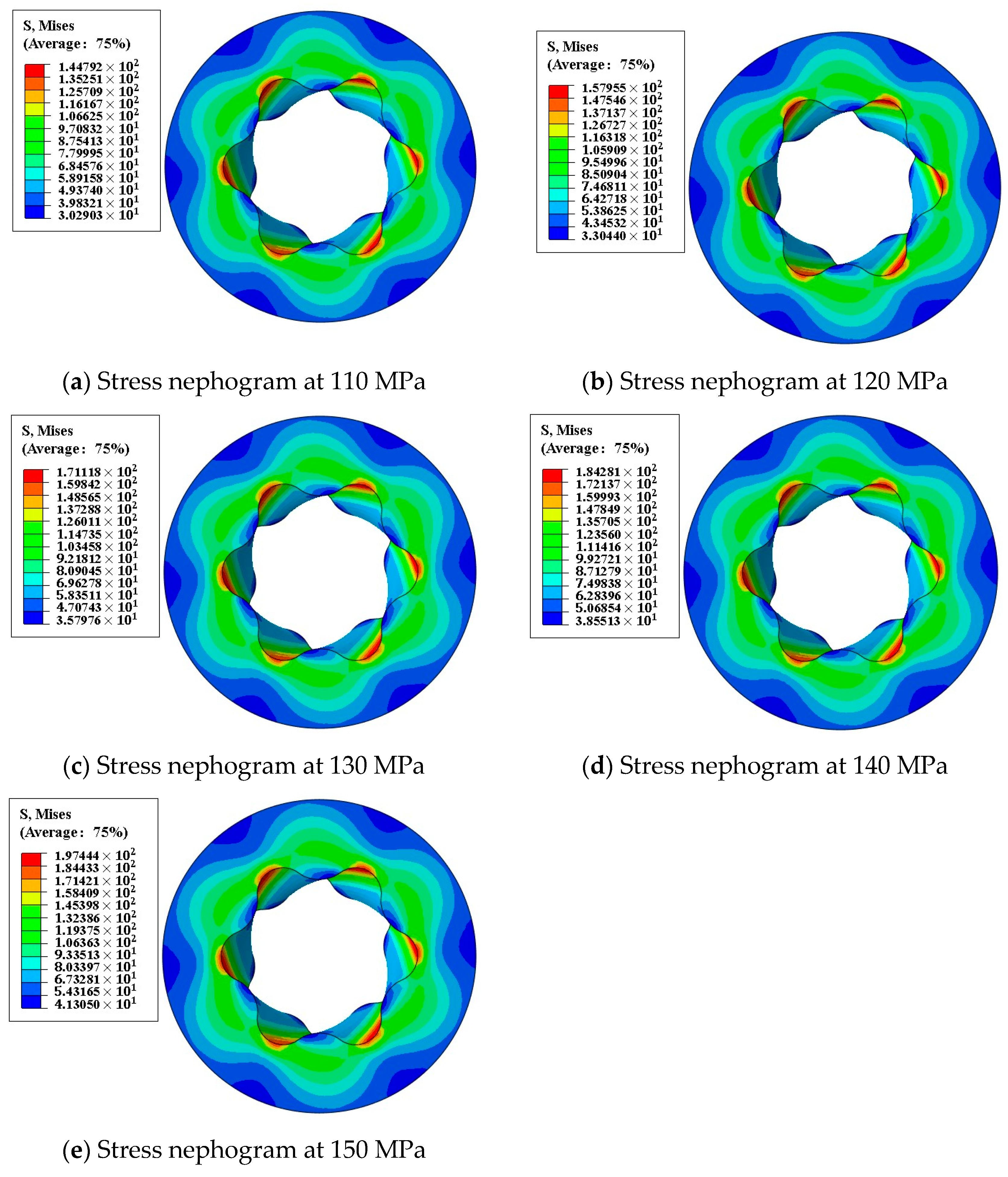
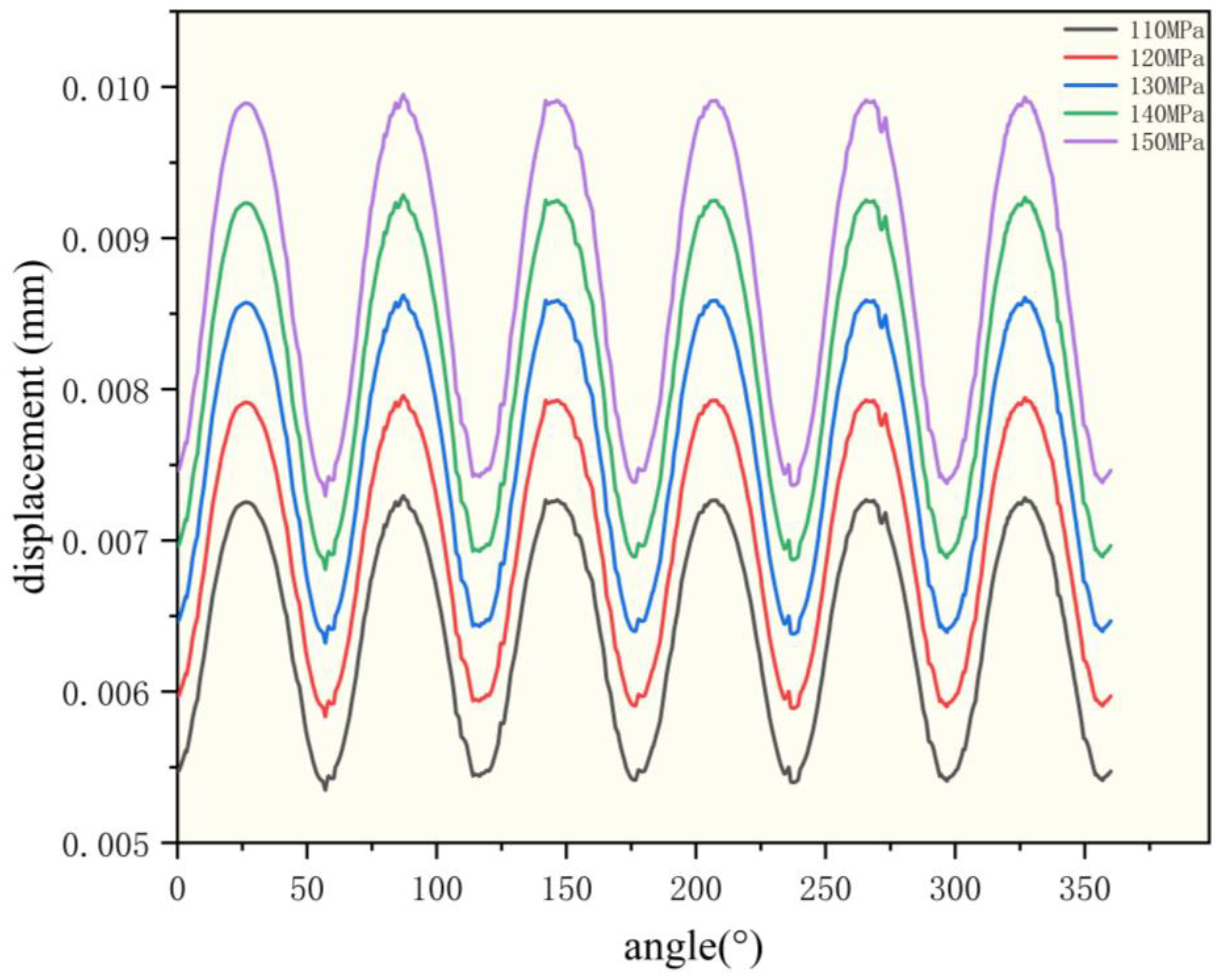
5.1. Influence of Drilling Fluid Pressure

To obtain the deformation of the all-metal screw motor stator under operating conditions, a finite element numerical calculation of its model was performed in this study. Since the displacement of the stator was mainly radial, the overall 1/10th scale was used as the research object for the mesh division as well as the calculation, accounting for the accuracy. Without considering the effect of temperature on the deformation of the all-metal screw motor under actual working conditions, the force condition of the all-metal screw motor, the drilling fluid density was 1.1 g/cm3, g was taken as 9.8 m/s2, and the stator internal pressure was taken as 20 MPa, and the simulations were conducted for ultra-deep well depths of 9000–13,000 m. According to the variation in drilling fluid pressure with depth, uniform loads of 110 MPa, 120 MPa, 130 MPa, 140 MPa and 150 MPa were applied to the inner cavity of the motor stator, and its displacement and stress clouds were obtained by using the finite element software Abaqus, as shown in Figure 9 and Figure 10.
As shown in Figure 9 and Figure 10, the displacement cloud diagrams of the all-metal screw motor stator and the Von Mises stress cloud diagrams under the action of different internal pressures at different burial depths show a certain regular pattern. The diagrams have approximately the same pattern and a more uniform deformation overall, with an approximately circular periodic distribution of both displacement and stress. The maximum displacement of the all-metal screw motor stator convex part was the small diameter of the stator, and the maximum stresses were distributed in the inner diameter depression part of the stator, which is the large diameter of the stator. Under 110 MPa internal pressure, the maximum deformation occurred in the convex part of the stator, which was the part where the stator and rotor were in direct contact, and the displacement reached 0.01073 mm. Compared with the part where the stator and rotor were in direct contact, the displacement in the stator inlet was relatively small, and the maximum value of Mises stress was 144.792 MPa under 110 MPa internal pressure, which was located at the large diameter of the inner concave part of the stator. From 110 MPa to 150 MPa, the corresponding maximum displacement as well as the maximum Mises stress statistics are shown in Table 2. In Table 2, the maximum stator displacement is in the range of 0.010–0.015 mm, and the maximum Mises stress is in the range of 140–200 MPa under different internal pressures.
From Figure 11, with increasing internal pressure, its displacement also increased, but the overall increase was small, at approximately 0.001 mm, which also confirmed the stability of the all-metal screw motor made of 40CrNiMo in a high-pressure environment and showed that the motor was suitable for operation in high-pressure environments deep in the ground.
To better describe the deformation of the inner wall of the stator, a right-angle coordinate system was established in the model with the center of the circle as the midpoint, and a circular path was defined by using the define path function of Abaqus; 2000 points were taken on this path. Afterwards, the displacement magnitude on this path was obtained, and the radial displacement curves corresponding to different angles of the circumference were obtained by converting the circumference into angles, as shown in Figure 12. This curve shows that the stator displacement curve of the all-metal screw motor was undulating but flat and smooth, with the smallest displacement at the depression and the largest displacement at the bulge, showing a certain periodicity. The stator inner diameter decreased from a small diameter to a large diameter and then increased to a small diameter, which was very consistent with the stator configuration. It is also obvious from Figure 12 that with increasing internal pressure, the displacement also increased, and the periodic regularity type of this displacement distribution was the same for different internal pressures.

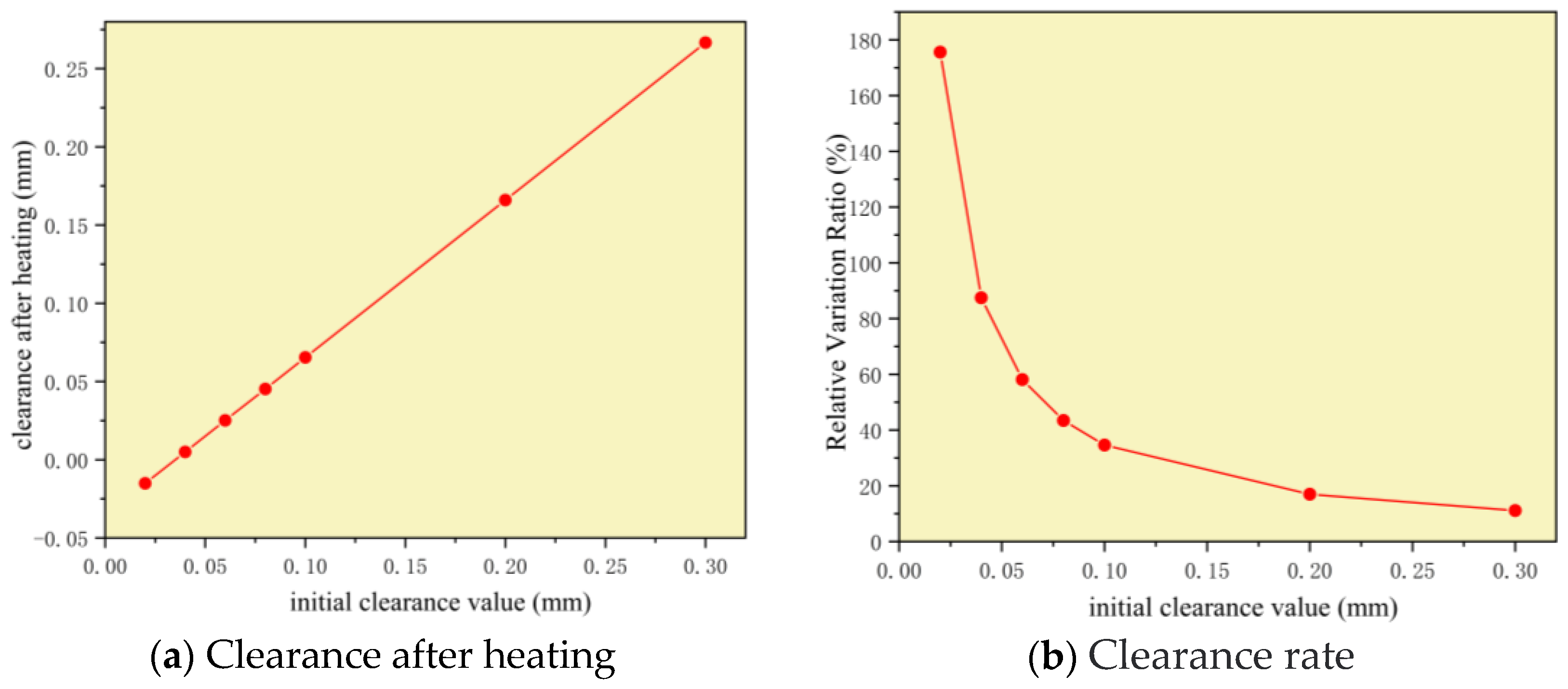
5.2. Effect of a High-Temperature Environment on All-Metal Screw Motor Clearance

All-metal screw motors used in ultra-deep and extra-deep wells are subject to expansion and deformation of metallic materials due to the complex deep-ground environment and the high-temperature extremes they are subjected to, which can significantly affect the clearance fit of the stator and rotor. Therefore, the study of the clearance variation in all-metal screw motors in deep-ground high-temperature environments is of great significance for designing motor clearance values to cope with drilling environments at different depths.
In this study, the initial temperature of the stator was assumed to be the ground ambient temperature of 20 °C. When the temperature rose uniformly to a certain value, a certain deformation and corresponding thermal stress were generated inside the stator. In particular, the following assumptions were made in the finite element analysis of the deformation of the metal motor stator as well as the rotor under the action of the temperature field: (1) The ambient temperature did not affect the material parameters and thermodynamic parameters of the metal. (2) There was no temperature gradient in the motor stator in the axial direction. (3) The temperature increased by 3 °C for every 100 m increase in depth. As above, well depths of 9000–13,000 m were simulated, and thus, the corresponding ambient temperatures were 290 °C, 320 °C, 350 °C, 380 °C and 410 °C.
Material parameters from Section 2 and the standard were combined, that is, density ρ = 7.19, modulus of elasticity according to test results taken at room temperature was 225,765.3 MPa, with Poisson’s ratio of 0.295, thermal conductivity of 0.937, specific heat capacity of 0.461 J / ( g . ° C ) , and volume thermal expansion coefficient of 6.2 × 10 6 .
To investigate the effect of temperature on the clearance of all-metal screws, thermal loads were applied separately to stator and rotor models fitted with different original clearance values without considering the internal pressure. According to the 410 °C thermal load applied to seven different sizes of stator and one size of rotor, corresponding stator and rotor deformation and stress clouds were obtained, as shown in Figure 13.
The deformation of the metal stator and rotor of the screw motor under the action of an ambient temperature of 410 °C and the change in the clearance are shown in Table 3.
From Figure 13 and Figure 14, it can be seen that (1) the deformation of the all-metal screw motor under the action of ambient temperature was somewhat larger compared to the deformation under the action of internal pressure, and the all-metal screw motor expanded outward on both the inner and outer surfaces of its metal stator and rotor with a displacement of close to 0.2 mm under the heat load of 410 °C. (2) For the metal stator–rotor clearance model of 0.02 mm, the fit clearance reached −0.01512 mm, and the relative change rate of the clearance reached 175.58%, the stator–rotor overfilling state due to expansion. (3) The rate of change in the fit clearance decreased with increasing initial clearance of the stator–rotor, and when the clearance increased to 0.1 mm, the relative rate of change rate in the clearance was 34.607%, and when the initial clearance was 0.2 mm, the relative rate of change was only 16.9%, i.e., basically no change. (4) As the ambient temperature field continued to increase, the clearance value after expansion continued to increase, but the relative rate of change rate in clearance continued to decrease, and after the initial clearance value of 0.2 mm, the rate of change in clearance started leveling off.
Therefore, to ensure that the stator and rotor of the all-metal screw motor could maintain the engagement operation under the high-temperature environment of the extra-deep well, it was determined that the minimum fit clearance of the stator and rotor of the all-metal screw motor should be greater than 0.2 mm.

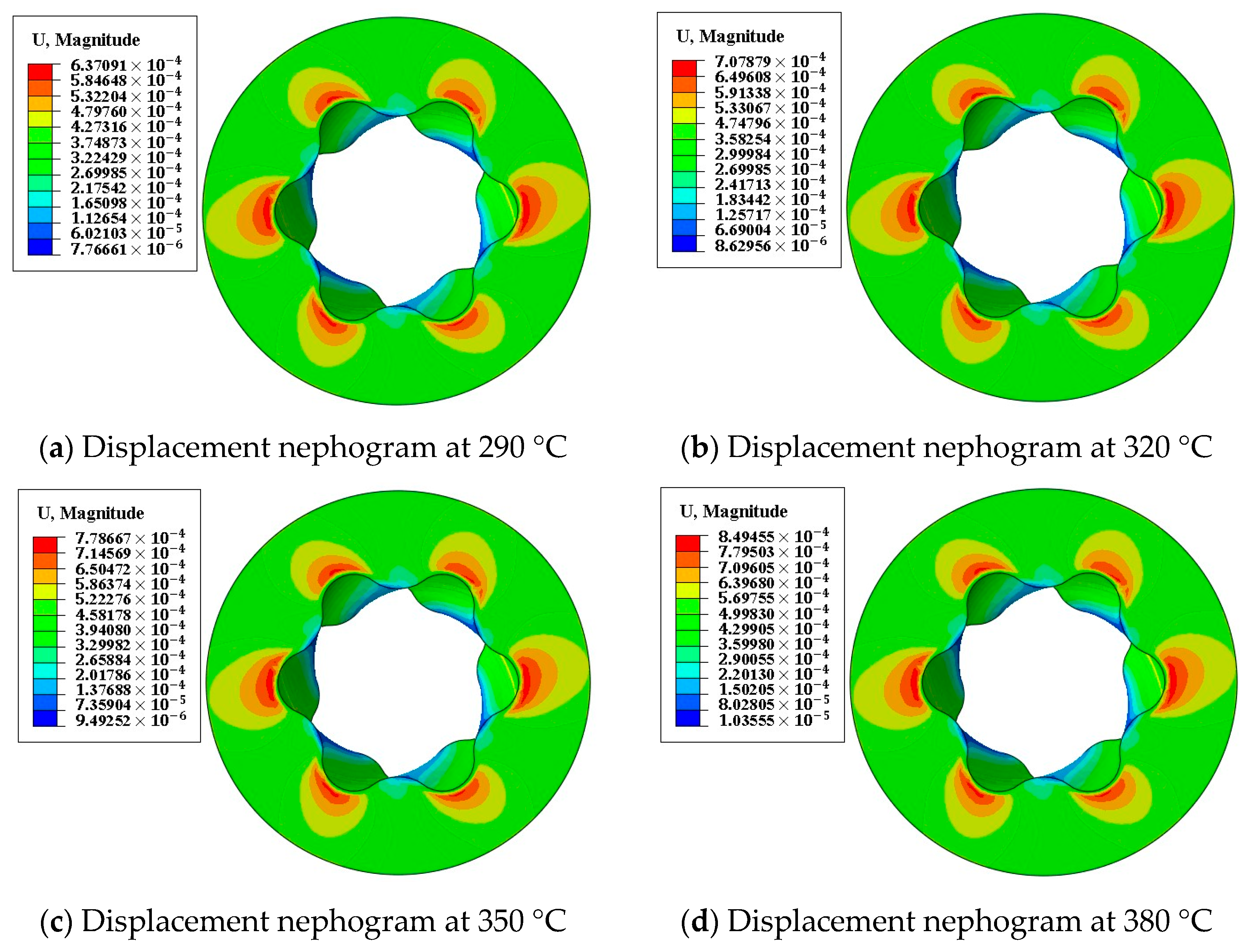
5.3. Analysis of Motor Stator Deformation under the Fluid Disturbance Effect

To better study the temperature field effect caused by fluid disturbance in the all-metal screw motor, the deformation of the screw motor stator was analyzed under fluid heat exchange conditions; the inner chamber of the stator with the surface heat transfer coefficient of the transported oil was 20 W/(m2 °C), the initial ambient temperature was taken as 20 °C, and the deformation at the heat flow temperature of 290–410 °C is shown in the following figure:
It is clear from Figure 15 that the maximum displacement of the all-metal screw motor stator was positively correlated with the ambient temperature of the inner cavity under the effect of the temperature field caused by fluid disturbance. Additionally, the displacement caused by the heat of fluid disturbance was negligible compared to the effect of clearance due to downhole ambient temperature on the amount of clearance under the initial installation of the screw motor. Therefore, the effect of temperature was only considered in this study for the variation in the stator–rotor clearance value of the all-metal screw motor under the effect of a high ambient temperature downhole.

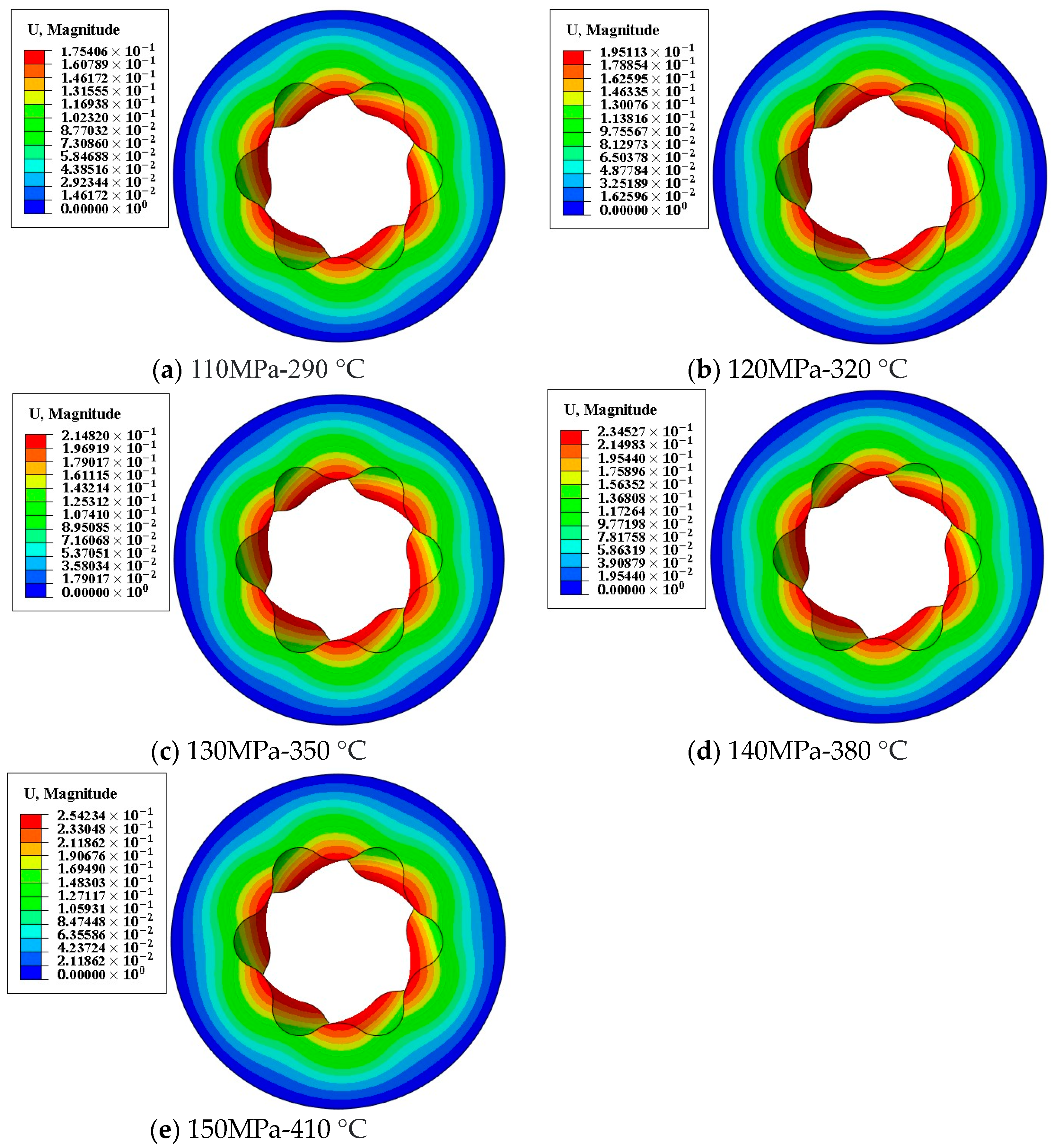
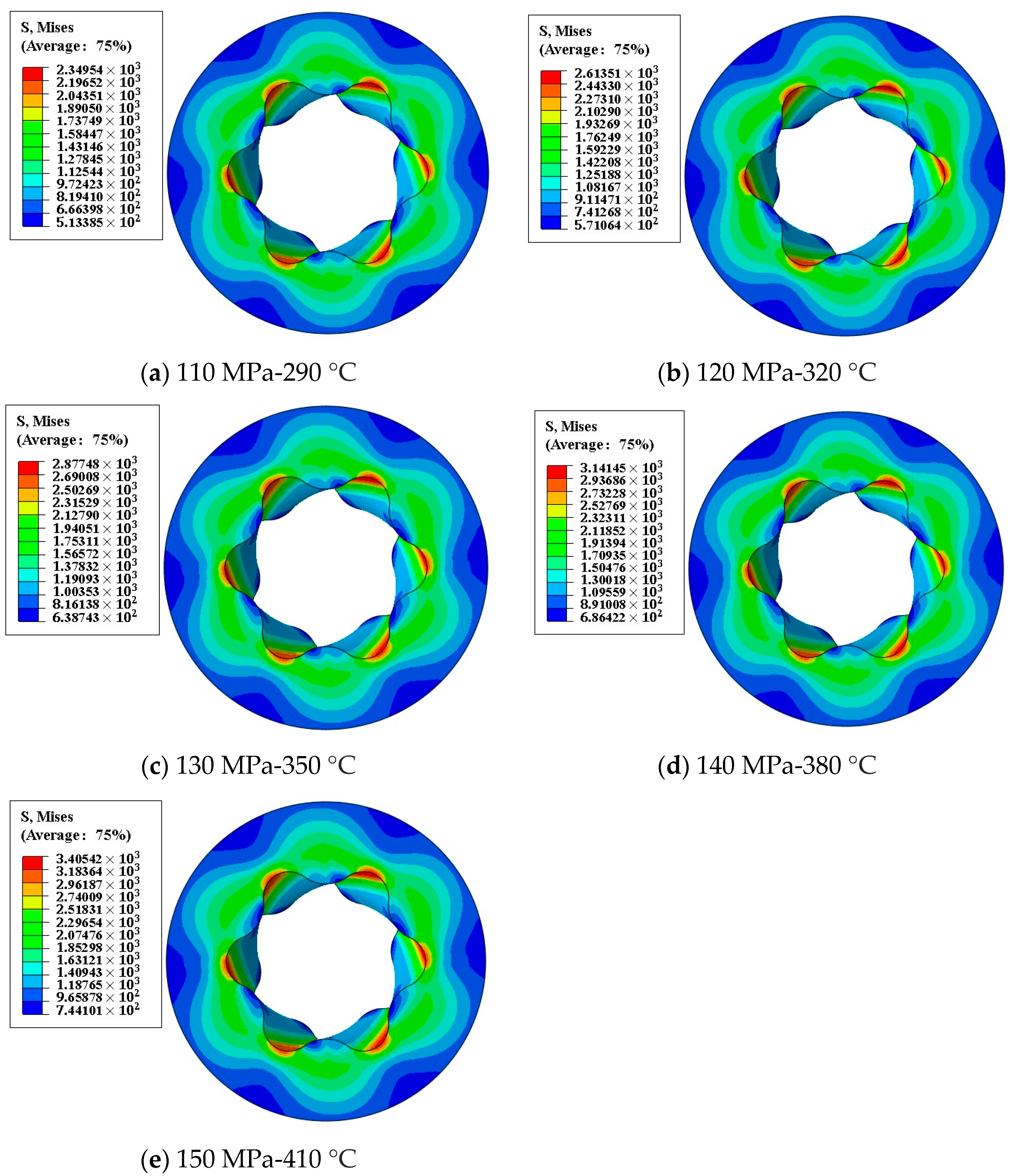
5.4. Deformation Characteristics of Spiral Motor Stator under the Joint Influence of Temperature and Pressure

In the previous section, the deformation of the stator of an all-metal screw motor was studied in a high-pressure environment and in a high-temperature environment. However, under actual working conditions, the joint influence of temperature–pressure conditions on the deformation of the metal stator and rotor should be taken into full consideration.
Therefore, the analysis of the deformation of the stator of the all-metal screw motor under the joint influence of temperature and pressure is of great significance to guide the selection of the fit clearance and the design of the configuration parameters of the all-metal screw motor.
To more truly reflect the extreme environment of high temperature and pressure during the drilling of ultra deep wells, the effects from the joint influence of temperature and pressure were studied for all-metal screw motors. The temperature and pressure settings and parameter settings were the same as above. Considering the actual working conditions and the simplicity of the calculation, the outer wall of the stator was completely constrained, and the two end faces were symmetrically constrained. The obtained cloud diagrams of displacement and stress are shown in Figure 15 and Figure 16, and the maximum displacement of the stator obtained by statistics is shown in Table 4.
The results of the calculation in Figure 16 and Figure 17 show that after temperature–pressure joint influence, the regularity of the distributions of displacement and stress were similar. Due to the specific form of the stator structure, the displacement and stress distribution were circularly periodic. Comparing Table 2, Table 4, and Figure 18 shows that with the addition of the joint effect of temperature, the displacement of the stator changed by a greater amount after joint influence compared to the direct effect of internal pressure. Moreover, as the drilling depth continued to increase, the amount of stator displacement increase caused by the joint influence also continued to increase. It is evident that the temperature would have a great influence on all-metal screw motor drilling tools in deep underground environments of ultra-deep wells, and special attention should be focused on the influence of the temperature of deep underground environments on the performance of the all-metal screw motor.

6. Conclusions

In this paper, a three-dimensional finite element model of an all-metal screw motor applicable to the extremely high-temperature and high-pressure drilling environment of an ultra-deep well was established, and the structural design and working principle of the all-metal screw motor were clarified. The mechanism of the effects of temperature as well as pressure on the deformation of the all-metal screw motor was studied by way of finite element numerical calculations, and the variation in clearance values of the all-metal screw motor under the action of ambient temperature was investigated, with the following conclusions:
(1)
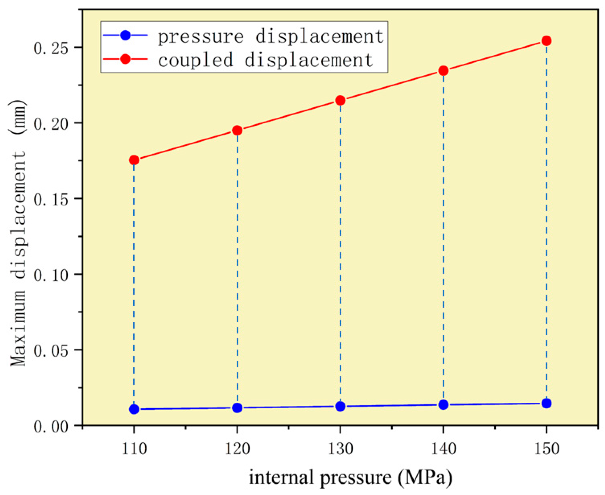
Under the action of the internal pressure of the drilling fluid, the overall deformation of the all-metal screw motor was relatively uniform, and both displacement and stress were distributed periodically along the circumference, where the largest displacement was located in the convex part of the motor stator, that is, the small diameter of the stator, with a maximum displacement of 0.01073 mm under 110 MPa internal pressure. The maximum stress was distributed at the depression of the inner diameter of the stator. At the large diameter of the stator, the Mises stress reached 144.792 MPa under the action of 110 MPa internal pressure.
(2)
The deformation of the all-metal screw motor was greater under ambient temperature than under internal pressure. For the metal stator–rotor clearance model of 0.02 mm, the fit clearance reached −0.01512 mm, and the relative rate of change in the clearance reached 175.58% when the stator–rotor was overfilled due to expansion. As the initial clearance value continued to increase, the relative rate of change in the clearance after its expansion decreased. When the initial clearance was 0.1 mm, the relative rate of change was 34.607%, and when the initial clearance was 0.2 mm, the relative rate of change was only 16.9%, at which point the relative rate of change curve leveled off and there was basically no change. Therefore, to ensure that the stator and rotor of the all-metal screw motor can maintain engagement operation in high-temperature environments of ultra-deep wells, the minimum fit clearance of the stator and rotor of the all-metal screw motor should be greater than 0.2 mm.
(3)
Considering the all-metal screw motor stator deformation caused by the nonuniform temperature field under the effect of fluid disturbance, the maximum stator displacement was positively correlated with the ambient temperature of the inner cavity. Additionally, the displacement caused by the heat of fluid disturbance was very small compared to the effect of the downhole ambient temperature on the amount of clearance for the initial installation of the screw motor.
(4)
The deformation of the stator of the all-metal screw motor under the effect of temperature–pressure joint influence was greater than that under the effect of internal pressure alone. Under the environment of 110 MPa and 290 °C, the deformation of the all-metal screw motor stator reached 0.175406 mm, which was much larger compared to the displacement of 0.01073 under 110 MPa internal pressure alone. Temperature clearly has a greater impact than pressure on all-metal screw motors. As the drilling depth continued to increase, the amount of increase in stator displacement caused by the joint influence also continued to increase. Therefore, special attention should be given to the effect of ambient temperature on the performance of all-metal screw motors deep underground. Overall, the metal screw motor designed in this study is expected to have good performance and stability with minimal deformation in the high-temperature and high-pressure environment of 10,000 m ultra-deep wells.

Author Contributions

Conceptualization, X.F. and C.Z.; Methodology, X.F. and C.Z.; Software, X.F.; Validation, X.Y.; Formal analysis, L.C.; Investigation, C.L.; Resources, L.C.; Data curation, J.L.; Writing—original draft, X.F.; Writing—review & editing, X.F.; Supervision, H.X.; Project administration, C.Z.; Funding acquisition, C.L. All authors have read and agreed to the published version of the manuscript.

Funding

This research was founded by the National Key R&D Program of China, grant number 2022YFB3706605, Sichuan Science and Technology Program (2023NSFSC0919), the R&D Program of Sichuan University (2023SCU12122) and the National Natural Science Foundation of China (No. 51827901).

Institutional Review Board Statement

Not applicable.

Informed Consent Statement

Not applicable.

Data Availability Statement

The data used to support the findings of this study cannot be shared.

Conflicts of Interest

The authors declare that they have no competing financial interest or personal relationships that could appear to have influenced the work reported in this paper.

References

  1. Xie, H.; Lu, J.; Li, C.; Li, M.; Gao, M. Experimental study on the mechanical and failure behaviors of deep rock subjected to true triaxial stress: A review. Int. J. Min. Sci. Technol. 2022, 32, 915–950. [Google Scholar] [CrossRef]
  2. Xie, H.P.; Gao, F.; Ju, Y. Research and development of rock mechanics in deep grounp engineering. Chin. J. Rock. Mech. Eng. 2015, 18, 2161–2178. [Google Scholar] [CrossRef]
  3. Li, C.; Caner, F.C.; Chau, V.T.; Bažant, Z.P. Spherocylindrical microplane constitutive model for shale and other anisotropic rocks. J. Mech. Phys. Solids 2017, 103, 155–178. [Google Scholar] [CrossRef] [Green Version]
  4. Xie, Y.; Hou, M.Z.; Li, C. Anisotropic characteristics of acoustic emission and the corresponding multifractal spectrum during progressive failure of shale under cyclic loading. Int. J. Rock Mech. Min. Sci. 2023, 165, 105364. [Google Scholar] [CrossRef]
  5. Guo, D.; Xie, H.-P.; Chen, L.; Zhou, Z.-Y.; Lu, H.-P.; Dai, L.; Wang, D.-M.; Wang, T.-Y.; Li, J.; He, Z.-Q. In-situ pressure-preserved coring for deep exploration: Insight into the rotation behavior of the valve cover of a pressure controller. Pet. Sci. 2023. [Google Scholar] [CrossRef]
  6. Guo, D.; Li, J.; Wang, D.; Zhang, Y.; Fang, X.; Xie, H. Structural Improvement of Differential Motion Assembly in In Situ Pressure-Preserved Coring System Using CFD Simulation. Appl. Sci. 2023, 13, 4108. [Google Scholar] [CrossRef]
  7. Zou, C.; Wang, C.; Peng, C.; Wu, C.; Gao, Y. Some thoughts and suggestions on the development of scientific deep drilling in mainland China. Mod. Geol. 2023, 37, 1–14. [Google Scholar] [CrossRef]
  8. Changshuai, S.; Yike, C.; Xiaohua, Z. Applicability evaluation and hysteresis heat effect of rubber constitutive model of PDM stator bushing at high temperature in deep well. Arab. J. Sci. Eng. 2019, 44, 6057–6066. [Google Scholar] [CrossRef]
  9. Chen, J.; Wang, F.; Shi, G.; Cao, G.; He, Y.; Ge, W.; Liu, H.; Wu, H. Finite element analysis for adhesive failure of progressive cavity pump with stator of even thickness. J. Pet. Sci. Eng. 2015, 125, 146–153. [Google Scholar] [CrossRef]
  10. Delpassand, M.S. Stator life of a positive displacement downhole drilling motor. J. Energy Resour. Technol. 1999, 121, 110–116. [Google Scholar] [CrossRef]
  11. Han, C.; Zhang, J.; Liang, Z. Thermal failure of rubber bushing of a positive displacement motor: A study based on thermo-mechanical coupling. Appl. Therm. Eng. 2014, 67, 489–493. [Google Scholar] [CrossRef]
  12. Shi, C.; Zhu, X.; Chen, Y.; Tang, L. Failure analysis of general stator and uniform wall thickness stator. Eng. Fail. Anal. 2018, 94, 239–248. [Google Scholar] [CrossRef]
  13. Nguyen, T.C.; Al-Safran, E.; Nguyen, V. Theoretical modeling of positive displacement motors performance. J. Pet. Sci. Eng. 2018, 166, 188–197. [Google Scholar] [CrossRef]
  14. Fan, P.; Kuang, Y. A novel line type optimization and theoretical equilibrium method analysis for common hypocycloid screw motor. Ind. Lubr. Tribol. 2021, 73, 911–921. [Google Scholar] [CrossRef]
  15. Xin, C.; Qi, C. The research and implementation for the conjugate vice type line of stator and rotor of single screw motor. In Proceedings of the 2nd International Conference on Electronic & Mechanical Engineering and Information Technology, Shenyang, China, 7 September 2012; pp. 1279–1282. [Google Scholar]
  16. Zhang, S.; Gu, Z.; Zhang, Z. Dynamic balancing method for the single-threaded, fixed-pitch screw rotor. Vacuum 2013, 90, 44–49. [Google Scholar] [CrossRef]
  17. Zhang, J.; Han, C.; Liang, Z. Physics of failure analysis of power section assembly for positive displacement motor. J. Loss Prev. Process Ind. 2016, 44, 414–423. [Google Scholar] [CrossRef]
  18. Alvarez, A.A.; Boscan, J. Predicting rotor-stator fit in positive displacement motors PDMs. In Proceedings of the SPE/IADC Drilling Conference and Exhibition, The Hague, The Netherlands, 14–16 March 2017. [Google Scholar]
  19. Shi, C.; Wan, X.; Zhu, X.; Chen, K. A study on mechanical properties of equal wall thickness rubber bushing of positive displacement motor based on hydrogenated nitrile butadiene rubber aging test. Petroleum 2022, 8, 403–413. [Google Scholar] [CrossRef]
  20. Wang, H.; Wang, S.; Lv, X. The effects of temperature on the mechanical and tribological properties of progressing cavity pump NBR stator rubber. Mechanics 2016, 22, 308–312. [Google Scholar] [CrossRef] [Green Version]
  21. Wang, K.; Chen, L.; Sun, X. FEA of Stator of the Equal Wall Thickness of the Multi-thread Screw Drilling Tool. In Proceedings of the 2010 International Conference on Measuring Technology and Mechatronics Automation, Changsha, China, 13–14 March 2010; pp. 249–252. [Google Scholar]
  22. Zhu, X.; Ji, W. Finite element analysis and experimental study on roll-forming method in iso-wall thickness stator bushing of screw drilling. Int. J. Adv. Manuf. Technol. 2017, 93, 1939–1952. [Google Scholar] [CrossRef]
  23. Polmanteer, K.E. Silicone rubber, its development and technological progress. Rubber Chem. Technol. 1988, 61, 470–502. [Google Scholar] [CrossRef]
  24. Liu, S. Development of 7LZ172 Metal Screw Motor. Master’s Thesis, Xi’an Shiyou University, Xi’an, China, 2016. [Google Scholar]
  25. Wang, H.M.; Lv, X.R.; Wang, S.J. The swelling properties of nitrile rubber with different acrylonitrile contents in cyclohexane medium research. Adv. Mater. Res. 2014, 936, 1942–1947. [Google Scholar] [CrossRef]
  26. Shi, C.; Chen, K.; Zhu, X.; Tang, L. Thermal failure of 2/3 PCP in high temperature environment and optimization analysis of stator and rotor meshing parameters. J. Loss Prev. Process Ind. 2019, 61, 174–182. [Google Scholar] [CrossRef]
  27. Lu, J.; Wang, Y.; Kong, L.; Li, J. Analysis of output performance of all-metal progressive cavity motor. Geoenergy Sci. Eng. 2023, 222, 211456. [Google Scholar] [CrossRef]
  28. Chatterjee, K.; Dick, A.; Grimmer, H.; Herlitzius, J.; Otto, M.; Klotzer, S.; Epplin, D.; Schroder, J.; Macpherson, J. High Temperature 300 °C Directional Drilling System, including Drill Bit, Steerable Motor, and Drilling Fluid. In Proceedings of the Geothermal Resource Council Conference, Portland, OR, USA, 28 September–1 October 2014. [Google Scholar]
  29. Chatterjee, K.; Aaron, D.; Macpherson, J. High Temperature 300 °C Directional Drilling System; Baker Hughes Oilfield Operations: Houston, TX, USA, 2015. [Google Scholar]
  30. Chatterjee, K.; Macpherson, J.; Dick, A.; Grimmer, H.; Klotzer, S.; Schroder, J.; Epplin, D.; Hohl, C.; Gacek, S. Development of a directional drilling system for operation at 300 °C for geothermal applications. In Proceedings of the Geothermal Resource Council Conference, Sacramento, CA, USA, 23–26 October 2016. [Google Scholar]
  31. Stefánsson, A.; Duerholt, R.; Schroder, J.; Macpherson, J.; Hohl, C.; Kruspe, T.; Eriksen, T.-J. A 300 degree celsius directional drilling system. In Proceedings of the IADC/SPE Drilling Conference and Exhibition, Fort Worth, TX, USA, 6–8 March 2018. [Google Scholar]
  32. Liu, L.; Wang, Y.; Wang, Z.; Lu, J.; Zhang, K.; Liu, B. Research status and key technologies of all-metal screw drill. Prospect. Eng. (Geotech. Drill. Eng.) 2020, 47, 24–30. [Google Scholar] [CrossRef]
  33. Zhu, X.; Li, J.; Shi, C. A Combination Type All-Metal Screw Stator. CN202260661U, 30 May 2012. [Google Scholar]
  34. Zhong, L.; Kuang, Y.; Shu, F.; Zhang, C. Interference design method of screw motor considering influence of pressure and temperature. J. Eng. Des. 2021, 28, 321–328. [Google Scholar] [CrossRef]
  35. Olivet, A.; Gamboa, J.; Kenyery, F. Experimental study of two-phase pumping in a progressive cavity pump metal to metal. In Proceedings of the SPE Annual Technical Conference and Exhibition, San Antonio, TX, USA, 29 September–2 October 2002; p. SPE–77730–MS. [Google Scholar]
  36. Lu, Y. Linear Analysis of Screw Motor Rotor. Master’s Thesis, Xi’an Shiyou University, Xi’an, China, 2010. [Google Scholar]
  37. Yu, L. Replacement and correction of screw drill motor lines. Pet. Mach. 2004, 32, 12–14. [Google Scholar]
  38. Om, I.L.; Han, U.C.; Ryo, S.I.; Kim, C.Y.; Sol, Y.N. A New Analytical Approach To Calculate a Slippage inside a Progressing Cavity Pump with a Metallic Stator Using a Middle Streamline and a Structural Periodicity. SPE J. 2022, 27, 552–565. [Google Scholar] [CrossRef]
Figure 1. Clearance fit of an all-metal screw motor.
Applsci 13 08630 g001
Figure 2. Bone line and equidistant line of rotor and stator.
Applsci 13 08630 g002
Figure 3. Arrangement of the extensometer.
Applsci 13 08630 g003
Figure 4. Schematic diagram of metal stretching of #1, #2 and #3 metal specimens.
Applsci 13 08630 g004
Figure 5. Load displacement curve of #1, #2 and #3 metal specimens.
Applsci 13 08630 g005aApplsci 13 08630 g005b
Figure 6. Stress–strain curve and special stress points of #1, #2 and #3 metal specimens.
Applsci 13 08630 g006aApplsci 13 08630 g006b
Figure 7. Models of the all-metal screw motor stator and rotor.
Applsci 13 08630 g007
Figure 8. Meshing.
Figure 8. Meshing.
Applsci 13 08630 g008
Figure 9. Displacement cloud diagrams of motor stator at 110–150 MPa.
Applsci 13 08630 g009
Figure 10. Stress cloud diagrams of motor stator at 110–150 MPa.
Applsci 13 08630 g010
Figure 11. Influence of internal pressure on maximum stator displacement.
Applsci 13 08630 g011
Figure 12. Variation in the displacement of the metal stator for one week with different internal pressures.
Applsci 13 08630 g012
Figure 13. Thermal expansion displacement nephograms of the stator and rotor.
Applsci 13 08630 g013
Figure 14. Change in clearance after heating.
Applsci 13 08630 g014
Figure 15. Thermal displacement consideration of the fluid disturbance effect.
Applsci 13 08630 g015
Figure 16. Displacement under temperature–pressure joint influence.
Applsci 13 08630 g016
Figure 17. Stress under temperature–pressure joint influence.
Applsci 13 08630 g017
Figure 18. Analysis of change in stator displacement after joint influence.
Applsci 13 08630 g018
Table 1. Metal tensile test data.
Specimen NumberModulus of Elasticity
(MPa)
Yield Strength (MPa)Ultimate Strength
(MPa)
#1225,676845.792935.859
#2221,745830.591930.383
#3229,875800.692916.717
Average225,765.3825.690927.650
Table 2. Displacement and stress variation of the all-metal screw motor without pressure.
Pressure (MPa)Maximum Displacement (MPa)Maximum Mises Stress (MPa)
1100.01073144.792
1200.01171157.955
1300.01268171.118
1400.01366184.281
1500.01464197.444
Table 3. Variation of all-metal screw motor clearance under thermal load.
Clearance (mm)Minimum Variation of Stator Inner Surface
(mm)
Maximum Variation of Rotor Surface
(mm)
Clearance
after Heating
(mm)
Relative Variation Ratio of Clearance (%)
0.020.1896440.22476−0.01512175.58
0.040.1897730.224760.00501387.4675
0.060.1899030.224760.02514358.095
0.080.1900280.224760.04526843.415
0.10.1901530.224760.06539334.607
0.20.1907760.224760.16601616.992
0.30.1914340.224760.26667411.10867
Table 4. Variation in the maximum displacement and stress under temperature–pressure joint influence.
Pressure
(MPa)
Temperature (°C)Maximum Displacement (mm)Maximum Stress (MPa)
1102900.1754062349.54
1203200.1951132613.51
1303500.2148202877.48
1403800.2345273141.54
1504100.2542343405.42
Disclaimer/Publisher’s Note: The statements, opinions and data contained in all publications are solely those of the individual author(s) and contributor(s) and not of MDPI and/or the editor(s). MDPI and/or the editor(s) disclaim responsibility for any injury to people or property resulting from any ideas, methods, instructions or products referred to in the content.

