Article

Development of In Situ Refrigeration Cycle Measurement Method Using Air-Side Data of Air Source Heat Pump

1
Department of Architecture, Graduate School of Yeungnam University, Gyeongsan 38541, Republic of Korea
2
Institute of Industrial Technology, Yeungnam University, Gyeongsan 38541, Republic of Korea
3
School of Architecture, Yeungnam University, Gyeongsan 38541, Republic of Korea
*
Author to whom correspondence should be addressed.
Appl. Sci. 2023, 13(16), 9060; https://doi.org/10.3390/app13169060
Submission received: 9 June 2023 / Revised: 31 July 2023 / Accepted: 4 August 2023 / Published: 8 August 2023
(This article belongs to the Section Civil Engineering)

Abstract

:
The refrigeration cycle of an air source heat pump system is an important information that reveals critical operating data, such as the cooling capacity, power consumption, and performance of a system during operation. Operating data, such as refrigerant pressure and enthalpy in situ, can be difficult to measure. Therefore, this study developed an in situ refrigeration cycle measurement method using the airside data of an air source heat pump. A method for measuring the refrigeration cycle is proposed using the characteristics of evaporation, compression, condensation, and expansion processes. The distance function was analyzed by normalizing the difference between the refrigerant pressure and enthalpy of the existing and proposed measurement methods. In addition, the distance function for the maximum error of the pressure and enthalpy measurement devices was analyzed and compared with the distance function of the entire data used in the evaluation. All the evaluation data had low distance function values with a maximum difference of 5%, confirming the reliability of the proposed refrigeration cycle measurement method. The power consumption and calculated COP were also evaluated using the proposed method. The Mean Bias Error (MBE) of power consumption and COP were 0.15% and 0.04%, and the coefficient of variation of root-mean-square error (CvRMSE) was 8.967% and 7.14%, respectively.

1. Introduction

Energy consumption in the building sector accounts for more than 30% of the total energy consumption worldwide [1]. Owing to the increasing demand for improved thermal comfort in the building environment, heating, ventilation, and air conditioning (HVAC) systems occupy almost half of the energy consumption in buildings [2]. Therefore, the energy efficiency of HVAC systems needs to be increased to realize energy conservation goals and low carbon emissions [3]. The need for heat pumps is accelerated by the increase in interest in the energy efficiency of HVAC systems [4]. Air source heat pump systems have a low initial investment cost compared to other heating and cooling systems and are used widely [5]. As a result, there is considerable interest in improving the system performance. Many studies have been conducted on air-source heat pump systems, which are the main heating and cooling equipment [6,7].
Previous studies to increase the energy efficiency of air-source heat pump systems include studies on the development of fault detection and diagnosis technologies to reduce wasted energy and studies on building operation energy-saving technologies through system performance improvement and efficient control [8,9,10,11,12]. These studies aimed at increasing the energy efficiency of air-source heat pump systems typically require real-time operational data [13,14,15]. The key operational data for air-source heat pump systems include cooling capacity, power consumption, and coefficient of performance (COP). Power consumption and cooling load measurements are required to monitor the COP [16]. COP data are useful for decision making in operating and controlling air-source heat pump systems. Therefore, many studies have been conducted to measure and predict the COP [17,18].
Generally, air-source heat pump systems do not monitor and store operational data separately. Therefore, to monitor the COP of an air-source heat pump system in operation, measured data, such as the enthalpy and pressure of the refrigerant and power consumption, are required. On the other hand, when measuring the pressure and enthalpy of the refrigerant in situ, there may be difficulties due to cutting and drilling the refrigerant pipe. Another way to measure the performance is to use the product-specific test characteristics of the system.
Zhang [19] identified the problems with performance measurement methods that rely on product-specific test characteristics in the field. As an alternative, performance measurements were conducted using Compressor Set Energy Conservation (CSEC). The field applicability of cooling operating conditions was confirmed. Cong [20] also examined the performance measurement of an air-source heat pump system using the CSEC method under heating conditions. Errors occurred when the compressor behavior was changed, such as starting and stopping, but the effect was insignificant for long-term measurements. The inlet and outlet refrigerant temperature and pressure data of the evaporator and condenser are required to collect the main operating data of the system in operation. Depending on the site, it may be challenging to collect the required data. Xiao [21] proposed to collect data through sensors embedded in the system. In the field, however, only limited information can be obtained, such as the surface temperature of the refrigerant and the inlet and outlet air temperatures of the evaporator and condenser. Moreover, it is difficult for users to access the manufacturer’s monitoring data, which are usually not publicly available.
Several studies have been conducted on prediction methods to address the difficulties in measuring the COP of air-source heat pump systems. Michael [22] also stated that it is important to understand the COP of heat pumps in the field. Statistical and machine learning models were developed to predict the COP of air-source heat pump systems. For the data-driven analysis, the operational data and COP of 12 heat pumps in a renovated house were collected. The Random Forests model was used to predict the COP, which showed good results with an error level of 16–24% at high output temperatures and more accurate predictions of 3–11% at low output temperatures. Eom [23] proposed a method for predicting operation information of air-source heat pump systems using sensor data initially provided by the manufacturer. A deep learning-based power consumption and COP prediction model were proposed. Fully Connected Deep Neural Network (FCDNN), Convolutional Neural Network (CNN), and Long Short-Term Memory (LSTM) models were used to compare the performance differences between the models. The FCDNN-based model showed an RMS error of 2.4% in power consumption and 3.4% in COP. Ye [24] developed an ANN-based energy consumption prediction model. Yong et al. [25] used a CNN-based regression model to predict the critical driving data, and Lei [26] developed a back propagation neural network (BPNN) algorithm deception–performance prediction model. Han [27] used simulation to analyze the performance of air-source heat pump systems under different climatic conditions and developed a COP prediction model that considers the influence of operating conditions. The error range of the developed model was within ±5%, showing excellent performance. Danza [28] developed a prediction model based on a gray-box model. The model was evaluated by comparing the results provided by Energy Plus, a dynamic building energy simulation program, with actual collected data.
Many studies were conducted to verify operational data, such as cooling capacity and COP of air-source heat pump systems in operation. Studies have been conducted on developing data-driven prediction models to replace data that are difficult to measure in situ. On the other hand, the proposal to use the inlet and outlet refrigerant temperature and pressure data of the evaporator and condenser, which are the main factors of the proposed prediction model, and the data of the embedded sensors of the system may have difficulties in situ applications. In addition, a large amount of useful data is required to develop a data-driven prediction model [25]. Applying this to air-source heat pump systems that do not store operational data is challenging. Therefore, studies on measuring the performance are needed to provide key operating data of air-source heat pump systems by minimizing the use of data that are difficult to measure, such as refrigerant enthalpy, pressure, flow rate, and power consumption, and using data that are easy to measure.
If the user or manager can know more about the operation information of the air source heat pump system, the efficiency of the system can be improved and energy consumption can be saved. In this study, a method for measuring operation information and characteristics of an air source heat pump system was proposed using air-side data, which is easier to measure than refrigerant-side data. A method of inferring information on the refrigerant side using air side data without direct measurement on the refrigerant side is proposed. The pressure-enthalpy diagram, a Mollier diagram that shows the relationship between pressure and enthalpy as the refrigerant changes, was used in this study. The refrigeration cycle of the Mollier diagram represents the refrigerant enthalpy and pressure during evaporation, compression, condensation, and expansion of the air source heat pump system (hereafter, the refrigeration cycle refers to the refrigeration cycle of the Mollier diagram). To measure the refrigeration cycle, a method was developed to minimize the refrigerant-side data measurement and use the air-side measurement data. To minimize the number of measurement points, the heat exchange between the refrigerant and air was assumed to be equal, in accordance with the first law of thermodynamics, the law of conservation of energy. In addition, the refrigeration cycle was assumed to be an ideal cycle in order to use the Mollier diagram. Therefore, this study proposed a method for measuring the refrigeration cycle of an air source heat pump system using air-side measurement data. The proposed measurement method was compared and analyzed with the existing method using refrigerant-side measurement data. The distance function was analyzed by normalizing the difference in refrigerant pressure and enthalpy. In addition, the mean bias error (MBE) and the coefficient of variation of root mean square error (Cv(RMSE)) of power consumption and COP predicted using the proposed method were verified.

2. Methodology

2.1. Performance of the Air-Source Heat Pump System

The performance of an air-source heat pump system can be represented by its COP. The COP can be used as a criterion to judge the thermal efficiency of an air-source heat pump system, which is the ratio of the cooling capacity of a heat pump to its power consumption, as shown in Equation (1) [29].
C O P = Q W
where C O P is the coefficient of performance, Q is the cooling capacity in kW, W is the power consumption in kW.
Measurements of the COP of an air-source heat pump system require measurements of the cooling capacity and power consumption. The cooling capacity refers to the amount of heat absorbed by the refrigerant from the room-side air in the evaporator of an air-source heat pump system during cooling operation. A low COP means a higher power consumption for the same cooling capacity and a lower cooling capacity for the same power consumption. Another way to calculate the COP is to use the refrigeration cycle. Using a refrigeration cycle on a pressure-enthalpy diagram, the inlet, and outlet refrigerant enthalpies of the evaporator and condenser can be obtained. Equation (2) shows the COP calculation method using the pressure-enthalpy diagram.
C O P = h 1 h 4 h 2 h 1
where h 1 is the evaporator outlet refrigerant enthalpy in kJ/kg, h 2 is the condenser inlet refrigerant enthalpy in kJ/kg, and h 4 is the evaporator inlet refrigerant enthalpy in kJ/kg.
The refrigeration cycle provides information on the refrigerant pressure and enthalpy during the compression, condensation, expansion, and evaporation of an air-source heat pump system. Figure 1 illustrates the concept of the refrigeration cycle of an air-source heat pump system on a pressure-enthalpy diagram. Points 1, 2, 3, and 4 in Figure 1 are the evaporator outlet refrigerant point, condenser inlet refrigerant point, condenser outlet refrigerant point, and evaporator inlet refrigerant point, respectively. They represent the main points of the refrigeration cycle. The lines connecting each point represent the compression, condensation, expansion, and evaporation processes. The characteristics of each process in the refrigeration cycle are as follows.
The ideal compression process is an isentropic process that draws refrigerant vapor evaporated from an evaporator into a compressor as superheated vapor and compresses it to facilitate liquefaction at high temperatures. The enthalpy change between the inlet and outlet of the compressor is equal to the work of the compressor. In the condensation process, the refrigerant state at the inlet of the condenser is superheated vapor at a high temperature and pressure, which is cooled by the cooling fins to alter its state from gas to liquid and release the latent heat of condensation. The condensation of the refrigerant in the condenser occurs under constant pressure, which is called an isobaric process. On the pressure-enthalpy diagram, the isobaric change is represented by the horizontal line, where the enthalpy difference is equal to the calorific value of the latent heat of condensation released by the condenser. In the expansion process, the refrigerant at high pressure, which has been subcooled through the condenser, is depressurized through throttling action as it passes through the expansion valve and becomes a saturated liquid at a lower temperature. The change in state at the expansion valve is called throttling expansion, an isentropic process. The enthalpy of the refrigerant before and after the expansion valve does not change. Finally, in the evaporation process of the air-source heat pump system, the refrigerant in the saturated liquid state after passing through the expansion valve, absorbs the latent heat of evaporation of indoor air in the evaporator and changes into saturated vapor and then into superheated vapor. The evaporation of the refrigerant in the evaporator is an isothermal and isobaric process, and the difference in enthalpy is equal to the calorific value of the latent heat of evaporation absorbed by the evaporator [30].

2.2. Refrigeration Cycle Measurement Method

There are two methods to calculate the COP: by measuring the cooling capacity and power consumption and using Equation (1), and by measuring the pressure and enthalpy of the refrigerant and using Equation (2). Both methods require information, such as the refrigerant enthalpy, pressure, and mass flow rate of the operating air-source heat pump system, but there are difficulties in installing pressure gauges and flow meters because they require processes, such as drilling and cutting refrigerant pipes. Therefore, this study proposed a method for measuring the refrigeration cycle of an air-source heat pump system using data that are easy to measure from the indoor side without using data that are difficult to measure, such as refrigerant enthalpy, pressure, mass flow rate, and power consumption. The proposed refrigeration cycle measurement method of the air-source heat pump system considers the characteristics of heat exchange between refrigerant and air during evaporation and condensation under an isobaric process, and takes the characteristics of the refrigerant changing under isentropic and isenthalpic processed into account during compression and expansion. Figure 2 presents the conceptual diagram of developing the air-source heat pump system refrigeration cycle measurement method based on in situ data.
The refrigerant in the evaporator and condenser of an air-source heat pump system evaporates and condenses under isobaric pressure. The refrigerant passing through the compressor and expansion valve compresses and expands in an isentropic process and an isenthalpic process, respectively. During cooling operation of an air-source heat pump system, the refrigerant in the evaporator absorbs heat from the indoor air, and the refrigerant in the condenser releases the absorbed heat to the outdoor air. Heat exchange between the refrigerant and air occurs in the evaporator and condenser. When no heat loss occurs during the heat exchange of refrigerant and air, according to the first law of thermodynamics, the heat change in the refrigerant and air in the evaporator and condenser can be expressed as Equation (3). At this time, the amount of heat can be calculated using the mass flow rate, specific heat, temperature, and enthalpy change in the fluid, which can be expressed as Equation (4). In the condenser of an air-source heat pump system, only sensible heat exchange occurs when air absorbs heat from the refrigerant. In the evaporator, on the other hand, the refrigerant absorbs heat from the air. In this case, the heat in the air is absorbed as both sensible and latent heat. Therefore, when calculating the heat content of an air-source heat pump system, only sensible heat exchange is considered in the condenser and both sensible and latent heat exchange are considered in the evaporator.
Q r e f = Q a i r
Q = m ˙ a i r C p ( t o u t t i n ) = m ˙ a i r ( h o u t h i n )
where Q r e f is the heat transfer rate of the refrigerate in kW, Q a i r is the heat transfer rate of air in kW, m ˙ a i r is the mass flow rate of air in kg/s, t i n is the temperature of the fluid entering the control volume in °C, t o u t is the temperature of the fluid leaving the control volume in °C, h i n is the enthalpy of the fluid entering the control volume in kJ/kg, h o u t is the enthalpy of the fluid leaving the control volume in kJ/kg.
The enthalpy of the air entering and leaving the evaporator is needed to calculate the heat content of the evaporator, where both sensible and latent heat exchange occurs. The enthalpy of the wet air can be calculated using Equation (5). The temperature and absolute humidity of the air are required to calculate the enthalpy.
h = C p a t + x ( h g 0 + C p w t )
where h is the enthalpy of moist air in kJ/kg, C p a is the specific heat of dry air at constant pressure in kJ/kga∙°C, t is the temperature in °C, x is the humidity ratio in kgw/kga, h g 0 is the enthalpy of saturated water vapor at 0 °C in kJ/kg, and C p w is the specific heat of water vapor at constant pressure in kJ/kgw∙°C.
The absolute humidity was calculated using the relative humidity, which is easy to measure, and the enthalpy of wet air was calculated. Equation (6) can be used to calculate the saturated vapor pressure as a function of temperature. Equation (7) can be used to calculate absolute humidity from the relative humidity.
P s = 0.611 e 17.27 t 237.3 + t
x = 0.622 ( φ P s P 0 φ P s )
where P s is the pressure of saturation vapor in kPa, φ is the relative humidity in %, P 0 is the standard atmospheric pressure in kPa.
The mass flow rate of air is required to calculate the air calorific value of the evaporator and condenser. The airflow rate can be calculated using Equation (8), which can be obtained by measuring the air velocity or airflow rate.
m ˙ a i r = q a i r γ a i r
where q a i r is the airflow rate in m3/s, γ a i r is the specific weight of air in kg/m3.
The enthalpy change in the refrigerant in and out of the evaporator and condenser is required to measure the refrigeration cycle of an air-source heat pump system. The refrigeration cycle can be determined without measuring the existing enthalpy of refrigerant input and output by calculating the enthalpy change in air input and output of the evaporator and condenser. Using the discharge air volume and air enthalpy of the evaporator and condenser, the enthalpy change in the refrigerant input and output of the evaporator and condenser can be expressed, as shown in Equation (9).
h r e f = m ˙ a i r h a i r m ˙ r e f
where h r e f is the enthalpy change in refrigerant in kJ/kg, h a i r is the enthalpy change in air in kJ/kg, m ˙ r e f is the mass flow rate of refrigerant in kg/s.
The refrigerant in the evaporator and condenser of an air-source heat pump system evaporates and condenses in an isobaric process, and the refrigerant flowing through the compressor and expansion valve compresses and expands in an isentropic process and an isenthalpic process, respectively. The refrigeration cycle measurement method using these characteristics can be categorized into five steps, as shown in Figure 3.
  • Step1. Check the refrigerant used by the air source heat pump system. Different refrigerants have different physical properties, resulting in different pressure-enthalpy diagrams. Specifically, it is important to know that the saturated liquid line and saturated vapor line are different for different refrigerants. Generally, air source heat pump systems use R401A refrigerant. In this study, a refrigeration cycle measurement method was developed and evaluated based on an air-source heat pump system using R410A refrigerant.
  • Step 2. Show the evaporation process on a pressure-enthalpy diagram. In an air source heat pump system, the evaporation is an isobaric process. Measure the surface temperature of the refrigerant pipe on the evaporator side and mark the evaporator discharge refrigerant point (point 1) that is above the saturated vapor line. Calculate the enthalpy change in the evaporator-side refrigerant using Equation (9) using the measurement data on the air side of the evaporator. The point of evaporator suction refrigerant (point 4) is found by subtracting the calculated enthalpy change from the enthalpy at point 1. The evaporation process of an air source heat pump system can be shown on a pressure-enthalpy diagram by connecting points 4 and 1.
  • Step 3. Show the isenthalpy and isentropy lines on the pressure-enthalpy diagram. The point 4 found in Step 2 is the suction point of the evaporator and the discharge point of the expansion valve. The expansion process of the air source heat pump system is an isenthalpy process, so the isenthalpy line is taken through point 4. The point 1 is the discharge point of the evaporator and the suction point of the compressor. The compression process of the air source heat pump system is an isentropic process, so the isentropy line is taken through point 1.
  • Step 4. Show the condensation process on a pressure-enthalpy diagram. The condensation process in an air source heat pump system is isobaric, the same as the evaporation process. The discharge point of the condenser is the same as the suction point of the expansion valve, and the suction point of the condenser is the same as the discharge point of the compressor. Therefore, the condensation process must cross both the isenthalpy line and the isentropy line in Step 3. In addition, it must be parallel to the evaporation process. Calculate the enthalpy change in the condenser side refrigerant using Equation (9) using the measurement data on the air side of the condenser. Show the discharge point (point 3) and suction point (point 2) of the condenser where the calculated enthalpy change fulfills the above conditions. The condensation process of the air source heat pump system can be shown on the pressure-enthalpy diagram by connecting points 3 and 2.
  • Step 5. Show the expansion and compression processes on the pressure-enthalpy diagram. The expansion process of the air source heat pump system can be shown on the pressure-enthalpy diagram by connecting points 3 and 4. Moreover, the compression process of the air source heat pump system can be shown on the pressure-enthalpy diagram by connecting points 1 and 2. Finally, the air-side measurement data can be used to measure the refrigeration cycle of the air source heat pump system.
Figure 3. Process of the refrigeration cycle measurement method: Step 1 (a), Step 2 (b), Step 3 (c), Step 4 (d), Step 5 (e).
Applsci 13 09060 g003
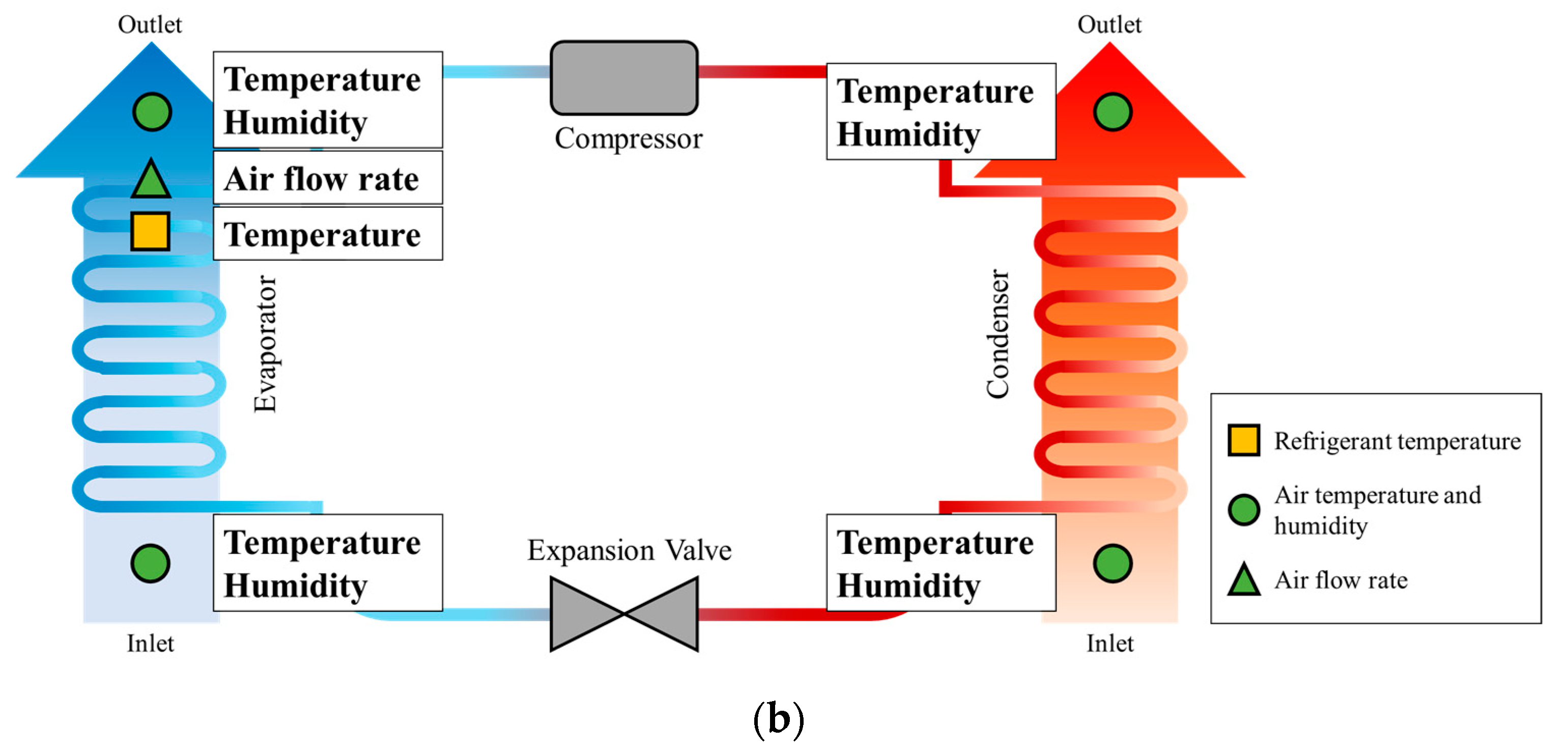
The measurement variables and design data were selected to estimate the air-side enthalpy change in the air-source heat pump system. For the refrigeration cycle measurement method, air-side measured data, evaporator air intake temperature and humidity, discharge temperature and humidity, discharge airflow rate, refrigerant temperature, and condenser-side air intake temperature and discharge temperature were selected as measured variables. Generally, the condenser-side airflow in air-source heat pump systems is controlled at constant airflow, so design data were used rather than measurements. A refrigeration cycle measurement method using design data was developed for the refrigerant flow rate required to calculate the enthalpy change on the refrigerant side. Table 1 lists the input and measurement variables of the measurement method, and Figure 4 shows a conceptual diagram of the measurement points of the input and measurement variables. The inlet and outlet air temperature, humidity, and airflow were measured with twenty-five node, T-type thermocouple grids and thermopile. Evaporator refrigerant temperature was collected by measuring the refrigerant surface temperature.
The difference between the measurement method for air-source heat pump systems proposed in this study and existing methods is the input and measurement variables. The existing method measures the refrigeration cycle by measuring the pressure and enthalpy of the refrigerant. If it is difficult to measure the enthalpy of a refrigerant, the enthalpy can be estimated by measuring the temperature and pressure of the refrigerant. The proposed measurement method uses the temperature and humidity of the inlet and outlet air of the evaporator and condenser, the supply airflow rate, and the evaporator refrigerant temperature, as the measurement variables. The evaporator refrigerant temperature is measured by the surface temperature of the refrigerant pipe of the evaporator. Figure 5 presents a schematic diagram of the difference between the existing and proposed methods.
The proposed refrigeration cycle measurement method was used to predict the COP and power consumption, which are the key operating data of the air-source heat pump system. The power consumption predicted by the refrigeration cycle method is the enthalpy change in the evaporator and condenser and can be expressed as Equation (10). The COP predicted using the refrigeration cycle is the enthalpy change in the evaporator and condenser, expressed as Equation (11).
W = m ˙ a i r h C o n d h E v a p
C O P = 1 h C o n d h E v a p 1
where h C o n d is the enthalpy change in air in a condenser in kJ/kg, h E v a p is the enthalpy change in air in an evaporator in kJ/kg.

2.3. Accuracy Analysis

The proposed refrigeration cycle measurement method was evaluated by measuring the difference between pressure and enthalpy according to the measured data. In addition, the reliability of the proposed refrigeration cycle measurement method was checked by comparing the difference between the two points and the maximum error range of the pressure and enthalpy measured values. The pressure of the refrigeration cycle in the pressure-enthalpy diagram was approximately 0 to 4 MPa, and the enthalpy was approximately 150 to 450 kJ/kg. Preprocessing was performed to evaluate the comparative analysis of pressure and enthalpy between the two points. The data were preprocessed using normalization. Normalization converts the data intervals into a range of 0 to 1, so the variables in different ranges have the same importance. The formula for data normalization is shown in Equation (12).
X n o r m a l = X X m i n X m a x X m i n
where X n o r m a l is the normalized values, X is the measurement values, X m i n is the minimum of measurement values, X m a x is the maximum of measurement values.
The statistics, data mining, and machine learning commonly use distance functions to quantify the similarity between data. The most common distance function is the Euclidean distance function. The closer the value of the distance function is to zero, the more similar the data used in the analysis are to each other, and it can be defined as Equation (13).
d ( h i , P i ) = i = 1 d h i P i 2
where d ( h , P ) is the distance between two points h and P , h is the enthalpy of refrigeration cycle in kJ/kg, and P is the pressure of refrigeration cycle in Pa.
The evaluation was performed using the Mean Bias Error (MBE) and the Coefficient of variation of root-mean-square error (Cv(RMSE)) proposed by ASHRAE Guideline 14. MBE and Cv(RMSE) can be calculated using Equations (14)–(16) [31].
M B E = i = 1 n P i M i n
R M S E = i = 1 n P i M i 2 n
C v R M S E = R M S E M ¯ × 100
where P is the predicted values, M is the measurement values, n is the number of data, M ¯ is the average of measurements.
Standard uncertainty and synthetic standard uncertainty analyses were performed to verify the reliability of the experimental data and computational results. When a measurement result is obtained from several different inputs, the standard uncertainty of this measurement result is called the synthetic standard uncertainty, and the synthesis is obtained using the law of propagation of uncertainty Equation (17) [32].
u c 2 y = i = 1 N f T 2 δ 2 T + j = 1 M f φ 2 δ 2 φ + k = 1 L f q 2 δ 2 q
where u c ( y ) is the combined standard uncertainty, f is the function, T is the measured temperature, φ is the: measured relative humidity, q is the measured airflow rate, δ ( T ) is the Uncertainty of the measured temperature, δ ( φ ) is the Uncertainty of the measured relative humidity, δ ( q ) is the Uncertainty of the measured airflow rate.

3. Case Study

3.1. Data Setup

There are difficulties in collecting air-source heat pump system operation data [33]. Therefore, the NIST [34] data on the refrigeration operating behavior of air-source heat pump systems were used to evaluate the refrigeration cycle measurement method developed in this study. The data were collected by operating a system using R410A [35,36,37], a refrigerant commonly used in domestic air-source heat pump systems. Table 2 lists the specifications of the air-source heat pump system and the system with a cooling capacity of 8.8 kW and a COP of 3.81.
The data were collected by attaching pressure transducers and T-type thermocouple probes to the inlet and outlet of all system components to measure the actual refrigerant pressure and temperature on the refrigerant side. The temperature was measured with an uncertainty of ±0.3 °C and the pressure with an uncertainty of ±1.0 Pa. The dew point and dry bulb temperatures were collected with an uncertainty of ±0.4 °C. The refrigerant mass flow rate was measured using a flow meter with an uncertainty of ±1.0%. The COP was calculated using the cooling capacity calculated from the refrigerant side measurement data, and the compressor power was measured using a watt–hour meter. The cooling capacity has an uncertainty of 4.0%, and the COP has an uncertainty of 5.5%. Table 3 lists the measurement ranges and uncertainties of the measurement devices used to measure the data.
Data were collected at indoor temperatures of 21.1 °C to 26.7 °C and an indoor humidity of 50%, with outdoor temperatures ranging from 21.1 °C to 37.8 °C and outdoor humidity ranging from 40 to 60%. The data collection conditions were selected based on ASHRAE Standard 37 [38] and ARI 210/240 Standards [39]. For the evaluation of the proposed refrigeration cycle measurement method, NIST data were used to evaluate the normal operation data in an environment that meets the conditions of indoor temperature 24.1 °C to 26.5 °C and outdoor temperature 26.0 °C to 36.6 °C, and Table 4 lists the environmental conditions of the data used for the evaluation.

3.2. Case of Analysis

Normal operation data from NIST data were used to evaluate the prediction results of the proposed refrigeration cycle measurement method. The inlet and outlet refrigerant pressures and temperatures of the evaporator and condenser were used as data for the existing refrigeration cycle measurement method. The performance of the air source heat pump system can change depending on the outdoor temperature. Therefore, the results of the refrigeration cycle measurement according to the outdoor temperature were compared and analyzed. Case 1 was selected as the operation data in the outdoor temperature range of 26 to 28 °C, and a total of 6 cases were selected in 2 °C intervals. For a total of 720 data sets, the proposed refrigeration cycle measurement method was compared with existing methods under various outdoor temperature conditions. The distance functions of enthalpy and pressure at each point were analyzed using Equation (13). Using the proposed method, the accuracy and measurement uncertainty of the COP and power consumption predicted using Equations (10) and (11) were confirmed.

4. Results and Discussion

4.1. Refrigeration Cycle

Figure 6 compares the refrigeration cycle and COP according to the measurement points during cooling operation at outdoor temperatures of 26 °C to 36.6 °C and indoor temperatures of 24 °C to 26 °C. The pressure increased as the temperature of the air exchanging heat with the evaporator and condenser increased. During the cooling operation, the pressure increased as the outdoor temperature increased, and the prediction results of the proposed refrigeration cycle measurement method confirmed the same pattern. The evaporator pressure changed proportionally with the change in indoor temperature, and the same pattern is confirmed by the proposed refrigeration cycle measurement method. COP variation with outdoor temperature. It was confirmed that the existing method and the proposed method have similar values. However, the difference in the enthalpy and pressure of the refrigeration cycle was noted, and the pressure and enthalpy were compared and analyzed to confirm the accuracy and reliability of the proposed method.
The refrigerant enthalpy and pressure of the refrigeration cycle predicted by the proposed method were compared with the measured values. The outlet enthalpy of the evaporator and the inlet enthalpy of the condenser were lower than the measured values, while the outlet enthalpy of the condenser and the inlet enthalpy of the evaporator were higher than the measured values. The outlet pressure of the evaporator and the outlet pressure of the condenser are lower than the measured values, and the outlet pressure of the condenser and the inlet pressure of the evaporator are higher than the measured values. This is because evaporation and condensation do not follow an ideal isobaric process in an actual refrigeration cycle. In the compression and expansion process, the isentropic and isenthalpic processes are the same as the theory, and the enthalpy difference at each point occurred due to superheating and subcooling in actual operation. The difference between the measured enthalpy and pressure is shown in Figure 7.
The range of the predicted data compared to the total measured data was analyzed by box-plot for the six cases based on the outdoor temperature. Figure 8 presents the range of refrigerant pressures and enthalpy measurement data used in the analysis and the refrigerant pressure and enthalpy at the condensation and evaporation inlet and outlet points calculated by the proposed refrigeration cycle measurement method. As shown in Figure 6, the enthalpy and pressure increased with the higher outdoor temperature. The predicted results for both pressure and enthalpy were within the range of the measured results. Therefore, the proposed refrigeration cycle can be used independently of performance changes due to outdoor temperature. Figure 8 presents the range of refrigerant pressures and enthalpy measurement data used in the analysis and the refrigerant pressure and enthalpy at the condensation and evaporation inlet and outlet points calculated by the proposed refrigeration cycle measurement method.
The measured results of the existing refrigeration cycle and the results of the proposed measurement method revealed an up to 0.03 MPa and 0.16 MPa difference in pressure in the evaporator and condenser, respectively, and an up to 11.23 kJ/kg and 17.13 kJ/kg difference in enthalpy in the evaporator and condenser, respectively. The pressure varied from 0.00 MPa to 0.16 MPa in all processes, with an average difference of 0.03 MPa. The enthalpy ranged from a minimum of 2.81 kJ/kg to a maximum of 17.13 kJ/kg, with an average difference of 7.78 kJ/kg. This is because evaporation and condensation do not follow an ideal isobaric process in an actual refrigeration cycle. In the compression and expansion process, the isentropic and isenthalpic processes are the same as the theory, and the enthalpy difference at each point occurred due to superheating and subcooling in actual operation. However, it was confirmed that the difference was less than 5% of the error of pressure and enthalpy. Figure 9 shows the results of analyzing the pressure and enthalpy difference between the existing refrigeration cycle measurement results and the predicted results.
Pressure and enthalpy have different units and ranges. Hence, the proposed refrigeration cycle prediction results were normalized and evaluated by calculating the distance function of the input and output points of each process of the refrigeration cycle. The difference between the input and output refrigerant pressure and enthalpy on the evaporator side and the input and output refrigerant pressure and enthalpy on the condenser side were large, as determined from the refrigerant temperature data of the evaporator. The distance function analysis between refrigeration cycles showed that the pressure had minimum and maximum values of 0 and 0.012, respectively, and the enthalpy had minimum and maximum values of 0.008 and 0.053, respectively. An analysis of the distance function of each point between refrigeration cycles by considering pressure and enthalpy simultaneously showed that the evaporator inlet showed a difference of 0.008 and a maximum of 0.035, and the evaporator outlet showed a difference of 0.015 and a maximum of 0.020. The condenser inlet and outlet had minimum and maximum differences of 0.013 and 0.053, respectively. Table 5 lists the results of the distance function analysis of pressure and enthalpy.
The refrigerant pressure and enthalpy measurements in the data used to develop the refrigeration cycle measurement method had an error of ±5%. The reliability of the proposed refrigeration cycle was evaluated by comparing the pressure and enthalpy with the maximum and minimum error values with a 5% error. The minimum and maximum pressures were 1.02 MPa and 2.67 MPa, respectively, and the minimum and maximum enthalpies were 237.94 kJ/kg and 491.45 kJ/kg, respectively. The difference between the pressure and enthalpy minimum and maximum values and their 5% tolerance was 0.05 MPa minimum and 0.13 MPa maximum for the pressure and 11.9 kJ/Kg minimum and 24.57 kJ/kg maximum for the enthalpy. In addition, a comparison of the distance function between the evaporation and condensation inlet and outlet points showed that the distance function has a minimum of 0.037 and a maximum of 0.077 when an error of 5% occurs in both pressure and enthalpy. The maximum distance function between the existing refrigeration cycle measurement results and the prediction results of the measurement method was smaller than the distance function value for a maximum error of 5%. Therefore, the proposed refrigeration cycle measurement method is reliable.

4.2. Prediction of Power Consumption and COP

The data prediction results using the proposed refrigeration cycle measurement method were evaluated. Equations (14)–(16) enthalpy change in the refrigerant resulting from the proposed measurement method using the power consumption calculated using Equation (10). The power consumption was evaluated using the data collected by the watt–hour meter. Equations (14)–(16) were used to assess the accuracy of the COP calculated using Equation (11) using the enthalpy change in the refrigerant resulting from the proposed measurement method. The power consumption measured by the watt–hour meter of the air-source heat pump system and the power consumption prediction result were compared and analyzed, and the results are shown in Figure 10. The prediction result revealed an MBE of 0.15% and Cv(RMSE) of 8.97%. The R2 of the predicted for the measured power consumption is 0.87, and it is confirmed that most of the predicted results are within ± standard deviation of the measured values.
The COP calculated using the existing refrigeration cycle measurement method, and the COP prediction results are compared and analyzed, as shown in Figure 11. The MBE and Cv(RMSE) were 0.04% and 7.14%, respectively. The R2 of the performance prediction results was 0.98, confirming that all predicted results were within ± standard deviation of the measured values. The measurement uncertainties of power consumption and COP are ±4.06% and ±2.24%, respectively, and the prediction results of power consumption and COP are shown in Table 6.

5. Conclusions

This study developed a refrigeration cycle prediction model for an air-source heat pump system using air-side measurement data that are easy to measure in situ. The main operation data, COP, and cooling capacity, were predicted using the proposed prediction model, and the results were evaluated. The proposed refrigeration cycle measurement method of the air-source heat pump system was analyzed and evaluated using the data from NIST. The air enthalpy change calculation method was summarized by measuring the temperature and humidity of the inlet and outlet air of the evaporator and condenser of the air-source heat pump system. The refrigerant enthalpy change calculation method was summarized using the air enthalpy change and airflow rate. A refrigeration cycle measurement method that considers the characteristics of evaporation, compression, condensation, and expansion processes was proposed by dividing it into five steps. The proposed refrigeration cycle measurement method was evaluated by comparing the refrigerant pressure and enthalpy of evaporation and condensation inlet and outlet points with the existing refrigeration cycle. The differences between the refrigerant pressure and enthalpy at each point and the distance function after normalization were analyzed, and the distance function of the maximum error of the pressure and enthalpy measurement device was compared with that of the total data used in the analysis. All data had low distance function values compared to the maximum error, confirming the reliability of the proposed refrigeration cycle measurement method. The power consumption predicted using the proposed measurement method and the power consumption measured by the watt–hour meter were compared. In addition, the COP prediction value of the proposed refrigeration cycle and the existing refrigeration cycle measurement results were analyzed. The MBE of the power consumption and COP predicted using the proposed refrigeration cycle measurement results was 0.15% and 0.04%, respectively, and the Cv(RMSE) was 8.967% and 7.14%, respectively. This confirmed that the measurement data validation criteria presented in ASHRAE Guideline 14 were met. Moreover, the measurement uncertainties of power consumption and COP are ±4.06% and ±2.24%, respectively. The refrigeration cycle measurement method developed in this study is expected to complement the limitations of technologies that can reduce energy consumption, such as fault detection and diagnosis technology and performance improvement control measures.

Author Contributions

All authors contributed to this work. H.-G.L. investigated and wrote the original draft; Y.-H.C. carried out project administration and supervisor; H.-J.K. gave investigation and resources. All authors have read and agreed to the published version of the manuscript.

Funding

This work was supported by the Korea Institute of Energy Technology Evaluation and Planning (KETEP) and the Ministry of Trade, Industry & Energy (MOTIE) of the Republic of Korea (No. 20202020800360).

Institutional Review Board Statement

Not applicable.

Informed Consent Statement

Not applicable.

Data Availability Statement

Not applicable.

Conflicts of Interest

The authors declare no conflict of interest.

References

  1. IEA. Key World Energy Statistics; IEA: Paris, France, 2009.
  2. Yang, L.; Yan, H.; Lam, J.C. Thermal comfort and building energy consuimption implications—A review. Appl. Energy 2014, 115, 164–173. [Google Scholar] [CrossRef]
  3. Chung, W. Review of building energy-use performance benchmarking methodologies. Appl. Energy 2011, 88, 1470–1479. [Google Scholar] [CrossRef]
  4. Franco, A.; Miserocchi, L.; Testi, D. HVAC Energy Saving Strategies for Public Buildings Based on Heat Pumps and Demand Controlled Ventilation. Energies 2021, 14, 5541. [Google Scholar] [CrossRef]
  5. Ding, Y.; Chai, Q.; Ma, G.; Jiang, Y. Experimental study of an improved air source heat pump. Energy Convers. Manag. 2004, 45, 2393–2403. [Google Scholar] [CrossRef]
  6. Xu, Z.; Zhao, W.; Shao, S.; Wang, Z.; Xu, W.; Li, H.; Wang, Y.; Wang, W.; Yang, Q.; Xu, C. Analysis on key influence factors of air source heat pumps with field monitored data in Beijing. Sustain. Energy Technol. Assess. 2021, 48, 101642. [Google Scholar] [CrossRef]
  7. Wang, W.; Ma, Z.; Jiang, Y.; Yang, Y.; Xu, S.; Yang, Z. Field test investigation of a double-stage coupled heat pumps heating system for cold regions. Int. J. Refrig. 2005, 28, 672–679. [Google Scholar] [CrossRef]
  8. Chua, K.J.; Chou, S.K.; Yang, W.M. Advances in heat pump systems: A review. Appl. Energy 2010, 87, 3611–3624. [Google Scholar] [CrossRef]
  9. Song, M.; Mao, N.; Xu, Y.; Deng, S. Challenges in, and the development of, building energy saving techniques, illustrated with the example of an air source heat pump. Therm. Sci. Eng. Prog. 2019, 10, 337–356. [Google Scholar] [CrossRef]
  10. Breuker, M.S. Evaluation of a Statistical, Rule-Based Detection an Diagnosis Method for Vapor Compression Air Conditioners. Master’s Thesis, School of Mechanical Engineering, Purdue University, West Lafayette, IN, USA, 1997. [Google Scholar]
  11. Chen, B. Evaluating the Potential of On-Line Fault Detection and Diagnosis for Rooftop Air Conditioners. Master’s Thesis, School of Mechanical Engineering, Purdue University, West Lafayette, IN, USA, 2000. [Google Scholar]
  12. Li, H. A Decoupling-Based Unified Fault Detection and Diagnosis Approach for Packaged Air Conditioners. Ph.D. Thesis, Purdue University, West Lafayette, IN, USA, 2004. [Google Scholar]
  13. Li, W.-T.; Hassan, N.U.; Khan, F.; Yuen, C.; Keow, Y.M. Data Driven Model for Performance Evaluation and Anomaly Detection in Integrated Air Source Heat Pump Operation. In Proceedings of the 2019 IEEE International Conference on Industrial Technology (ICIT), Melbourne, Australia, 13–15 February 2019; pp. 1280–1285. [Google Scholar]
  14. Xu, Z.; Li, H.; Shao, S.; Xu, W.; Wang, Z.; Wang, Y.; Sun, X.; Yang, Q.; Xu, C.; Zhao, W. A semi-theoretical model for energy efficiency assessment of air source heat pump systems. Energy Convers. Manag. 2021, 228, 113667. [Google Scholar] [CrossRef]
  15. Lyons, P.; Pukhrem, S.; Walsh, A.; Carroll, P. Review of LV Network Development and Design for Electrified Domestic Heat and Transport. In Proceedings of the 3rd E-Mobility Power System Integration Symposium, Dublin, Ireland, 14 October 2019. [Google Scholar]
  16. Kim, E.; Lee, J.; Jeong, Y.; Hwang, Y.; Lee, S.; Park, N. Performance evaluation under the actual operating condition of a vertical ground source heat pump system in a school building. Energy Build. 2012, 50, 1–6. [Google Scholar] [CrossRef]
  17. Tabatabaei, S.A.; Treur, J.; Waumans, E. Comparative Evaluation of Different Computational Models for Performance of Air Source Heat Pumps Based on Real World Data. Energy Procedia 2016, 95, 459–466. [Google Scholar] [CrossRef]
  18. Cho, H.; Cho, K.; Yoo, H.; Hong, H. Field performance of variable capacity heat pump systems with multi-indoor units during Cooling Season. In Proceeding of the SAREK 2005 Summer Annual Conference, Huston, Pyeongchang, Republic of Korea, 29 June–1 July 2005; pp. 1137–1142. [Google Scholar]
  19. Zhang, G.; Liu, W.; Xiao, H.; Shi, W.; Wang BLi, X.; Cao, Y. New method for measuring field performance of variable refrigerant flow systems based on compressor set energy conservation. Appl. Therm. Eng. 2019, 154, 530–539. [Google Scholar] [CrossRef]
  20. Cong, T.; Noel, D.; Riviere, P.; Arzano, C.; Marchio, D. In-situ method for air-to-air heat pump seasonal performance determination including steady-state and dynamic operation. Int. J. Refrig. 2021, 127, 239–249. [Google Scholar]
  21. Xiao, H.; Yang, Z.; Shi, J.; Wang, B.; Shi, W. Method for performance metering of indoor units in variable refrigerant flow systems based on built-in sensors. Appl. Therm. Eng. 2021, 196, 1–13. [Google Scholar] [CrossRef]
  22. Chesser, M.; Lyons, P.; O’Reilly, P.; Carroll, P. Air source heat pump in-situ performance. Energy Build. 2021, 251, 111365. [Google Scholar] [CrossRef]
  23. Eom, Y.H.; Chung, Y.; Park, M.; Hong, S.B.; Kim, M.S. Deep learning-based prediction method on performance change of air source heat pump system under frosting conditions. Energy 2021, 228, 120542. [Google Scholar] [CrossRef]
  24. Ye, K.; Demirezen, G.; Fung, A.S.; Janssen, E. The use of artificial neural networks (ANN) in the prediction of energy consumption of air-source heat pump in retrofit residential housing. IOP Conf. Ser. Earth Environ. Sci. 2020, 463, 012165. [Google Scholar] [CrossRef]
  25. Eom, Y.H.; Yoo, J.W.; Hong, S.B.; Kim, M.S. Refrigerant charge fault detection method of air source heat pump system using convolutional neural network for energy saving. Energy 2019, 187, 115877. [Google Scholar] [CrossRef]
  26. Yan, L.; Hu, P.; Li, C.; Yao, Y.; Xing, L.; Lei, F.; Zhu, N. The performance prediction of ground source heat pump system based on monitoring data and data mining technology. Energy Build. 2016, 127, 1085–1095. [Google Scholar] [CrossRef]
  27. Han, D.; Chang, Y.S.; Kim, Y. Performance analysis of air source heat pump system for office building. J. Mech. Sci. Technol. 2016, 30, 5257–5268. [Google Scholar] [CrossRef]
  28. Danza, L.; Belussi, L.; Meroni, I.; Mililli, M.; Salamone, F. Hourly Calculation Method of Air Source Heat Pump Behavior. Buildings 2016, 6, 16. [Google Scholar] [CrossRef] [Green Version]
  29. Carroll, P.; Chesser, M.; Lyons, P. Air Source Heat Pumps field studies: A systematic literature review. Renew. Sustain. Energy Rev. 2020, 134, 110275. [Google Scholar] [CrossRef]
  30. Soni, J.; Gupta, R.C. Performance Analysis of Vapour Compression Refrigeration System with R404A, R407C and R410A. Int. J. Mech. Eng. Robot. Res. 2013, 2, 25–26. [Google Scholar]
  31. ASHRAE 14-2014; Measurement of Energy, Demand, and Water Savings. American Society of Heating, Refrigerating, and Air Conditioning Engineers: Atlanta, GA, USA, 2014.
  32. Taylor, B.N.; Kuyatt, C.E. Guidelines for Evaluating and Expressing the Uncertainty of NIST Measurement Results; NIST Technical Note 1297; National Institute of Standards and Technology: Gaithersburg, MD, USA, 1994. [Google Scholar]
  33. De La Cruz, A.T.; Riviere, P.; Marchio, D.; Cauret, O.; Milu, A. Hardware in the loop test bench using Modelica: A platform to test and improve the control of heating systems. Appl. Energy 2017, 188, 107–120. [Google Scholar] [CrossRef]
  34. Kim, M.; Payne, W.V.; Domanski, P.A.; Hermes, C.J.L. Performance of a Residential Heat Pump Operating in the Cooling Mode with Single Faults Imposed; NIST Interagency/Internal Report (NISTIR) 7350; National Institute of Standards and Technology: Gaithersburg, MD, USA, 2006. [Google Scholar]
  35. Palmiter, L.; Kim, J.H.; Larson, B.; Francisco, P.W.; Groll, E.A.; Braun, J.E. Measured effect of airflow and refrigerant charge on the seasonal performance of an air-source heat pump using R-410A. Energy Build. 2011, 43, 1802–1810. [Google Scholar] [CrossRef]
  36. Bertsch, S.S.; Groll, E.A. Two-stage air-source heat pump for residential heating and cooling applications in northern U.S. climates. Int. J. Refrig. 2008, 31, 1282–1292. [Google Scholar] [CrossRef]
  37. Bertsch, S.S.; Groll, E.A. Air source heat pump for northern climates part I: Simulation of different heat pump cycles. In Proceedings of the International Refrigeration and Air Conditioning Conference, West Lafayette, IN, USA, 17–20 July 2006. [Google Scholar]
  38. ANSI/ASHRAE 37-1988; Methods of Testing for Rating Unitary Air-Conditioning and Heat Pump Equipment. American Society of Heating, Refrigerating, and Air-Conditioning Engineers, Inc.: Atlanta, GA, USA, 1988.
  39. ARI 210/240-2006; Standard for Unitary Air Conditioning and Air Source Heat Pump Equipment. Air Conditioning and Refrigeration Institute: Fairfax, VA, USA, 2006.
Figure 1. Refrigeration cycle of an air-source heat pump.
Applsci 13 09060 g001
Figure 2. Conceptual diagram of the refrigeration cycle measurement method.
Applsci 13 09060 g002
Figure 4. Schematic diagram of the measurement points.
Applsci 13 09060 g004
Figure 5. Comparison of existing (a) and proposed method (b).
Applsci 13 09060 g005aApplsci 13 09060 g005b
Figure 6. Results of refrigeration cycle measurement.
Applsci 13 09060 g006aApplsci 13 09060 g006b
Figure 7. Results of enthalpy and pressure prediction.
Applsci 13 09060 g007aApplsci 13 09060 g007b
Figure 8. Range of accuracy analysis for the proposed method.
Applsci 13 09060 g008aApplsci 13 09060 g008bApplsci 13 09060 g008c
Figure 9. Range of enthalpy and pressure differences between actual data and the proposed method.
Applsci 13 09060 g009
Figure 10. Comparisons of the predicted and actual power consumption measurements for the system.
Applsci 13 09060 g010
Figure 11. Comparisons of the predicted and actual COP measurements for the system.
Applsci 13 09060 g011
Table 1. Description of the measurement variables.
MeasurementSymbolsUnit
Evaporator inlet air temperature t E v a p , i n °C
Evaporator outlet air temperature t E v a p , o u t °C
Evaporator refrigerant temperature t E v a p , r e f °C
Evaporator inlet air relative humidity φ E v a p , i n %
Evaporator outlet air relative humidity φ E v a p , o u t %
Evaporator outlet airflow rate q E v a p , o u t m3/s
Condenser inlet air temperature t C o n d , i n °C
Condenser outlet air temperature t C o n d , o u t °C
Condenser outlet airflow rate q C o n d , a i r m3/s
Refrigerant flow rate m ˙ r e f kg/s
Table 2. System descriptions for air source heat pump.
CategorySpecification
Used refrigerantR410A
Cooling capacity8.8 kW
COP3.81
Table 3. Measurement uncertainties.
MeasurementRangeUncertainty
Temperature Difference0 °C to 28 °C±0.3 °C
Air Nozzle Pressure0 Pa to 1245 Pa±1.0 Pa
Refrigerant Mass Flow Rate0 kg/h to 544 kg/h±1.0%
Dew point Temperature0 °C to 37.8 °C±0.4 °C
Dry-Bulb Temperature0 °C to 37.8 °C±0.4 °C
Total Cooling Capacity4.4 kW to 10.5 kW4.0%
COP2.5 to 6.05.5%
Table 4. Operating conditions for accuracy analysis.
CategoryContents
Indoor temperature24.1 °C to 26.5 °C
Outdoor temperature26.0 °C to 36.6 °C
Indoor relative humidity50%
Outdoor relative humidity40% to 60%
Table 5. Range of distance function differences between actual data and the proposed method.
CategoryEvaporator InletEvaporator OutletCondenser InletCondenser OutletTotal
P Min0.0000.0000.0000.0000.000
Max0.0000.0030.0120.0040.012
Average0.0000.0010.0050.0010.002
h Min0.0080.0150.0130.0080.008
Max0.0350.0200.0530.0350.053
Average0.0250.0180.0280.0250.024
d ( h , P ) Min0.0080.0150.0130.00080.012
Max0.0350.0200.0530.0350.053
Average0.0260.0180.0260.0260.026
Table 6. Accuracy analysis result.
CategoryMBECv(RMSE)R2Uncertainty
Power consumption0.15%8.97%0.86±4.06%
COP0.04%7.14%0.98±2.24%
Disclaimer/Publisher’s Note: The statements, opinions and data contained in all publications are solely those of the individual author(s) and contributor(s) and not of MDPI and/or the editor(s). MDPI and/or the editor(s) disclaim responsibility for any injury to people or property resulting from any ideas, methods, instructions or products referred to in the content.

