
Study on the Effect of Large Cross-Section Quasi-Rectangular Pipe Jacking near Side Crossing Viaduct Piles in Soft Soil Areas
Abstract
:1. Introduction
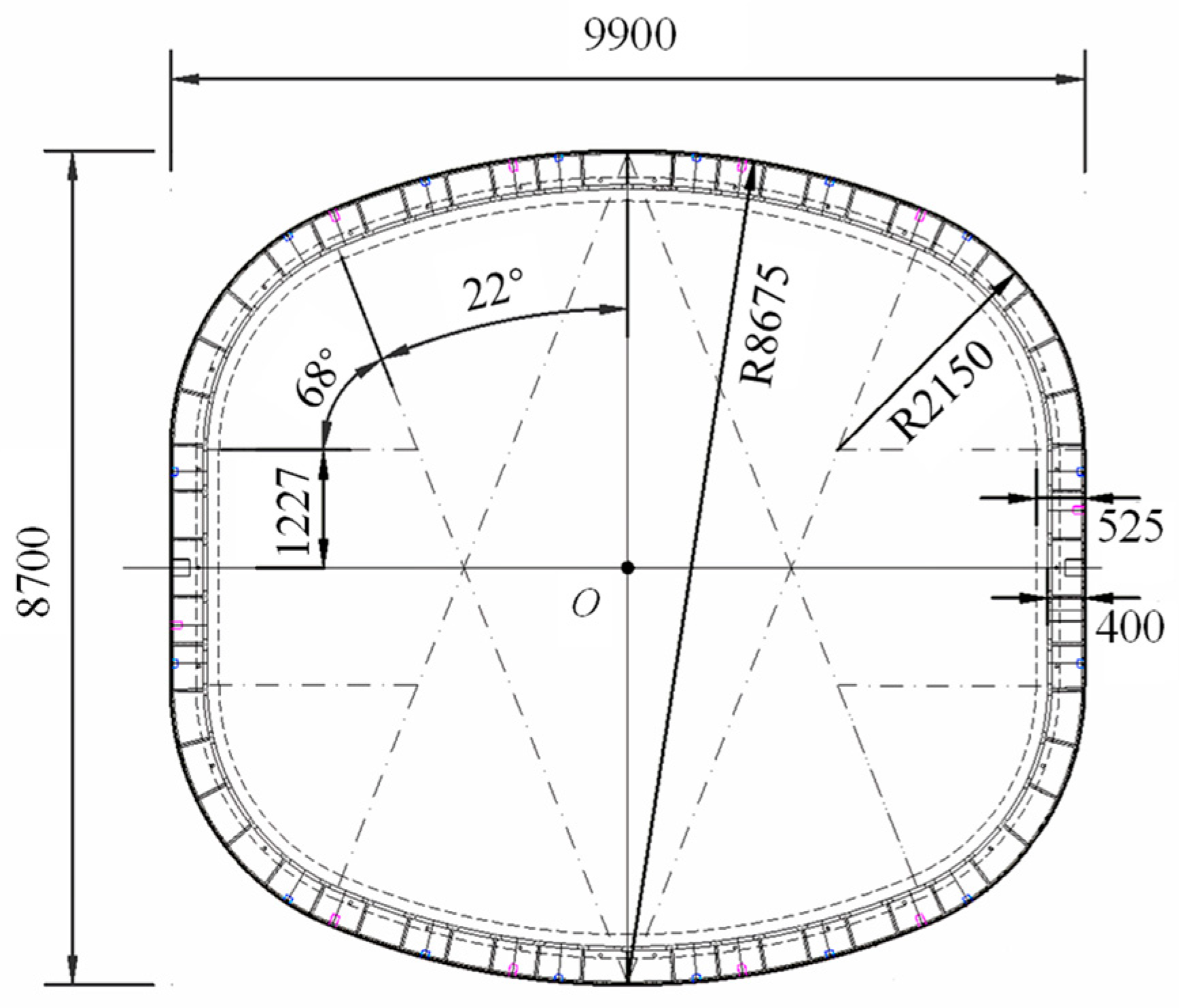
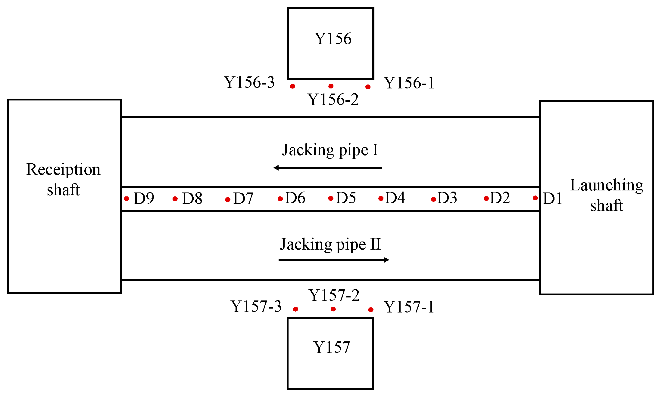
2. Project Profile
3. Model Building
3.1. Equivalent Modeling of Pipe Sections for Quasi-Rectangular Jacking Pipes
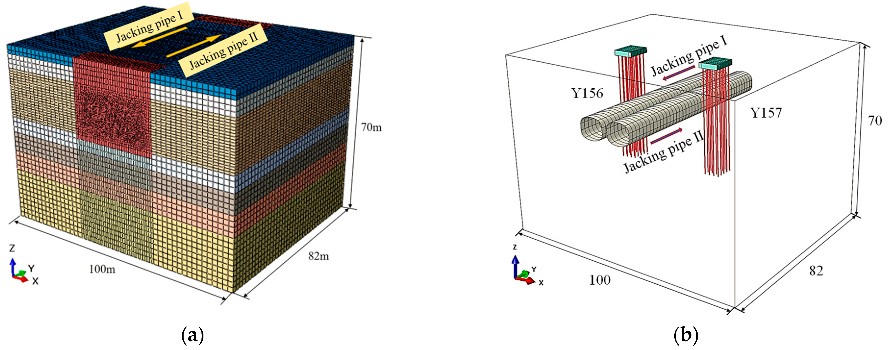
3.2. Numerical Model and Constitutive Parameters
3.3. Simulation of Construction Steps
4. Results Analysis
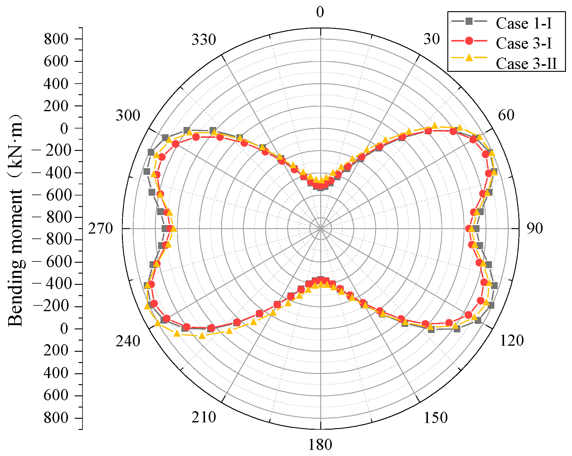
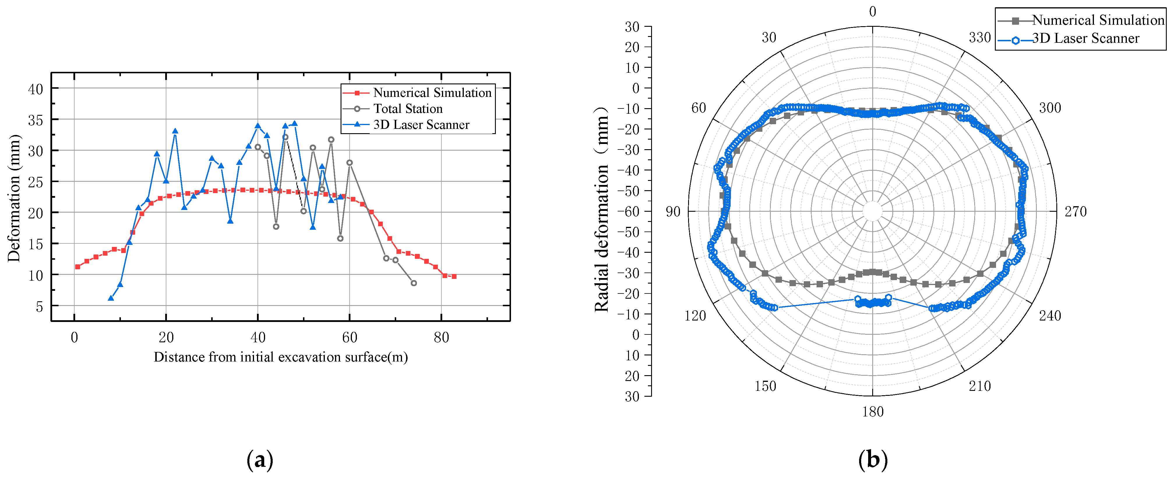
4.1. Deformation Analysis of Pipe Jacking Section
4.2. Surface Settlement Analysis
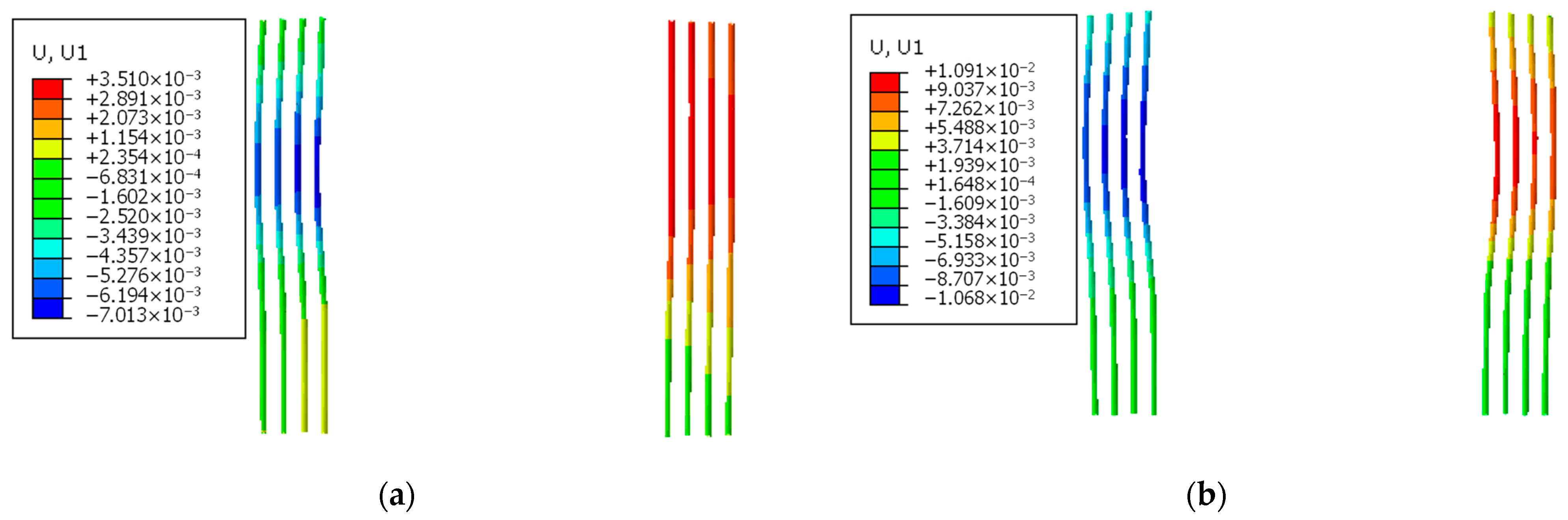
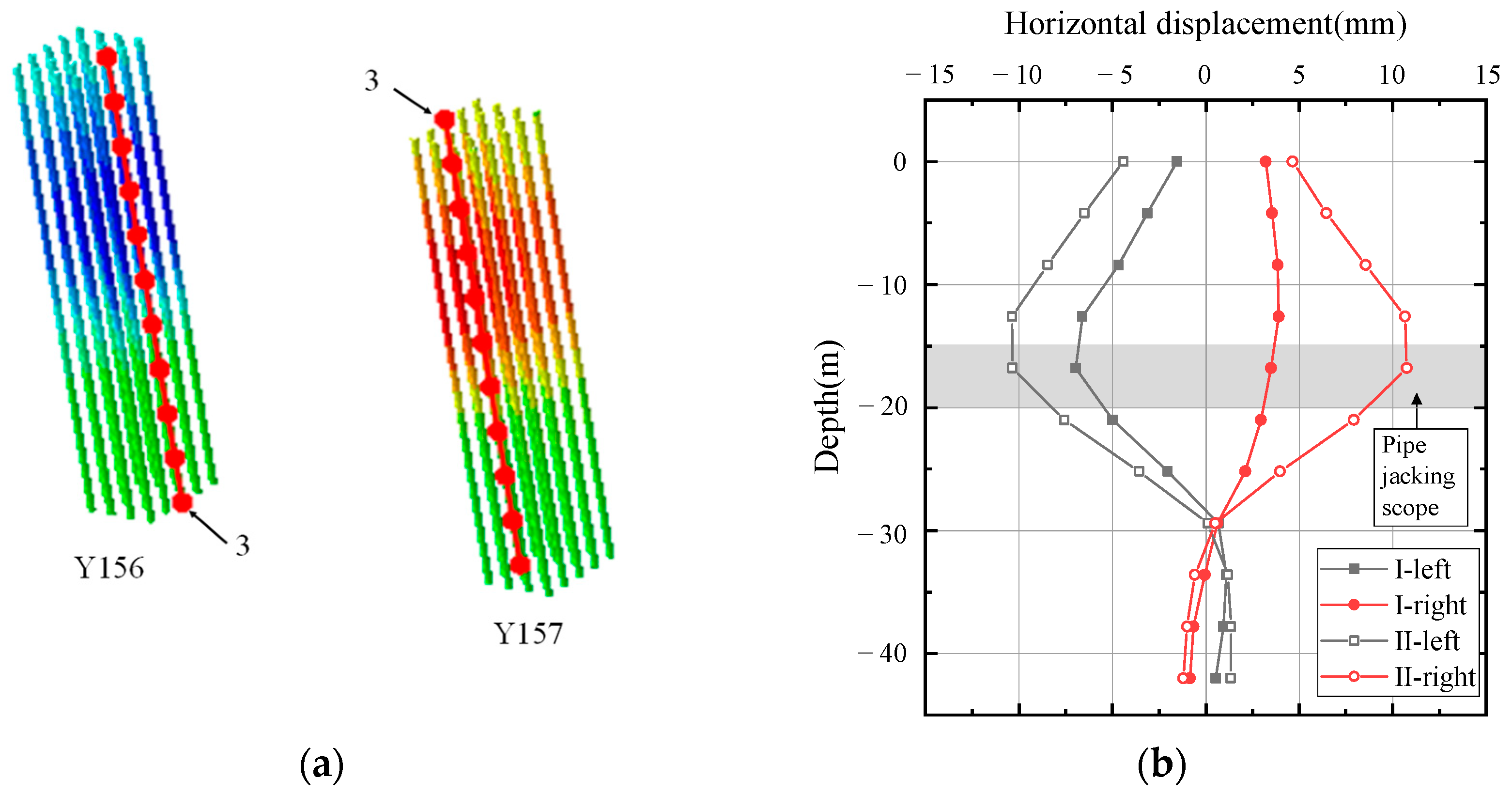
4.3. Pile Deformation Analysis
5. Monitoring Program and Results
5.1. Monitoring of Pipe Jacking Deformation
5.2. Monitoring of Soil Displacement
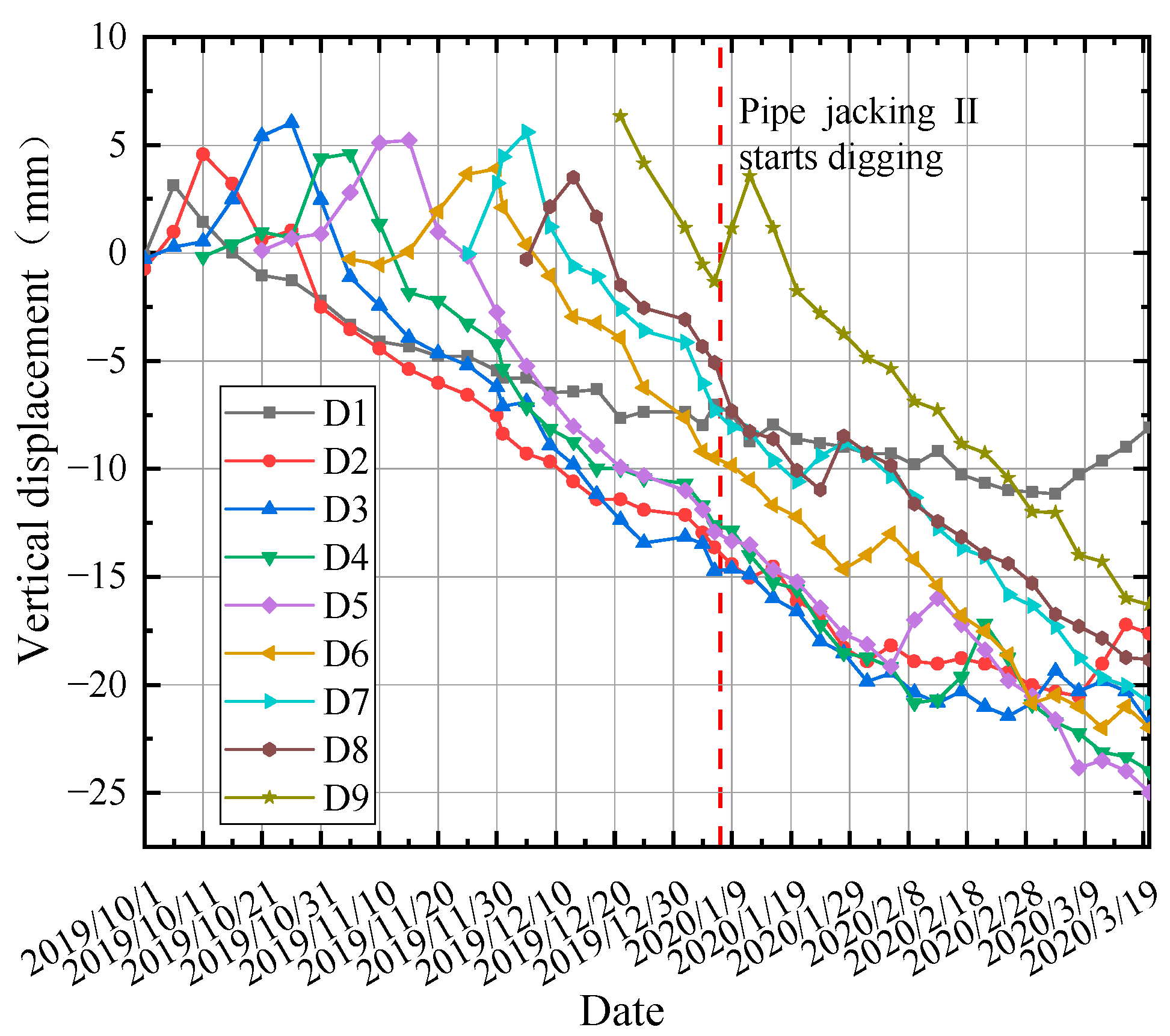
5.2.1. Surface Subsidence Analysis
5.2.2. Deep Lateral Displacement of Soil
6. Conclusions
Author Contributions
Funding
Institutional Review Board Statement
Informed Consent Statement
Data Availability Statement
Acknowledgments
Conflicts of Interest
References
- Sterling, R.L. Developments and Research Directions in Pipe Jacking and Microtunneling. Undergr. Space 2018, 5, 1–19. [Google Scholar] [CrossRef]
- Jianbin, L. Key Technologies and Applications of the Design and Manufacturing of Non-Circular TBMs. Engineering 2017, 3, 905–914. [Google Scholar]
- Chen, X.; Ma, B.; Najafi, M.; Zhang, P. Long rectangular box jacking project: A case study. Undergr. Space 2019, 6, 101–125. [Google Scholar] [CrossRef]
- Shimada, H.; Khazaei, S.; Matsui, K. Small diameter tunnel excavation method using slurry pipe-jacking. Geotech. Geol. Eng. 2004, 22, 161–186. [Google Scholar] [CrossRef]
- Sun, J. Research on environmental soil engineering works during underground construction activities in ubran area. Undergrourd Eng. Tunmels 1999, 3, 2–6. [Google Scholar]
- Lu, A.Z.; Xu, G.S.; Sun, F.; Sun, W.Q. Elasto-plastic analysis of a circular tunnel including the effect of the axial in situ stress. Int. J. Rock Mech. Min. Sci. 2010, 1, 50–59. [Google Scholar] [CrossRef]
- Dafalla, M.; Aldeghaither, S.; Taha, N.; Al-Laham, M.; Al-Zoubi, L. Efficient Pile Distribution for Piled-Raft Foundations for Tall Buildings. In Geo-Congress 2020; 1st Session on Foundations, Soil Improvement, and Erosion at Geo-Congress on Vision, Insight, Outlook; American Society of Civil Engineers: Reston, VA, USA, 2020; Volume 315, pp. 246–255. [Google Scholar]
- Zhou, S.; Wang, Y.; Huang, X. Experimental study on the effect of injecting slurry inside a jacking pipe tunnel in silt stratum. Tunn. Undergr. Space Technol. 2009, 24, 466–471. [Google Scholar] [CrossRef]
- Shou, K.; Yen, J.; Liu, M. On the frictional property of lubricants and its impact on jacking force and soil-pipe interaction of pipe-jacking. Tunn. Undergr. Space Technol. 2010, 25, 469–477. [Google Scholar] [CrossRef]
- Soomro, M.A.; Kumar, M.; Xiong, H.; Mangnejo, D.A.; Mangi, N. Investigation of effects of different construction sequences on settlement and load transfer mechanism of single pile due to twin stacked tunnelling. Tunn. Undergr. Space Technol. Inc. Trenchless Technol. Res. 2020, 96, 103171. [Google Scholar] [CrossRef]
- Peck, R.B. Deep excavations and tunneling in soft ground. In Proceedings of the 7th International Conference on Soil Mechanics and Foundation Engineering; Sociedad Mexicana de Mecanica: Mexico City, Mexico, 1969; pp. 147–150. [Google Scholar]
- Yang, X.; Li, Y.S. Research of surface settlement for a single arch long-span subway station using the Pipe-roof Pre-construction Method. Tunn. Undergr. Space Technol. Inc. Trenchless Technol. Res. 2018, 72, 210–217. [Google Scholar] [CrossRef]
- Li, R.; Lei, H.; Liu, Y.; Zhang, Y.; Hu, Y. Ground Movement and Existing Tunnel Deformation Induced by Overlapped Tunneling. Int. J. Geomech. 2022, 22, 04022098. [Google Scholar] [CrossRef]
- Wang, Y.Z.; Zhang, D.L.; Fang, Q.; Liu, X.; Wang, J.C. Analytical Solution on Ground Deformation Caused by Parallel Construction of Rectangular Pipe Jacking. Appl. Sci. 2022, 12, 3298. [Google Scholar] [CrossRef]
- Ma, W.; Wang, B.; Wang, X.; Zhou, S.; Wang, B. Soil Layer Disturbance Caused by Pipe Jacking: Measurement and Simulation of a Case Study. KSCE J. Civ. Eng. 2021, 25, 1467–1478. [Google Scholar] [CrossRef]
- Zhang, X.; Jiang, Y.; Cai, Y.; Li, X.; Golsanami, N.; Wang, X.; Hao, J.; Li, N.; Wu, F.; Wang, X. A Simplified Method for Predicting Tunneling-Induced Ground Movement considering Nonuniform Deformation Boundary. Shock Vib. 2022, 2022, 6289303. [Google Scholar] [CrossRef]
- Sheil, B.B.; Suryasentana, S.K.; Templeman, J.O.; Phillips, B.M.; Cheng, W.C.; Zhang, L. Prediction of Pipe-Jacking Forces Using a Bayesian Updating Approach. J. Geotech. Geoenvironmental Eng. 2021, 148, 04021173. [Google Scholar] [CrossRef]
- Ma, P.; Shimada, H.; Sasaoka, T.; Hamanaka, A.; Moses, D.N.; Dintwe, T.K.; Matsumoto, F.; Ma, B.; Huang, S. A new method for predicting the friction resistance in rectangular pipe-jacking. Tunn. Undergr. Space Technol. 2022, 123, 104–338. [Google Scholar] [CrossRef]
- Wen, K.; Shimada, H.; Zeng, W.; Sasaoka, T.; Qian, D.Y. Frictional analysis of pipe-slurry-soil interaction and jacking force prediction of rectangular pipe jacking. Eur. J. Environ. Civ. Enginecring 2020, 24, 814. [Google Scholar] [CrossRef]
- Pan, Z.; Du, K.; Lv, F.; Tao, S. Numerical Simulation of Mechanical Response of Bridge Foundation and Existing Tunnel Caused by Pipe Jacking Construction. J. Phys. Conf. Ser. 2022, 2230, 012008. [Google Scholar] [CrossRef]
- Soudarissanane, S.; Lindenbergh, R.; Menenti, M.; Teunissen, P. Scanning geometry: Influencing factor on the quality of terrestrial laser scanning points. ISPRS J. Photogramm. Remote Sens. 2011, 66, 389–399. [Google Scholar] [CrossRef]


| Soil Layer | The Name of the Soil | Thickness (m) | Density (kg/m3) | Cohesion (kPa) | Angle of Internal Friction (°) | Modulus of Elasticity (MPa) | Poisson’s Ratio | |
|---|---|---|---|---|---|---|---|---|
| 1 | ①1-1 miscellaneous fill | 3.4 | 1900 | 9.0 | 15.00 | 10 | 0.33 | 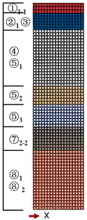 |
| 2 | ②1 clay | 5.6 | 1805 | 13.4 | 15.06 | 14.4 | 0.33 | |
| ③mucky silty clay | ||||||||
| 3 | ④mucky clay | 19.2 | 1803 | 16.1 | 13.99 | 38.4 | 0.35 | |
| ⑤1 clay | ||||||||
| 4 | ⑤2 silty clay+ silt | 6.1 | 1880 | 13.0 | 24.50 | 79.5 | 0.31 | |
| 5 | ⑤3 silty clay | 7.7 | 1887 | 23.4 | 21.08 | 92.5 | 0.31 | |
| 6 | ⑦2-2 silt | 7.9 | 1990 | 6.0 | 33.63 | 214 | 0.26 | |
| 7 | ⑧1 clay | 20.1 | 1863 | 24.4 | 18.40 | 80 | 0.33 | |
| ⑧2 silty clay+ silt | ||||||||
| The grouting layer | / | 0.03 | 1200 | / | / | 1.5 | 0.45 |
| Structure | Modulus of Elasticity (GPa) | Poisson’s Ratio | Density (kg/m3) | Sizes |
|---|---|---|---|---|
| Pile | 38 | 0.3 | 2500 | Φ600 mm × 42 m |
| bearing platform | 28 | 0.2 | 2500 | 8.4 m × 6.6 m × 2 m |
| Date | The 25th Ring | The 26th Ring | The 31st Ring |
|---|---|---|---|
| 25 January 2020 | The reinforcement area (4 m) | The reinforcement area (2 m) | — |
| 5 February 2020 | The normal advancement area (16 m) | The normal advancement area (14 m) | The reinforcement area (4 m) |
| 18 February 2020 | The normal advancement area (34 m) | The normal advancement area (32 m) | The normal advancement area (22 m) |
| Serial Number | Starting Value | 25 January 2020 | 5 February 2020 | 18 February 2020 | Cumulative Deformation |
|---|---|---|---|---|---|
| The 25th ring | 9307.6 | +19.9 | +5.7 | −4.8 | +20.8 |
| The 26th ring | 9329.7 | +6.1 | +8.5 | −1.0 | +13.6 |
| The 31st ring | 9327.5 | / | +3.3 | +2.5 | +5.8 |
Disclaimer/Publisher’s Note: The statements, opinions and data contained in all publications are solely those of the individual author(s) and contributor(s) and not of MDPI and/or the editor(s). MDPI and/or the editor(s) disclaim responsibility for any injury to people or property resulting from any ideas, methods, instructions or products referred to in the content. |
© 2023 by the authors. Licensee MDPI, Basel, Switzerland. This article is an open access article distributed under the terms and conditions of the Creative Commons Attribution (CC BY) license (https://creativecommons.org/licenses/by/4.0/).
Share and Cite
Yan, Y.; Zhang, M.; Cao, M. Study on the Effect of Large Cross-Section Quasi-Rectangular Pipe Jacking near Side Crossing Viaduct Piles in Soft Soil Areas. Appl. Sci. 2023, 13, 9799. https://doi.org/10.3390/app13179799
Yan Y, Zhang M, Cao M. Study on the Effect of Large Cross-Section Quasi-Rectangular Pipe Jacking near Side Crossing Viaduct Piles in Soft Soil Areas. Applied Sciences. 2023; 13(17):9799. https://doi.org/10.3390/app13179799
Chicago/Turabian StyleYan, Yichen, Mengxi Zhang, and Mengjia Cao. 2023. "Study on the Effect of Large Cross-Section Quasi-Rectangular Pipe Jacking near Side Crossing Viaduct Piles in Soft Soil Areas" Applied Sciences 13, no. 17: 9799. https://doi.org/10.3390/app13179799