Article

Study on the Effect of Large Cross-Section Quasi-Rectangular Pipe Jacking near Side Crossing Viaduct Piles in Soft Soil Areas

School of Mechanism and Engineering Science, Shanghai University, Shanghai 200444, China
*
Author to whom correspondence should be addressed.
Appl. Sci. 2023, 13(17), 9799; https://doi.org/10.3390/app13179799
Submission received: 7 August 2023 / Revised: 26 August 2023 / Accepted: 28 August 2023 / Published: 30 August 2023
(This article belongs to the Section Civil Engineering)

Abstract

:
Due to its high section use rate and minimal environmental impact, pipe jacking technology is frequently utilized in the building of urban rail transit and other municipal projects. This paper develops a three-dimensional numerical model for the gradual construction of rectangular pipe jacking based on the quasi-rectangular pipe jacking metro station project on Shanghai Line 14 and examines the interaction between the subsequent construction of double line pipe jacking and pile foundation. To analyze the deformation pattern of the tunnel section and the ground surface during the construction period and to confirm the applicability and accuracy of the model, the simulation results are compared with the monitoring data. The findings demonstrate that although the bending moment of the pipe jacking section is distributed as a “butterfly” under the influence of the viaduct piles, the maximum positive and negative bending moments as well as the lateral and vertical radial deformations of the pipe section cross-section are all somewhat diminished. The ground surface settlement curve in the vicinity of the bearing platform exhibits a more pronounced non-uniform settlement when the two pipe jackings pass through the pile foundation in close proximity, one after the other. The largest horizontal displacement of the pile foundation is found inside the jacking pipe tunnel at a depth of roughly 17 m below ground, where pipe jacking II has a greater influence on the lateral displacement of the pile foundation than pipe jacking I. The study’s findings line up with the monitoring data, which can serve as a guide and aid in the development of initiatives of a similar nature.

1. Introduction

Urban underground space is getting more and more crowded as cities develop and flourish, and the open excavation building approach has increasingly fallen short of many urban underground engineering construction needs [1]. Rectangular pipe jacking is widely used in the construction of underground infrastructure, including comprehensive pipe racks, underground passages, railway stations, multi-story roads, and other municipal facilities, due to its significant advantages in space utilization, low cost, and environmental protection [1,2,3,4].
Given the size effect, the disturbance caused by big-diameter pipe jacking to the nearby soil will rise as the diameter of the pipe jacking in the project increases. As the disturbance worsens, it leads to the movement and deformation of the surface and underground soil, putting the safety of underground pipelines, structures, surface traffic, and buildings in jeopardy and leading to a number of engineering and environmental issues [5,6]. Additionally, by transferring loads from the superstructure to the earth surrounding the pile and thereby creating stresses, the building’s pile foundation has an impact on the new pipe jacking tunnels [7]. Therefore, it is important to precisely estimate the deformation of structures brought on by excavation on the one hand and to predict the effects of existing structures on the tunnel structure on the other.
Many academics have conducted extensive research on the causes and laws affecting surface settlement with regard to the effects of tunnel construction on the surrounding ecosystem, and they have presented some illuminating findings [8,9,10]. The Peck formula, which Peck proposed in 1969, is the most well-known [11]. Based on this, the improved Peck’s formula more accurately forecasts the settlement brought on by pipe jacking [12,13].
In-depth research has also been conducted on the surface settlement brought on by pipe jacking installation using model testing, computer simulations, and on-site observation [8,9]. Based on the Mindlin displacement solution method and the random medium theory, Wang, Y.Z. et al. [14,15,16] thoroughly examined the mechanism of soil disturbance, additional thrust on the excavation surface, friction of the pipe jacking machine with the soil, friction of the subsequent pipeline with the soil, and grouting pressure. Sheil et al.’s [17] investigation into the process by which pipe jacking disturbs the soil led to the development of a formula for predicting the jacking force of rectangular jacking pipes with large cross sections. Ma et al. [18,19] suggested a pipe-soil contact model and its associated computing method for rectangular jacking pipe. The grouting features of pipe walls, as well as their impact on reducing friction and preventing subsidence, were studied by Zhou, S. et al. [8,9]. The results of the research are extremely important for the safety assessment of the jacking project close to the construction. Pan Zhiyu et al. [20] used Plaxis 2D finite element software to simulate the horizontal and vertical displacements of the existing structure caused by pipe jacking construction.
The studies mentioned above are primarily concerned with the effects of pipe jacking construction on the environment, but it is also crucial to examine how existing structures affect the force and deformation characteristics of pipe sections as well as the pattern of ground surface deformation during the construction of rectangular pipe jacking with a large cross-section.
This work develops a numerical analysis model of pipe jacking construction step by step using the finite element method in conjunction with the actual situation of the quasi-rectangular pipe jacking project at Jing’an Temple Station of Line 14. It also investigates the force and deformation characteristics of pipe jacking sections as well as the surface deformation law. The mutual influence effect between pipe jacking and pile foundation is compared and analyzed using the measured results on-site for single line pipe jacking construction, double line pipe jacking construction in close proximity, successive parallel construction, and side penetration of viaduct piles.

2. Project Profile

Shanghai Metro Line 14’s Jing’an Temple Station is situated in the Jing’an Temple business district at the intersection of Huashan Road and Yan’an Middle Road. It is situated along Huashan Road in a north-south orientation. There is a viaduct called Yan’an Viaduct above Yan’an Road. According to an investigation, the main structure of the station only crosses the Yan’an Viaduct piles at a minimum distance of about 5.6 m. If open-cut excavation is used, the depth of the foundation pit will need to be 28.6 m. Therefore, the project creatively employed a type of disguised excavation construction program using quasi-rectangular pipe jacking.
The cross-section of the concealed excavation section is shown in Figure 1. The horizontal clearance between pipe jackings I and II is only around 2.05 m, and the designed depth of the jacking tunnel is 15 m. The pipe jackings will pass through the viaduct piles’ neighboring region, the normal advancement area, the entrance and exit reinforcement area, and the single-ring pipe junction, which is 2 m long and has a total of 41 ring segments.

3. Model Building

3.1. Equivalent Modeling of Pipe Sections for Quasi-Rectangular Jacking Pipes

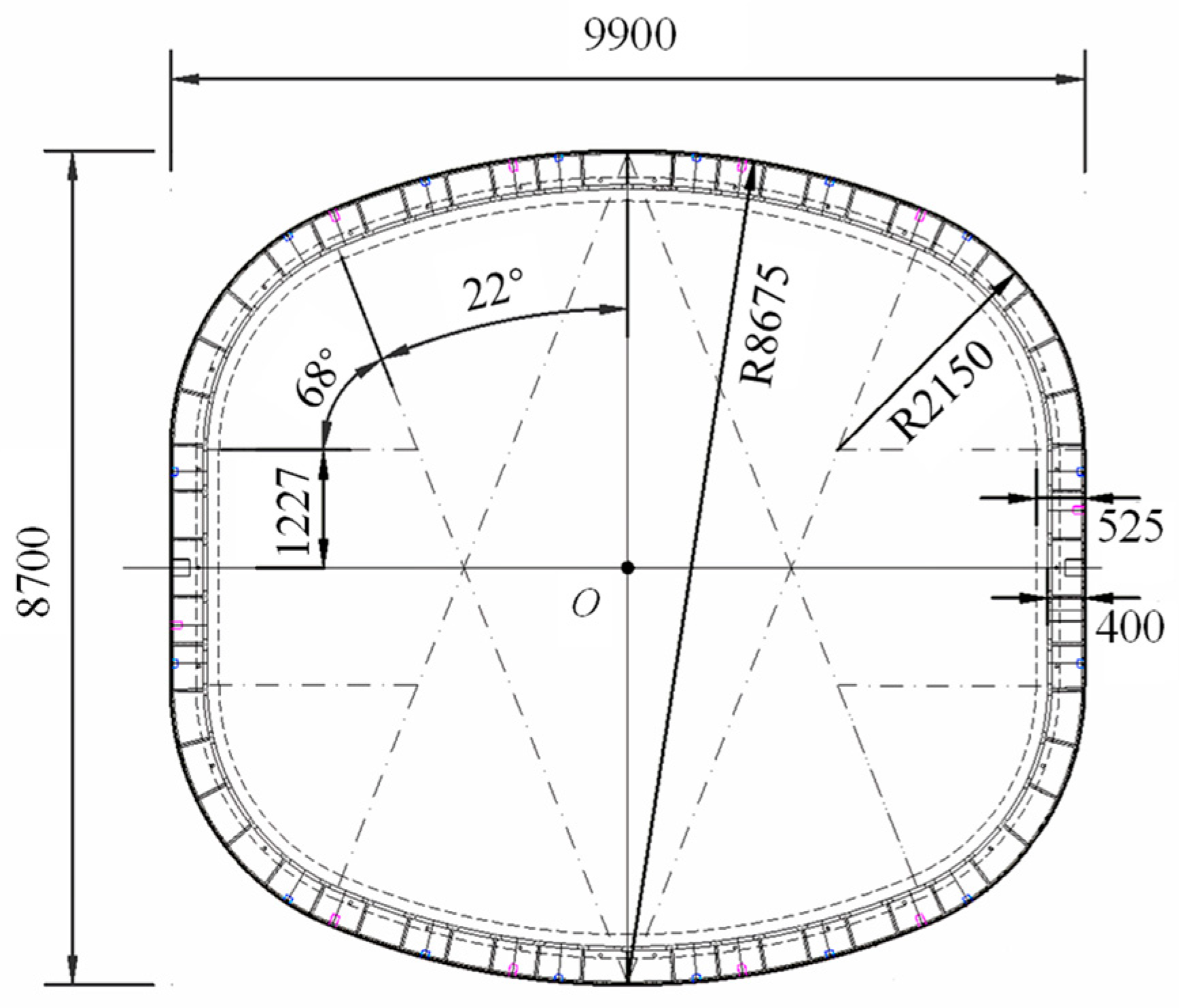
A novel type of “steel pipe section + concrete lining” composite pipe jacking is used to suit the needs of the pipe jacking method for big cross-sections and deep soil covering construction under soft soil layers. All structural steel pipe sections are utilized during transportation and construction, and when the pipe jacking has passed through, concrete is put to the interior of the pipe. Only half as heavy as a concrete pipe section (measured as a 2 m ring), a single steel pipe section weighs roughly 48 t. As depicted in Figure 2, the composite pipe jacking has an outside diameter of 9900 mm, a width of 8700 mm, and a height of 8700 mm. The wall thickness is 525 mm, of which the steel pipe section is 400 mm thick, and the concrete is 125 mm thick.
The use of “steel pipe section + concrete lining” composite pipe jacking is less common than that of typical reinforced concrete pipe and steel pipe, making it difficult for structural designers to conduct general analysis and computation. The composite pipe jacking is comparable to a single, homogeneous pipe section with an equal cross-section through the concepts of stiffness equivalence and mass equivalence, in accordance with the deformation consistency principle. The corresponding pipe section weighs 1775 kg/m3 and has a wall thickness of 455 mm.

3.2. Numerical Model and Constitutive Parameters

Shanghai is a typical natural soft ground area in the Yangtze River Delta, and the soft soil has poor engineering geological characteristics, including low strength, high water content, big pore ratio, low permeability, and apparent thixotropy and rheology. According to the geological data, the station site mainly passes through ③ mucky silty clay, ④ mucky clay, ⑤1 clay, and ⑤2 silty clay within the depth range. Since the actual soil layer is not uniformly distributed at the same depth, in order to simplify the calculation, the soil layer is weighted and averaged, i.e., the equivalent soil layer is taken and simulated by the Mohr–Coulomb model. The thickness of the grouting layer is impacted by the size of the machine head, the construction disruption, etc., and the most unfavorable circumstance is considered as 30 mm. The values of each material parameter in the finite element model are provided in Table 1.
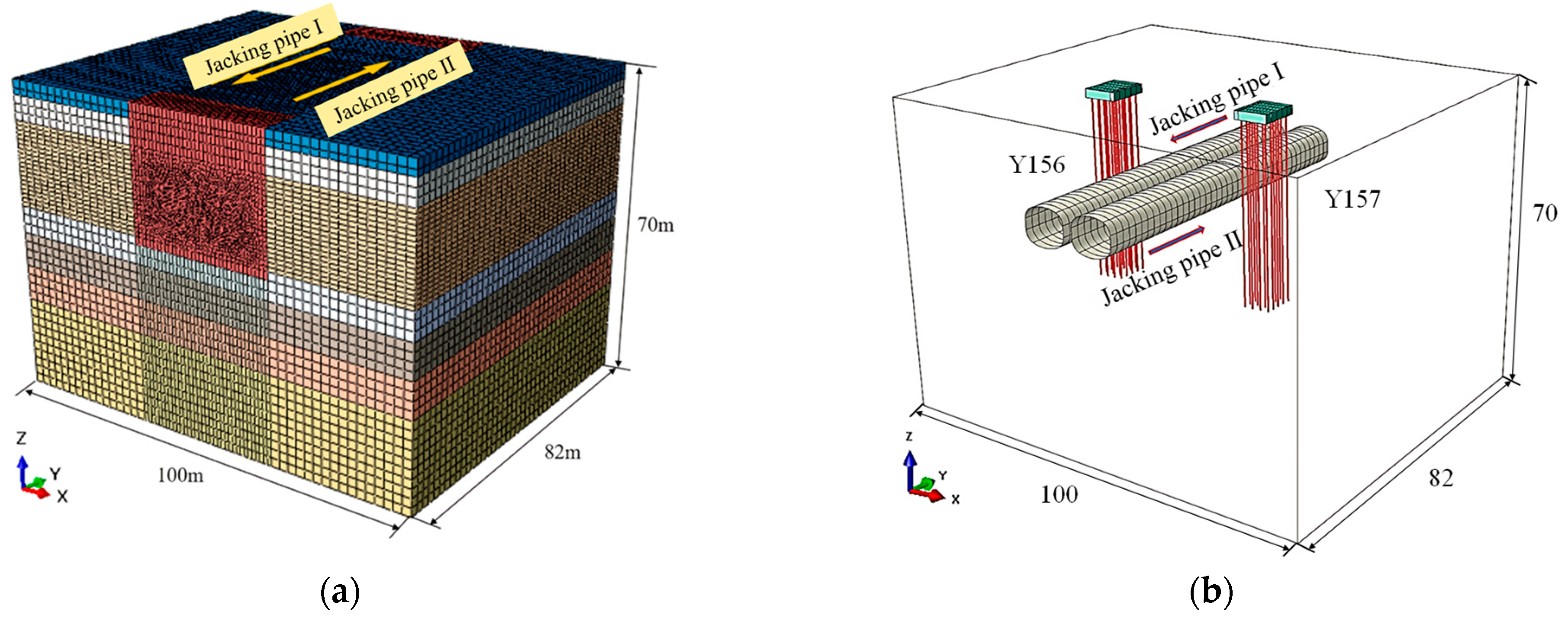
The size of the soil model is 100 m × 70 m × 82 m (X × Z × Y), and the overburden depth at the top of the pipe is assumed to be 15 m. The Z-direction displacement is fixed at the bottom, the front and back sides are fixed for the Y-direction displacement, and the left and right sides are fixed for the X-direction displacement. The model grid division is shown in Figure 3a. The model consists of two pipe jacking tunnels. Pipe jacking I’s excavation direction is along the Y-axis’s negative direction, the initial excavation surface at Y = −82 m (41 ring pipe section), and pipe jacking II’s excavation direction is along the Y-axis’s positive direction, the initial excavation surface at Y = 0 m. The horizontal distance between the two pipe jacking tunnels, which are built in parallel and then one after the other, is just about 2.05 m.
In order to ensure the safe and smooth advancement of the pipe jacking, this project uses vertical MJS construction for the reinforcement of inlet and outlet holes, and the platform level pipe jacking inlet and outlet holes have a reinforcement scope of 6 m on either side of the pipe jacking, with a reinforcement thickness of 7.5 m and a reinforcement depth of 30 m below the ground level. According to the actual scope of the reinforcement area in the project and considering the thickness of the diaphragm wall (2.2 m), the reinforcement area is cut out in the soil layer with a range of 34 m × 10 m × 30 m area.
Both the grouting layer and the equivalent pipe section are modeled by linear elasticity. A CPE4 unit is selected for both the soil body and the grouting layer, and an S4 unit is used for the shell unit model of the equivalent pipe section. There is always contact and sliding friction between the pipe jacking joint and the soil throughout the actual construction process. It is necessary to set the circumferential average friction resistance, and for the case of grouting drag reduction, the friction resistance per unit area can generally be directly assumed to be a fixed value. In this model, it is assumed that the pipe joint’s frictional resistance is equal and opposite to the driving direction. The frictional resistance is set to 3 kPa for simulation, and the grouting pressure is taken as 300 kPa with reference to the actual project.
The pipe jacking machine will pass between the Y156 and Y157 piers of the Yan’an viaduct, and the minimum clear distance between the piles of the viaduct is only about 5.6 m. The piles of Yan’an viaduct are Φ600 PHC piles with a wall thickness of 110 mm, and the length of the piles is 42 m. The C80 concrete is used. The size of the bearing platform is 8.4 m × 6.6 m and 2.0 m thick, and it is made of C25 concrete and has 18 piles. The actual bearing platform and group piles have a certain angle with the pipe jacking’s forward direction. In order to simplify the calculation, in the numerical simulation, the bearing platform and group piles are simplified to be orthogonal to the jacking direction, the minimum distance between the piles and the axis of the tunnel is taken to be 6 m, and the distance between the bearing platform and the front and rear model boundaries is 36 m. The overall model is shown in Figure 3b.
In the modeling, group pile and bearing platform models are added to the soil body, and the piles are simulated by beam unit and linear elastic models. The top of the pile is bound to the bottom of the bearing platform, and the tangential friction model of the pile foundation and soil contact surface adopts a penalty function. The friction coefficient is 0.3, and the normal direction adopts hard contact. The model parameters are shown in Table 2.

3.3. Simulation of Construction Steps

Single line pipe jacking construction is carried out initially, followed by the effects of double line pipe jacking construction and side penetration pile foundation, and finally, the following three groups of calculation conditions are established in turn. This is done in order to analyze the superimposed effects of the pipe jacking construction in close proximity and the side penetration pile foundation on the force and environment of the pipe sections. Case 1 can be utilized as a control group for the following working conditions for comparison and analysis among them because of the symmetry of the model:
Case 1: Simulation of the whole process of pipe jacking I’s gradual excavation construction.
Case 2: Simulation of the whole process of pipe jackings I and II’s construction in close proximity to each other: On the basis of the completion of pipe jacking I’s construction, a simulation of the whole process of pipe jacking II construction is carried out.
Case 3: Simulation of pipe jackings I and II crossing viaduct piles in close proximity to each other: A pile foundation model is added to the soil body, and the whole process of pipe jackings I and II’s construction is simulated successively. Since the soil layer is stable under the action of self-weight stress in history, the displacement generated by the initial stress field and viaduct construction is eliminated, and only the incremental displacement caused by subsequent pipe jacking construction is analyzed.
It should be assured that each time during the simulation, the length of the soil body being excavated will not exceed the width of one pipe segment.

4. Results Analysis

4.1. Deformation Analysis of Pipe Jacking Section

Figure 4 shows the overall internal force cloud diagram of the pipe section for Case 1. Each one-ring pipe portion before and after the model is eliminated for study because the pipe section close to the model’s boundary is where the stress concentration exists. From the bending moment diagram, it can be seen that the negative bending moment basically appeared at the top of the tube, while the positive bending moment appeared at the shoulder and foot of the arch. The 21st ring pipe section’s arch shoulder had the highest positive bending moment of the jacking pipe, which was 803.8 kN·m, and the 21st ring’s arch top had the highest negative bending moment, which was −532.4 kN·m. At the arch foot of the 22nd ring, the shear force reached its highest value of 419.2 kN. The maximum bending moment and shear moment were located in the middle of the tunnel structure, so the deformation of the pipe section in this area should be paid attention to during the tunnel construction and operation. During the construction of the pipe section, the maximum axial force is always located at the first pipe section behind the pipe jacking machine, which is due to the section influence of the jacking force and the oncoming resistance, resulting in the stress concentration in the pipe section at this location.
Figure 5 shows the cross-section bending moment of the pipe section at different positions of pipe jacking I in working condition. The pipe section bending moment is a “butterfly” type distribution, and the cross-section bending moment of the pipe section in the reinforcement area is obviously smaller than that of the pipe section in the normal advancement area, especially the negative bending moment of the top and bottom of the pipe. Because the strength of the soil around the pipe section in the reinforced area is high, the contraction trend of the surrounding soil to the pipe section direction after excavation is small, and the extrusion effect on the pipe section is small.
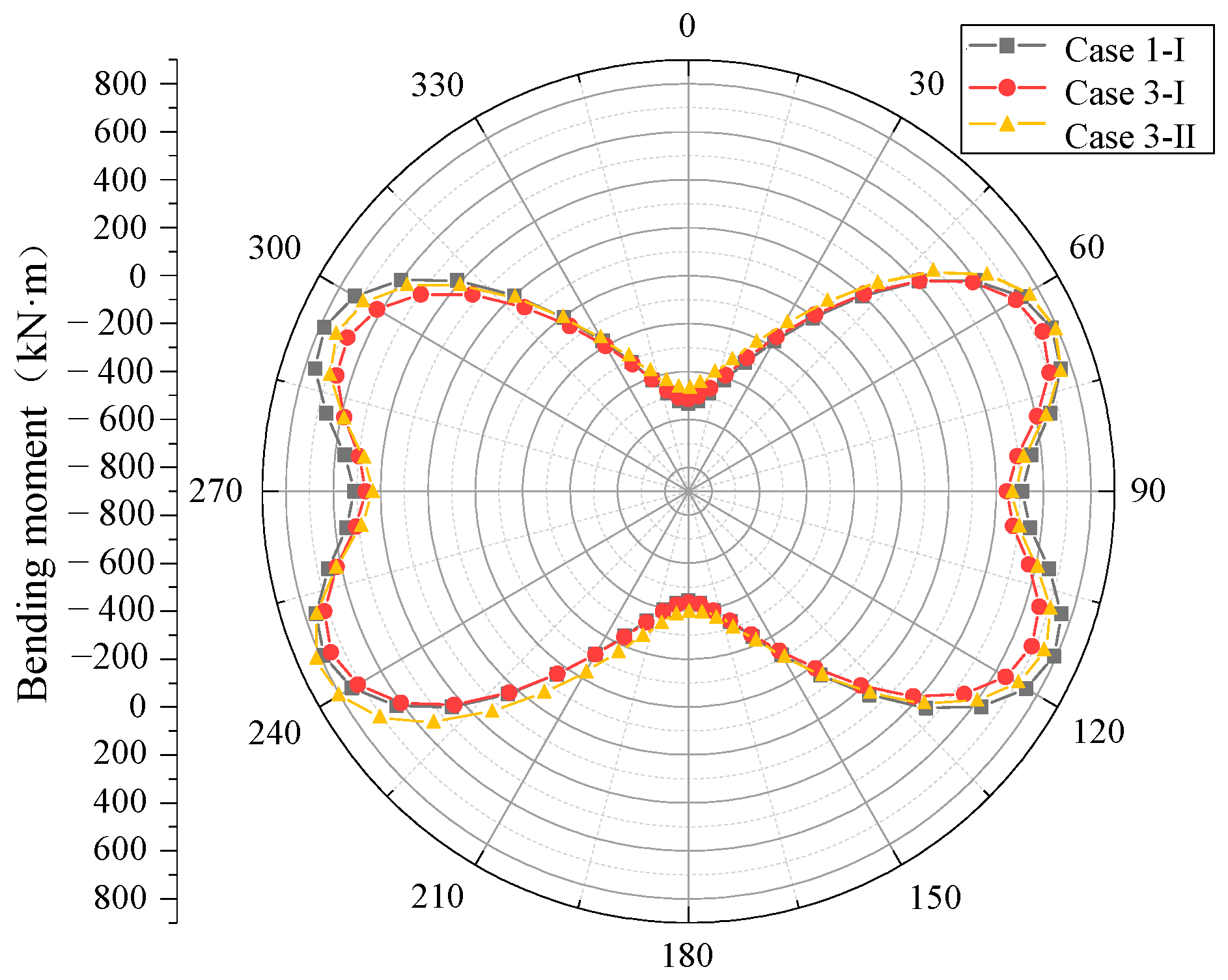
The bending moment of the 21st ring pipe segment is compared in Figure 6 for various scenarios. The pipe jacking section’s bending moment diagram still displays a “butterfly” distribution under the influence of the viaduct piles, but it is clear that the bending moment of the pipe jacking I at the left arch shoulder and the right arch foot is reduced. Additionally, the maximum positive bending moment, located in the cross-section of 246°, is reduced by 5%, and the maximum negative bending moment, located in the position of 0°, is reduced by 3%. As a result, the maximum internal force of a pipe section is reduced by the existence of a piling foundation.
The maximum positive bending moment of pipe jacking II’s pipe section increases by 3% and is located at the position of cross-section 24° due to the superimposed effect of pile foundation and pipe jacking I, and the maximum negative bending moment decreases by 14% and is located at the position of 0°. The increase in the positive bending moment in the cross-section results from the influence of pipe jacking I on pipe jacking II.
The presence of a pile foundation causes the lateral and vertical deformation of the pipe jacking section in the normal advancement zone to decrease somewhat, according to a comparison of the lateral and vertical deformation curves of the pipe section at the completion of the two pipes jacking construction in Cases 2 and 3. This is due to the fact that the pipe section enters the influence range of Yan’an’s elevated pile foundation, and the soil strength in the pile foundation area is better, which has a certain inhibiting effect on the pipe section tension deformation.
The deformation difference at each pipe section is presented in Figure 7 in order to more intuitively demonstrate the influence area of the pile foundation on pipe section deformation. The influence zone of a pile foundation on a pipe section is primarily located approximately 1D in the jacking direction behind the pile foundation, with the largest influence position being close to the pile foundation range’s outer edge. The pipe section of pipe jacking I experiences a maximum reduction in the horizontal diameter of about 5.1% and a maximum reduction in the vertical diameter of about 5.6% under the action of the piling foundation.
In order to show the influence area of the pile foundation on pipe section deformation more intuitively, the deformation difference of each position is plotted in Figure 7. The influence range of the pile foundation on the pipe section is mainly in the range of about 1D behind the pile foundation in the direction of jacking, and the maximum influence position is near the boundary of the pile foundation range. Under the influence of the pile foundation, the maximum reduction of the horizontal diameter of the pipe section of pipe jacking I is about 5.1%, and the maximum reduction of the vertical diameter is about 5.6%. The pipe section in pipe jacking II is reduced by 11% and 9.6% of horizontal and vertical diameters, respectively, compared to the pipe section in Case 1 due to the stacked influence of pile foundation and pipe jacking I.

4.2. Surface Settlement Analysis

Figure 8 shows the horizontal lateral surface settlement curve at Y = 40 m when the construction of pipe jackings I and II is completed, and this soil section is located in the range of pile foundation. It can be concluded that due to the influence of the viaduct piles and bearing platforms, the surface settlement curve of this section changes significantly, mainly in the bearing platform area, as there is a more obvious uneven settlement. The bearing platforms in pipe jackings I and II’s construction completion have vertical maximum bulge amounts of 1.0 mm and 2.6 mm, respectively. When excavating in the pipe jacking excavation area, the maximum settlement position is at the center axis of pipe jacking I, and it gradually travels to the two tunnels. The maximum settlement position gradually moves to the central axis of the two tunnels during the building of pipe jacking II. The highest settlements at the conclusion of pipe jackings I and II’s construction are 11.9 mm and 14.9 mm, respectively. The settling tank’s width also expands from 4D to 5D, with a large rise in surface uplift and settlement.
The ground surface’s longitudinal settlement curve is depicted in Figure 9 after pipe jacking II’s side penetration pile foundation is built. The surface settlement curve changes significantly near the interface between the reinforcement zone and the normal advancement zone as a result of the stronger soil in the reinforcement zone.
In the normal advancement zone, the surface settlement above pipe jacking II is smaller than that of pipe jacking I, which is due to the fact that the construction of pipe jacking I puts the soil layer above pipe jacking II in an upward uplift and then a downward settlement due to the excavation of the soil body and the loss of the ground layer in the construction of pipe jacking II. The biggest longitudinal surface settlement occurs at the axis of the two tunnels, and the maximum settlement value—14.9 mm—is found at Y = 40 m, as illustrated in the graphs.

4.3. Pile Deformation Analysis

Figure 10 shows the horizontal displacement cloud diagram of the group piles after the construction is completed. The group piles on the right side of pipe jacking I are relatively far from the excavation position when construction is complete, with a relatively small deformation value and a maximum deformation of 3.5 mm compared to the group piles on the left, which are closer to the excavation position and have a maximum value of 7.0 mm for horizontal displacement. The final horizontal displacements of the pile foundations on both sides are essentially the same after pipe jacking II construction is complete. The maximum horizontal displacements of the pile foundations on the right side are 10.9 mm, and those on the left side are 10.7 mm, showing that pipe jacking II has a greater impact on the pile foundations during construction. The lateral displacement of the pile induced by pipe jacking II is greater because the soil stiffness surrounding the pile degrades as a result of the tunnel stress release brought on by pipe jacking I’s excavation.
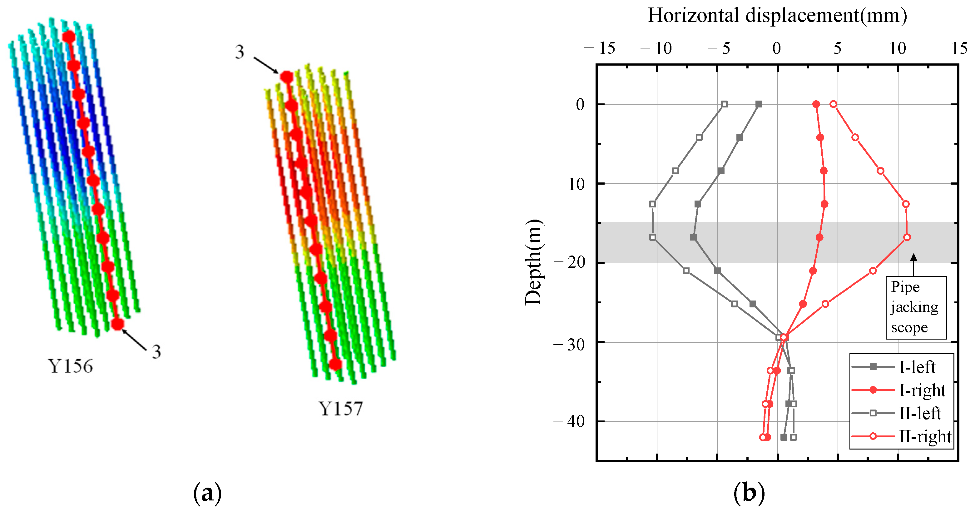
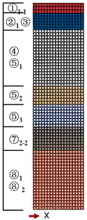
According to Figure 11, the horizontal displacement values along the depth direction (Z-axis’s negative direction) of the third pile in the left and right group piles are extracted, respectively. When pipe jacking I is finished being built, the maximum value of the pile foundation displacement on the left side is located above the pipe jacking’s range of vertical diameter, while the maximum value of the pile foundation displacement on the right side is situated within that range. Because the deformation of the pile foundation is mainly caused by the deformation of the surrounding soil layer due to the construction of the pipe jacking, the deformation of the soil body near the side wall of the pipe section is the largest. And once pipe jacking II is built, the maximum value of horizontal displacement of the pile foundation on both sides will be situated inside the pipe jacking tunnel’s range at a depth of around 17 m. Due to the fact that 28 m is the interface between the upper and lower soil layers, and the lower soil layer is more robust and difficult to disrupt, the horizontal displacement suddenly decreases at this level.

5. Monitoring Program and Results

5.1. Monitoring of Pipe Jacking Deformation

Using a Leica TM30 total station and an extremely portable Focus S 350 3D laser scanner, field measurements of the relative deformation of the pipe sections were made, with the major focus being on the cross-section deformation and longitudinal section deformation. The 3D laser scanner was selected with 10% reflectivity, and the single-point error of the instrument was less than 0.5 mm at a scanning distance of 25 m or less [21].
When entering and exiting the hole reinforcement area, entering the normal advancement area, and getting close to the viaduct piles, the pipe jacking section will exhibit various deformation characteristics. According to the development of pipe jacking II, the 25th, 26th, and 31st rings of the pipe section are chosen as the monitoring objects to conduct on-site testing in order to explore the convergence deformation law of the pipe section under various construction situations. The initial state of the pipe sections is determined to be the initial value downhole measured by a total station (rather than out of the hole), and the relative deformation of each pipe section is measured under the working conditions of entering the reinforcement zone, normal advancement zone, and close to the viaduct piles, respectively. The actual measurement schedule is shown in Table 3.
There are two methods utilized to monitor soil displacement: the surface settlement brought on by pipe jacking work and the deep lateral displacement of the earth near the bridge piles.
The downhole observed values of lateral and radial deformation are used as the initial values to explore the convergence deformation law of the pipe segment while it is progressing. The deformation values of different pipe sections used in pipe jacking II are shown in Table 4. It is evident that the pipe section’s transverse diameter gradually increases from the downhole into the reinforcement zone and then to the normal propulsion zone, and the transverse directions of the pipe sections for the 25th and 26th rings slightly change after passing under the elevated pile foundation’s influence. This agrees with the outcomes of the numerical simulation’s investigation of the pile foundation’s impact on the pipe sections.
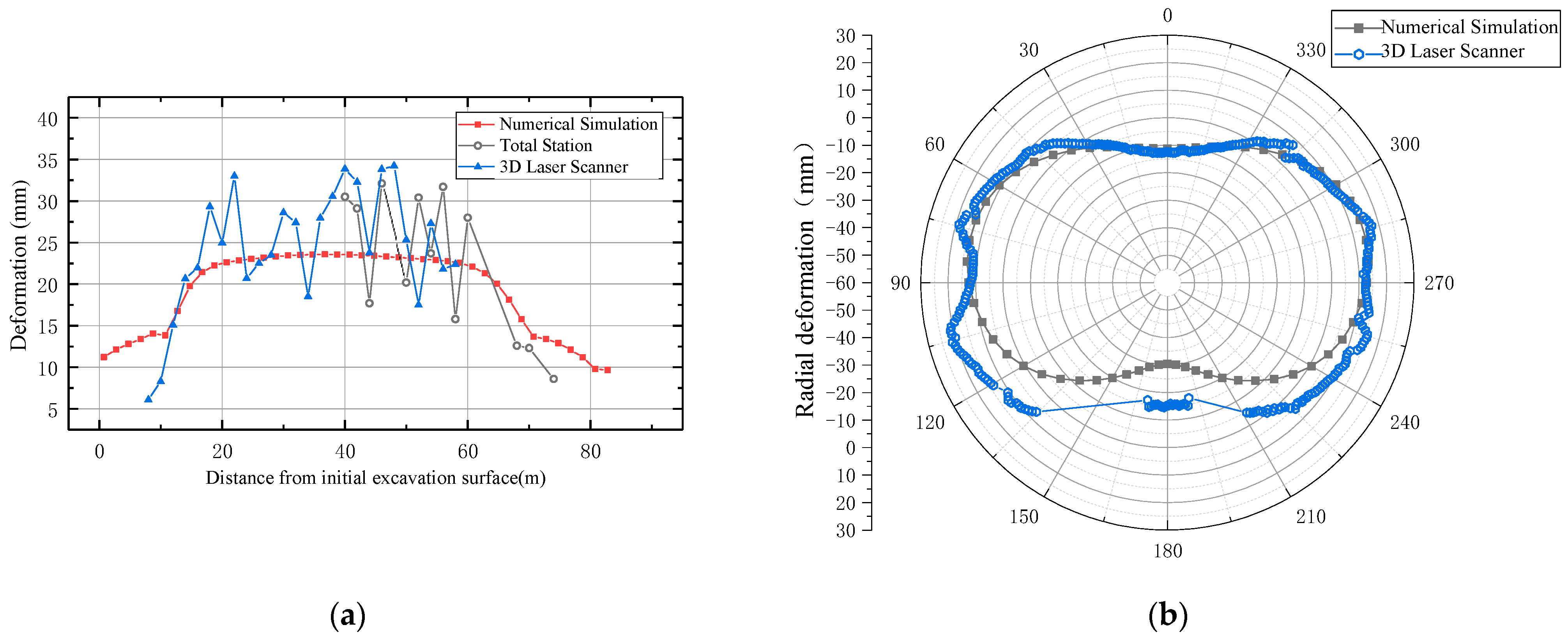
As of the completion of the building of pipe jacking I, the lateral and radial deformation curves of pipe sections along the jacking direction are compared with the outcomes of total station and 3D laser scanning, as illustrated in Figure 12. The results of the numerical simulation are essentially consistent with the measured values obtained from 3D laser scanning and the total station, and the results of the pipe section radial deformation are also largely consistent, which further verifies the applicability and accuracy of the simulation results.

5.2. Monitoring of Soil Displacement

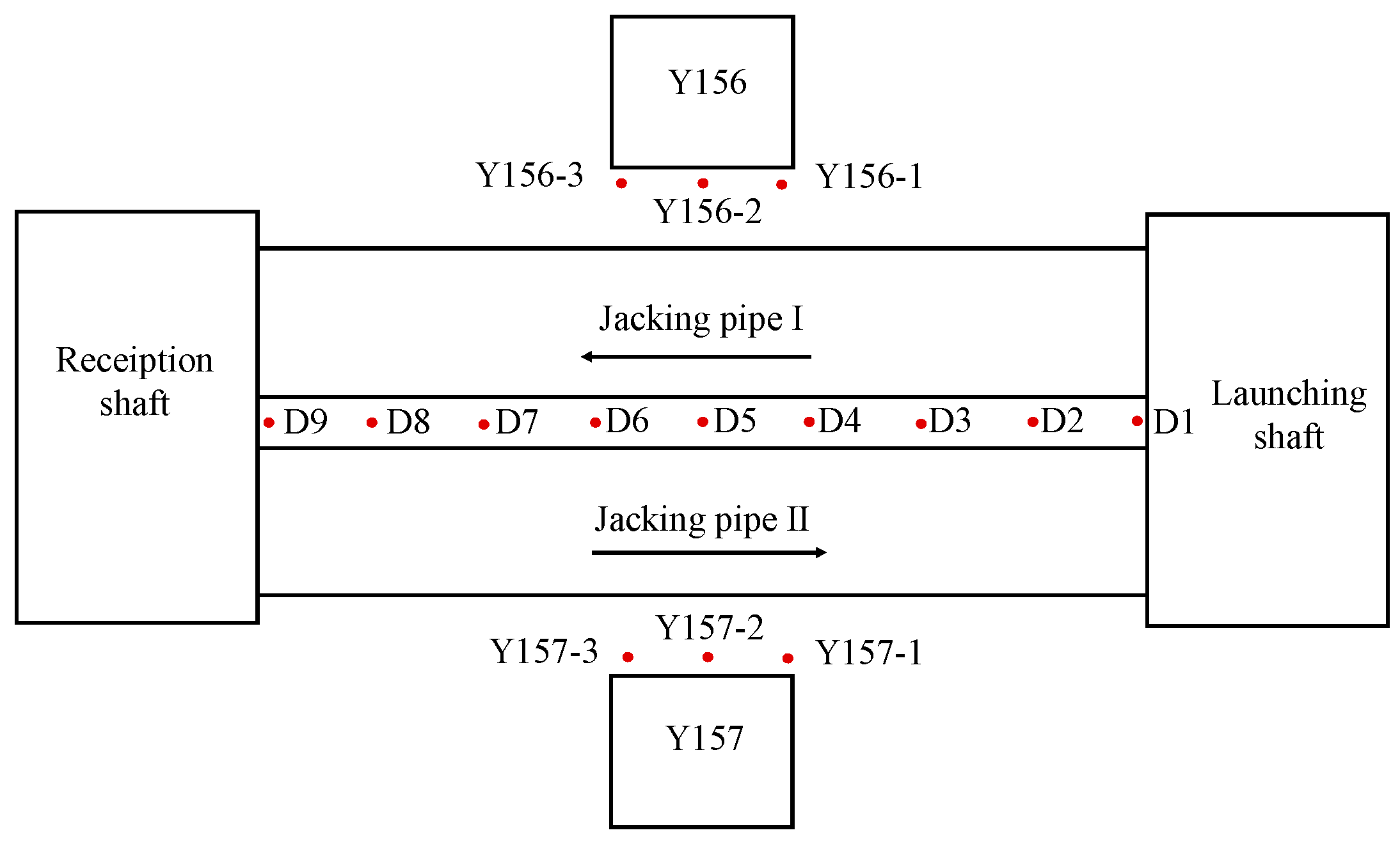
A Trimble DiNi03 electronic static level is used for the automated monitoring of the surface settlement at the center axis of the two tunnels and within a certain width on both sides. Starting from the starting shaft, nine monitoring sections are laid along the jacking direction, with a spacing of about 10 m, and the measurement points are numbered as Di, where i is the ith monitoring section, and Di (i = 1 to 9) is arranged directly above the central axis of the channel and the central axis of the two tunnels. In the distance from the viaduct abutment near the pipe jacking side of each of the three soil-deep lateral displacement monitoring holes, the hole depth longer than the abutment buried in the ground is 3 m, that is, the soil tilt hole depth is about 45 m, as shown in Figure 13.

5.2.1. Surface Subsidence Analysis

The surface deformation brought on by shield excavation can be separated into four stages based on the excavation procedure and deformation mechanism of shield construction: Stages 1 and 2’s surface deformation occurs in front of the cutter plate, the soil in front of and above the excavation is extruded and deformed by the shield’s control of soil pressure (mud and water pressure), and the surface appears to be uplifted; Stage 3 occurs when the shield passes through the excavation surface, and ground subsidence occurs due to over-excavation, deviation correction, and friction between the periphery and the surrounding soil; Stage 4 occurs after the shield passes through the excavation surface, and surface deformation is caused by soil consolidation and subsidence, which is mainly controlled by grouting.
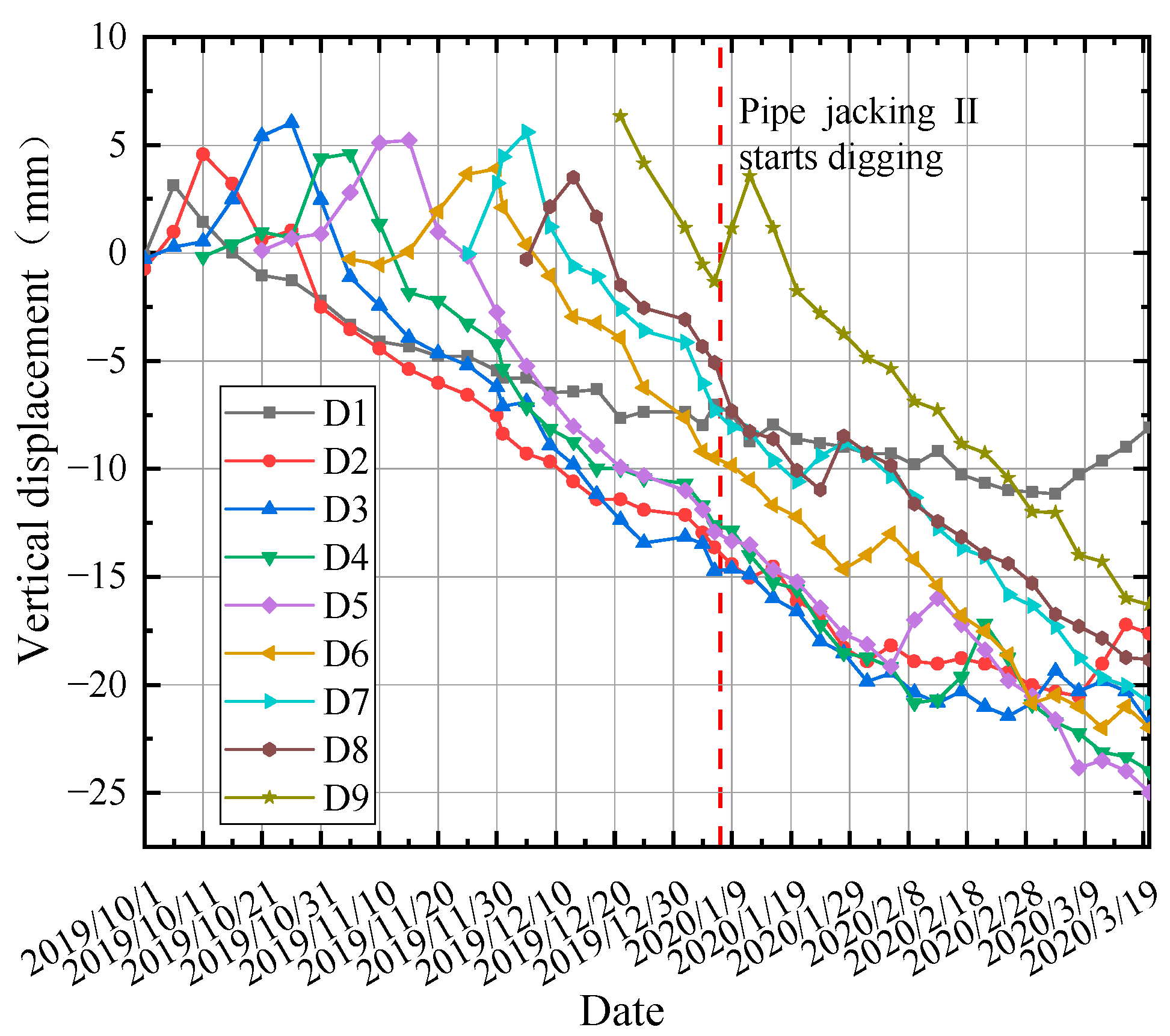
The time curve of uplifting and settlement for the measurement locations D1 to D9 is shown in Figure 14, where a positive value denotes uplifting, and a negative value denotes settlement. Each measuring point’s deformation may undergo a process of bulging and then settling. After pipe jacking I was completed on January 6, and the construction of pipe jacking II began, the curve once more displayed an uplifting trend. According to the monitoring data, the maximum ground settlement is larger than the simulation result, which may be due to the untimely filling of the gap between the back of the lining and the cave body after the shield passed through the section, resulting in the release of the ground stress and causing ground settlement.

5.2.2. Deep Lateral Displacement of Soil

The highest lateral displacement of the soil body of the bridge pile is located close to the side of the pipe section, according to the monitoring data. Figure 15 shows the soil lateral displacement over a time curve of 18 m under the bridge pier. The positive value in the figure indicates the direction away from the pipe jacking. The soil lateral displacement of 20 m under the bridge pier increases with the advancement of the pipe jacking; Y156 is close to the pipe jacking I, and the soil displacement grows faster in comparison to the bridge piles on the right side.
After the completion of pipe jacking I, the maximum horizontal displacements of the soil body of the soil on the left and right pile sides are 9.5 mm and 6.6 mm, respectively. After pipe jacking II begins to dig, the displacement of the soil body of Y156 on the right side rises more quickly. The maximum horizontal displacements of the soil 20 mm under the piles on both sides are 15.7 mm and 17.4 mm, respectively, and the construction of the pipe jacking II has a greater influence, which is consistent with the simulation results. After construction is complete, the final horizontal displacements of the piles on both sides are essentially the same.

6. Conclusions

Combined with the actual project, this paper simulates the construction process of large cross-section quasi-rectangular pipe jacking by a numerical simulation method, verifies it with the monitoring data, and obtains the following conclusions:
(1) The viaduct piles have a noticeable reducing effect on the maximum positive and negative bending moments as well as the bending moments at the left arch shoulder and right arch foot of the pipe section. Additionally, the pile foundation has a certain inhibiting effect on the lateral and vertical deformation of the pipe section of the jacking tube.
(2) The lateral surface settlement curve in the middle of the tunnel is significantly altered by the influence of viaduct piles and bearing platforms. Additionally, as the two pipe jackings successively pass through the pile foundations at close intervals, the maximum lateral surface settlement gradually shifts from the location of the central axis of pipe jacking I to the vicinity of the two tunnels’ central axes.
(3) The tunnel stress release caused by the excavation of pipe jacking I leads to the degradation of soil stiffness around the pile body, so the lateral movement of the pile caused by pipe jacking II is greater. The maximum horizontal displacement of the pile foundation is located at an underground depth of about 17 m within the jacking tunnel.

Author Contributions

Study conception and design: Y.Y. and M.Z.; Data collection: Y.Y. and M.C.; Analysis and interpretation of results: Y.Y.; Drafting of the manuscript: Y.Y. All authors have read and agreed to the published version of the manuscript.

Funding

This work is supported by financial support from the National Natural Science Foundation of China (No. 52078286). The support above is gratefully acknowledged.

Institutional Review Board Statement

Not applicable.

Informed Consent Statement

Not applicable.

Data Availability Statement

The data that support the findings of this study are available on request from the correspond ding author. The data are not publicly available due to privacy restriction.

Acknowledgments

The authors wish to special thank Zhang Mengxi for their careful guidance as a supervisor during their studying period at Shanghai University.

Conflicts of Interest

The authors declare no conflict of interest.

References

  1. Sterling, R.L. Developments and Research Directions in Pipe Jacking and Microtunneling. Undergr. Space 2018, 5, 1–19. [Google Scholar] [CrossRef]
  2. Jianbin, L. Key Technologies and Applications of the Design and Manufacturing of Non-Circular TBMs. Engineering 2017, 3, 905–914. [Google Scholar]
  3. Chen, X.; Ma, B.; Najafi, M.; Zhang, P. Long rectangular box jacking project: A case study. Undergr. Space 2019, 6, 101–125. [Google Scholar] [CrossRef]
  4. Shimada, H.; Khazaei, S.; Matsui, K. Small diameter tunnel excavation method using slurry pipe-jacking. Geotech. Geol. Eng. 2004, 22, 161–186. [Google Scholar] [CrossRef]
  5. Sun, J. Research on environmental soil engineering works during underground construction activities in ubran area. Undergrourd Eng. Tunmels 1999, 3, 2–6. [Google Scholar]
  6. Lu, A.Z.; Xu, G.S.; Sun, F.; Sun, W.Q. Elasto-plastic analysis of a circular tunnel including the effect of the axial in situ stress. Int. J. Rock Mech. Min. Sci. 2010, 1, 50–59. [Google Scholar] [CrossRef]
  7. Dafalla, M.; Aldeghaither, S.; Taha, N.; Al-Laham, M.; Al-Zoubi, L. Efficient Pile Distribution for Piled-Raft Foundations for Tall Buildings. In Geo-Congress 2020; 1st Session on Foundations, Soil Improvement, and Erosion at Geo-Congress on Vision, Insight, Outlook; American Society of Civil Engineers: Reston, VA, USA, 2020; Volume 315, pp. 246–255. [Google Scholar]
  8. Zhou, S.; Wang, Y.; Huang, X. Experimental study on the effect of injecting slurry inside a jacking pipe tunnel in silt stratum. Tunn. Undergr. Space Technol. 2009, 24, 466–471. [Google Scholar] [CrossRef]
  9. Shou, K.; Yen, J.; Liu, M. On the frictional property of lubricants and its impact on jacking force and soil-pipe interaction of pipe-jacking. Tunn. Undergr. Space Technol. 2010, 25, 469–477. [Google Scholar] [CrossRef]
  10. Soomro, M.A.; Kumar, M.; Xiong, H.; Mangnejo, D.A.; Mangi, N. Investigation of effects of different construction sequences on settlement and load transfer mechanism of single pile due to twin stacked tunnelling. Tunn. Undergr. Space Technol. Inc. Trenchless Technol. Res. 2020, 96, 103171. [Google Scholar] [CrossRef]
  11. Peck, R.B. Deep excavations and tunneling in soft ground. In Proceedings of the 7th International Conference on Soil Mechanics and Foundation Engineering; Sociedad Mexicana de Mecanica: Mexico City, Mexico, 1969; pp. 147–150. [Google Scholar]
  12. Yang, X.; Li, Y.S. Research of surface settlement for a single arch long-span subway station using the Pipe-roof Pre-construction Method. Tunn. Undergr. Space Technol. Inc. Trenchless Technol. Res. 2018, 72, 210–217. [Google Scholar] [CrossRef]
  13. Li, R.; Lei, H.; Liu, Y.; Zhang, Y.; Hu, Y. Ground Movement and Existing Tunnel Deformation Induced by Overlapped Tunneling. Int. J. Geomech. 2022, 22, 04022098. [Google Scholar] [CrossRef]
  14. Wang, Y.Z.; Zhang, D.L.; Fang, Q.; Liu, X.; Wang, J.C. Analytical Solution on Ground Deformation Caused by Parallel Construction of Rectangular Pipe Jacking. Appl. Sci. 2022, 12, 3298. [Google Scholar] [CrossRef]
  15. Ma, W.; Wang, B.; Wang, X.; Zhou, S.; Wang, B. Soil Layer Disturbance Caused by Pipe Jacking: Measurement and Simulation of a Case Study. KSCE J. Civ. Eng. 2021, 25, 1467–1478. [Google Scholar] [CrossRef]
  16. Zhang, X.; Jiang, Y.; Cai, Y.; Li, X.; Golsanami, N.; Wang, X.; Hao, J.; Li, N.; Wu, F.; Wang, X. A Simplified Method for Predicting Tunneling-Induced Ground Movement considering Nonuniform Deformation Boundary. Shock Vib. 2022, 2022, 6289303. [Google Scholar] [CrossRef]
  17. Sheil, B.B.; Suryasentana, S.K.; Templeman, J.O.; Phillips, B.M.; Cheng, W.C.; Zhang, L. Prediction of Pipe-Jacking Forces Using a Bayesian Updating Approach. J. Geotech. Geoenvironmental Eng. 2021, 148, 04021173. [Google Scholar] [CrossRef]
  18. Ma, P.; Shimada, H.; Sasaoka, T.; Hamanaka, A.; Moses, D.N.; Dintwe, T.K.; Matsumoto, F.; Ma, B.; Huang, S. A new method for predicting the friction resistance in rectangular pipe-jacking. Tunn. Undergr. Space Technol. 2022, 123, 104–338. [Google Scholar] [CrossRef]
  19. Wen, K.; Shimada, H.; Zeng, W.; Sasaoka, T.; Qian, D.Y. Frictional analysis of pipe-slurry-soil interaction and jacking force prediction of rectangular pipe jacking. Eur. J. Environ. Civ. Enginecring 2020, 24, 814. [Google Scholar] [CrossRef]
  20. Pan, Z.; Du, K.; Lv, F.; Tao, S. Numerical Simulation of Mechanical Response of Bridge Foundation and Existing Tunnel Caused by Pipe Jacking Construction. J. Phys. Conf. Ser. 2022, 2230, 012008. [Google Scholar] [CrossRef]
  21. Soudarissanane, S.; Lindenbergh, R.; Menenti, M.; Teunissen, P. Scanning geometry: Influencing factor on the quality of terrestrial laser scanning points. ISPRS J. Photogramm. Remote Sens. 2011, 66, 389–399. [Google Scholar] [CrossRef]
Figure 1. Cross-sectional diagram of pipe jacking construction section (unit: mm).
Applsci 13 09799 g001
Figure 2. Quasi-rectangular jacking pipe section size (unit: mm).
Applsci 13 09799 g002
Figure 3. Finite element model. (a) the model grid division, (b) group pile and bearing platform model.
Applsci 13 09799 g003
Figure 4. Overall internal force cloud diagram of pipe section of pipe jacking I. (a) bending moment diagram (kN·m), (b) shear diagram (kN).
Applsci 13 09799 g004
Figure 5. Cross-sectional bending moment diagram of different pipe sections of pipe jacking I.
Applsci 13 09799 g005
Figure 6. The cross-sectional bending moment of 21 ring pipe sections under different cases.
Applsci 13 09799 g006
Figure 7. Differential deformation of pipe section under different cases.
Applsci 13 09799 g007
Figure 8. Lateral surface settlement when pipe is completed (Y = 40 m).
Applsci 13 09799 g008
Figure 9. Longitudinal surface settlement when pipe jacking is completed.
Applsci 13 09799 g009
Figure 10. Horizontal displacement of pile foundation. (a) pipe jacking I, (b) pipe jacking II.
Applsci 13 09799 g010
Figure 11. Horizontal displacement of pile foundation when pipe jacking is completed. (a) schematic diagram of pile foundation, (b) variation of horizontal displacement of pile foundation with depth.
Applsci 13 09799 g011
Figure 12. Comparison and verification of numerical simulation and measured results. (a) comparison and verification of numerical simulation and measured results, (b) radial deformation of pipe section.
Applsci 13 09799 g012
Figure 13. Monitoring point layout drawing.
Applsci 13 09799 g013
Figure 14. Settlement-time curves of monitoring points.
Applsci 13 09799 g014
Figure 15. Settlement-time curves of monitoring points.
Applsci 13 09799 g015
Table 1. Basic parameters of soil in the finite element model.
Soil Layer The Name of the SoilThickness (m)Density (kg/m3)Cohesion (kPa)Angle of Internal Friction (°)Modulus of Elasticity (MPa)Poisson’s Ratio
11-1 miscellaneous fill3.419009.015.00100.33Applsci 13 09799 i001
21 clay5.6180513.415.0614.40.33
③mucky silty clay
3④mucky clay19.2180316.113.9938.40.35
1 clay
42 silty clay+ silt6.1188013.024.5079.50.31
53 silty clay7.7188723.421.0892.50.31
62-2 silt7.919906.033.632140.26
71 clay20.1186324.418.40800.33
2 silty clay+ silt
The grouting layer/0.031200//1.50.45
Table 2. Basic parameters of soil in the finite element model.
StructureModulus of Elasticity
(GPa)
Poisson’s
Ratio
Density
(kg/m3)
Sizes
Pile380.32500Φ600 mm × 42 m
bearing platform280.225008.4 m × 6.6 m × 2 m
Table 3. Measurement progress meter.
DateThe 25th RingThe 26th RingThe 31st Ring
25 January 2020The reinforcement area (4 m)The reinforcement area (2 m)
5 February 2020The normal advancement area (16 m)The normal advancement area (14 m)The reinforcement area (4 m)
18 February 2020The normal advancement area (34 m)The normal advancement area (32 m)The normal advancement area (22 m)
Note: Distance from the opening in the starting shaft in parentheses, i.e., the advancement distance of the pipe section.
Table 4. Transverse opening of different pipe sections (unit: mm).
Serial
Number
Starting Value25 January 20205 February 202018 February 2020Cumulative Deformation
The 25th ring9307.6+19.9+5.7−4.8+20.8
The 26th ring9329.7+6.1+8.5−1.0+13.6
The 31st ring9327.5/+3.3+2.5+5.8
Disclaimer/Publisher’s Note: The statements, opinions and data contained in all publications are solely those of the individual author(s) and contributor(s) and not of MDPI and/or the editor(s). MDPI and/or the editor(s) disclaim responsibility for any injury to people or property resulting from any ideas, methods, instructions or products referred to in the content.