Featured Application
The application of this work in the optimization design direction of large-scale wind turbine blade airfoils and can provide a technical reference for the optimization design of other aircraft airfoils.
Abstract
Combined with the cuckoo search algorithm (CSA) and the Kutta–Joukowski (KJ) theorem, a CSA-KJ optimization method was proposed to improve the airfoil aerodynamic characteristics in this work. The fourth-order constant-free polynomial function was employed to describe the airfoil profile. The KJ loop lift of the airfoil was taken as the objective function, and the CSA was applied to iteratively update this method, which was used to optimize the NACA4412 airfoil. The results demonstrate that the optimized effect of the CSA-KJ method on the lift-drag ratio becomes increasingly more significant with the increase of incoming wind speed, and it has the best performance at an angle of attack of 0°. Compared with the NACA4412 airfoil, the average and the maximum lift-drag ratio coefficients of the CSA-KJ4412 airfoil have increased. Meanwhile, the pressure difference distribution is improved, and the aerodynamic characteristic is better. From this, it can be seen that the CSA-KJ method can provide an effective way to optimize the aerodynamic performance of other airfoils.
1. Introduction
Wind energy is an important clean and renewable energy source. The design of wind turbines is an important aspect of wind energy utilization. One of the most critical components of wind turbines is the blade airfoil, as its design directly affects the power generation efficiency of wind turbines. However, with the increasing complexity of wind turbine operating conditions, the existing wind turbine blade airfoils cannot adapt to offshore conditions, which leads to the problem of low power generation efficiency of wind farms.
The reliability of a wind turbine depends on the careful design of its airfoil structure so that it can absorb energy with great efficiency, which plays a crucial role in the wind energy conversion system [1]. The lift-drag ratio coefficient of an airfoil is important to both the aircraft and wind turbines, and a high lift-drag ratio contributes to efficient energy conversion. The NACA5505 airfoil used by Gui et al. [2] has a higher lift drag ratio and thrust coefficient than other airfoils, and the wind turbine has higher wind energy conversion and output power under low Reynolds number conditions, providing effective power generation. Chitransh et al. [3] proposed design standards for different types of NACA family airfoils for wind turbine blades and performed airfoil performance analysis using different possible values of the angle of attack. To achieve a high lift-drag ratio, it is necessary to enhance the lift of the airfoil, and the airfoil profile is the most important factor affecting the lift. Therefore, optimizing the airfoil profile is necessary to improve its lift-drag ratio.
The Kutta–Joukowski (KJ) lift theorem is the most important theory of airfoil lift [4]. Spall et al. [5] used Kutta Joukowski’s theorem to calculate the lift in order to study the specific application of aerodynamics. Gutierrez et al. [6] estimated the quasi-steady lift at mid-downstroke based on the velocity field by applying the theorem. Meanwhile, Wang, He, and Liu [7] proposed a Wake-Sectional Kutta–Joukowski (WS-KJ) model and predicted the time-averaged lift by considering the spatial evolutionary effects of the complex vortex structures in the wake. This has significantly improved the prediction accuracy of the time-averaged lift. In another instance, van Veen, van Leeuwen, and Muijres [8] combined the forward stroke motion of the wing with the rapid pitching motion and used the Kutta–Joukowski theorem to build the mathematical model of rotational force mechanisms. Zhuang et al. [9] established the hydraulic unbalance force model of the hydro-generator blades based on the KJ theorem. From these experiments, it can be seen that the KJ theorem has been widely applied in the calculation of airfoil lift and has a good application background.
In terms of the selection of airfoil optimization tools, the Genetic Algorithm (GA) [10,11,12] and Particle Swarm Optimization Algorithm (PSOA) [13,14] were used by many scholars. However, the classical swarm intelligence algorithms represented by the GA and PSOA still have certain deficiencies in optimization performance, which can lead to poor airfoil optimization results. De Tavernier [10] used the GA to optimize the airfoil shape considering a balance between the aerodynamic and structural performance of airfoils, but it was found it converged, in the region of interest, after 30 generations. Akram et al. [11] optimized the lower and upper bound of airfoil profile values through GA MATLAB code, and the results showed that the optimized effect of airfoil profile (NREL S-821) by the GA was not obvious compared with the original airfoil shape. In order to obtain the optimal lift and drag coefficients, Farhadi et al. [12] applied GA to optimize airfoil parameters, but the algorithm converged only after 15 generations; it can be seen that the premature convergence of GA has a limited effect on the improvement of airfoil performance. Kotinis [14] utilized the PSOA without considering robustness to optimize the shape of the transonic airfoil; however, the results may be affected by data disturbance and noise in the model. Compared with GA and PSOA, Cuckoo Search Algorithm (CSA) not only has higher search efficiency [15] but also better convergence and global search ability [16]. Moreover, the accuracy, stability and parameter optimization of CSA are better than those of GA and PSOA [17,18]. It should be noted that CSA has been widely utilized in airfoil optimization and has obtained good results [19,20]. Therefore, CSA was applied to optimize the airfoil profile in order to identify the airfoil with better aerodynamic characteristics in this study.
The Spalart allmaras (SA) turbulence model has been widely used in airfoil aerodynamic analysis [21,22,23,24]. Pellerin, Leclaire, and Reggio [25] proposed a turbulence model to analyze the airfoil flow field based on the lattice Boltzmann method and compared it with the results of the SA turbulence model. Rogowski, Hansen, and Bangga [26] applied the computational fluid dynamics FLOWer code to verify the shear stress transport (SST) turbulence model. The corresponding lift and drag coefficients were obtained with the aid of the steady-state calculation on the applied airfoil. Sanei and Razaghi [27] verified that the , SA and the transition SST model had high accuracy when the Reynolds number and the angle of attack were significant (i.e., above 10–12°). Wang, and Zhao [28] used the SA turbulence model to assess the accuracy of the unsteady aerodynamic characteristics of the SC1095 airfoil under free flow velocity/pitch oscillation coupling. From these studies, it can be concluded that the SA turbulence model has a high-level accuracy, so it can be effectively used to analyze airfoil aerodynamic characteristics.
In summary, while the KJ theorem has made some progress in calculating airfoil lift, and CSA has a significant impact on airfoil optimization, few studies have combined the two in their optimization efforts. In view of this, the CSA-KJ aerodynamic optimization method is achieved in this work by taking KJ airfoil as the objective function and CSA as the iterative updating tool, applied to the NACA4412 airfoil. The airfoil aerodynamic characteristics are then calculated and analyzed using the SA turbulence model, providing an effective method for optimizing the aerodynamic performance of other airfoils.
2. Aerodynamic Optimization Method: CSA-KJ
2.1. Objective Function of CSA-KJ Method
Assume that the flow field around the airfoil is uniform, inviscid, incompressible and without turbulence, the circulation lift of the object in the inviscid flow field is calculated according to the KJ theorem as [29]
where is the fluid velocity at infinity, m·s−1. is the density, kg·m−3. is the path integral of fluid velocity along a closed curve, which is the closed curve integral of airfoil surface velocity along the path of the airfoil profile, and it can be expressed as
in which, is the average fluid velocity per unit length of the airfoil profile. According to the differential method, can be written as
where and are the unit lengths in the direction of the -axis and -axis, respectively.
For the sake of obtaining the fluid velocity on the airfoil profile surface, a fourth-order constant-free polynomial function is used to describe the upper and lower profiles of the airfoil, and it can be expressed as
where are the polynomial coefficients, which can be obtained by the least square method.
It is assumed that the radius of the two-dimensional flow tube where the airfoil is located is , and its fluid flow is a laminar one. According to fluid continuity, when the fluid velocity entering the flow field is , the fluid velocity at the chord length of the airfoil profile can be defined as
Substituting Equations (3) and (5) into Equation (2), one can express the airfoil circulation as follows
then combined Equation (1) with Equation (6), the calculation formula of airfoil lift is written as
consequently, the objective function of the CSA-KJ aerodynamic optimization method is obtained.
2.2. Airfoil Optimization Process of CSA-KJ Method
CSA is a widely used natural heuristic algorithm, and the cuckoo search (CS) algorithm in the following three ideal states:
- (1)
- Each cuckoo lays only one egg at a time, and randomly selects a nest for storage.
- (2)
- During the process of nest hunting, the nest with the best eggs will be preserved for the next generation.
- (3)
- The number of available nests is fixed, and the probability of finding foreign eggs in a nest is , [0,1]. If foreign birds’ eggs are found, the owner of the nest will build a new nest.
The updated CSA formula can be written as [30]
where and are the individuals before and after updating, respectively, is the selected individual whose matrix consists of 0 and 1 elements, and is the difference between any two individual matrices in the group.
The coordinate points constituting the airfoil are regarded as the individuals of the population in CSA, the updated Equation (8) is employed to renew individuals iteratively. According to the process of cuckoo hatching eggs, the airfoil optimization process using CSA is described as follows:
- Step 1:
- Define objective function , and select in Equation (7) as the objective function of CSA-KJ aerodynamic optimization method.
- Step 2:
- Use the NACA4412 airfoil as the object of comparison in function initialization stage of this work and obtain coordinate points, respectively, on the upper and lower profile line of NACA4412 airfoil and fit the coordinate points at the upper and lower lines of the airfoil with fourth-order nonconstant polynomial function. Obtain two fitting curves and set 200 initial positions randomly on the fitting curve.
- Step 3:
- Set population size, dimension of problem and maximum number of iterations. In this work, population size n is 200. Problem dimension is 2, here . Upper limit of optimization iteration set to .
- Step 4:
- Generate or update the position of each individual in the group.
- Step 5:
- Calculate the objective function value of each nest position, and then obtain the current optimal function value according to Equation (7).
- Step 6:
- Record the value of the last generation optimal function and update the position and status of other bird nests with Equation (8).
- Step 7:
- Compare the current position function value with the previous generation optimal function value. If it is better, change the current optimal value.
- Step 8:
- Gain the processed airfoil when the calculated airfoil lift is greater than the set maximum lift or the number of iterations is greater than, otherwise, continue to return the Step 4.
- Step 9:
- Obtain the maximum lift and the coordinate point corresponding to the maximum lift and use the fourth-order non-constant function to fit the parameters of the upper and lower airfoil coordinate points. Finally, generate the smooth airfoil and establish the aerodynamic analysis model of the airfoil.
After fitting the coordinate points at the upper and lower profile lines of the airfoil with the fourth-order constant-free polynomial function, the coefficient values of Equation (4) are obtained, as shown in Table 1.

Table 1.
Fourth-order constant-free polynomial coefficient values.
To better observe the optimization flow path, the specific flow chart of the CSA-KJ airfoil optimization method is shown in Figure 1.
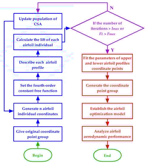
Figure 1.
Flow chart of CSA-KJ airfoil optimization method.
3. Example Analysis and Simulation
3.1. NACA4412 Airfoil Optimization and Grid Division
To test the effectiveness of the CSA-KJ airfoil optimization method, we optimize the zero angle of attack of the NACA4412 airfoil in this work, and the parameters are set as follows: is the upper limit of optimization iteration, is the target lift, is the incoming flow velocity, is the angle of attack, is the fluid density, and is the radius of the flow tube. The CSA-KJ4412 airfoil is obtained through an iterative calculation process using the CSA-KJ method. As shown in Figure 2, the shape of the airfoil before and after treatment is displayed. It is evident that the profile of the CSA-KJ4412 airfoil exhibits good smoothness, indicating that the airfoil profile is effectively described by a fourth-order constant-free polynomial function.
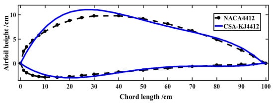
Figure 2.
Airfoil shape before and after treatment.
3.2. CFD Simulations
The density of the grid significantly affects the precision of the calculation. In order to obtain accurate results, the absolute relative error of the lift force of the CSA-KJ4412 airfoil is taken as the standard for selecting the optimal grid number. In this study, grid independence verification is also carried out.
The accuracy of the CFD model is verified by calculating the lift and drag of the airfoil. The calculation formulas of the lift and drag are as follows
where is the lift coefficient, is the drag coefficient, and is the fluid density.
In grid independence verification and subsequent simulation, determine SA as the turbulence model and set the boundary condition of the semicircular grid as the velocity inlet, the upper and lower boundaries of the rectangle as the wall, and the right boundary condition as free outflow. Select the air as fluid, and set its temperature as 298.15 K, its viscosity as kg/(m·s), and its density as 1.225 kg/m3. The iterative residual threshold is given as , and the maximum number of iterations is . The incompressible URANS equation is solved by the computational fluid dynamics software Fluent 19.2. The SIMPLEC algorithm is applied to the coupling solution of pressure and velocity. The second-order upwind scheme is set as for the convection term, the second-order central difference scheme is selected as the diffusion term, and the central difference scheme is applied to the pressure term and viscous flux. The verification results of lift force under different grid numbers are listed in Table 2.
Table 2.
Absolute relative error of lift force.
It can be observed from Table 2 that the lift force difference between Grid 3 and Grid 4 is less than 1% when the number of grids is increased by about 30–50%. Due to the smaller grid number, Grid 4 is used to calculate the airfoil aerodynamic characteristics.
The airfoil chord length and the radius of the semicircular flow field are separately set to 1 m and , the grid area of the flow field on the right is , and the number of grids on the airfoil surface is selected as 140. The grid height of the first layer is , value is approximately equal to 1. The flow field on the right is divided into upper and lower parts and symmetrical to the -axis, the upper and lower ends are both divided into 24 segments, and the height is separated into 48 segments, so the total number of grids in the calculation domain is 9024. The generated mesh is presented in Figure 3.
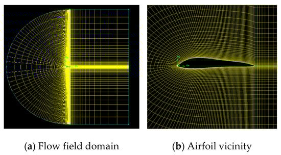
Figure 3.
Generated mesh of CSA-KJ4412 airfoil.
3.3. Reliability Verification of CSA-KJ Method
In order to confirm the validity of the numerical calculation, the NACA4412 airfoil was taken as an example to compare the numerical calculation results by CFD with the experimental data [31]. The lift coefficient of the NACA4412 airfoil at a Reynolds number of in the steady state, is shown in Figure 4. In terms of the lift coefficient, the curve trend obtained by numerical calculation is consistent with the experimental data, and the numerical calculation results are closer to the experimental value; especially if the angle of attack is −2°. In general, the results show that the numerical calculation results by CFD are accurate and agree well with the experimental data. The following numerical calculations for the airfoil in this study were performed using the same method mentioned above.
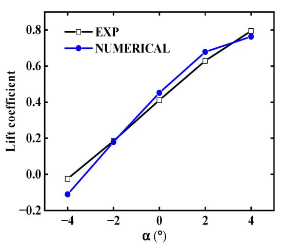
Figure 4.
Comparison of numerical calculation values and experimental values.
Cai, Xie, and Zhang [32] obtained the NEW4412 airfoil by optimizing the design of the NACA4412 airfoil, while the CSA-KJ4412 airfoil was obtained through the CSA-KJ optimization algorithm in this work. In order to highlight the lift coefficient of the optimized CSA-KJ airfoil in this study, the curves of lift coefficient (CL) of CSA-KJ4412, NEW4412 and NACA4412 airfoils are plotted in Figure 5. It is not difficult to find that when the Reynolds number is and the attack angle is in the range of −4° to 4°, the lift coefficients of CSA-KJ4412 and NEW4412 are both higher than those of NACA4412, and all the CL of the CSA-KJ4412 are the largest, indicating that the CSA-KJ method has a better optimization effect on the airfoil.
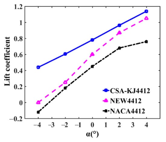
Figure 5.
Comparison of lift coefficient.
4. Aerodynamic Characteristics of CSA-KJ4412 Airfoil
4.1. Variation of Lift-Drag Ratio with Incoming Wind Speed
To observe the aerodynamic characteristics of the CSA-KJ4412 airfoil in the range of small angle of attack , the CL divided by the drag coefficient (CD) is defined as the lift-drag ratio coefficient (CL/CD), and when is −4°, −2°, 0°, 2° and 4°, respectively. The corresponding variation curves with incoming wind speed are drawn in Figure 6a–e.
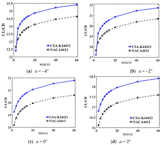
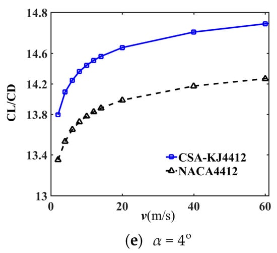
Figure 6.
Variation of lift-drag ratio coefficient with incoming wind speed under different angles of attack.
From Figure 6, it is evident that the lift-drag ratio shows a nonlinear trend with increasing incoming wind speed at different angles of attack. When the incoming wind speed is between 0 and 20 m/s, the lift-drag ratio of the airfoil increases rapidly, but the upward trend tends to level off after exceeding 20 m/s. The CL/CD of CSA-KJ4412 is slightly lower than that of NACA4412 when the angle of attack is negative and the incoming wind speed is 2 m/s, but it is higher at other incoming wind speeds. Regardless of the incoming wind speed, the lift-drag ratio of CSA-KJ4412 is significantly improved at non-negative attack angles. When comparing NACA4412 with CSA-KJ4412, the average lift-drag ratio of CSA-KJ4412 increases by 4.86%, 4.20%, 5.62%, 4.38%, and 3.61%, respectively, when the airfoil angle of attack is organized from a small to large algebraic value. This demonstrates that the aerodynamic performance of the airfoil optimized by the CSA-KJ method at the 0° attack angle shows the most improvement.
To more easily observe the change in the airfoil lift-drag ratio with a more intuitive angle of attack, the comparison curves under different incoming wind speeds are displayed in Figure 7a–c. It is clear that the CL/CD of CSA-KJ4412 at different angles of attack is higher than that of NACA4412 when the incoming wind speed is constant. In the range of the angle of attack of to , the CL/CD of the two airfoils initially increases before decreasing with ascending angles of attack. It then reaches a maximum when the angle of attack is or , and the lift-drag ratio of CSA-KJ4412 at a different angle of attack s is higher than that of NACA4412.
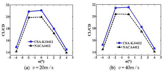
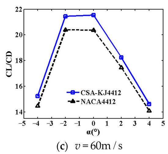
Figure 7.
Variation of lift-drag ratio with angle of attack at different incoming wind speeds.
4.2. Variation Curve of Pressure Difference
To further reveal the aerodynamic characteristics, the incoming wind speed is set to 12 m/s, and the pressure difference curves between the pressure surface and suction surface of CSA-KJ4412 and NACA4412 at different s are plotted in Figure 8a–f. It is not difficult to see that the maximum pressure difference of CSA-KJ4412 occurs at the chord length of 0.2 when the angle of attack does not exceed 15°. Additionally, the pressure difference at this time is significantly greater than that of NACA4412, while the pressure difference between the two airfoils is closer in the range of 0.5 to 0.7, and the maximum value of NACA4412 occurs near the leading edge. When the angle of attack is greater than 15°, the maximum pressure differences of NACA4412 and CSA-KJ4412 can be found near the leading edge and trailing edge of the airfoils. When the chord length is less than 0.3, the pressure difference of CSA-KJ4412 is smaller than that of NACA4412 and exhibits an upward trend. In the range of 0.4 to 1, the pressure difference of CSA-KJ4412 is significantly higher than that of NACA4412. In addition, when the angle of attack is not less than 15°, there is a peak value of pressure difference near the leading edge of CSA-KJ4412, which gradually decreases to nearly 0 Pa with increasing angle of attack.
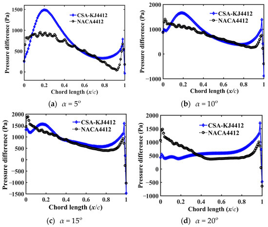
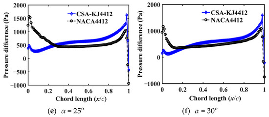
Figure 8.
Pressure difference of two airfoils at different angles of attack.
5. Conclusions
The CSA-KJ4412 airfoil was obtained by applying the proposed CSA-KJ method to optimize the NACA4412 method, and the aerodynamic characteristics were compared and analyzed. The main conclusions drawn are as follows:
- (1)
- The CSA-KJ method better improves the aerodynamic characteristics of the airfoil, whose profile described by the fourth-order constant-free polynomial function is relatively smooth. The average lift-drag ratio of CSA-KJ4412 increases by 4.53% compared with that of NACA4412.
- (2)
- At different angles of attack, the lift-drag ratio of CSA-KJ4412 at each incoming wind speed is higher than that of the original NACA4412. The difference in lift-drag ratio between the two airfoils uninterruptedly increases with the increase of incoming wind speed.
- (3)
- When the angle of attack is not more than 15°, the pressure difference distribution of CSA-KJ4412 is better than that of NACA4412, and the average pressure difference at each calculated attack angle is higher.
- (4)
- The CSA-KJ4412 airfoil has a better effect in the range of small angle of attack. The CSA-KJ method can be popularized and applied to the optimization of airfoils such as wings, aircraft engine turbines and wind turbine blades.
Author Contributions
Conceptualization, J.Z.; Funding acquisition, J.Z. and P.Z.; Methodology, J.Z.; Resources, P.Z.; Software, W.G. and H.J.; Validation, H.J.; Visualization, J.Z. and W.G.; Writing—review & editing, W.G. All authors have read and agreed to the published version of the manuscript.
Funding
This work was sponsored by the Program of Foundation of Science and Technology Commission of Shanghai Municipality (22dz1204202, 22dz1206005), National Natural Science Foundation of China (12172228, 11572187), and Natural Science Foundation of Shanghai (22ZR1444400).
Institutional Review Board Statement
Not applicable.
Informed Consent Statement
Not applicable.
Data Availability Statement
The data that support the findings of this study are available from the author, [J.P. Zhang], upon reasonable request.
Conflicts of Interest
The authors declare no conflict of interest.
References
- Sharma, P.; Gupta, B.; Pandey, M.; Sharma, A.K.; Mishra, R.N. Recent advancements in optimization methods for wind turbine airfoil design: A review. Mater. Today Proc. 2021, 47, 6556–6563. [Google Scholar] [CrossRef]
- Gui, X.; Xue, H.; Su, S.; Hu, Z.; Xu, Y. Study on aerodynamic performance of mine air duct horizontal axis wind turbine based on breeze power generation. Energy Sci. Eng. 2022, 10, 1132–1152. [Google Scholar] [CrossRef]
- Chitransh, A.; Kaur, S. Analysis of Airfoil for Horizontal axis Wind Turbine Blade. In Proceedings of the 2022 3rd International Conference for Emerging Technology (INCET), Belgaum, India, 27–29 May 2022; pp. 1–6. [Google Scholar] [CrossRef]
- Liu, T. Evolutionary understanding of airfoil lift. Adv. Aerodyn. 2021, 3, 37. [Google Scholar] [CrossRef]
- Spall, R.; Hodson, J. Educational Results Obtained Using an Improved Two-Dimensional Panel Method Code in Undergraduate Fluid Dynamics and Aerodynamics Courses. In Proceedings of the ASME Fluids Engineering Division Summer Meeting, Waikoloa, Hawaii, USA, 30 July–3 August 2017. [Google Scholar] [CrossRef]
- Gutierrez, E.; Quinn, D.B.; Chin, D.D.; Lentink, D. Lift calculations based on accepted wake models for animal flight are inconsistent and sensitive to vortex dynamics. Bioinspiration Biomim. 2016, 12, 016004. [Google Scholar] [CrossRef]
- Wang, S.; He, G.; Liu, T. Estimating lift from wake velocity data in flapping flight. J. Fluid Mech. 2019, 868, 501–537. [Google Scholar] [CrossRef]
- van Veen, W.G.; van Leeuwen, J.L.; Muijres, F.T. A chordwise offset of the wing-pitch axis enhances rotational aerodynamic forces on insect wings: A numerical study. J. R. Soc. Interface 2019, 16, 20190118. [Google Scholar] [CrossRef]
- Zhuang, K.Y.; Gao, C.D.; Li, Z.; Yan, D.L.; Fu, X.Q. Dynamic analyses of the Hydro-Turbine generator shafting system considering the hydraulic instability. Energies 2018, 11, 2862. [Google Scholar] [CrossRef]
- De Tavernier, D.; Ferreira, C.; Bussel, G. Airfoil optimisation for vertical-axis wind turbines with variable pitch. Wind. Energy 2019, 22, 547–562. [Google Scholar] [CrossRef]
- Akram, T.; Kim, M.-H. CFD Analysis and Shape Optimization of Airfoils Using Class Shape Transformation and Genetic Algorithm—Part I. Appl. Sci. 2021, 11, 3791. [Google Scholar] [CrossRef]
- Farhadi, A.; Rad, E.G.; Emdad, H. Aerodynamic Multi-Parameter Optimization of NACA0012 Airfoil Using Suction/Blowing Jet Technique. Arab. J. Sci. Eng. 2016, 42, 1727–1735. [Google Scholar] [CrossRef]
- Echavarria, C.; Hoyos, J.D.; Jimenez, J.H.; Suarez, G.; Saldarriaga, A. Optimal airfoil design through particle swarm optimization fed by CFD and XFOIL. J. Braz. Soc. Mech. Sci. Eng. 2022, 44, 561. [Google Scholar] [CrossRef]
- Kotinis, M.; Kulkarni, A. Multi-objective shape optimization of transonic airfoil sections using swarm intelligence and surrogate models. Struct. Multidiscip. Optim. 2011, 45, 747–758. [Google Scholar] [CrossRef]
- Cheng, C.; Xu, P.-F.; Cheng, H.; Ding, Y.; Zheng, J.; Ge, T.; Sun, D.; Xu, J. Ensemble learning approach based on stacking for unmanned surface vehicle’s dynamics. Ocean Eng. 2020, 207, 107388. [Google Scholar] [CrossRef]
- Tran-Ngoc, H.; Khatir, S.; Ho-Khac, H.; De Roeck, G.; Bui-Tien, T.; Wahab, M.A. Efficient Artificial neural networks based on a hybrid metaheuristic optimization algorithm for damage detection in laminated composite structures. Compos. Struct. 2020, 262, 113339. [Google Scholar] [CrossRef]
- Sumathi, R.; Venkatesulu, M. Segmenting MRI Brain Tumor Images Using Modified Cuckoo Search Optimization with Morphological Reconstruction Filters. In Proceedings of the IEEE International Conference on Intelligent Techniques in Control, Optimization and Signal Processing (INCOS), Tamilnadu, India, 11–13 April 2019; pp. 1–4. [Google Scholar] [CrossRef]
- Li, D.; Xu, S.; Qi, X.; Wang, N.; Cao, X. Variable step size adaptive cuckoo search optimization algorithm for phase diversity. Appl. Opt. 2018, 57, 8212–8219. [Google Scholar] [CrossRef]
- Liu, J.; Wang, D.; Luo, S. An Effective Constraint-Handling Improved Cuckoo Search Algorithm and Its Application in Aerodynamic Shape Optimization. IEEE Access 2020, 8, 139121–139142. [Google Scholar] [CrossRef]
- Cheng, J.; Wang, L.; Xiong, Y. An improved cuckoo search algorithm and its application in vibration fault diagnosis for a hydroelectric generating unit. Eng. Optim. 2017, 50, 1593–1608. [Google Scholar] [CrossRef]
- Rizzo, F.; D’Alessandro, V.; Montelpare, S.; Giammichele, L. Computational study of a bluff body aerodynamics: Impact of the laminar-to-turbulent transition modelling. Int. J. Mech. Sci. 2020, 178, 105620. [Google Scholar] [CrossRef]
- Kabir, A.; Akib, Y.M.; Hafiz, A.; Islam, M. Comparison between two Kline–Fogleman Modified (KFm) based Stepped Airfoils for better Aerodynamic Performance. In Proceedings of the 2019 2nd International Conference on Innovation in Engineering and Technology (ICIET), Dhaka, Bangladesh, 23–24 December 2019; pp. 1–5. [Google Scholar] [CrossRef]
- Kulkarni, D.S.; Rajani, B.N. Numerical Analysis of High Reynolds Number Effects on the Performance of GAW-1 Airfoil. In Design and Development of Aerospace Vehicles and Propulsion Systems; Springer: Singapore, 2021; pp. 425–432. [Google Scholar] [CrossRef]
- Yang, L.; Zhang, G. Analysis of Influence of Different Parameters on Numerical Simulation of NACA0012 Incompressible External Flow Field under High Reynolds Numbers. Appl. Sci. 2022, 12, 416. [Google Scholar] [CrossRef]
- Pellerin, N.; Leclaire, S.; Reggio, M. An implementation of the Spalart–Allmaras turbulence model in a multi-domain lattice Boltzmann method for solving turbulent airfoil flows. Comput. Math. Appl. 2015, 70, 3001–3018. [Google Scholar] [CrossRef]
- Rogowski, K.; Hansen, M.O.L.; Bangga, G. Performance Analysis of a H-Darrieus Wind Turbine for a Series of 4-Digit NACA Airfoils. Energies 2020, 13, 3196. [Google Scholar] [CrossRef]
- Sanei, M.; Razaghi, R. Numerical investigation of three turbulence simulation models for S809 wind turbine airfoil. Proc. Inst. Mech. Eng. Part A J. Power Energy 2018, 232, 1037–1048. [Google Scholar] [CrossRef]
- Wang, Q.; Zhao, Q. Unsteady aerodynamic characteristics investigation of rotor airfoil under variational freestream velocity. Aerosp. Sci. Technol. 2016, 58, 82–91. [Google Scholar] [CrossRef]
- Li, J.; Xu, Y.; Wu, Z. Kutta-Joukowski force expression for viscous flow. Sci. China Physics, Mech. Astron. 2014, 58, 90–94. [Google Scholar] [CrossRef]
- Yang, X.-S. Cuckoo Search and Firefly Algorithm: Overview and Analysis. Eng. Optim. 2013, 516, 1–26. [Google Scholar] [CrossRef]
- Jacobs, E.N.; Sherman, A. Airfoil section characteristics as affected by variations of the Reynolds number. NACA Tech. Rep. 1937, 586, 227–267. [Google Scholar] [CrossRef]
- Cai, D.; Xie, J.S.; Zhang, G.L. Research of optimization design about airfoil with multi-objective simulation. Mech. Res. Appl. 2013, 26, 49–51. [Google Scholar] [CrossRef]


Disclaimer/Publisher’s Note: The statements, opinions and data contained in all publications are solely those of the individual author(s) and contributor(s) and not of MDPI and/or the editor(s). MDPI and/or the editor(s) disclaim responsibility for any injury to people or property resulting from any ideas, methods, instructions or products referred to in the content. |
© 2023 by the authors. Licensee MDPI, Basel, Switzerland. This article is an open access article distributed under the terms and conditions of the Creative Commons Attribution (CC BY) license (https://creativecommons.org/licenses/by/4.0/).