Abstract
Recent studies on autonomous vehicles focus on improving driving efficiency and ignore driving comfort. Because acceleration and jerk affect driving comfort, we propose a comfort regenerative braking system (CRBS) that uses artificial neural networks as a vehicle-control strategy for braking conditions. An autonomous vehicle driving comfort is mainly determined by the control algorithm of the vehicle. If the passenger’s comfort is initially predicted based on acceleration and deceleration limits, the control strategy algorithm can be adjusted, which would be helpful to improve ride comfort in autonomous vehicles. We implement numerical analysis of the control strategy, ensuring reduced jerk conditions. In addition, backward propagation was applied to estimate the braking force limits of the regenerative braking systems more accurately. The developed algorithm was verified through the Car Sim and MATLAB/Simulink simulations by comparing them with the conventional braking system. The proposed CRBS offers effective regenerative braking within limits and ensures increased driving comfort to passengers.
1. Introduction
Autonomous electric vehicles are widely discussed in the vehicle industry owing to their integrated intelligence systems and effective energy-saving technology. When an electric vehicle applies regenerative braking, the motor acts as a generator that stores kinetic energy in the energy storage device or battery [1]. In the driving state, the motor uses energy from this battery. When applying the brake or during vehicle deceleration, the motor rotates backward and regenerates energy. This is known as a regenerative braking system. The energy flow in regenerative braking systems is depicted in Figure 1. High energy savings are achieved in electric or hybrid vehicles by effectively extracting the energy through the motor when applying the brake [2].
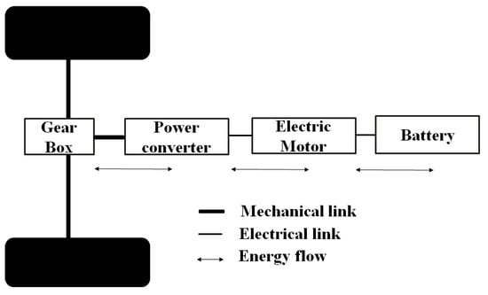
Figure 1.
Schematic representation of energy flow in regenerative braking systems.
The difference between normal braking and regenerative braking is shown in Figure 2, where the left image represents regenerative braking and the right image shows a discharging process, as seen in [3]. The speed management process and braking conditions are key parameters in vehicle energy efficiency. In traditional vehicles, the driver manually controls the vehicle’s speed. It is indeed challenging to maximize the efficiency of a regenerative braking system because road conditions can vary significantly and cannot be easily predicted. Traditional methods for maximizing efficiency typically rely on accurate traffic information to determine the most efficient way to use regenerative braking. However, this can be difficult to obtain in real-time, especially if the vehicle is traveling on unfamiliar roads or in areas with limited traffic data. One way to overcome this challenge is to use sensors and various technologies to continuously monitor the road conditions and adjust the braking strategy. This can help to optimize the efficiency of the regenerative braking system and improve the overall performance of the vehicle.
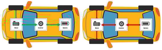
Figure 2.
Comparison of regenerative braking and discharging process.
The machine learning method can appropriately mimic human driving because it can train the characteristics of human driving [4]. Many researchers have conducted studies to predict a vehicle’s acceleration and velocity by using artificial neural network methods. Hou et al. [5] applied genetic algorithms to evaluate the driving distance and state of charge (SOC) by using dynamic programming to generate an SOC curve. Liu et al. [6] developed a prediction algorithm by combining neural network and Markov chain methods according to energy conditions in plug-in hybrid electric vehicles. Zhang et al. [7] applied the support vector method (SVM) and exponential prediction model to predict vehicle speed.
The above researchers evaluated several parameters, such as road speed and traffic information, but failed to design a comfortable system. Xu and Mohamed Elbanhawi [8] measured riding comfort based on the vibrations transmitted to a passenger according to the road and vehicle conditions. In the vehicle driving state, the acceleration acting on the passenger was analyzed by varying the values of the influencing factors. Naseri et al. [9] presented a method to improve riding comfort during braking, in which the electromechanical brake was applied in a longitudinal acceleration direction to reduce jerk (the derivative of acceleration). In addition, they designed a controller to lower discomfort and improve riding comfort.
Yuchuan et al. [10] researched the improvement of a passenger’s comfort in autonomous vehicles, proposed measuring the degree of discomfort according to the speed and road surface conditions, and evaluated different speed control strategies. The ride comfort felt by passengers is key to systemic vehicle development because it is an important indicator that considerably influences vehicle performance. Many studies on vehicle braking and avoiding extreme situations during driving require the maximum performance of the vehicle [11]. The ride comfort and vehicle jerk have a complex relationship and exhibit nonlinear characteristics when compared to a biomechanically measured human response [12]. The international standard ISO 2631–1997 has three orientations and positions, as shown in Table 1. Considering these reference standards, using the weighted root-mean-square acceleration is recommended when considering ride comfort [13,14].

Table 1.
Comparison of root-mean-square acceleration (RMSA) and human sensation according to ISO 2631-1997 [14].
This paper proposes a comfort regenerative braking system (CRBS) to control the regenerative braking force. The novelty of this research is that the regenerative power is generated within the comfort range specified by ISO 2631-199, but the traditional braking method lacks a definite control strategy during braking. In addition, the proposed model predicts braking and speed limits by using backpropagation to ensure driving comfort. The acceleration and deceleration are reduced at the start, slow, and stop of vehicle motion by using numerical analysis with a tangent function as a speed change graph. CarSim and MATLAB/Simulink were used to validate the developed backpropagated algorithm. The generated data were input into the neural network algorithm.
2. Methodology
Traditional braking without a control strategy can exceed permissible safety limits, leading to uncomfortable driving. However, a strategy to control the acceleration and deceleration limits during starting, slowing, or stopping of the vehicle would ensure driving comfort within the autonomous vehicle by maintaining a comfortable range. This study proposes an artificial neural network-based control strategy ensuring both high regenerative power and driving comfort, as shown in Figure 3 and Figure 4. In a conventional regenerative braking system during vehicle stop conditions there will be high ride comfort with reduced regenerated power. Similarly, during sudden, unavoidable circumstances, when regenerative brake is applied, even high energy generated causes high ride discomfort. With the proposed CRBS method, even in the sudden harsh conditions, efficient energy is generated with high ride comfort.
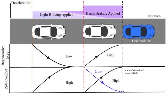
Figure 3.
Ride comfort and efficiency improved with CRBS proposed method.
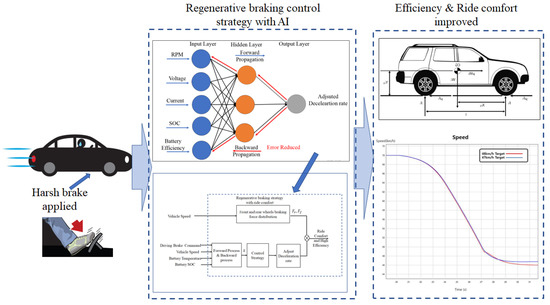
Figure 4.
Regenerative braking control strategy with CRBS method.
The control strategy of regenerative braking was explained as follows, when the braking command received from the sensors, the appropriate deceleration rate was predicted and set through the backpropagation method that meets the requirement of the condition of the vehicle to achieve the ride comfort as depicted in the Figure 4. The main purpose of the control strategy to produce efficient regenerative braking without ride discomfort.
A separate acceleration sensor is attached to the vehicle to monitor road conditions and deceleration.
The control strategy in self-driving vehicles depends on the vehicle’s surroundings, which are recorded by appropriate sensors and cameras. Time to collision (TTC) recognizes the distance to an obstacle or preceding vehicle, as shown in Figure 5, and calculates the expected collision time. The autonomous vehicle controls the steering and braking of the vehicle in response to TTC. Target speed and time to reach the target speed are controlled by the hyperbolic tangent function and control the braking in self-driving vehicles. The following equation was proposed to obtain the required vehicle speed,
where
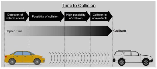
Figure 5.
Schematic diagram of time to collision.
- v: vehicle speed,
- v0: initial value of vehicle speed,
- b: difference between initial and target vehicle speed,
- : time to reach target speed,
- t: time to collision,
- k: model constant, and
- tanh: hyperbolic tangent function.
2.1. Numerical Analysis of Required Regenerative Braking Force
In this section, we analyzed the acceleration, velocity, and jerk to set the range of the regenerative force. Thus, the vehicle can reach the target speed with a predefined rather than random velocity. For example, if the brake is suddenly applied, the sudden stop can create great discomfort for the passengers. A numerical analysis was performed to solve this issue and is explained as follows. Suppose that when the brake is applied, the vehicle speed decelerates from 30 to 10 km/h in 20 s. If k is decreased, the time to reach the target speed increases, according to Equation (1). It is calculated that driving comfort is possible when k is 0.25. Similarly, we calculated acceleration and jerk parameters, from which the regenerative force could be derived. The data obtained from the autonomous vehicle were input of a multilayer perceptron algorithm.
2.1.1. Evaluation of Required Braking Force
To ensure ride comfort, the motor torque must be evaluated along with acceleration and jerk [15]. According to the magnitude of k, the slope of the velocity change curve as shown in Figure 6 was obtained. The maximum deceleration was also determined.
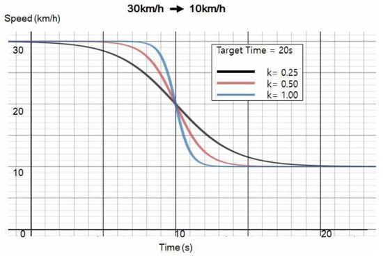
Figure 6.
Speed graph for varying values of k as vehicle slows from 30 to 10 km/h. Target time was set to 20 s. When constant k is decreased, the vehicle slowing time increases.
As k decreases, the vehicle takes longer to slow, increasing riding inconvenience. If k is greatly reduced, the vehicle takes a very long time to slow. Hence, k affects the vehicle speed, as shown in Equation (1) [16,17].
Equation (1) evaluates the asymptotic nature of the hyperbolic tangent function. However, it is complex to implement a small constant to control the degree of deceleration such that we have the following equation [18],
where
- b*: difference between initial and target vehicle speed, and
- v*: initial vehicle speed.
The vehicle speed is altered by varying the tanh function in Equation (5). After introducing the constant and evaluating k, the corresponding speed change can be modeled by using the following equation,
where
- 0: set point to begin deceleration, and
- artanh: inverse hyperbolic tangent function.
k is obtained from Equation (5), and the time to reach the target speed is identified from the vehicle’s speed [19,20]. The speed is controlled by varying the tanh function, as shown in the speed graph in Figure 7.
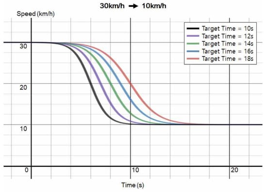
Figure 7.
Proposed deceleration model. Speed graph showing time taken to reach target speed. Plotted by using k from Equation (5). The tanh function controls vehicle speed.
- a: Acceleration,
- sech: Hyperbolic secant function.
Jerk is the change in acceleration [21] and can be derived by differentiating Equation (6) to obtain Equation (7) as follows,
By solving Equations (6) and (7) by using the graph in Figure 7, the graphs in Figure 8 were plotted.
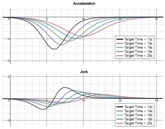
Figure 8.
Proposed deceleration model: acceleration and jerk.
The deceleration and the corresponding jerk are important parameters to achieve riding comfort and the values obtained are 2.5 m/s2 and 2.94 m/s3. Lowering the values can help achieve a more comfortable ride. Maximum acceleration is achieved when time is half of , which means () and is expressed in Equation (8). Maximum jerk is obtained by differentiating Equation (9) at zero, as expressed in Equation (10):
2.1.2. Evaluation of Required Force
The vehicle’s weight is proportional to the force acting on it. Hence, Equation (6) was used to derive the force required by a vehicle during deceleration as follows [22,23]:
where
- Fb: Total braking force,
- Wa: Gross vehicle weight.
When a vehicle stops accelerating and enters into a deceleration state, it moves forward by inertial force. However, the road conditions and driving vibrations can change the vehicle’s speed. Therefore, the resistance force required to control the vehicle is expressed as follows,
where
- : actual force required, and
- : driving resistance.
The required braking force may have a negative value, indicating that the vehicle starts decelerating. The change in driving resistance according to the weight and speed of the vehicle is demonstrated in the Results section.
2.2. Modeling of Artificial Intelligence Algorithm
An artificial neural network is used in the present study to set the acceleration and deceleration limits to ensure ride comfort. It consists of three layers: the input, hidden, and output layers. Each layer contains artificial neurons. A schematic representation is shown in Figure 9.
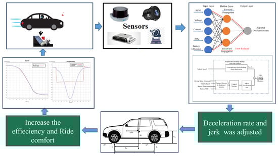
Figure 9.
Schematic representation of neural networks controlling the vehicle.
The environmental data, collected by using the TTC and sensors, are fed into the neural network. After training the model with comfortable riding conditions, vehicle control is possible. The basic input values such as vehicle speed (revolutions per minute), voltage, current drawn from battery, battery SOC, and battery efficiency are input into the input layer [24,25]. The activation function at each hidden layer reduces the error in the output layer. The final output is the basic principle in the forward and backward propagation model. Figure 10 shows the algorithm for the proposed CRBS method.
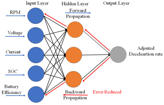
Figure 10.
Layout of artificial neural network model of forward and backward propagation.
The backpropagation method updates the weights in each layer and finds the optimal learning result while propagating errors in the reverse direction. In algorithms used for forward neural network training, the output is obtained from forward propagation, by learning the hidden layer by backpropagating the error between the current and target values.
During forward propagation through the initial set weights, the error between the output and target values is transmitted to each layer. The weight is modified toward the minimized error, and this is repeated until an acceptable error is reached. The higher the vehicle’s weight and faster the vehicle’s speed, the more braking force is required. In addition, the weight of the vehicle changes frequently depending on the number of passengers and load.
Figure 11 represents regenerative braking strategy. Front and rear wheel forces were distributed equally on the vehicle. By receiving the driving brake force command, backward propagation predicts the required force condition and adjusts the deceleration rate to achieve comfortable ride conditions. This proposed CRBS method was set to operate for 10 seconds, and during this set time, the deceleration rate was adjusted. The speed change in the vehicle depends on various factors, including the weight, speed, road surface condition, and road angle [26]. The regenerative braking force cannot exceed the maximum output of the motor when applying the control strategy. According to Equation (8), the speed must be controlled to ensure the regenerative braking force is within the limit. In addition, the deceleration and time required to reach the target must be obtained; deceleration can be obtained by controlling the throttle and regenerative braking. A flowchart of the proposed CRBS method is shown in Figure 12. The results predicted by using this algorithm were validated through simulations that use CarSim and MATLAB/Simulink and which are explained in the Results section [27].
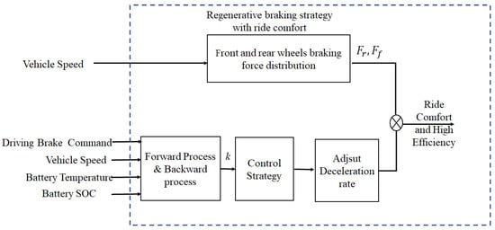
Figure 11.
Regenerative braking control strategy with backpropagation method).
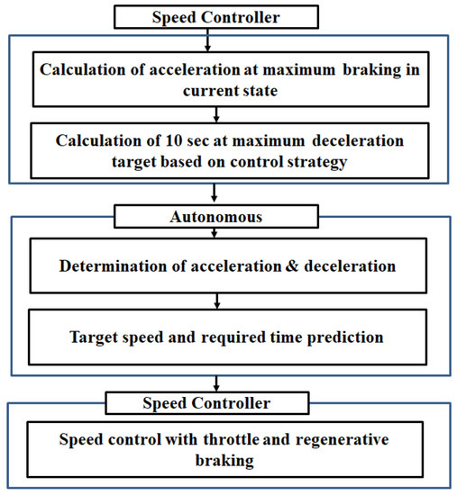
Figure 12.
Flowchart of proposed comfort regenerative braking system method.
2.3. Dynamic Modelling
In a hybrid vehicle, the motor converts battery energy into kinetic energy to drive the vehicle. The motor torque is expressed in terms of the efficiency and angular velocity [28,29], as follows,
where
- Tm: motor torque,
- : motor efficiency, and
- : motor angular speed.
Figure 13 shows the MATLAB/Simulink results for the efficiency map of the motor and represents the motor efficiency according to speed and torque during the regenerative braking process.
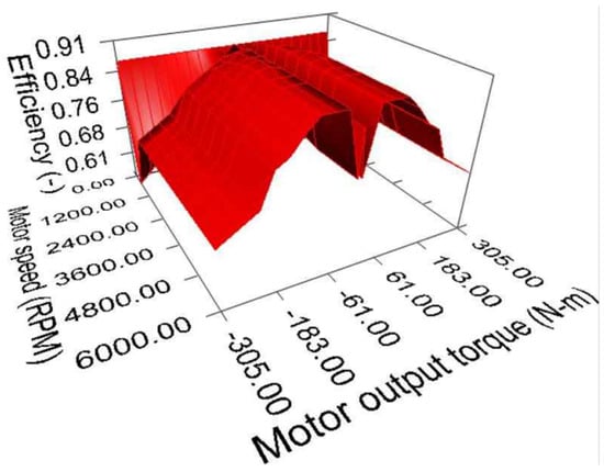
Figure 13.
Motor efficiency map comparing motor output torque, motor speed, and efficiency: RPM, revolutions per minute.
The relationship between voltage V and current I is expressed as follows,
where
- P: motor power,
- I: current, and
- V: voltage.
Finally, based on the relationship between the motor’s electrical output and efficiency, the electrical energy is converted into kinetic energy for regenerative braking. However, some energy loss can occur when converting kinetic energy into electrical energy. The torque performance curve of the motor, simulated by MATLAB/Simulink, is represented in Figure 14.
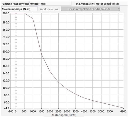
Figure 14.
Motor torque curve.
The running resistance of the vehicle is the sum of different resistances as follows,
where
- : rolling resistance,
- : wind drag,
- : climbing resistance, and
- : acceleration resistance.
Rolling resistance is the resistance that a vehicle receives when driving on a horizontal road surface; it is mainly experienced by the tire,
where
- : rolling resistance coefficient, and
- W: total vehicle weight.
Air resistance is the resistance between the air and a moving object. It is proportional to the projected area of the vehicle and square of the driving speed. We have
where
- : air resistance coefficient,
- A: projected vehicle area, and
- : resistance speed.
Climbing resistance is the resistance acting in the opposite direction of the vehicle traveling on an inclined plane. We have
where
- : angle of inclination.
Acceleration resistance is the force required to change the vehicle’s speed and is expressed as follows,
where
- a: acceleration,
- g: gravitational acceleration, and
- : coefficient of inertia of rotating parts.
The total weight of the vehicle is distributed equally between the front and rear wheels, as shown in Figure 15, that depicts the forces acting when applying the brakes. By using Figure 15, we evaluate the changes in the force acting on the front and rear wheels of the vehicle as follows,
where
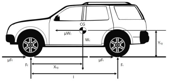
Figure 15.
Distribution of vehicle weight.
- : front wheel vertical force,
- : rear wheel vertical force,
- : horizontal distance between center of gravity and front axle,
- I: wheelbase length
- : distance from ground to center of gravity,
- : vehicle weight
- : center of gravity, and
- : coefficient of friction.
3. Experiment
3.1. Vehicle Dynamics Simulation
CarSim simulation software was used to consider the vehicle dynamics when applying the brake on a vehicle. The simulation was performed by receiving speed control commands from MATLAB/Simulink, and the output data were obtained by using dynamic modeling in CarSim. A detailed layout is depicted in Figure 16.
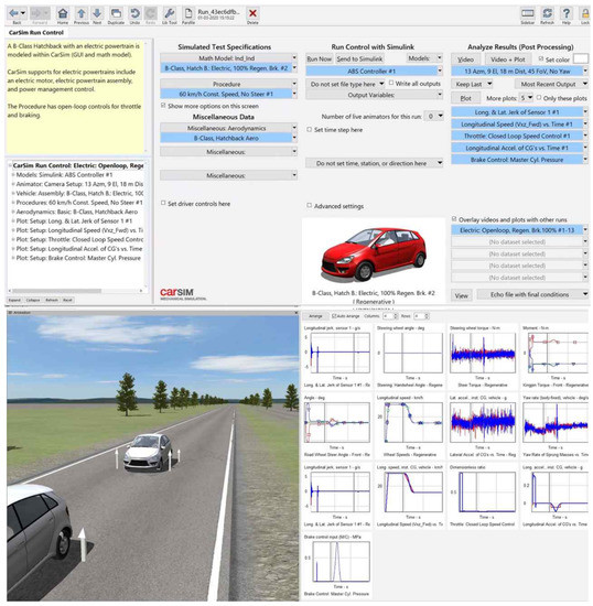
Figure 16.
CarSim configuration.
3.2. MATLAB/Simulink Environment Configuration
Figure 17 shows the MATLAB/Simulink layout for evaluating speed, torque, and motor efficiency, with arbitrary values input in the simulation. Target autonomous driving speed and corresponding target arrival time were obtained from this simulation. The data extracted through CarSim were the vehicle’s speed, battery level, pressure, current, and battery efficiency, based on the predicted of braking limit.
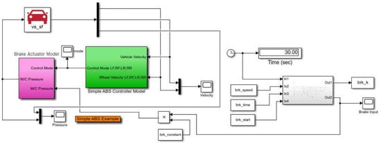
Figure 17.
MATLAB/Simulink simulation model: target speed, required acceleration, and deceleration as per the applied regenerative force were obtained from this simulation.
The speed control unit operated for 10 s based on the supplied braking limit constant. We set the maximum deceleration by using the CRBS, created a target speed graph with a proportional integral controller, and simulated the model by inputting throttle and regenerative braking values to the CarSim environment.
3.3. AI Training of Proposed System
The required braking force must be predicted from the required velocity and deceleration based on the current vehicle state. Such a prediction system can be modeled and evaluated by using artificial intelligence algorithms. The vehicle’s weight in the CarSim program ranged from 1134 to 1434 kg, as shown in Figure 18.
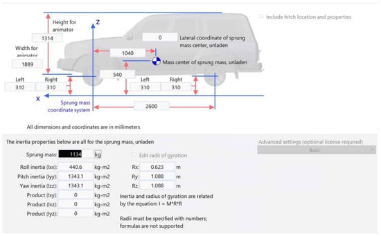
Figure 18.
Simulation with varying vehicle weights: by applying different vehicle weights, the inertia and radius of gyration were obtained.
In this study, the speed, voltage, current, battery efficiency, and battery level data were input to the neural network, and the corresponding deceleration was generated. The learning data for the multilayer perceptron was obtained by varying the weight and initial speed of the vehicle and the road surface type. Maximum deceleration was simulated to measure the comfort range of passengers from the corresponding jerk values.
4. Results
In this section, the conventional braking and proposed (CRBS) are compared.
4.1. Improved Riding Comfort
4.1.1. Case 1: Changing Speed from 30 to 15 km/h
Figure 19, Figure 20 and Figure 21 shows comparison of the speed, acceleration, and jerk of the conventional braking control and proposed CRBS methods when changing the speed of the vehicle from 30 to 15 km/h. The results were summarised below in Table 2.
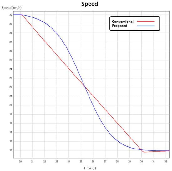
Figure 19.
Speed comparison of conventional braking and proposed method when changing speed from 30 to 15 km/h. Both control methods reached 15 km/h within 10 s.
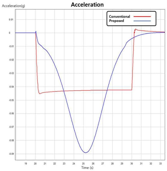
Figure 20.
Acceleration comparison when changing speed from 30 to 15 km/h. The maximum deceleration obtained by CRBS was −0.09 g, and that of the conventional method was −0.04 g.
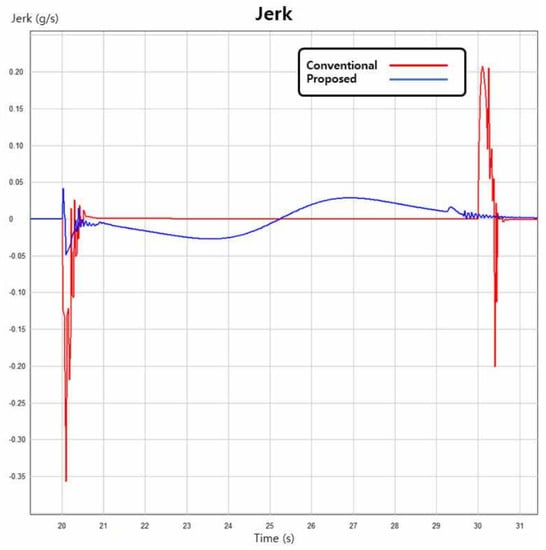
Figure 21.
Jerk comparison when changing speed from 30 to 15 km/h. The maximum jerk controlled by CRBS was −0.05 g/s, and that of the conventional method was 0.35 g/s.
Table 2.
Comparison of the conventional and CRBS method when vehicle decelerated from 30 km/h to 15 km/h.
4.1.2. Case 2: Changing Speed from 30 to 10 km/h
Figure 22, Figure 23 and Figure 24 represents the speed, acceleration, and jerk of the conventional braking control and proposed CRBS methods when changing the speed of the vehicle from 30 to 10 km/h. The results were summarised below in Table 3.
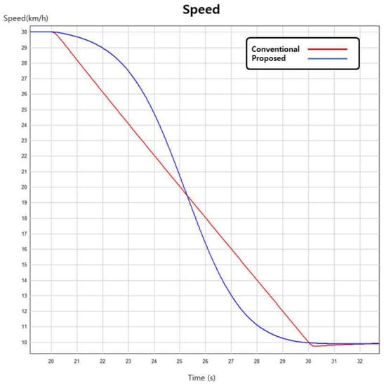
Figure 22.
Speed comparison of conventional braking and proposed method when changing speed from 30 to 10 km/h. Both control methods reached 10 km/h within 10 s.
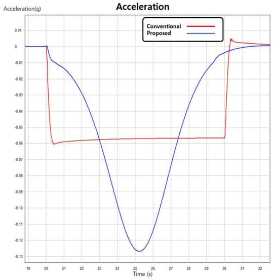
Figure 23.
Acceleration comparison when changing speed from 30 to 10 km/h. The maximum deceleration obtained by CRBS was −0.125 g, and that of the conventional method was −0.05 g.
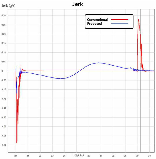
Figure 24.
Jerk comparison when changing speed from 30 to 10 km/h. The maximum jerk controlled by CRBS was −0.12 g/s, and that of the conventional method was 0.39 g/s.
Table 3.
Comparison of the conventional and CRBS method when vehicle decelerated from 30 km/h to 10 km/h.
4.2. Model Trained by Artificial Intelligence
The maximum deceleration target was obtained by training the model by using the artificial neural network method the following results were obtained.
4.2.1. Case 3: Vehicle Weight Comparison (Initial Speed 50 km/h)
Figure 25 shows the maximum target speed for different vehicle weights controlled by the trained artificial neural network model.
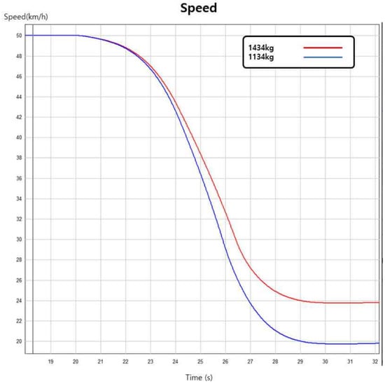
Figure 25.
Maximum target speed comparison according to vehicle weight. Corresponding to the vehicle weight changing from 1134 to 1434 kg, the maximum target speed was adjusted from 20 to 24 km/h.
4.2.2. Case 4: Maximum Braking Comparison (Initial Speed 50 km/h)
Figure 26 shows the maximum braking when setting the target speed as either 19 or 20 km/h.
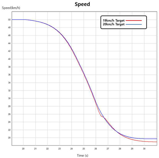
Figure 26.
Maximum braking comparison when setting target speed as 19 km/h and 20 km/h.
4.2.3. Case 5: Maximum Braking Comparison (Initial Speed 70 km/h)
Figure 27 shows the maximum braking comparison for target speeds of 46 and 47 km/h when the initial speed of the vehicle is 70 km/h.
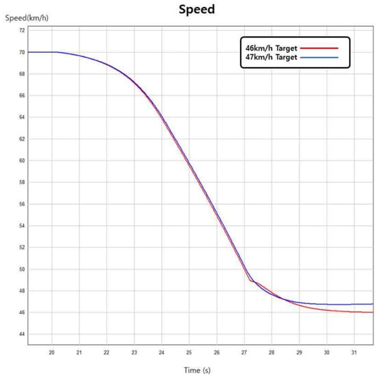
Figure 27.
Maximum braking comparison when setting target speed as 46 and 47 km/h. Note that the initial speed is 70 km/h.
5. Discussion
5.1. Improved Riding Comfort and Relationship with Speed Change
In the process of changing the vehicle speed, acceleration and jerk have a large influence on the riding comfort of passengers. Jerk represents the rate of change of the acceleration and known to have an impact on driving comfort that is consistent with subjective human perception. It has been reported that passengers feel more comfortable when the amplitudes of jerk and deceleration are smaller [11], and Hubbard [30] found that jerk should not exceed 2.94 m/s3 (0.3 g/s) to ensure passenger comfort. In addition, Powell’s deceleration domain, in which passengers feel comfortable, was reported as 1.3 m/s2 ∼ 2.5 m/s2 (0.134 g ∼ 0.257 g). Considering the maximum regions of passenger comfort, the results of the CRBS approach show that the proposed method is effective in improving riding comfort.
For Cases 1 and 2, Figure 19 and Figure 22 indicate that the vehicle speed decreased by balancing the deceleration and riding comfort when applying the CRBS method. Conversely, when the conventional brake control is applied, the vehicle stops suddenly without considering the riding comfort. Furthermore, by observing the corresponding acceleration shown in Figure 20 and Figure 23, the proposed method reduces the vehicle speed more gently than the conventional method, which suddenly reduces the vehicle’s acceleration. This can be more clearly observed in the low jerk of the proposed method compared to that of the conventional braking system (Figure 21 and Figure 24). It should be emphasized that the maximum acceleration (−0.089 and −0.126 g for Cases 1 and 2) and jerk (−0.05 g/s ∼ 0.03 g/s and −0.12 g/s ∼ 0.05 g/s for Cases 1 and 2) of the CRBS method remain within the Powell and Hubbard domains. In contrast, the jerk results (−0.35 g/s ∼ 0.21 g/s and −0.38 g/s ∼ 0.28 g/s for Cases 1 and 2) of the conventional braking system fail to meet the domains due to the sudden braking.
5.2. Relationship between Vehicle Weight and Maximum Target Speed
In general, as the heavy weighted vehicle requires more deceleration force, a large amount of jerk during deceleration is required to reach the target speed in a given time. In this aspect, a naive target speed calculation of regenerative braking force may lead to riding discomfort. From the Result section, when the weight of the vehicle increased from 1134 to 1434 kg, the maximum braking target speed was adjusted from 20 km/h to 24 km/h to meet the jerk comfort domain (Figure 25). For example, the maximum braking speed estimated by CRBS when at 50 km/h, was calculated as 20 km/h for a 1134 kg vehicle (Figure 26). However, when the maximum braking speed was set as 20 km/h manually, the CRBS model modified the deceleration to meet the comfortable jerk domain (Figure 26). Similarly, the maximum braking speed estimated by CRBS at 70 km/h for a 1200 kg vehicle, was calculated as 48 km/h (Figure 27).
5.3. Applications and Limitations of the Proposed CRBS Method
Considering that regenerative braking is relatively weak compared to normal braking, the initial scope of this study was to evaluate the effective performance of the proposed CRBS method when the vehicle was moving in a straight line. The results of the CRBS method showed that the jerk profile of the vehicle was generated by considering the comfort domain as a prime constraint.
However, there are some limitations of the proposed CRBS method for regenerative braking, specifically when it is used in turning or reversing situations. In these situations, the vehicle may need to stop quickly to avoid a collision, which could require a rapid application of braking force. In such cases, the performance of the CRBS method may be limited, and it may be necessary to rely on conventional brakes to provide the necessary stopping power. In the future, it will be important to carefully consider the performance of the CRBS method in various driving conditions, such as turning, uphill, downhill, and reversing, to ensure that it provides adequate braking force and safety for the vehicle and its occupants.
In addition, the major challenges of implementing an AI-based regenerative braking system in practice, mainly concerned with the requirement of high precision equipment to control heavy vehicle when subjected to the extensively high force. In addition, cost and feasibility of implementing such a system on a large scale. Furthermore, robust and accurate sensors were required to collect data on the vehicle’s speed and acceleration to implement AI algorithms and make control decisions in real time. Finally, very careful integration with the existing control systems in a vehicle is required. Overall, this type of evaluation can help to further validate the system and demonstrate its potential value in practical applications.
5.4. Control Strategy of Regenerative Braking during Emergency Braking
During emergency braking, it is important to apply the maximum braking force in order to bring the vehicle to a stop as quickly and safely as possible. This requires the control strategy of the regenerative braking, as the power required to dissipate during emergency braking can be much greater than the power available for acceleration, especially in high-performance vehicles. For these reasons, it is necessary to control the force in order to produce the desired total braking output. This control strategy is designed to meet the required acceleration during sudden deceleration of the vehicle, as shown in Figure 26 and Figure 27, and the deceleration rate was adjusted to meet the required vehicle speed during the sudden deceleration of the vehicle, as shown in Figure 19 and Figure 22. From Table 2 and Table 3, with adjusted deceleration rate the jerk magnitude was also reduced with the proposed CRBS method. Unlike conventional braking systems, the proposed CRBS method ensures a reliable braking system with the calculated acceleration according to the speed profile as given in Equation (6). With this, the required jerk has been predicted as shown in Equation (7). The optimization of the braking force to meet the specific needs of the vehicle and its occupants in different driving conditions was analysed.
6. Conclusions
This study proposed the CRBS speed control method that requires riding comfort to be within the ISO 2631-1997 safety limits. The main objective of this method is to reduce the ride discomfort with high energy efficiency, during the application of regenerative braking in the vehicle. The effective regenerative force must be controlled based on the deceleration conditions to achieve a comfort range. To reduce ride discomfort, control strategy for regenerative braking with CRBS method was modelled to predict and correct the deceleration rates and generate an effective comfort ride at various target speeds. The prediction of deceleration rates was done with the backward propagation method. During regenerative braking, the braking force might exceed motor output. Hence, braking power should be limited to achieve driving comfort by predicting the vehicle and surrounding conditions. Backward propagation method was used for accurate predictions through an artificial neural network. CarSim and MATLAB/Simulink were used to validate the developed algorithm, and the vehicle acceleration and deceleration were compared for traditional braking and CRBS methods. When the normal braking method was applied, the driving comfort was beyond the allowed range, but the proposed CRBS method maintains the comfort limit not to be exceeded, and driving comfort was achieved. Hence, the CRBS method is recommended for application in autonomous electric vehicles. The proposed method can satisfy the comfort range of passengers in autonomous electric vehicles with minimum deceleration.
Author Contributions
Conceptualization, M.H.H.; methodology, G.S.L. and H.R.C.; software, G.S.L. and E.K.; validation, G.S.L. and H.R.C.; formal analysis, G.S.L. and E.K.; investigation, G.S.L. and H.W.K.; resources, H.R.C.; data curation, G.S.L. and T.T.; writing—original draft preparation, G.S.L. and T.T.; writing—review and editing, S.Y. and T.T.; visualization, H.R.C. and M.H.H.; supervision, H.R.C. and M.H.H.; project administration, H.R.C. and M.H.H.; funding acquisition, H.R.C. and M.H.H. All authors have read and agreed to the published version of the manuscript.
Funding
This study has been conducted with the support of the Korea Institute of Industrial Technology as Development of Core Technologies for a Working Partner Robot in the Manufacturing Field KITECH EO-22-0009.
Data Availability Statement
No new data were created or analyzed in this study. Data sharing is not applicable to this article.
Conflicts of Interest
The authors declare there is no conflict of interest.
References
- von Albrichsfeld, C.; Karner, J. Brake System for Hybrid and Electric Vehicles; Technical Report, SAE Technical Paper; SAE International: Warrendale, PA, USA, 2009. [Google Scholar]
- Wager, G.; Whale, J.; Braunl, T. Performance evaluation of regenerative braking systems. Proc. Inst. Mech. Eng. Part D J. Automob. Eng. 2018, 232, 1414–1427. [Google Scholar] [CrossRef]
- Lv, C.; Zhang, J.; Li, Y.; Yuan, Y. Mechanism analysis and evaluation methodology of regenerative braking contribution to energy efficiency improvement of electrified vehicles. Energy Convers. Manag. 2015, 92, 469–482. [Google Scholar] [CrossRef]
- Zhang, Y.; Xie, H.; Song, K. An Optimal Vehicle Speed Planning Algorithm for Regenerative Braking at Traffic Lights Intersections based on Reinforcement Learning. In Proceedings of the 2020 4th CAA International Conference on Vehicular Control and Intelligence (CVCI), Hangzhou, China, 18–20 December 2020; pp. 193–198. [Google Scholar]
- Lei, Z.; Qin, D.; Hou, L.; Peng, J.; Liu, Y.; Chen, Z. An adaptive equivalent consumption minimization strategy for plug-in hybrid electric vehicles based on traffic information. Energy 2020, 190, 116409. [Google Scholar] [CrossRef]
- Xie, S.; Hu, X.; Xin, Z.; Li, L. Time-efficient stochastic model predictive energy management for a plug-in hybrid electric bus with an adaptive reference state-of-charge advisory. IEEE Trans. Veh. Technol. 2018, 67, 5671–5682. [Google Scholar] [CrossRef]
- Zhang, Y.; Chen, Z.; Li, G.; Liu, Y.; Huang, Y. A Novel Model Predictive Control Based Co-Optimization Strategy for Velocity Planning and Energy Management of Intelligent PHEVs. IEEE Trans. Veh. Technol. 2022, 71, 12667–12681. [Google Scholar] [CrossRef]
- Elbanhawi, M.; Simic, M. Sampling-based robot motion planning: A review. IEEE Access 2014, 2, 56–77. [Google Scholar] [CrossRef]
- Naseri, F.; Farjah, E.; Ghanbari, T. An efficient regenerative braking system based on battery/supercapacitor for electric, hybrid, and plug-in hybrid electric vehicles with BLDC motor. IEEE Trans. Veh. Technol. 2016, 66, 3724–3738. [Google Scholar] [CrossRef]
- Du, Y.; Liu, C.; Li, Y. Velocity control strategies to improve automated vehicle driving comfort. IEEE Intell. Transp. Syst. Mag. 2018, 10, 8–18. [Google Scholar] [CrossRef]
- Hoberock, L.L. A Survey of Longitudinal Acceleration Comfort Studies in Ground Transportation Vehicles; Technical Report, Council for Advanced Transportation Studies; The University of Texas at Austin: Austin, TX, USA, 1976. [Google Scholar]
- Nawayseh, N.; Griffin, M. Non-linear dual-axis biodynamic response to vertical whole-body vibration. J. Sound Vib. 2003, 268, 503–523. [Google Scholar] [CrossRef]
- Ciloglu, H.; Alziadeh, M.; Mohany, A.; Kishawy, H. Assessment of the whole body vibration exposure and the dynamic seat comfort in passenger aircraft. Int. J. Ind. Ergon. 2015, 45, 116–123. [Google Scholar] [CrossRef]
- An, N. Mechanical Vibration and Shock—Evaluation of Human Exposure to Whole-Body Vibration—Part 1: General Requirements; Acoustical Society of America: Melville, NY, USA, 2007. [Google Scholar]
- Maia, R.; Mendes, J.; Araújo, R.; Silva, M.; Nunes, U. Regenerative braking system modeling by fuzzy Q-Learning. Eng. Appl. Artif. Intell. 2020, 93, 103712. [Google Scholar] [CrossRef]
- Heydari, S.; Fajri, P.; Rasheduzzaman, M.; Sabzehgar, R. Maximizing regenerative braking energy recovery of electric vehicles through dynamic low-speed cutoff point detection. IEEE Trans. Transp. Electrif. 2019, 5, 262–270. [Google Scholar] [CrossRef]
- Zuo, L.; Zhang, P.S. Energy harvesting, ride comfort, and road handling of regenerative vehicle suspensions. J. Vib. Acoust. 2013, 135, 011002. [Google Scholar] [CrossRef]
- Heydari, S.; Fajri, P.; Husain, I.; Shin, J.W. Regenerative braking performance of different electric vehicle configurations considering dynamic low speed cutoff point. In Proceedings of the 2018 IEEE Energy Conversion Congress and Exposition (ECCE), Portland, OR, USA, 23–27 September 2018; pp. 4805–4809. [Google Scholar]
- Pisu, P.; Rizzoni, G. A comparative study of supervisory control strategies for hybrid electric vehicles. IEEE Trans. Control Syst. Technol. 2007, 15, 506–518. [Google Scholar] [CrossRef]
- Zhang, B.; Zhang, J.; Shen, T. Optimal control design for comfortable-driving of hybrid electric vehicles in acceleration mode. Appl. Energy 2022, 305, 117885. [Google Scholar] [CrossRef]
- Tang, X.; Duan, Z.; Hu, X.; Pu, H.; Cao, D.; Lin, X. Improving ride comfort and fuel economy of connected hybrid electric vehicles based on traffic signals and real road information. IEEE Trans. Veh. Technol. 2021, 70, 3101–3112. [Google Scholar] [CrossRef]
- Fajri, P.; Lee, S.; Prabhala, V.A.K.; Ferdowsi, M. Modeling and integration of electric vehicle regenerative and friction braking for motor/dynamometer test bench emulation. IEEE Trans. Veh. Technol. 2015, 65, 4264–4273. [Google Scholar] [CrossRef]
- Zhang, J.; Yang, Y.; Hu, M.; Yang, Z.; Fu, C. Longitudinal–vertical comprehensive control for four-wheel drive pure electric vehicle considering energy recovery and ride comfort. Energy 2021, 236, 121417. [Google Scholar] [CrossRef]
- Min, K.; Yeon, K.; Jo, Y.; Sim, G.; Sunwoo, M.; Han, M. Vehicle deceleration prediction based on deep neural network at braking conditions. Int. J. Automot. Technol. 2020, 21, 91–102. [Google Scholar] [CrossRef]
- Lv, C.; Xing, Y.; Zhang, J.; Na, X.; Li, Y.; Liu, T.; Cao, D.; Wang, F.Y. Levenberg–Marquardt backpropagation training of multilayer neural networks for state estimation of a safety-critical cyber-physical system. IEEE Trans. Ind. Inform. 2017, 14, 3436–3446. [Google Scholar] [CrossRef]
- Morton, J.; Wheeler, T.A.; Kochenderfer, M.J. Analysis of recurrent neural networks for probabilistic modeling of driver behavior. IEEE Trans. Intell. Transp. Syst. 2016, 18, 1289–1298. [Google Scholar] [CrossRef]
- McCall, J.C.; Trivedi, M.M. Driver behavior and situation aware brake assistance for intelligent vehicles. Proc. IEEE 2007, 95, 374–387. [Google Scholar] [CrossRef]
- Powell, J.P.; Palacín, R. Passenger stability within moving railway vehicles: Limits on maximum longitudinal acceleration. Urban Rail Transit 2015, 1, 95–103. [Google Scholar] [CrossRef]
- Xu, J.; Yang, K.; Shao, Y.M. Ride comfort of passenger cars on two-lane mountain highways based on tri-axial acceleration from field driving tests. Int. J. Civ. Eng. 2018, 16, 335–351. [Google Scholar] [CrossRef]
- Hubbard, G.A.; Youcef-Toumi, K. System level control of a hybrid-electric vehicle drivetrain. In Proceedings of the 1997 American Control Conference (Cat. No. 97CH36041), Albuquerque, NM, USA, 6 June 1997; Volume 1, pp. 641–645. [Google Scholar]


Disclaimer/Publisher’s Note: The statements, opinions and data contained in all publications are solely those of the individual author(s) and contributor(s) and not of MDPI and/or the editor(s). MDPI and/or the editor(s) disclaim responsibility for any injury to people or property resulting from any ideas, methods, instructions or products referred to in the content. |
© 2023 by the authors. Licensee MDPI, Basel, Switzerland. This article is an open access article distributed under the terms and conditions of the Creative Commons Attribution (CC BY) license (https://creativecommons.org/licenses/by/4.0/).