Abstract
Urban subway tunnels are located in a very complex operating environment, and the surrounding construction disturbances can lead to the deformation of existing tunnels or even produce tunnel disease issues. The disturbance of adjacent tunnels by pit excavation is an important geotechnical issue among scholars. In our study, the two-stage method is used to derive the deformation of the existing tunnel caused by the use of sloping excavation in the foundation pit. Subsequently, the correctness of the theoretical calculation formulae and the results are verified by constructing numerical calculation models. The effects of different slope footings θ, different slope widths b and different excavation depths H on the deformation of the existing tunnel are analyzed. The results show that: the excavation of the foundation pit can effectively reduce the tunnel deformation by using the sloping excavation method. The soil directly above the tunnel is the main factor causing the deformation of that tunnel. When the foundation pit spans a single-lane existing tunnel, the sloping excavation method of excavating soil on both sides and reserving the middle core soil can be used. When the foundation pit spans a double-lane existing tunnel, the sloping excavation method of excavating the middle soil and reserving core soil on both sides can be adopted. The error between the theoretical calculation results and the numerical simulation results is small, which verifies the correctness of the theoretical calculation results. The load distribution width of the soil after sloping excavation can be taken as the median line width. The deformation of the existing tunnel is influenced, to a greater extent, by changes in the one-time excavation depth H and slope width b, and to a lesser extent, by changes in the slope angle θ.
1. Introduction
Urban subway projects are generally laid along the main roads of cities, and the construction environment around the lines is extremely complex. The subway project is generally buried at a shallow depth and in a soft stratum, which is easily disturbed by the surrounding construction. The excavation of the foundation pit will change the stress state of the surrounding soil, which is mainly based on the additional stress generated by the unloading of the original soil within the excavation of the foundation pit [1,2,3]. The additional stresses generated by the unloading will cause the adjacent existing tunnel to deform by bulging, settling, bending and twisting. In severe cases, the tunnel structure will be damaged, cracked, misaligned and joint leakage, affecting the normal operation of the existing tunnel. Theoretical calculation methods, numerical simulation methods, indoor test methods and field measurement methods have been used to study the disturbance of existing tunnels by pit excavation. Liang et al. [4] proposed a simplified analysis method to predict the impact of foundation excavation projects on the deformation of adjacent tunnels and analyzed the relevant impact of deformation on existing tunnels without considering the construction factors. Liu et al. [5] used Timoshenko beams to simulate the shield tunnel and considered the shearing effect of the surrounding soil on the tunnel. A Vlazov basis model was introduced to simulate the tunnel–soil interaction, and finally the parametric analysis was performed. The results reveal that the relative distance between the existing tunnel and the excavated pit, the soil strength and the tunnel burial depth all have a considerable influence on the existing tunnel deformation. Zhang et al. [6] constructed a three-dimensional model for the numerical calculation of the existing tunnel adjacent to the foundation excavation and studied the effect of foundation excavation on the stress–strain of the adjacent tunnel. The results indicate that the underground diaphragm wall can effectively reduce the tunnel deformation. The excavation of the foundation pit will result in compression on the upper surface and tension on the lower surface of the adjacent tunnel, and the stress redistribution is extremely complex. Shi et al. [7] considered the shield tunnel joint discontinuity and the interaction between pipe joints and constructed a refined 3D model of the existing shield tunnel. The stress and deformation of the existing tunnel during the excavation of the foundation pit were studied. Liu et al. [8] presented the case of a foundation excavation project and analyzed the construction excavation sequence and reinforcement measures on the disturbance of the existing tunnel deformation situation. In their studies, the results reveal that the bulge of the existing tunnels increases nonlinearly with the increase in the excavation width of each tunnel when the excavation volume is small. Li et al. [9] presented a case study of a deep foundation excavation project in soft soils in Shanghai, with a subway and railroad tracks adjacent to the excavation area of the foundation pit. The effects of the excavation sequence and reinforcement measures on the control of the subway tunnel and the railroad track are discussed in detail. Zhao et al. [10] used the MIDAS/GTS software to establish a finite element model to evaluate the effect of excavation in different sections of the pit on the tunnel deformation. Sun et al. [11] developed a numerical model to analyze the tunnel deformation caused by the excavation of the circular pit. Nejjar et al. [12] introduced a deep foundation pit excavation project, which provides a complete description of the deep excavation behavior through a complete monitoring system. Mitew-Czajewska [13] introduced the disturbance of a deep foundation pit excavation to the surrounding buildings and existing subway tunnels; Soomro et al. [14] used a three-dimensional numerical calculation software to analyze the response of the excavation sequence of the foundation pit to the surrounding brick masonry wall during excavation. A large number of scholars have carried out studies on the disturbance caused by the excavation of the foundation pit to the adjacent tunnel. Among them, the theoretical analysis method has been widely used to predict the disturbance caused by foundation excavation to the neighboring structures with high prediction efficiency, high applicability and reliable accuracy [15,16,17].
Sloping excavation is an excavation method that can effectively reduce the magnitude of one-time excavation unloading load of the foundation pit and maintain the stability of the surrounding environment of the foundation pit. In the existing foundation excavation project, the block excavation method is often used. After the excavation of the soil, load backpressure is often applied in order to reduce the disturbance of the subterranean tunnel under the foundation pit in a one-time excavation. This results in a complicated and uneconomical construction process. Compared with the commonly used block excavation method, the sloping excavation can reduce the disturbance of the excavation to the underlying tunnel by using the unexcavated slope as the backpressure load after excavation. However, in the available research, only the overall block excavation is usually considered, and there is a gap in the research on the use of a sloping excavation method for foundation pits. With the increasing number of urban foundation pit projects, it is important to propose corresponding analytical prediction models and the formulae to clarify the disturbance effect on existing tunnels by using the sloping excavation method for foundation pits.
Our study is based on the background of the channel across the river over Changsha Metro Line 1 at XiangYa Road, Changsha, Hunan Province, China. The two-stage method is used to derive the theoretical calculation formulae for the deformation of existing tunnels triggered by the foundation pit sloping excavation (method of excavating the middle soil and reserving core soil on both sides, method of excavating on both sides soil and reserving the middle core soil). The numerical calculation model is constructed in order to verify the correctness of the theoretical calculation formula and results. Finally, the effects of different slope footings, different slope widths and different excavation depths on the deformation of existing tunnels are analyzed. Finally, our paper aims to formulate a theoretical foundation for the analysis of the disturbance of the excavation.
2. Engineering Background
The starting point of the channel project across the river of the Xiangya Road in Changsha, Hunan Province, China, is located about 280 m west of the junction of Tongzipo Road and Yuehua Road, and the end point is located at the intersection of Xiangya Road and Furong Middle Road. Figure 1 shows the overall direction and distribution of the project. The pit studied in this paper crosses Changsha Metro Line 1 (already in operation) at the intersection of Huangxing North Road, Xiangya Road, and connects with Wenchangge Station of Metro Line 6. The surrounding environment is almost simple and far from the existing buildings.
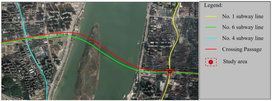
Figure 1.
The overall direction and distribution of the project.
The foundation pit is approximately 7.6 m deep, 21.3 m wide and 41.3 m long. The enclosure structure adopts the support form of an underground diaphragm wall with internal support, and the thickness of the underground diaphragm wall is 1.0 m. The construction is carried out by the open excavation method. The average distance between the base plate of the upper span structure of the channel across the river and the vault of the shield tunnel of Line 1 is 2.7 m, and the minimum distance is only 2.6 m. The base is located in the powder clay layer, and the existing tunnel is located in the medium weathered slate stratum, which is approximately orthogonal to the long axis of the foundation pit. The outer diameter D of the tube sheet of the existing tunnel is 6.0 m and the thickness is 0.3 m. The reinforced concrete tube sheet of C30 strength is used. One ring consists of a capping block, two adjacent blocks, two standard blocks and one bottom block, with 10 longitudinal connection bolts. The relationship between the excavation area and the existing tunnel location is shown in Figure 2.
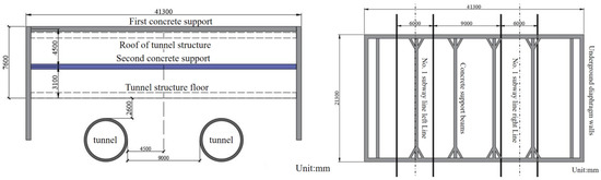
Figure 2.
Relationship between foundation pit and existing tunnel location.
According to the surface exposure and the disclosure of preliminary drilling survey, the stratum within the pit area is mainly composed of quaternary artificially deposited soil, lacustrine material, river alluvium and residual powder clay. The underlying bedrock is the Middle Yuangujie Slate Group and Lengjiaxi Group Slate. Table 1 shows the proposed values of geotechnical material parameters. The formation parameters in Table 1 are determined according to the geological survey report and laboratory experiments.

Table 1.
Measured values of mechanical parameters of engineering geotechnical materials.
During the survey, no groundwater was encountered in the borehole of this pit node site. The foundation excavation stratum is mainly powder clay, and its permeability coefficient is only 0.001 m/d, so the permeability is very low. Therefore, there is less precipitation in this foundation excavation project, and the influence of foundation precipitation is negligible in theoretical calculation and numerical simulation.
3. The Foundations of Theory Calculation
The excavated soil will cause additional stresses in the surrounding soil, which will eventually cause deformation in the surrounding soil and existing structures. Therefore, when studying the effect of foundation excavation on existing tunnels, the magnitude and distribution of the unloading loads caused by foundation excavation should be determined first. Then, the additional stresses in the existing tunnel caused by the unloading loads are determined, and the deformation of the tunnel is finally determined by combining the displacement coupling equation.
A two-stage approach is commonly used for the theoretical calculation of the deformation of the adjacent tunnel caused by the foundation excavation [18,19]. The first stage uses conventional mechanical methods to determine the additional stresses in the existing tunnel caused by the excavation of the pit. The Mindlin solution or the elastodynamic method is generally used. In the second stage, the additional stress distribution is applied to the existing tunnel based on the magnitude of the additional stresses determined in the first stage. Based on some theoretical models such as the elastic foundation beam, the existing tunnel is considered as a continuous beam buried in the soil. Combining the deformation coupling conditions between the soil and the tunnel, the deformation of the existing tunnel caused by the foundation excavation is finally calculated.
3.1. Calculation of Additional Stress
Mindlin [20] derived a formula to calculate the additional stress at any point caused by a unit vertical load or horizontal load at a point in a semi-infinite space based on theories such as elastic mechanics. Figure 3 shows the computational model of Mindlin’s solution, where the coordinates of the unit load point are (x,y,z) and the coordinates of any point are (x0,y0,z0).
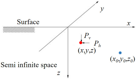
Figure 3.
Simplified presentation of the Mindlin calculation.
The point (x0,y0,z0) under the action of the horizontal load Ph to cause another point of vertical deformation w1 calculation formula:
The point (x0,y0,z0) under the action of the vertical load Pv to cause another point of vertical deformation w2 calculation formula:
where G is the shear modulus of the soil; μ is Poisson’s ratio of soil mass. R1 = [(x − x0)2 + (y − y0)2 + (z − z0)2]1/2, R2 = [(x − x0)2 + (y − y0)2 + (z + z0)2]1/2.
3.2. Model of Foundation Sloping
According to the previous analysis process, the magnitude and distribution width of the unloading load after the sloping excavation of the foundation pit must be determined first. There are usually two forms of sloping excavation: excavating the middle soil and reserving the core soil on both sides or excavating on both sides and reserving core soil the middle, as shown in Figure 4. In this figure, H is the excavation depth of the pit, (m); L is the excavation width of the pit, (m); θ is the angle of the foot of the slope of the sloping excavation, (°); b is the excavation width of the sloping excavation body, (m); b1 is the width of the bottom of the pit of the sloping excavation body, b1 = b + Hcotθ, b2 = b − Hcotθ, (m). The numbers 1, 2 represent the order of excavation.
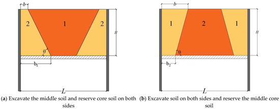
Figure 4.
Load calculation schematic diagram of the proposed sloping excavation.
The vertical unloading loads of the two sloping excavation methods can be calculated from the density and volume of the excavated soil. The action position is still assumed to be at the bottom of the foundation pit. However, there is no research on the range and width of unloading load after sloping excavation. For the method of excavating the middle soil and reserving the core soil on both sides, the soil in the middle of the pit is excavated first. In this paper, the width of the unexcavated soil body’s load distribution is the top edge of the trapezoid, the bottom edge of the trapezoid and the middle line of the trapezoid, respectively. The corresponding unloading distribution widths are la1 = L − 2b, la2 = L − 2b − 2Hcotθ, la3 = L − 2b − Hcotθ. For Figure 4a, the unloading load magnitude for the three load distribution width cases are formulated as follows:
where γ is the soil weight, (N/m3) and α is the residual stress coefficient.
For the three load distribution cases using the method of excavating soil on both sides and reserving the middle core soil in Figure 4b, the proposed unloading load distribution widths are lb1 = b, lb2 = b2, lb3 = (b + b2)/2. The size of the unloading load is determined as follows:
For the method of excavating the middle soil and reserving the core soil on both sides, Figure 5 shows the calculation diagram of the lateral unloading load.

Figure 5.
Lateral unloading load calculation diagram.
For the excavation method of reserving core soil on both sides, the unloading effect on the sides is basically very small because the enclosure structure is applied on both sides and there are retained soil bodies on both sides. Therefore, our study assumes that there is no consideration of unloading effects on sides 2 and 3. After the excavation of the middle soil, the free face will be formed at sides 4 and 5. Considering the restraint of the deformation of the underground diaphragm wall by the sloping soil on both sides, the width of the unloading surface is assumed as l = (L − 2b − 2Hcotθ) in this study for sides 4 and 5. The unloading load magnitude of the lateral sides is calculated as
where a is the unloading discount factor considering the role of the support structure, which generally takes the value of 0.1–0.3. When considering the most adverse effect, it takes a value of 0.5.
For the method of excavating soil on both sides and reserving the middle core soil, Figure 6 shows the calculation diagram of lateral unloading load.
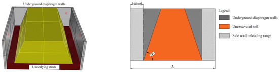
Figure 6.
Lateral unloading load calculation diagram.
When the soil on both sides is excavated, four free faces are exposed. The unloading load calculation method for sides 2 and 3 is the same as the previous section. For the unloading load calculation of side 4, the unloading load distribution width is assumed as l = (b − Hcotθ) considering the deformation restraint effect of the unexcavated soil in the middle on the underground diaphragm wall. The magnitude of the unloading load on the side is calculated by the formula:
3.3. Excavate the Middle Soil and Reserve Core Soil on Both Sides
The unloading load magnitude and distribution range analyzed above can be substituted into Mindlin’s solution. In the method of excavation that excavates the middle soil and reserves the core soil on both sides, the additional load stress caused by the unloading of the foundation is calculated as follows:
where q is taken as qa1, qa2, qa3, la1 = L − 2b, la2 = L − 2b − 2Hcotθ, la3 = L − 2b − Hcotθ, respectively, and the other symbols are taken as before.
For pit sides 4 and 5, the additional positive stresses in the existing tunnel caused by the unloading load are calculated as follows:
3.4. Excavate on Both Sides Soil and Reserve the Middle Core Soil
Because the unloading load is symmetrically distributed on both sides in the method of excavating soil on both sides and reserving the middle core soil, the integration process can simplify the load to twice the original load. Its basement unloading triggered additional load stress calculation formula, which is:
where q is taken as qb1, qb2, qb3, lb1 = b, lb2 = b2, lb3 = (b + b2)/2, respectively. For the pit sides 2 and 3, the magnitude of the additional stress induced by its unloading load is calculated by the formula:
For pit sides 4 and 5, the magnitude of the additional stress induced by the unloading load is calculated as, which is:
3.5. Calculation of Existing Tunnel Deformation
The additional stress caused by the excavation of the foundation pit will definitely cause the surrounding soil and the existing subway tunnel line to deform at the same time. In this case, the tunnel will interact with the surrounding soil. The Winkler and Euler models ignore the shear effect of the tunnel and the soil, which is different from the actual situation, and the Pasternak model takes into account the shear strength of the soil and has fewer variables in the relationship equation [21,22,23]. Therefore, it is often used in the calculation of tunnel deformation caused by unloading, and the Pasternak foundation beam model is also used in this study. The calculation model of the coupling between the existing tunnel and the soil is shown in Figure 7.
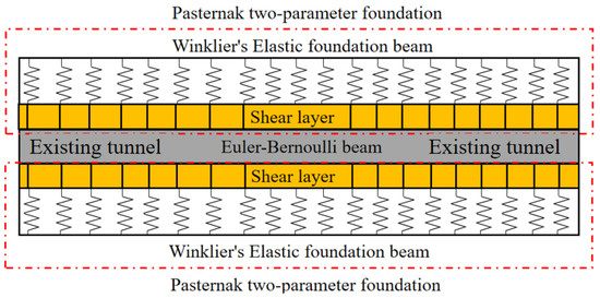
Figure 7.
Pasternak foundation beam model.
The Pasternak two-parameter foundation consists of Winklier’s elastic foundation beam and the soil shear layer, and the deflection differential equation of Pasternak two–parameter foundation can be expressed as follows [24,25]:
where q(z) is the additional load on the existing tunnel; and d and EI are the width and bending stiffness of the existing pipeline, respectively. The accuracy of the EI will affect the accuracy of the calculation results. However, the value of the tunnel EI is still not clear at this stage. In our study, the discount factor method is used to calculate the tunnel flexural stiffness EI based on the calculation method of tunnel flexural stiffness EI; k is the stiffness of Winklier’s elastic foundation beam [26], and Gc is the stiffness of the shear layer, which is calculated as follows [27,28]:
where Et and μ are the elastic modulus and Poisson’s ratio of the soil, respectively, Et = 1.3~5.0 Es; Es is the compression modulus of the soil; ht is the thickness of the shear layer related to the soil characteristics, and ht is typically considered to be 2.5 times equal to the pipe diameter.
Equation (21) is a high-order differential equation, and is difficult to analyze using conventional calculation methods. The finite difference method is one of the most important tools for solving high-order differential equations. The continuous tunnel is discretized into 2N + 5 elements, and each element length is equals to t. This includes 2N + 1 elements within the calculation range and two virtual elements on each side of the calculation range. The displacement magnitude of each element is determined by the boundary conditions and the coordination of the displacements between the elements. Figure 8 shows the discretized existing tunnel.
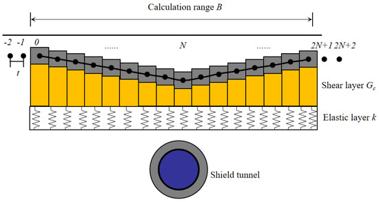
Figure 8.
Discrete model of the tunnel.
According to the finite difference equation, the high-order differential equation can be transformed into:
The locations (point 0 and point N) on the boundary of the calculation range B are considered to be unaffected by the excavation of the shield tunnel. The bending moment M and the shear force Q at the corresponding points are equal to 0. Accordingly, we fit the following:
Combining the boundary conditions and the finite difference equation, the displacement expressions for the four virtual nodes outside the calculation range B can be obtained as:
Based on Equations (24) and (26), iterative operations can determine the displacement relationship of all elements after discretization. Substituting it into Equation (21), then 2N + 1 sets of equations can be obtained, and the corresponding sets of equations are transformed into matrix vectors as follows:
where [q(z)]2N+1 is the additional load matrix acting on the discrete element; [k]2N+1 is the soil bed coefficient matrix; [G]2N+1 is the shear layer stiffness matrix; [K]2N+1 is the tunnel stiffness matrix; and [wG(z)]2N+1 is the deformation matrix of the discrete element.
Equations (28)–(30) and the calculated parameters are substituted in Equation (27) to obtain the deformation considering the coupling between the existing tunnel and the soil.
4. Validation of the Numerical Simulation
4.1. Calculation and Element Parameters
In order to verify the correctness of the theoretical formulation by comparison, a model of the pit excavation was constructed using the finite difference software FLAC3D. The excavation area of the foundation pit is 41.3 × 22.0 × 7.6 m. The distance between the existing metro line and the foundation is 3.0 m. The support structure is in the form of an underground diaphragm wall with internal bracing, with a wall thickness of 1.0 m and an embedded depth of 10.0 m. The support structure has a high stiffness. The tube sheet of the existing tunnel has an external diameter D of 6.0 m and a thickness of 0.3 m. A reinforced concrete tube sheet of C40 strength was used. According to the available research, the unloading index of the pit sidewall is taken as a = 0.2, assuming that the soil is homogeneous in the calculation model, and the soil parameters are the weighted average of the parameters of different soil layers within the excavation area of the pit. The Mohr–Coulomb elastoplastic model was selected as the constitutive relation of soil, and soil parameters of each layer were determined according to the engineering investigation report. The linear elastic model was adopted for the diaphragm wall and existing tunnel segment [29,30]. Table 2 shows the values of each theoretical calculation parameter and numerical simulation material.
Table 2.
Values of the theoretical calculation parameters.
4.2. Modeling and Calculation Steps
Aiming to reduce the influence of the numerical model boundary conditions on the calculation results, the model size should be at least three times the size of the pit [31]. Therefore, the model size of this study is 164 × 100 × 40 m. The model is fully meshed with a hexahedral mesh, with 112,205 mesh elements and 99,958 nodes. The boundary conditions of the model are to constrain the normal displacement of the front, rear, left and right and the bottom surface. The constructed numerical model is shown in Figure 9.
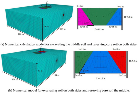
Figure 9.
Our proposed numerical calculation model.
4.3. Results Analysis of Numerical Simulation
The excavation of the pit will mainly lead to vertical deformation at the top of the tunnel vault and horizontal deformation at the arch waist. Due to page limitations, the results are analyzed only for vertical deformation at the vault and horizontal deformation at the arch waist.
4.3.1. Excavate the Middle Soil and Reserve Core Soil on Both Sides
Figure 10 shows a cloud diagram of the vertical deformation of the tunnel caused by the method of excavating the middle soil and reserving core soil on both sides and the vertical deformation curve at the vault.
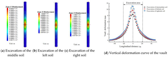
Figure 10.
Vertical deformation of the tunnel.
In Figure 10, the first step excavated the soil directly above the existing tunnel, resulting in the significant vertical deformation of the tunnel, with a maximum deformation of 8.6 mm, located at the central position of the pit. The vertical deformation only slightly increased with the subsequent excavation of the left and right sides of the tunnel. The final deformation was 11.3 mm, a difference of only 2.7 mm from the first step, which means that it is the soil above the tunnel that affects the deformation of the existing tunnel, while the surrounding soil has less influence on it. The maximum vertical deformation of the existing tunnel was 15.1 mm when the block excavation method was used. The maximum vertical deformation of the existing tunnel was reduced by 25% with the sloping method compared to the block excavation method.
In Figure 11, the method of excavating the middle soil and reserving the core soil on both sides does not lead to a shift in the maximum position of the horizontal deformation of the arch waist. After the excavation of the middle soil, the horizontal deformation at the arch waist reaches its maximum value, with a maximum horizontal deformation of 3.07 mm. After the excavation of the soil on both sides, the horizontal deformation of the arch waist changes to a lesser extent.
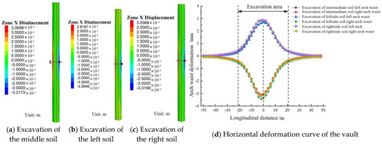
Figure 11.
Graphical presentation of the horizontal deformation of the tunnel.
4.3.2. Excavating Soil on Both Sides and Reserving the Middle Core Soil
Figure 12 shows the vertical deformation cloud diagram and the vault bulge curve for the excavation method of excavating soil on both sides and reserving the middle core soil. The maximum vertical deformation of the vault is located on the right side of the existing tunnel, with a maximum deformation of 0.96 mm. After the excavation of the left side, the maximum position is shifted slightly away from the central position of the tunnel, with a maximum deformation of 1.5 mm. The excavation of the left and right sides of the soil has a minimal impact on the deformation of the existing tunnel. After excavating the middle core soil, the maximum deformation of the existing tunnel is reached, with a maximum deformation of 8.8 mm, located at the central position of the tunnel. After the excavation of the middle core soil, the tunnel deformation increased by 486% compared to the previous two excavation steps. This proves that the soil located directly above the existing tunnel is the main factor causing vertical deformation in the existing tunnel. The maximum vertical deformation was reduced by 44% compared to the block excavation method. The maximum vertical differential settlement value for the existing tunnel within the pit excavation is 0.035% and the differential settlement rate within the pit excavation is reduced by 63%. This indicates that the use of excavating soil on both sides and reserving core soil in the middle is effective for reducing the impact of unloading of the foundation excavation on the existing tunnel.
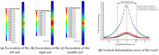
Figure 12.
Graphical presentation of the vertical deformation of the tunnel.
Figure 13 shows the horizontal deformation cloud and the horizontal deformation curve at the arch waist caused by the method of excavating soil on both sides and reserving the middle core soil.
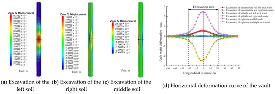
Figure 13.
Graphical presentation of the horizontal deformation of the tunnel.
In Figure 13, the excavation of the right side of the soil shows an overall rightward deformation of the existing tunnel. After excavating the left side of the soil, the horizontal deformation of the arch waist on the left and right side shows a symmetrical distribution. The deformation values at this stage were small, with a maximum deformation of 0.1 mm. After the excavation of the middle soil, the horizontal deformation of the existing tunnel increases enormously, with a maximum deformation of 2.5 mm. The horizontal deformation of the arch waist on the left and right sides is symmetrically distributed. The soil directly above the tunnel is still the main factor determining the horizontal deformation of the tunnel, in consistency with the factors influencing the vertical deformation of the tunnel. This shows that reserving the core soil above the existing tunnel can significantly reduce the impact of the excavation on the tunnel. The method of excavating soil on both sides and reserving the middle core soil reduces the horizontal deformation of the existing tunnel by 50% compared to the block excavation method.
The comparison between the above two excavation methods shows that when the existing tunnel is a single-line tunnel, the excavation disturbance of the existing tunnel line caused by using the method excavating on both sides and reserving core soil the middle is less than that caused by the method of excavating the middle soil and reserving core soil on both sides. Therefore, when the pit excavation is close to the existing tunnel line, the soil can be first excavated away from the tunnel.
4.4. Comparative Analysis of Calculation Results
4.4.1. Excavate the Middle Soil and Reserve Core Soil on Both Sides
In the theoretical calculations, the method of excavating the middle soil and reserving core soil on both sides only considers the effect of excavating the middle soil, and the effect of subsequent excavation on both sides of the soil is not considered. By substituting the calculation parameters in Table 2 into Equations (1)–(4), the vertical loads on the substrate for the three unloading load distribution widths are 10,919 kPa, 15,044 kPa and 10,760 kPa, for excavating the middle soil and reserving core soil on both sides. The widths of the distribution of the substrate unloading effects are 36.0 m, 26.1 m and 31.0 m, respectively. The horizontal unloading load on the sidewall is 2084 kPa and the sidewall unloading load is distributed over a width of 26.1 m. By substituting the above calculation parameters into Equations (10)–(13), the vertical additional stress at the top of the existing tunnel vault and the horizontal additional stress at the arch waist caused by the excavation of the middle soil are calculated. Based on the two-stage method in Chapter 2, calculations were carried out to obtain the vertical deformation of the existing tunnel vault and the horizontal deformation of the arch waist caused by the excavation of the middle soil for the method of excavating the middle soil and reserving the core soil on both sides as shown in Figure 14.
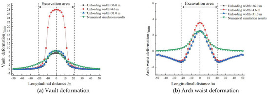
Figure 14.
Comparison of the theoretical calculations (when excavating the middle soil and reserving the core soil on both sides).
In Figure 14, the calculation results have the fewest errors with the numerical simulation results when the unloading strength of the substrate is 917 kPa and the unloading width is 31.0 m. This shows that the results are most accurate when the unloading width is calculated by taking the length of the central line of the slope trapezoid for the sloping excavation method, which uses the method of excavating the middle soil and reserving core soil on both sides. Taking the unloading width as the short side of the trapezoid of the sloping excavation will result in a very high level of error in the calculation results. The main reason for this is that taking the short side of the trapezoid for the unloading width will result in a significant increase in load strength. The results of the theoretical calculations are consistent with the results obtained from the numerical simulations. The use of a sloping excavation method can significantly reduce the deformation of the existing tunnel.
4.4.2. Excavate on Both Sides Soil and Reserve the Middle Core Soil
In the theoretical calculations, the method of excavating soil on both sides and reserving the middle core soil only considers the effect of excavating the soil on both sides and does not consider the effect of the subsequent excavation of the soil in the middle. The vertical load magnitudes for the three unloading load distribution widths are 23,063 kPa, 8719 kPa and 12,654 kPa, respectively. The distributional width of the unloading action is 3.0 m, 7.9 m and 5.5 m, respectively. The horizontal unloading load on the sidewall is 2084 kPa and the width of the load distribution for the unloading of the sidewall is 3.0 m.
The calculations were carried out to obtain the vertical deformation of the vault of the existing tunnel and the horizontal deformation of the arch waist caused by the excavation of the soil on both sides of the method of excavating soil on both sides and reserving the middle core soil, as shown in Figure 15.
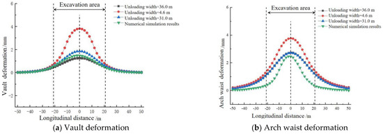
Figure 15.
Comparison of the theoretical calculations (the method of excavating soil on both sides and reserving the middle core soil).
In Figure 15, the theoretical results are very close to the results of the numerical simulations. Unlike the results of the calculation for the method of excavating the middle soil and reserving the core soil on both sides, for the method of excavating soil on both sides and reserving the middle core soil, the minimum error with the numerical simulation results is the way in which the unloading action is at 3.0 m width and the unloading load strength is 10,919 kPa with its three load distribution cases. This means that the calculated load distribution width is chosen to be the trapezoidal short side of the slope. However, the calculation results based on the trapezoidal central line of the slope are also less inaccurate than the numerical simulation results. Therefore, it is also possible to calculate the load distribution width as the length of the trapezoidal central line of the slope. After the excavation of the soil on both sides, the removal of the soil has a very low impact on the existing tunnel. It also proves that when excavating large volumes of soil close to an existing tunnel, the soil can be excavated away from the existing tunnel side first. The excavation provides a working surface for reinforcement or counter-pressure measures, thus ultimately ensuring the safety and stability of the subsequent construction.
By comparing the numerical simulations with the theoretical solution, the unloading width is most reasonably taken to be the length of the slope central line when adopting sloping excavation. The smaller excavation area and the lower unloaded load levels in the one-time excavation reduce the deformation of the tunnel. According to the above analysis, the results of the formulae derived in our study are less inaccurate than the results of the numerical simulations. This proves the applicability of the formulae derived in this study.
5. Parametric Analysis
On the basis of the previous study, the effect of each design factor on the disturbance of existing tunnels was studied. The main factors related to the sloping excavation are the foot of slope θ, the depth of excavation H and the width of the slope b. In this study, the above three main factors are analyzed separately, using the method of excavating the middle soil and reserving the core soil on both sides as the research solution. Due to the page limitations, this section analyses the effect of the different factors on tunnel deformation only in comparison to existing tunnel vertical bulge deformation.
5.1. Different Footings of the Slope
The values of θ for different footings of the slope and the relative strength and distribution of the unloading loads are shown in Table 3.
Table 3.
Unloading loads and distribution range for different footings of slope θ.
The deformation of the existing tunnel vault decreases with the foot of the slope in Figure 16. As the foot of the slope slows down, the width of the unloaded load decreases for the same excavation depth and slope width, but the load strength also decreases. However, the effect of the load strength on the deformation of the tunnel structure is clearly greater than the effect on the load distribution. This leads to a situation where the deformation of the tunnel structure decreases with the degree of slope at the foot of the slope. Practically, the foot of the slope can be reduced to meet the needs of the safety of the slope and the construction work surface.
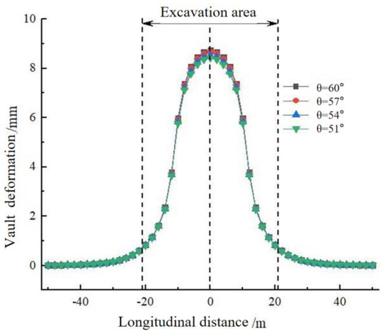
Figure 16.
Calculated results for the different footings of the slope θ.
5.2. Different Slope Widths
The values of the different slope widths b and the relative strength and distribution of the unloading loads are shown in Table 4.
Table 4.
Various slope widths b, loads and range of effects.
In view of the different slope widths b, Figure 17 shows the deformation of the vault. As the slope width b decreases, the extent of the vault deformation increases. An increase in the slope width will lead to a decrease in the unloading load and the width of the load distribution, which consequently reduces the deformation of the existing tunnel vault.
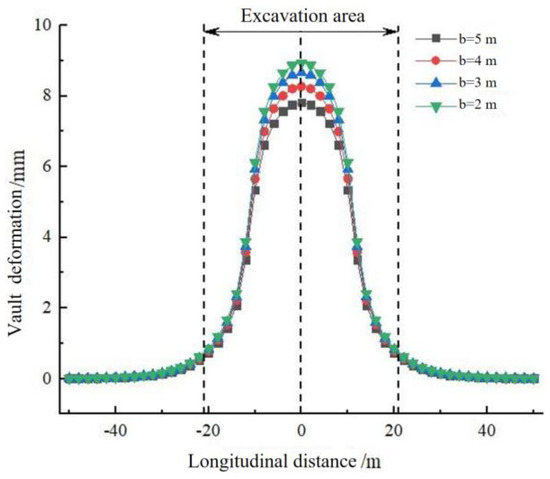
Figure 17.
Calculation results for the different slope widths b.
5.3. Excavation Depths
The values of the different excavation depths H and the relative unloading load strengths and distribution ranges are shown in Table 5.
Table 5.
Unloading loads and ranges of effects for different excavation depths H.
The vault deformation for the different excavation depths H is shown in Figure 18. Changes in the excavation depth have a significant impact on the deformation of the existing tunnel vault. As the excavation depth decreases, the vertical deformation of the existing tunnel becomes smaller and smaller. The reduction in the excavation depth significantly decreases the loads, which in turn reduces the disturbance to the existing tunnel and protects the existing tunnel. This is in accordance with the pattern of the effect of the depth on tunnel deformation during the construction of the block excavation. Practically, large excavation depths at one time should be limited to avoid damage to existing tunnels caused by excessive unloading.
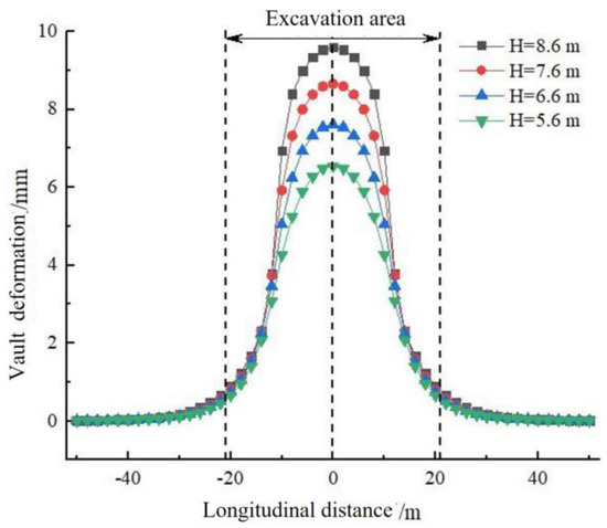
Figure 18.
Calculated results for the different excavation depths H.
6. Conclusions
(1) Compared with the block excavation method with the same excavation depth, the sloping excavation method reduces the unloading strength of the excavation and decreases the deformation of the existing tunnel during the excavation. The maximum vertical deformation of the tunnel was reduced by 25% and 43%, respectively, by the method of excavating the middle soil and reserving core soil on both sides, the method of excavation soil on both sides and reserving the middle core soil.
(2) During the pit excavation, the main deformation of the existing tunnel was caused by the soil directly above the tunnel, while the soil around the tunnel had less influence on it. In the case of the foundation pit spanning a single-line existing tunnel, the sloping excavation method for excavating soil on both sides and reserving the middle core soil can be used. For the foundation pit spanning a double-lane tunnel, the sloping excavation method of excavating the middle soil and reserving the core soil on both sides can be used.
(3) Theoretical calculation results have a small error with the numerical simulation results, verifying the correctness of the theoretical calculation results. For the foundation pit project using sloping excavation, the width of the load distribution of the soil after excavation can be taken as the width of the median line. This approach produces the lowest calculation error.
(4) With the sloping excavation method, the deformation of the existing tunnel is significantly affected by the changes in the one-time excavation depth H and the slope width b, but less by changes in the slope angle θ. In practice, it is possible to reduce the depth of the one-time excavation and increase the width of the slope in order to minimize the disturbance to the existing tunnel, while ensuring the stability of the slope and the need for a working surface.
Author Contributions
H.-L.F.: Methodology, Software, Data processing, Writing—original draft. H.-S.D.: Conceptualization, Methodology, Supervision, Project administration. Y.-B.Z.: Validation, Formal analysis, Writing—review and editing. X.-B.C.: Validation, Formal analysis, Writing—review and editing. H.-D.Y.: language problem check. All authors have read and agreed to the published version of the manuscript.
Funding
This study was financially supported by the National Natural Science Foundation of China (Grant Nos. 51538009, 51978668).
Institutional Review Board Statement
Not applicable.
Informed Consent Statement
Not applicable.
Data Availability Statement
Not applicable.
Acknowledgments
The authors thank the Advanced Research Center, Central South University, for providing the experiment conditions. The authors also express special thanks to the editors and anonymous reviewers for their constructive comments.
Conflicts of Interest
The authors declare that they have no known competing financial interests or personal relationships that could have appeared to influence the work reported in this paper.
References
- Festa, D.; Broere, W.; Bosch, J.W. Tunnel-boring in soft soil: A study on the driving forces applied to a slurry-shield TBM. Civ. Eng. Geosci. 2012. Available online: https://www.researchgate.net/profile/Wout-Broere/publication/328981655_Tunnel-boring_in_soft_soil_a_study_on_the_driving_forces_applied_to_a_slurry-shield_TBM/links/5bee9b28a6fdcc3a8dda1a40/Tunnel-boring-in-soft-soil-a-study-on-the-driving-forces-applied-to-a-slurry-shield-TBM.pdf (accessed on 1 December 2022).
- Cheng, H.; Chen, J.; Chen, G. Analysis of ground surface settlement induced by a large EPB shield tunnelling: A case study in Beijing, China. Environ. Earth Sci. 2019, 78, 605. [Google Scholar] [CrossRef]
- Di, H.; Huang, S.; Fu, L.; Wang, B. A variational method for calculating the longitudinal deformation of a shield tunnel in soft soil caused by grouting under tunnel. Eng. Comput. 2021, 38, 2733–2754. [Google Scholar] [CrossRef]
- Liang, R.; Wu, W.; Yu, F.; Jiang, G.; Liu, J. Simplified method for evaluating shield tunnel deformation due to adjacent excavation. Tunn. Undergr. Space Technol. 2018, 71, 94–105. [Google Scholar] [CrossRef]
- Liu, J.; Shi, C.; Lei, M.; Cao, C.; Lin, Y. Improved analytical method for evaluating the responses of a shield tunnel to adjacent excavations and its application. Tunn. Undergr. Space Technol. 2020, 98, 103339. [Google Scholar] [CrossRef]
- Zhang, Z.; Huang, M.; Zhang, C.; Jiang, K.; Lu, M. Time-domain analyses for pile deformation induced by adjacent excavation considering influences of viscoelastic mechanism. Tunn. Undergr. Space Technol. 2019, 85, 392–405. [Google Scholar] [CrossRef]
- Shi, C.; Cao, C.; Lei, M.; Peng, L.; Ai, H. Effects of lateral unloading on the mechanical and deformation performance of shield tunnel segment joints. Tunn. Undergr. Space Technol. 2016, 51, 175–188. [Google Scholar] [CrossRef]
- Liu, H.; Li, P.; Liu, J. Numerical investigation of underlying tunnel heave during a new tunnel construction. Tunn. Undergr. Space Technol. 2011, 26, 276–283. [Google Scholar] [CrossRef]
- Li, M.-G.; Zhang, Z.-J.; Chen, J.-J.; Wang, J.-H.; Xu, A.-J. Zoned and staged construction of an underground complex in Shanghai soft clay. Tunn. Undergr. Space Technol. 2017, 67, 187–200. [Google Scholar] [CrossRef]
- Zhao, X.; Wang, H.; Li, Z.; Dai, G.; Yin, Z.; Cao, S.; Zhou, J. Numerical Study on the Deformation of Tunnels by Excavation of Foundation Pit Adjacent to the Subway. Appl. Sci. 2022, 12, 4752. [Google Scholar] [CrossRef]
- Sun, H.; Wang, L.; Chen, S.; Deng, H.; Zhang, J. A precise prediction of tunnel deformation caused by circular foundation pit excavation. Appl. Sci. 2019, 9, 2275. [Google Scholar] [CrossRef]
- Nejjar, K.; Dias, D.; Cuira, F.; Chapron, G.; Lebissonnais, H. Experimental study of the performance of a 32 m deep excavation in the suburbs of Paris. Géotechnique 2021, 1–11. [Google Scholar] [CrossRef]
- Mitew-Czajewska, M. A study of displacements of structures in the vicinity of deep excavation. Arch. Civ. Mech. Eng. 2019, 19, 547–556. [Google Scholar] [CrossRef]
- Soomro, M.A.; Liu, K.; Mangnejo, D.A.; Mangi, N. Effects of twin excavations with different construction sequence on a brick masonry wall: 3D finite element approach. Structures 2022, 41, 866–886. [Google Scholar] [CrossRef]
- Deng, H.; Fu, H.; Shi, Y.; Huang, Z.; Huang, Q. Analysis of Asymmetrical Deformation of Surface and Oblique Pipeline Caused by Shield Tunneling along Curved Section. Symmetry 2021, 13, 2396. [Google Scholar] [CrossRef]
- Zhang, W.; Li, Y.; Wu, C.; Li, H.; Goh, A.; Liu, H. Prediction of lining response for twin tunnels constructed in anisotropic clay using machine learning techniques. Undergr. Space 2020, 7, 122–133. [Google Scholar] [CrossRef]
- Pang, R.; Xu, B.; Zhou, Y.; Song, L. Seismic time-history response and system reliability analysis of slopes considering uncertainty of multi-parameters and earthquake excitations. Comput. Geotech. 2021, 136, 104245. [Google Scholar] [CrossRef]
- Liang, R.; Kang, C.; Xiang, L.; Li, Z.; Lin, C.; Gao, K.; Guo, Y. Responses of in-service shield tunnel to overcrossing tunnelling in soft ground. Environ. Earth Sci. 2021, 80, 183. [Google Scholar] [CrossRef]
- Zhang, Z.; Zhang, M.; Zhao, Q. A simplified analysis for deformation behavior of buried pipelines considering disturbance effects of underground excavation in soft clays. Arab. J. Geosci. 2015, 8, 7771–7785. [Google Scholar] [CrossRef]
- Mindlin, R.D. Force at a Point in the Interior of a Semi-Infinite Solid. Physics 1936, 7, 195–202. [Google Scholar] [CrossRef]
- Zhang, Z.; Zhang, M. Mechanical effects of tunneling on adjacent pipelines based on Galerkin solution and layered transfer matrix solution. Soils Found. 2013, 53, 557–568. [Google Scholar] [CrossRef]
- Lin, C.; Huang, M.; Nadim, F.; Liu, Z. Embankment responses to shield tunnelling considering soil-structure interaction: Case studies in Hangzhou soft ground. Tunn. Undergr. Space Technol. 2019, 96, 103230. [Google Scholar] [CrossRef]
- Zhou, R.; Fang, W.; Wu, J. A risk assessment model of a sewer pipeline in an underground utility tunnel based on a Bayesian network. Tunn. Undergr. Space Technol. 2020, 103, 103473. [Google Scholar] [CrossRef]
- Ma, S.; Li, M.; Jin, J.; Bai, K. The influence of shallow buried double-line parallel rectangular pipe jacking construction on ground settlement deformation. Alex. Eng. J. 2021, 60, 1911–1916. [Google Scholar] [CrossRef]
- Zhang, J.; Xie, R.; Zhang, H. Mechanical response analysis of the buried pipeline due to adjacent foundation pit excavation. Tunn. Undergr. Space Technol. 2018, 78, 135–145. [Google Scholar] [CrossRef]
- Tanahashi, H. Formulas for an Infinitely Long Bernoulli-Euler Beam on the Pasternak Model. Soils Found. 2004, 44, 109–118. [Google Scholar] [CrossRef]
- Zhang, D.-M.; Huang, Z.-K.; Li, Z.-L.; Zong, X.; Zhang, D.-M. Analytical solution for the response of an existing tunnel to a new tunnel excavation underneath. Comput. Geotech. 2019, 108, 197–211. [Google Scholar] [CrossRef]
- Vorster, T.E.; Klar, A.; Soga, K.; Mair, R.J. Estimating the Effects of Tunneling on Existing Pipelines. J. Geotech. Geoenviron. Eng. 2005, 131, 1399–1410. [Google Scholar] [CrossRef]
- Chheng, C.; Likitlersuang, S. Underground excavation behaviour in Bangkok using three-dimensional finite element method. Comput. Geotech. 2018, 95, 68–81. [Google Scholar] [CrossRef]
- Goh, A.; Zhang, F.; Zhang, W.; Zhang, Y.; Liu, H. A simple estimation model for 3D braced excavation wall deflection. Comput. Geotech. 2017, 83, 106–113. [Google Scholar] [CrossRef]
- Deng, H.-S.; Fu, H.-L.; Shi, Y.; Zhao, Y.-Y.; Hou, W.-Z. Countermeasures against large deformation of deep-buried soft rock tunnels in areas with high geostress: A case study. Tunn. Undergr. Space Technol. 2022, 119, 104238. [Google Scholar] [CrossRef]


Disclaimer/Publisher’s Note: The statements, opinions and data contained in all publications are solely those of the individual author(s) and contributor(s) and not of MDPI and/or the editor(s). MDPI and/or the editor(s) disclaim responsibility for any injury to people or property resulting from any ideas, methods, instructions or products referred to in the content. |
© 2023 by the authors. Licensee MDPI, Basel, Switzerland. This article is an open access article distributed under the terms and conditions of the Creative Commons Attribution (CC BY) license (https://creativecommons.org/licenses/by/4.0/).