1. Introduction
A high-speed permanent magnet motor has a sound momentum of growth [
1], and its application areas involve aerospace [
2,
3], new energy vehicles, high-speed turbomachinery, industrial machinery [
4], intelligent agriculture [
5], etc. This is due to their small size and light weight while achieving high-density power and the maximum satisfaction of working conditions [
6,
7]. The development of a high-speed permanent magnet motor follows the trend of lightweight technology. The application area will be fully popular and covered in the future when the technology becomes more mature [
8].
In motors, the compressive strength of permanent magnets is much greater than the tensile strength; therefore, permanent magnets and alloy steel sheath are generally assembled by interference fit [
9]. In the interference fit, the interference value is one of the key factors that affects the rotation of the high-speed motor [
10]. If the interference value is too large, the magnet will collapse. In the process of high-speed rotation, the actual interference value is less than the static value. If the interference value is too small, it will easily cause the sheath to fall off. On the one hand, the magnet cannot be protected; on the other hand, it will cause the safety problem of falling off and splashing [
11].
A high-speed permanent magnet motor is the core driving component of a centrifugal air compressor. The power of the centrifugal air compressor is output by the motor. Energy conversion is transmitted to the impeller through the motor. Its safety and reliability are embodied in the stability of the rotor structure, which greatly affects the stability and working efficiency of the centrifugal air compressor. This paper focuses on the rotor system of aero-dynamic bearing in the centrifugal compressor. Through simulation, the stress of the magnet and sheath of a high-speed permanent magnet motor under the interference fit is explored, and the factors of rotor strength are analyzed [
12,
13,
14].
Gan et al. [
15] analyzed the critical speed, unbalance response, and stability of the shaft system in detail, and they proposed an investigation scheme of the rotor strength and rotor dynamic characteristics for high-speed and high power switched reluctance machines (SRMs). On the basis of rotor strength constraint, Xu et al. [
16] presented the composite sheath of a high-speed permanent magnet generator to make the stress distribution reasonable and reduce eddy current loss. Shao et al. [
17] analyzed the influences of static interference and the thickness of sleeve and sleeve material on the rotor strength and summarized the strength design rules of an ultra-high-speed permanent magnet synchronous rotor. A lot of research mainly focuses on the influence of parameters, and research on the variation in the interference structure is insufficient. According to the simulation results of stress, we adopt a method which adds chamfer to the end covers of the magnet to reduce the maximum principal stress. This method can reduce the probability of permanent magnet collapse.
The heating condition of an ordinary motor may be relatively low, but the heating condition of a high-speed motor is serious due to the higher speed and greater power. The temperature has a great impact on the stability of a high-speed motor [
18,
19,
20]. It is valuable to focus on the relationship between temperature and rotor strength of a high-speed motor. It has been found that most studies focusing on the rotor strength of the interference fit and temperature only analyze the relationship between stress and temperature under one simple interference condition. Chen et al. [
21] simplified the rotor stress condition as a plane stress problem, and the analytical formulae for rotor strength was proposed based on the displacement method in polar coordinates to accurately predict the stress and displacement of the motor rotor with a high speed and rising temperature. Du et al. [
22] considered the non-isothermal distribution of rotor temperature, and 3D temperature–stress coupling analysis was performed to obtain the optimal sleeve thickness. Du et al. [
23] proposed a multi-physical field optimization process for high-speed permanent magnet machines to achieve low loss and a low temperature. Gu et al. [
24] focused on the thermal effect on mechanical strength and stiffness, and a reasonable machine design was proposed to achieve a more accurate mechanical distribution. The main purpose of these studies is to illustrate the effect of temperature on the structure and to reduce the temperature through design optimization.
However, there are few studies which focus on structural failure due to temperature. In this paper, the focus of temperature research is mainly to analyze the failure temperature of interference fit structure based on a variable interference value, not only limited to one condition, and uniform sampling in the range of permitted overfill for the analysis of failure.
2. Materials and Methods
As shown in
Figure 1, the high-speed motor rotation system is mainly composed of the stage impellers, the spindle, the fixed nuts, and so on. Thereinto, the spindle consists of the sheath, the end covers, and the magnet, which constitutes the interference fit structure.
The interference fit is adopted between the sheath and the rest of the spindle, in which the contact position between the sheath and the end cover is welded, as shown in
Figure 2.
The diameter of the magnet is 28.5 mm and the shaft length is 70 mm. The outer diameter of the sheath is 36 mm and the shaft length of the sheath is 90 mm. The length of the end cover and the part of the interference fit of the sheath is 10 mm.
The materials and physical properties of the magnets, sheath, and end covers are shown in
Table 1 below.
2.1. Calculation of the Static Minimum Interference
The minimum interference should satisfy the requirement when the motor works at the maximum torque
; the coordination of the magnet and the sheath will not slip and rotate. Therefore, the formula of minimum binding pressure can be obtained [
25]:
where
is the fit diameter, that is, the diameter of the magnet and the inner diameter of the sheath, mm;
is the friction coefficient of the mating surface, 0.2; and
is the mating length, mm.
The minimum amount of interference is:
where
and
are the stiffness coefficients of the magnet and the sheath, respectively, and they are expressed as follows:
where
and
are the Poisson’s ratio of the magnet and sheath;
and
are the outer diameters of the magnet and sheath, and
;
and
are the elastic modulus of the magnet and sheath.
The minimum interference between the magnet and sheath can be obtained by Formulas (1) and (2).
2.2. Calculation of the Maximum Interference
The design of the maximum interference should be ensured so that the interference can fit the parts of the magnets, end covers, and sheath. In addition, plastic deformation will not be produced. As obtained from
Table 1, the yield strength of stainless steel
is greater than that of magnetic sticks
. Therefore, the maximum pressure of the magnet without plastic deformation
is as follows:
where
and
.
Finally, the maximum interference can be obtained by bringing in the maximum pressure (2).
2.3. Calculation of Dynamic Loss of Interference
In the process of the high-speed operation of the motor, both the magnet sheath and the magnet are affected by the centrifugal force. The inner diameter of the sheath and the diameter of the magnet become larger. However, for the sheath there is a thin-walled part, and the stiffness is less than that of the magnet; the increase in the inner diameter of the sheath will be higher than the diameter of the magnet. Therefore, when the motor rotates, the actual interference is less than the static interference. Based on this phenomenon, the amount of interference lost should be calculated to avoid failure.
Under the condition of high rotation, the formula for calculating the radial displacement
of the diameter of the magnet is as follows [
9]:
where
is the density of the magnet, kg·m
−3, and
is the angular speed of the motor.
Under the condition of high rotation, the formula for calculating the radial displacement
of the inner diameter of the sheath is as follows:
where
is the density of the magnet, kg·m
−3.
The loss of interference in the state of high-speed rotation
is as follows:
According to the above formulas, when the motor is running at high speed, it is necessary to ensure that the residual interference is still greater than the minimum interference
. Comprehensively speaking, the designed amount of the interference
can be taken:
For high-speed motors, is generally 1.5–2. Its value is taken to be 2 in the calculation in order to leave a larger safety margin.
2.4. Calculation of Loose Speed
It can be obtained from Formulas (6) to (8) that the amount of the loss of interference of the high-speed motor rises with the increase in the rotational speed. With the rotational speed increasing, the residual interference of the matching surface of the magnet and the sheath is less than the minimum effective interference . Slip and relative rotation will occur, and even serious consequences of separation and loosening might be caused. Therefore, in order to ensure the normal operation of the motor, the maximum speed that can be withstood under the designed interference should be calculated.
When
, slip does not occur, and the rotational speed is loosened at this time. Combined with Formulas (6)–(8), the rotational speed [
9]
is calculated by:
The diameter of the magnet is 28.5 mm, and the shaft length is 70 mm. The outer diameter of the sheath is 36 mm, and the shaft length of the sheath is 90 mm; the length of the interference fit between the end cover and the sheath is 10 mm; the motor rated power is 26 kW; and the speed is 30,000 to 100,000 rpm.
Combining the above conditions, the effective value range of the design interference is 3.04 to 85.28 μm, and the minimum design interference can bear the loose speed of 137,628.82 rpm.
The reliability of loose speed calculated by the empirical formula still needs to be verified. It is verified by simulation in this paper, which is described in detail below.
3. Static Strength Check of Interference Fit
Strength verification of the magnet–sheath interference fit is performed by using the static analysis module in the ANSYS Workbench [
26]. To give the 3D model structure and material properties, the simulation results are analyzed, and the key factors of rotor strength are investigated after the mesh division, boundary condition setting, and solution.
3.1. Finite Element Modeling
Finite element analysis (FEA) is a kind of engineering analysis technology based on numerical analysis. It is an effective method to solve various engineering problems effectively by using mathematics and computer technology. This method can effectively estimate the performance and reliability of the structure, determine the existence of factors in the production process, and optimize the design scheme.
The basic principle of FEA is to discretize the continuous solution domain into a combination of elements. Within each element, an assumed approximate function is used to piecewise represent the unknown field function to be solved on the solution domain. Typically, the approximate function is represented by the numerical interpolation functions of the unknown field function and its derivatives at the nodes of the element. Thus, a continuous infinite degree of freedom problem becomes a discrete finite degree of freedom problem.
In this paper, the interference fit of the rotor system originates from the high-speed motor module in the centrifugal compressor. The sheath and end cover are made of stainless steel 3Cr13, and the magnet is made of Sm
2Co
17. Using SolidWorks2021 modeling software (Dassault Systèmes SolidWorks Corporation, Waltham, MA, USA,
https://www.solidworks.com/contact-us), the drawn model is imported into the static analysis module of ANSYS2021 Workbench (Ansys, Canonsburg, PA 15317 USA,
https://www.ansys.com/contact-us), and the corresponding material properties and working temperature are set. After that, the contact conditions and mesh division are created for the structure. When the FEA simulation is only involved in the inherent elements of the rotor (i.e., the sheath, the end covers, and the magnet), which rotate at the same angular velocity to maintain their relative positions, the static mesh editor is used. Once the FEA simulation is not involved in the parts from the stator and gap, there is no need to use dynamic mesh. As shown in
Figure 3, because the structure of the impellers is not axisymmetric, a 3D mesh model is used for the interference simulation. The results of the mesh sensitivity analysis are shown in
Figure 4. When the number of elements reaches 120,000, the maximum stress value tends to be stable. It is obvious that the grid being divided into 120,739 can shorten the simulation time and ensure the accuracy of the results. Then, the parameters are set and solved.
3.2. Verification of Loose Speed
The reliability of the loose speed obtained from the empirical formula is verified by taking the simulation method. Under the condition of a minimum design interference of 3.04 μm, the size of the rotational speed is changed, and the speed range of failure can be determined according to the simulation results. It is also significant whether the loose phenomenon occurs on the contact surface of the interference fit. As shown in
Figure 5, when the rotational speed is 140,000 rpm, the contact surface of the interference fit is loose and slidable.
When the rotational speed is 130,000 rpm and below, the simulation results are still valid. When the simulated speed ranges from 130,000 rpm to 140,000 rpm, the structure fails, and the failure speed is about 136,000 rpm. This is a mechanical failure caused by the relative sliding of the magnet and the sheath. However, the calculated result of the empirical formula is 137,628.82 rpm, and the error with the simulation result is about 1.2%. Therefore, the calculation results are reliable.
3.3. Analysis of Finite Element Simulation Results
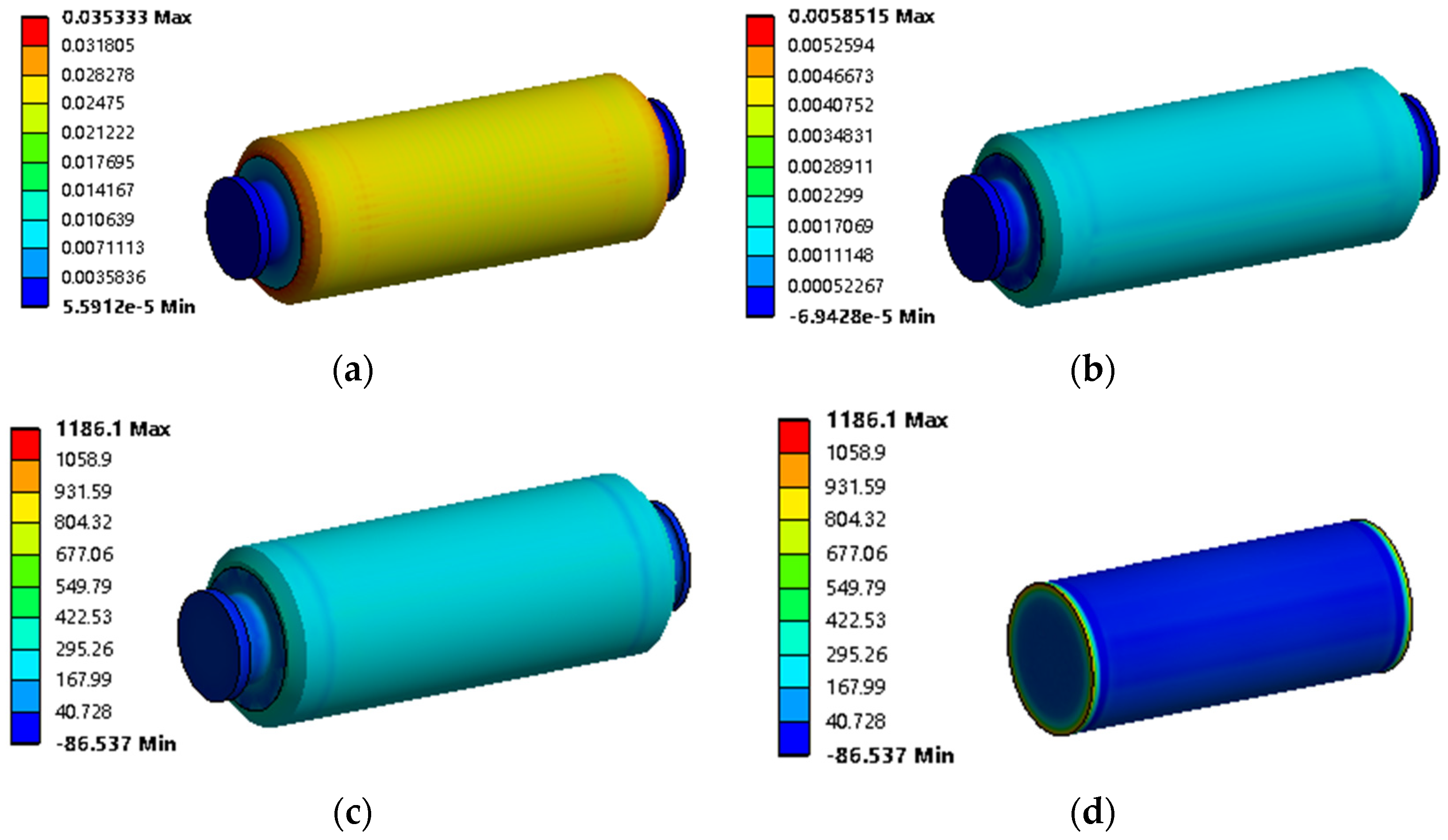
The speed selected for the simulation is set according to the actual working needs. The rated speed under a normal working condition is 88,000 rpm, and the working temperature is 22 °C. The interference of the rotor system is taken as 60 μm. Stress, deformation, and elastic strain are added as the output results to analyze the strength condition of the rotor.
3.3.1. Result Analysis
As shown in
Figure 6a–c, the maximum deformation is 35.33 μm; the maximum elastic strain is 0.00585; and the maximum principal stress is 1186.1 MPa in the interference fit region of the rotor system. As shown in
Figure 6d, the maximum stress region which exceeds the permissible stress and where failure occurs is located at both ends of the magnet.
3.3.2. Radial and Axial Stress Distribution
In order to accurately locate the specific location of the stress failure, the radial path stress change in the sheath magnet and the axial path stress change in the mating surface are added according to the above results of the output stress figure. As shown in
Figure 7a,b, 200 nodes are sampled on the radial and axial paths, respectively.
Observing the location of the specific failure in the interference fit as shown in
Figure 8a,b, the radial and axial stresses are approximately symmetrical along their midpoints according to the results of the sampling nodes. There is an obvious stress mutation at the vertices where the sheath, magnet, and end covers are in contact. Comprehensive analysis shows that the end cover, magnet, and sheath squeeze each other in the interference fit. Great strain and deformation occur at both ends of the magnet cylinder, which is the contact edge effect of the interference fit that creates a stress concentration at the edge [
27].
3.4. Measures to Reduce Maximum Stress
3.4.1. Chamfers Position of Interference Fit Structure
According to the structure of interference fit in the rotor system, two methods of cutting 45° chamfers, meaning that the top of both sides of the magnet and the top of the two end covers are added, respectively, are adopted. Comparing the two different structures under the condition of keeping the speed, temperature, and interference consistent above, to change the position of the chamfers, rebuild the model, and simulate, the result is the chart of stress distribution along the radial section, as shown in
Figure 9. Setting the chamfers to 0.5 mm as an example, chamfers are added on the magnet and the end covers, respectively, to compare the parameter changes in them. The maximum principal stress on the sheath is 337.55 MPa and 308.42 MPa, respectively, which is significantly lower than the structure without chamfers, and the maximum stress is also within the range of allowable stress.
Based on the radial and axial stress distribution of the original structure, the stress distribution data of magnet chamfers and the end cover chamfer structure are added. As shown in
Figure 10, a comparative diagram of stress distribution is drawn.
The simulation parameters of the three structures are compared and analyzed, as shown in
Table 2. Under the normal working condition, there is little difference in the total deformation and elastic strain among the three structures. However, there is a great difference in the maximum principal stress between the original structure and the two chamfered structures. The maximum principal stress of the magnet chamfers structure and the end cover chamfers structure is on the sheath, and the maximum stress of the end cover chamfers structure is smaller than the former.
Considering the processing factors, it is difficult to process the magnet because of its brittleness and easy-to-produce cracks at the top. Therefore, to choose the chamfered structure of the end cover, on the one hand, the material of the end cover is structural steel, which is convenient for processing; on the other hand, the maximum principal stress of the chamfered structure of the end cover is smaller.
3.4.2. Chamfers Size of the Interference Fit Structure
In conclusion, choosing to add chamfers at the end cover can reduce the maximum principle stress and prevent the problem of strength failure in the structure of the interference fit. According to this design, we make the simulations of the end cover chamfers range from approximately 0.3 to 1.0 mm in order to compare the effect of the size of the chamfers on the stress of the interference fit structure. The exploratory results are shown in
Figure 11.
By increasing the end cover chamfers, the stress in the interference fit region shows a decreasing trend. When choosing the chamfer size, we should consider the size of the stress and the material and processing of the end cover so as to ensure that the maximum principal stress of the interference fit is small, and that it is easy to process and reduce the material loss.
4. Results and Discussion
After changing the geometric structures, that is, adding a chamfered structure to the end covers, the local high stress of the interference fit can be greatly reduced. On this basis, we continue to explore the factors affecting the strength of the rotor. According to the degree of change in the strain, deformation, and stress, the change in stress is more significant than others, so the following is mainly through the change in stress to show the influence of various factors on the strength of the rotor.
4.1. Amount of Interference
The rated speed of the centrifugal compressor used in the experiment is 88,000 rpm, the highest speed is 96,000 rpm, and the maximum speed is increased by 16.7%, that is, 112,000 rpm.
For the rigor of the conclusion, the speed 60,000 rpm under the rated speed is compared with the former. The structure of end covers used in the simulation is C0.5 in order to analyze the stress and strain of the rotor system at different speeds.
Within the range of effective interference, the rated and maximum rotational speed are combined with different interference, and the influence of interference on the rotor strength is analyzed. As shown in
Figure 12, when the interference amount is between 10 and 40 μm, the maximum principal stress at a low speed of 60,000 rpm shows a steady upward trend. However, when the speed is >88,000 rpm, the influence of the interference amount on the stress is not obvious. When the interference amount is greater than 40 μm, the maximum principal stress increases linearly with the increase in the interference amount. The specific simulation data points are shown in
Table 3.
4.2. Rotational Speeds
When the chamfer of the end covers is C0.5 and the interference amount is 60 μm, the effect of rotor speeds on the stress of the interference fit structure is analyzed. The simulation data results are shown in
Table 4. It is known that the relationship between the centripetal force and rotational speed is quadratic. In addition, the stress generated by the sheath and the magnet is the compression force among the layers, and the sum value of the compression force of each layer is equal to the centripetal force and the direction is opposite. So, the maximum principal stress is also a quadratic correlation with speeds, as shown in
Figure 13. Therefore, the speeds are also one of the factors for the comprehensive consideration of the rotor interference fit strength.
4.3. Temperature
When exploring the factors of rotor strength, temperature is also one of the factors that cannot be ignored. In the simulation, the temperature and stress field changes in the rotor system are mainly considered. The rotor system is regarded as an isothermal body, and the temperature load is applied to it to analyze the stress changes in the interference fit structure at different temperatures. The temperature range selected in the simulation corresponds to the actual working environment. The actual minimum operating temperature is 20 °C. On this basis, the temperature is increased to find the highest range that the system can withstand. The unit for the temperature values mentioned is Celsius.
When exploring the correlativity between temperature and stress, the coefficient of thermal expansion is an important parameter to be considered. The coefficient of the thermal expansion of the magnet, sheath, and end covers do not change obviously when the temperature ranges from 0 to 400 °C. Their coefficients of thermal expansion are approximately linear with temperature. Therefore, it is determined that the average coefficient of the thermal expansion of the magnet is 9 × 10
−6/°C, and that of the sheath and end covers is 1.7 × 10
−5/°C. The metal strength decreases when the temperature is increased. At about 250 °C, the strength of the metal increases slightly. However, the reduction in the metal strength is not obvious below 200 °C [
28]. In this case, the change in the strength can be ignored.
As shown in
Figure 14, the sheath is a thin-walled part where stress is affected weakly by the change in temperature. However, with the increase in temperature, the stress of the magnet and end covers increases gradually, and strength failure does not occur until up to 183.11 °C.
According to
Figure 15, it can be determined where the failure occurs. The failure position of the magnet is on both end faces, while both end covers fail at the top of the small diameter sides. From the simulation results, it can be obtained that the operating temperature of the rotor system should not be too high, and it should be kept below 183.11 °C to avoid a high temperature, leading to the strength failure of the magnets and end covers.
Compared with ordinary motors, high-speed motors have a high speed and large vibration, so the heating problem is more serious when working, which leads to the change in interference fit contact stress. In order to further understand the influence of temperature on the interference fit structure, from the point of view of strength failure, simulation is used to analyze the temperature, under which a failure problem will occur within the range of effective interference.
According to the above results, when the temperature gradient rises, the contact stress of the interference fit structure also increases. Therefore, the failure temperature point of the interference fit structure can be determined at a high working temperature. With the standard interference quantity of 60 μm and failure temperature of 183.11 °C as the reference, the temperature of the interference fit structure strength failure within the range of the effective interference quantity is further explored. A summary of the final results is shown in
Figure 16. When the interference volume ranges from 20 to 70 μm, the temperature reaching the failure condition decreases step by step and reaches the inflection point, at which time the temperature is 182.3 °C. From 80 to 90 μm, the failure temperature gradually increases, and it rises to 190 °C at 90 μm. Excluding other possible influencing factors, the results are still consistent after multiple simulation verification. The possible reason is that the thermal expansion coefficient of the sheath is higher than that of the magnet, the thickness of the sheath increases, the radial stress of the structure decreases, but the interference quantity also increases, resulting in an increase in the contact stress. The stress value of the overall structure shows an upward trend before the interference value increases to 70 μm. With the accompanying effect of temperature, the failure temperature gradually decreases. But after that, the stress value of the structure gradually decreases, resulting in the rate of increase in stress slowing down as the temperature rises. This study can provide a certain reference significance for the allowable working temperature range of the rotor.
4.4. Thicknesses of the Sheath Wall
After the chamfers are added to the end cap, the simulation results show that the maximum principal stress area of the interference fit structure changes from the end face of the magnet to the inner wall of the edge of the magnet sheath. Therefore, the influence of the sheath thickness on the interference fit structure can be studied. Based on this conclusion, the interference amount is kept at 60 μm at the rated speed of 88,000 rpm. Under the premise of no sheath damage failure, different wall thicknesses of the sheath are selected for the simulation results, and these are shown in
Figure 17 below. The stress on the sheath is in the minimum range when the sheath wall thicknesses are between 4.5 and 4.75 mm.
As shown in
Figure 18, when the sheath wall thickness is too small, the deformation resistance of the sheath is poor due to the effect of the interference fit, which causes high stress. Nevertheless, as the sheath wall thickness increases, the magnet plasticity is low and not easily deformed, so the total deformation of the sheath increases. While the sheath thicknesses are between 3 and 4.5 mm, the strain has a flat region and gradually increases thereafter. Until the sheath wall thicknesses are higher than 4.5 mm, the stress and strain generated by the sheath gradually increase. This improves the pre-stress of the sheath on the magnet. In the interference fit of the rotor, the priority of magnet protection is higher than that of sheath. However, too much thickness can lead to assembly difficulties and heat dissipation problems. Therefore, the thickness of the sheath should be determined according to the actual situation to achieve the best effect.
5. Conclusions
In this paper, the main influencing factors of the interference fit structure of a high-speed permanent magnet motor are analyzed, and the problem of the thermal failure of the rotor system is systematically studied. The results and research significance are as follows:
- (1)
A design method to reduce the edge stress concentration of the interference fit structure is proposed. The problem of stress concentration is improved by adding chamfer to the end covers of the interference fit structure. Through adding chamfers to the end covers, the maximum stress of the structure is reduced from 1186.1 MPa to 308.42 MPa, which effectively reduces the stress of the structure. This could provide a basis for the design of the structure.
- (2)
The reliability of the interference fit structure decreases as the amount of interference increases in the range of effective interference. When the rotational speed reaches 136,000 rpm, the structure will suffer loose speed and fail. In the actual working situation, when the speed of the high-speed permanent magnet motor approaches the critical speed, it is necessary to pay attention to the operation of the motor, and the speed cannot exceed the limit to avoid rotor structural failure and safety accidents.
The wall thickness of the sheath should be appropriate to achieve sufficient preload while the interference fit structure meets the strength requirements and plays a role in protecting the magnet. To ensure the reliability of the rotor system strength, the operation of a high-speed permanent magnet motor can be stable.
- (3)
The rise in temperature in the rotor system has a small effect on the stress of the sheath, but the stress on the magnet and end covers increases with the rise in temperature. According to the simulation results, it can be seen that when the temperature reaches 183.11 °C at 60 μm, the strength of the structure fails. Considering the safety, the failure temperature of the interference fit structure at different interference values is analyzed. The results show that the operating temperature of the rotor system should not exceed 180 °C as far as possible in practice. In necessary cases, heat dissipation measures for high-speed permanent magnet motors, such as air-cooling of the rotor and water-cooling of the external shell to indirectly reduce the operating temperature of the rotor, so as to ensure the reliability and safety of the system during operation.
It is necessary to acknowledge the limitations of this study. In the simulation, some minor influencing factors are normalized. In the actual working environment, the factors affecting the operation of a high-speed permanent magnet motor are not limited to the discussion in this paper. The findings in this study can provide a reference for designing the rotor structure of a high-speed permanent magnet motor, and a future study with a larger cohort size is needed to test the specific parameter requirements in practice.


