Article

Winding Loss Suppression in Inverter-Fed Traction Motors via Hybrid Coil Materials and Configurations

1
Department of Electromechanical, Systems, and Metal Engineering, Ghent University, 9000 Ghent, Belgium
2
FlandersMake@UGent, Core Lab MIRO, 3001 Leuven, Belgium
3
Department of Electrical Engineering, Faculty of Engineering, Menoufia University, Menoufia 32511, Egypt
4
Department of Electrical Engineering, Kafrelshiekh University, Kafrelshiekh 33511, Egypt
*
Author to whom correspondence should be addressed.
Appl. Sci. 2023, 13(20), 11429; https://doi.org/10.3390/app132011429
Submission received: 13 September 2023 / Revised: 12 October 2023 / Accepted: 17 October 2023 / Published: 18 October 2023

Abstract

:
In a typical inverter-fed AC drive system, the stator windings carry a current with a large harmonics content, resulting in an increased AC loss. In this paper, the additional copper losses caused by non-sinusoidal currents are investigated for different magnet wire topologies, including the flat conductor, stranded, and litz wires. Also, a two-slot simplified model is introduced for accurate prediction of the AC losses at high frequency. It is found that one of the major issues of the conventional copper coil is that the losses are not uniformly distributed across the slot, and over 70% of the losses are concentrated near the slot opening. Moreover, using the transient finite element method, different winding topologies and arrangements are simulated at the stranded level to evaluate the losses and current density for each strand under highly distorted currents. Furthermore, different coil samples are prototyped for the same slot geometries to compare their performance under the same pulse-width modulation (PWM) waveforms for a wide range of frequencies. Finally, new hybrid coil topologies are proposed, which employ different magnet wires or materials within the same slot. The results demonstrate that utilizing a mixed wire configuration can effectively mitigate the adverse effects of eddy current losses. This approach can yield up to 16–41% lower losses while also achieving a weight savings of 36–70%.

1. Introduction

The automotive industry has witnessed remarkable growth, marked by a recent surge in the development of downsized electrical machines with the aim of improving the energy efficiency of electric vehicles (EVs) [1,2,3]. Nonetheless, one of the foremost challenges confronting this pursuit is the inevitable tradeoff that arises when reducing the physical dimensions of these machines, leading to a reduction in both output torque and power. To address this issue and sustain a commendable power density, a compelling approach entails raising the operational speed of the machine. This strategy, while promising, comes with the drawback of a higher operating frequency, resulting in a concomitant increase in AC losses within the machine windings [4].
In response to this sizing dilemma, permanent magnet (PM) electrical machines have emerged as a promising solution. These machines do not possess rotor windings and are well suited for high-speed operation, exhibiting exceptional efficiency and reliability across a broad speed range. Moreover, they offer a cost-effective solution for EVs while maintaining high power density [5,6]. Additionally, the PM-assisted synchronous reluctance machine (PMa-SynRM) has been introduced for similar applications, providing the advantage of fixed power operation and improved performance in high-speed scenarios [7,8].
The AC losses of machine windings experience a significant increase due to the skin and proximity effects at high-frequency operation [9,10,11,12]. Various methods have been documented in the literature to assess AC losses within these high-frequency machines, as listed in Table 1 [11,12,13,14,15,16,17,18,19]. In a study described in [20], AC losses were computed for a PMa-SynRM employing stranded wire conductors. In [21], a group of researchers conducted a detailed analytical examination of the eddy current losses occurring in the stator windings of an interior permanent magnet (PM) machine. Their study specifically focused on a multi-strand coil configuration. Another approach outlined in [22] proposed the use of rectangular conductors to reduce AC resistance in an EV traction motor. Additionally, in [23,24], investigations were conducted using the finite element method (FEM) to calculate high-frequency copper losses in flat hairpin windings. It is worth noting that all of the aforementioned methods assumed a pure sinusoidal current excitation when using the FEM to analyze the machine windings. However, in practical PMa-SynRMs, the machine is powered by an inverter with pulse-width modulated (PWM) current, leading to the introduction of additional AC losses due to generated harmonics.
This paper presents a comprehensive investigation into winding losses under non-sinusoidal current excitation, with a specific focus on various winding topologies, all analyzed using finite element method (FEM) simulations at the strand level for inverter-fed motors. The studied topologies encompass rectangular flat conductors and stranded wires. Furthermore, the study involves the prototyping of various coil samples. The primary objective is to minimize AC losses, and through rigorous analysis, we identify the winding configuration that exhibits the best electromagnetic performance across different frequency domains. In conclusion, this research explores innovative hybrid coil configurations to effectively mitigate the adverse effects of high-frequency AC losses. By incorporating different wire materials within the same slot, this approach demonstrates significant reductions in losses and offers substantial weight savings, making it a promising advancement for electric vehicle and motor drive technologies.
This paper investigates AC copper losses in inverter-fed electrical machines, focusing on various winding topologies and magnet wire materials. Key findings and innovations include:
  • Evaluating different wire topologies: This study explores flat conductor, stranded, and litz wire topologies to assess their impact on AC losses in electrical machine windings.
  • Optimal material distribution: It reveals that in conventional copper coils, over 70% of losses are concentrated near the slot opening, creating an imbalance in loss distribution.
  • Hybrid coil solutions: New hybrid coils are proposed, featuring combinations of materials such as copper, aluminum, and 3D-printed alloys to achieve more balanced loss distribution and weight reduction.
  • Loss reduction: The hybrid coils significantly reduce losses, with up to 41% lower losses compared to traditional copper coils, while also achieving substantial weight savings.
  • Strand transposition: This study introduces strand transposition techniques, further reducing losses and enhancing current density.
  • Practical core loss measurement: A practical approach for core loss measurement and iron loss separation is introduced, enhancing the accuracy of loss assessments.
  • Frequency impact: The impact of operating frequency on losses is examined, providing insights into the performance of different coil designs under various conditions.
  • Novel hybrid coil topologies: This paper presents innovative hybrid coil designs that incorporate multiple magnet wire materials within the same slot, offering improved performance and efficiency.
In summary, the novelty of this paper lies in its comprehensive exploration of winding topologies, innovative hybrid coil solutions, practical measurement techniques, and the efficient reduction of AC losses and weight in electrical machine windings. These findings have significant implications for improving the performance and efficiency of inverter-fed AC drive systems.

2. Case Study of Inverter-Fed Electrical Motor

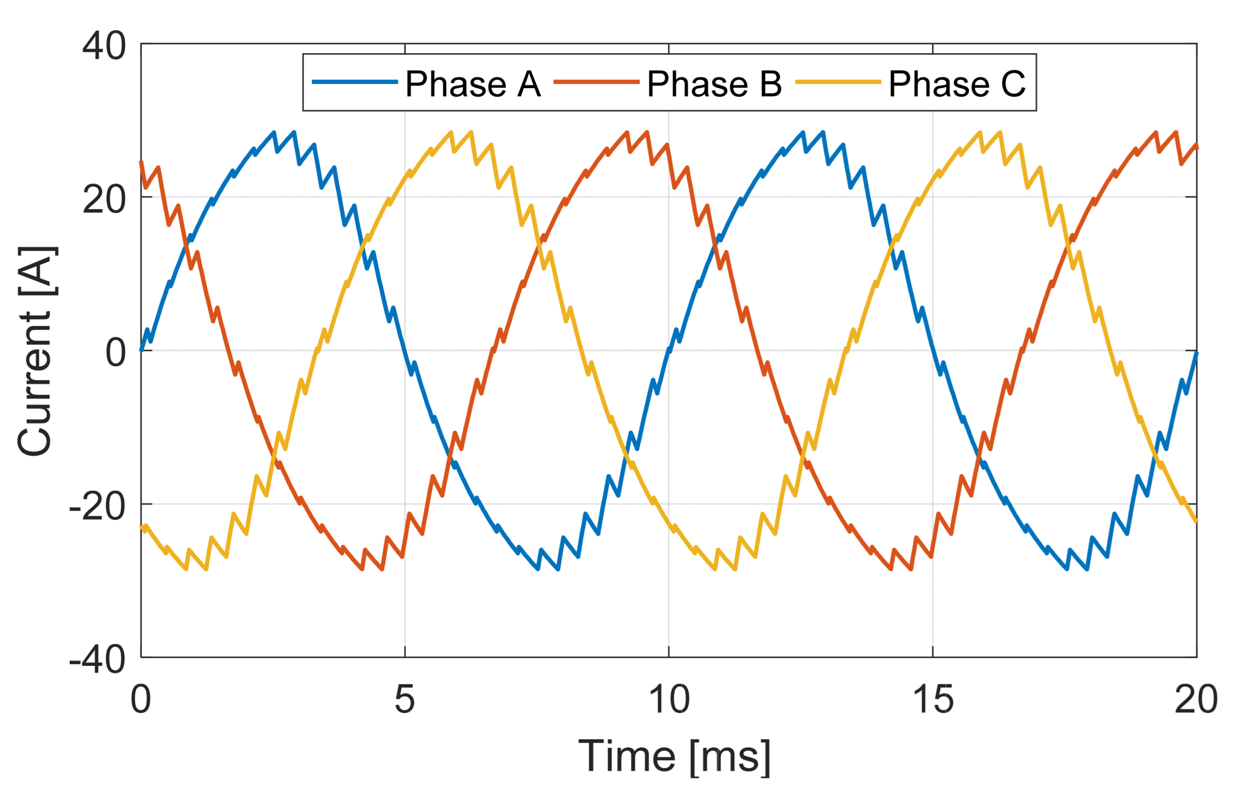
The vast majority of modern electrical machines use inverters for variable frequency drive and speed control. A common example of an inverter-fed machine is a surface-mounted PM motor. Figure 1 shows the machine configuration along with the winding layout. The windings have a concentrated layout without any overlap. As a result, the machine has nearly the same output power with a much lower stack length compared to the machine with distributed windings. In the rotor design, a 22-pole PM array is used. The machine’s dimensional specifications and electromagnetic parameters are listed in Table 2. The operation of this machine involves excitation through a three-phase inverter, leading to the generation of non-sinusoidal currents in the stator windings. In Figure 2, we present the measured three-phase current waveforms at base speed. The primary emphasis of this paper revolves around the additional winding losses induced by these highly distorted current waveforms.

3. Winding Simulation at Strands Level

3.1. Simplified Flat Winding Model

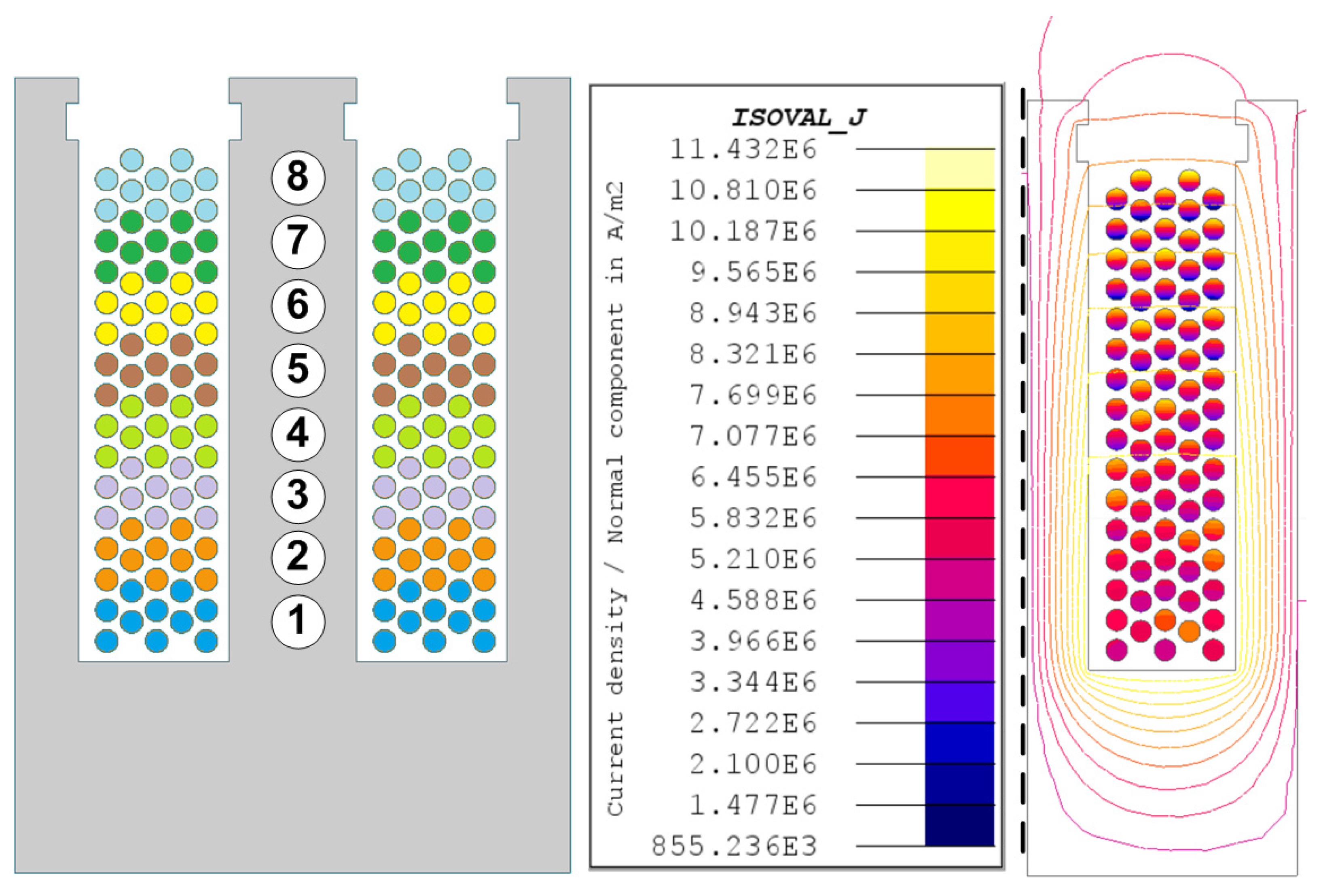
In order to evaluate the electromagnetic performance of the windings, the winding domain must be divided into smaller regions in each slot during finite element analysis (FEA). Doing that for a complete machine is time-consuming and almost not possible. That is why the benchmarked machine is simplified to a motorette of two slots with an E-shape core. Using a two-slot model, a coil is simulated at the stranded level, with each conductor represented individually, as shown in Figure 3.
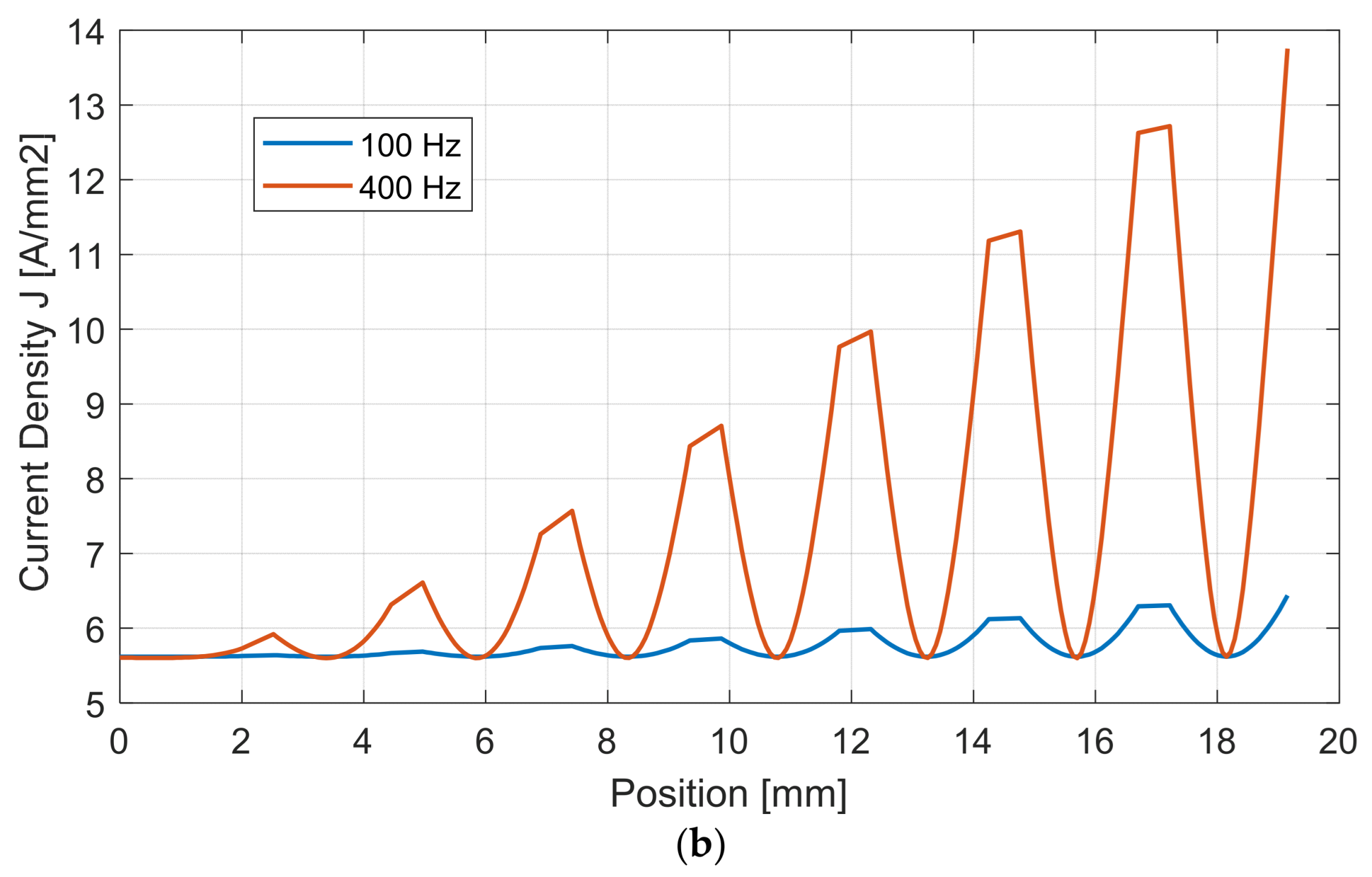
Furthermore, the current density is evaluated in the optimal 8-turn coil under sinusoidal wave current at two different frequencies (100 Hz and 400 Hz), as shown in Figure 3b. It is evident from the data that the current density exhibits a gradual rise along the slot height, with the highest point of current density positioned in the upper conductor. This concentration can be attributed to the elevated slot leakage flux in the proximity of the slot opening. Moreover, as the frequency escalates from 100 Hz to 400 Hz, the maximum current density experiences a substantial increase of more than 130%.
We explore the previously mentioned two-slot model under two distinct current waveforms, as depicted in Figure 4. The first waveform is a pure sinusoidal one devoid of any harmonic content. The second waveform is a pulse-width modulation (PWM) current characterized by a substantial presence of harmonics. To ensure a fair comparison, it is important to note that both the sinusoidal and PWM currents have identical root mean square (RMS) values. Also, the PWM waveform has the same base frequency of 100 Hz and a switching frequency of 6600 Hz. The power losses in each turn are calculated, as shown in Figure 5. Notably, the PWM current has a high impact on the losses, especially in the upper conductors. It is also clear that over 75% of the total losses are generated within the top three conductors near the slot opening.
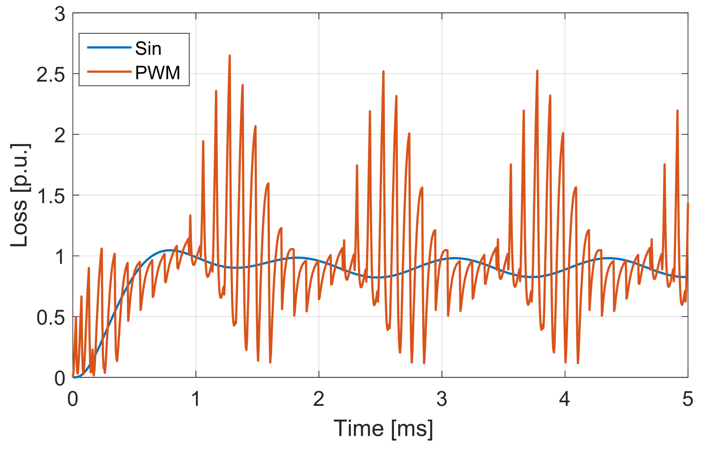
A transient FE analysis was conducted using the aforementioned current waveforms. We calculated and compared the instantaneous copper losses for both waveforms at 100 Hz, as illustrated in Figure 6. Notably, the presence of harmonic content results in an approximate 30% increase in losses at this frequency level. Additionally, the transient maximum current density is plotted for both waveforms, as shown in Figure 7. Under PWM, the current density is spiking to very high levels with at least a 50% increase compared to the pure sinusoidal current.

3.2. Stranded Wires Configuration

In pursuit of minimizing AC losses, an alternative winding configuration employing stranded conductors within the same slot geometry was thoroughly investigated. Typically, such windings are positioned randomly within the stator slot, making it challenging to determine the exact position of each strand. To address this practical concern, the strands were transposed to different locations within the slot for a more realistic simulation. A 10-strand coil, maintaining the same number of turns as the flat solid conductor case, is simulated, as depicted in Figure 8.
Furthermore, a comprehensive comparison between both configurations, focusing on the maximum current density, is presented in Table 3 at a frequency of 100 Hz. At this frequency level, the flat solid coil exhibits a more favorable current density distribution solely under a pure sinusoidal current waveform. However, when high-frequency harmonics are introduced, the stranded coil demonstrates a relatively superior current density profile.
The effect of the PWM current on copper losses is shown in Figure 9 at different frequency levels. As can be seen, the losses increase remarkably as the frequency increases. For instance, at 1 kHz, the losses are more than twice their value under sinusoidal excitation, while at 2 kHz, the losses are more than three times their value.
The iron losses are also investigated for the E-shape core under different current waveforms. The core loss and its components are shown in Figure 10, including hysteresis, eddy, and excess losses. As can be noticed, the eddy current losses are the most affected component, especially at high frequency levels. As a result, the core losses increase significantly under PWM current.

3.3. Effect of Strand Transposition

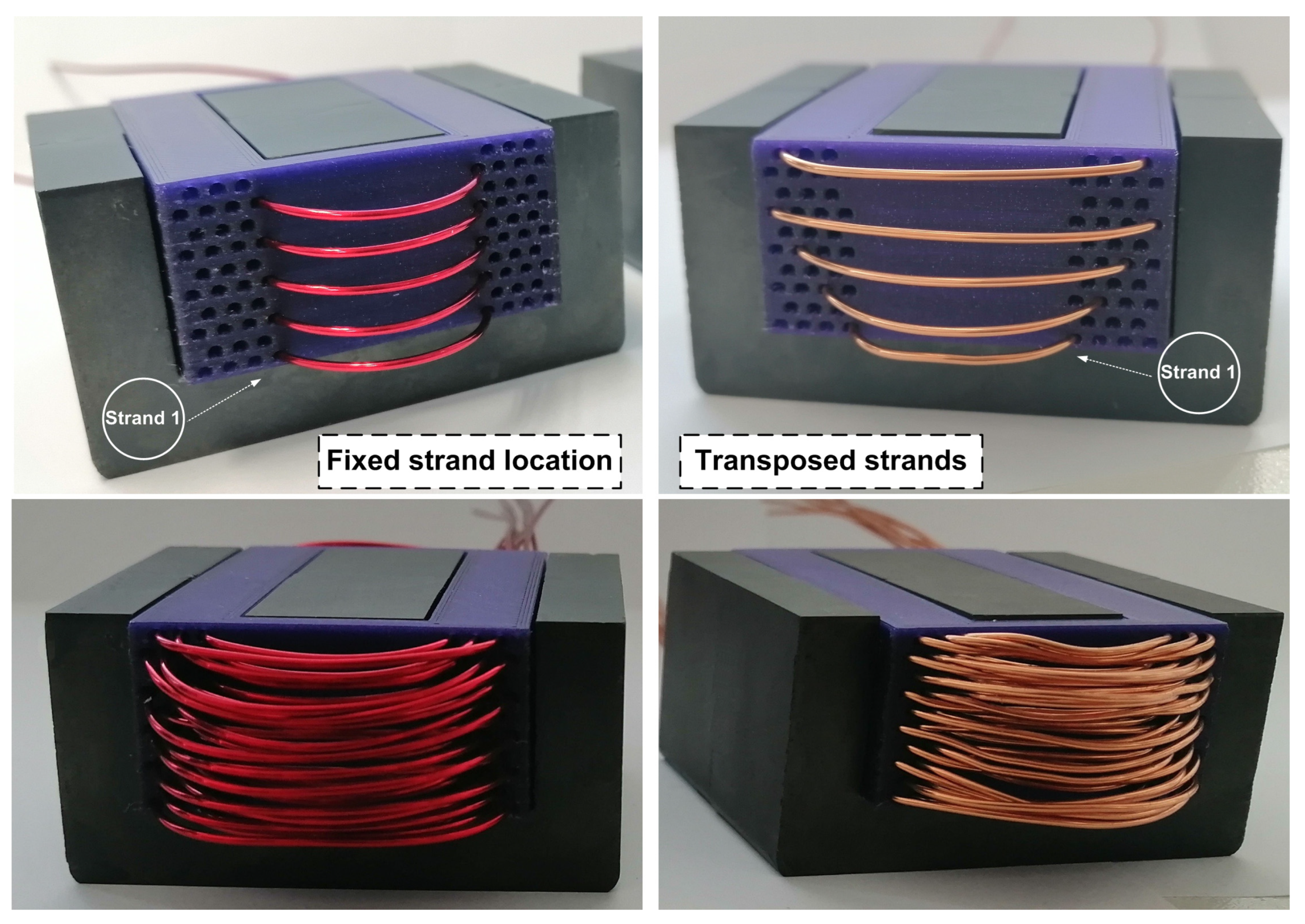
In stranded windings, the location of each conductor is hard to control. That is why the conductors are placed randomly inside the stator slot, resulting—most of the time—in higher losses. In order to investigate the effect of strand transposition on AC losses of windings, two samples are prototyped using traditional stranded round wire. In both samples, a coil support is used to have a defined location for each strand, as shown in Figure 11. As shown in this figure, the first sample has five turns and seven strands per turn with a fixed strand location. In the second sample, the same number of turns and strands is used. The only difference is that the strands are transposed to different locations using a special pattern. In this pattern, each strand is moved one location after the transition to the next turn.
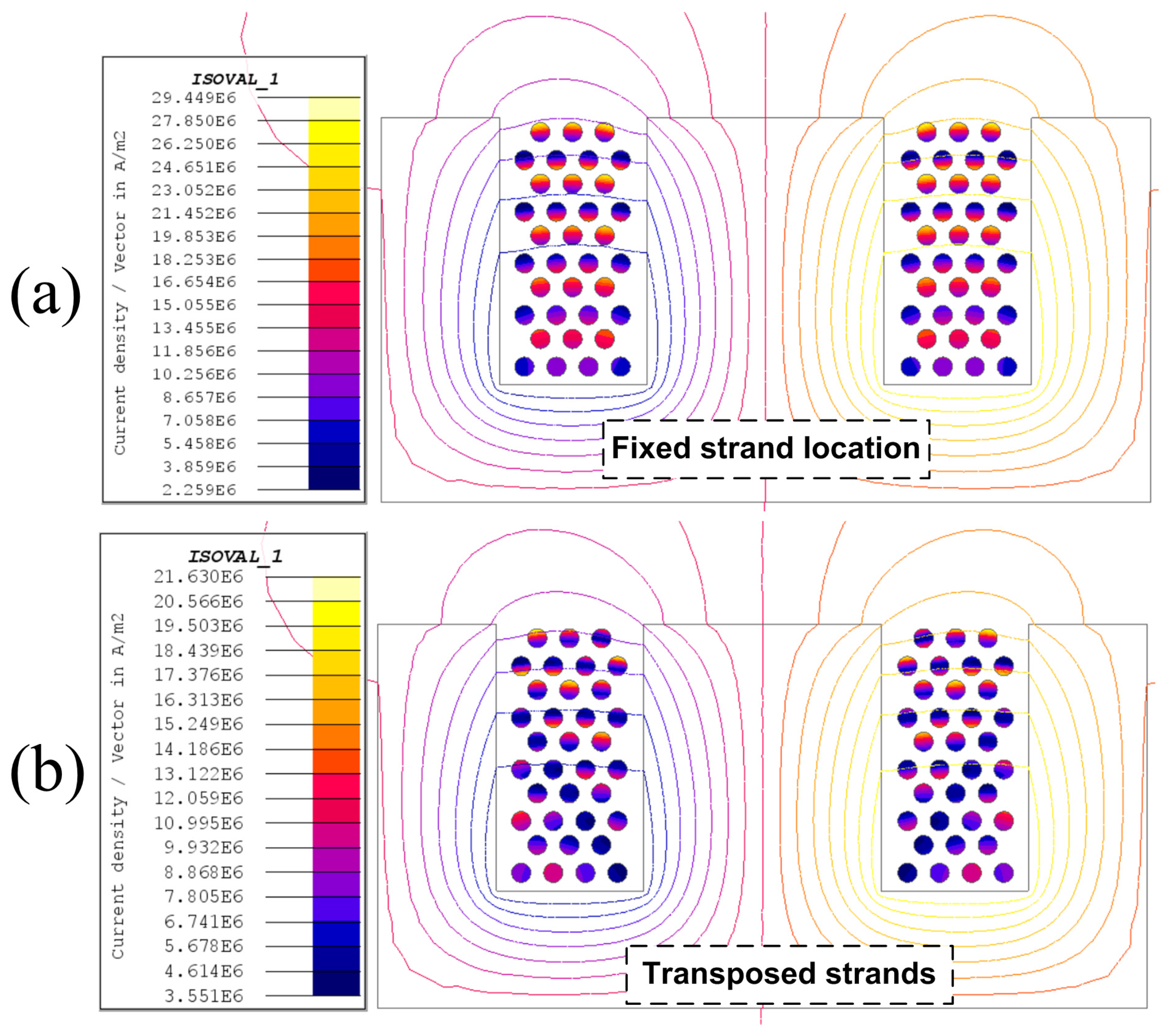
Both of the aforementioned arrangements are simulated using the FEM under the same current level at a frequency of 1 kHz, as shown in Figure 12. It is clear that the maximum current density in the case of transposed locations is 26% lower than its value in the case of fixed strand locations. Therefore, the strand transposition will limit the AC losses, especially at a high frequency.
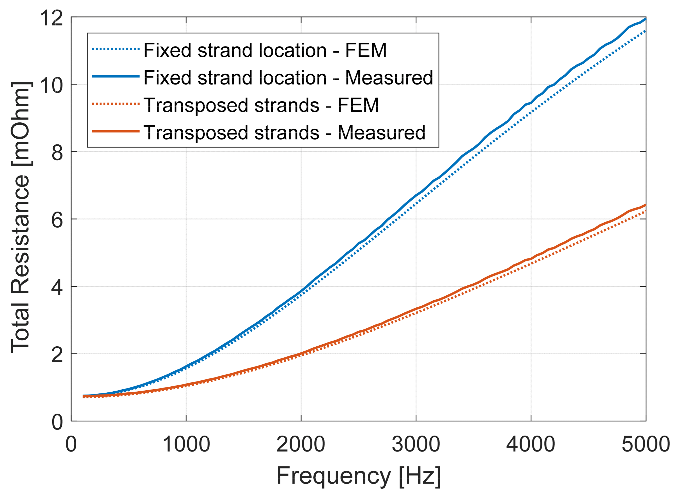
For additional verification, both samples are prototyped using the same wire gauge, as shown in Figure 13. These plastic supports are intended only for accurately studying the effect of controlled transposition and not for inserting in real machines because of the low fill factor and bad heat evacuation. The coil resistances are measured using an RLC meter. Also, the measured resistances are compared with the simulated values up to 5 kHz. A very good agreement is obtained between the simulation and measurements, as shown in Figure 14. It is also clear that the transposed strand coil can provide remarkably lower AC losses, especially at high frequencies. For instance, at 2 kHz, the coil resistance is nearly 50% lower in the case of the transposed stranded coil. With this being said, a flat litz wire is used as one of the test samples to compare its performance with the conventional stranded windings.

4. Experimentation and Loss Separation

4.1. Coils Preparation and Test Setup

In order to validate the effectiveness of each coil design, five coil samples are manufactured using different magnet wire topologies. For a fair comparison, all the samples have the same number of turns. Additionally, all the samples are connected in series so that the electromagnetic performance is compared under the same current. The five designs are explained as follows:
  • Coil I: Flat copper coil with a single solid strand [Figure 15].
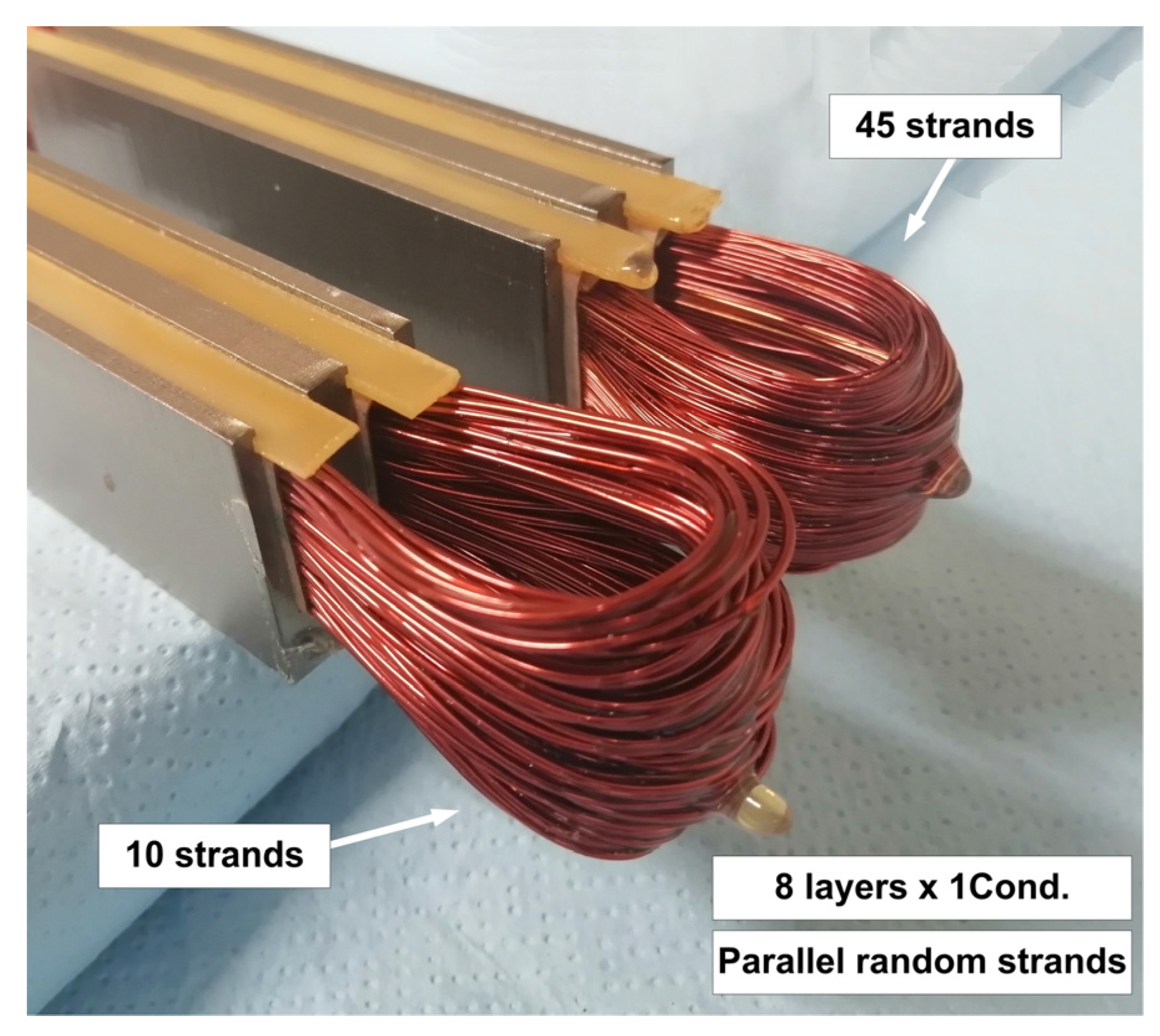
  • Coil II: Stranded coil with 10 parallel strands [Figure 16].
  • Coil III: Stranded coil with 45 parallel strands [Figure 16].
  • Coil IV: Flat litz coil with 45 strands [Figure 17a].
  • Coil IV: Flat litz coil with 45 strands (vertical) [Figure 17b].
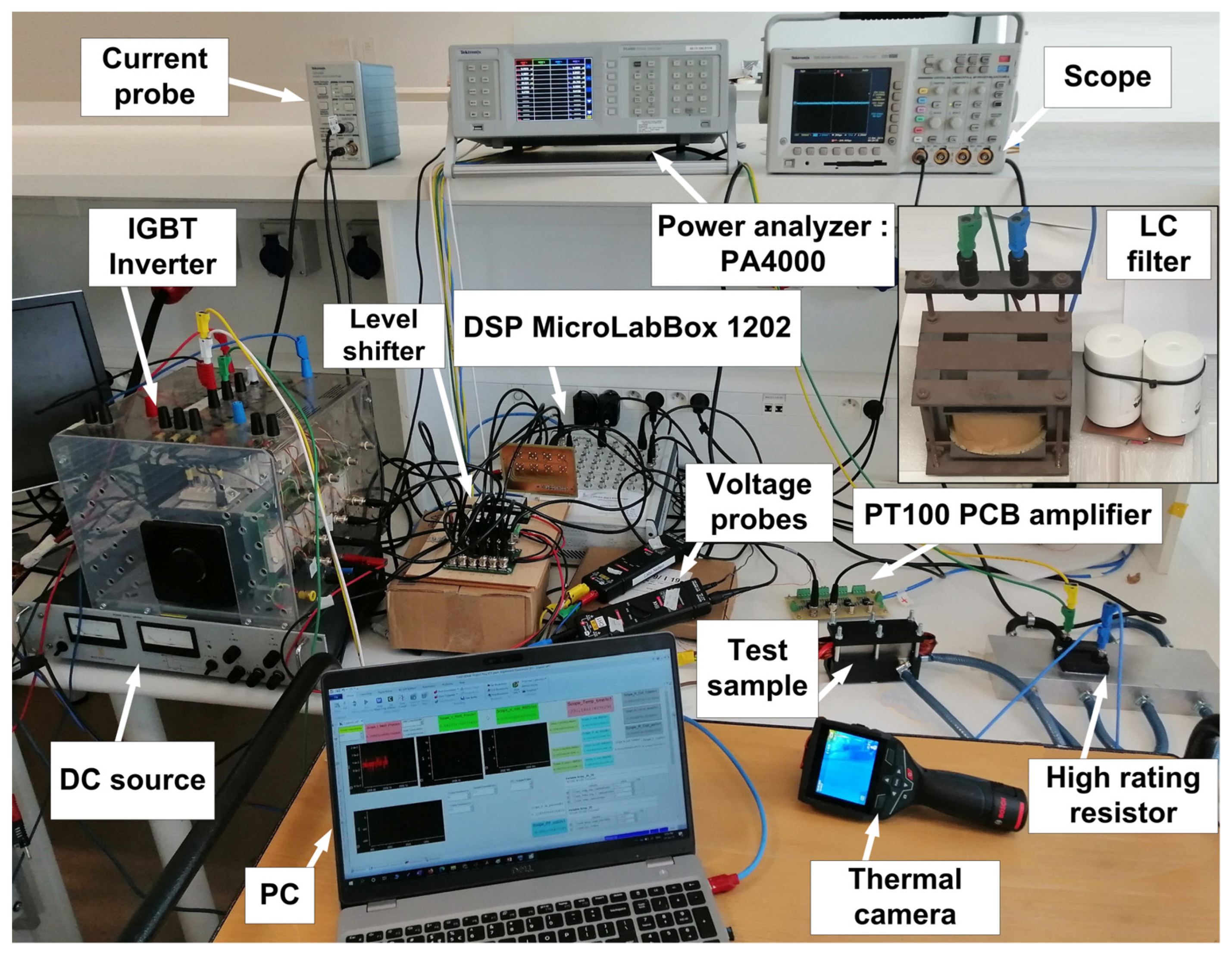
The winding losses are measured for different samples using the test setup in Figure 18. It consists mainly of a DC voltage source, an IGBT inverter, V-I sensors, and a data acquisition (DAQ) system. A dSpace MicroLabBox 1202 is used to control the PWM current waveform. Also, an LC filter is used to filter the high-order harmonics in the AC output of the inverter. Moreover, a thermal camera (GTC400) is used to monitor the temperature of the windings. There is also a multi-channel power analyzer (Tektronix PA4000) used to measure the power losses. A scope (Tektronix TDS3054) is used to monitor the waveforms. Finally, all test samples are connected in series with a water-cooled power resistor to limit any excessive current.

4.2. Winding Losses Results

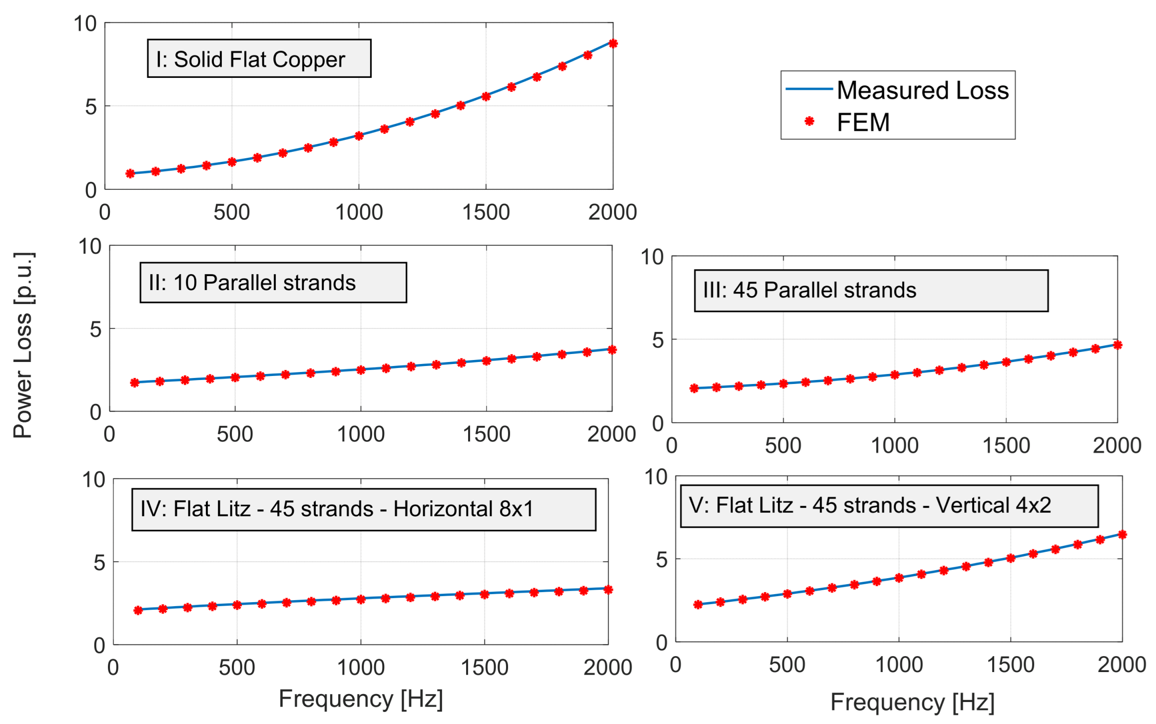
Under the same current level, the winding losses are then measured for each coil case at different frequency levels. The measured winding losses are compared with those obtained using the FEM, as shown in Figure 19. A very good agreement is obtained between all these approaches. Further, the measured winding losses of all five samples are compared in Figure 20. It is found that the flat copper coil (Coil I) has the lowest loss up to 400Hz. Above this frequency, the 10-strand winding (Coil II) has the lowest losses up to 1.5 kHz. At frequencies above 1.5 kHz, the flat litz wire with 45 horizontal strands (Coil IV) is the best choice.
Despite the flat coil (I) having low losses at low frequencies, the slope of its loss curve is the highest among all the samples. This means that AC losses in this coil increase much higher with frequency compared to the other stranded cases. On the counterpart, the flat litz coil (IV) has the lowest slope. As a result, it has remarkably lower AC losses, especially at high frequencies. Interestingly, this is not the case for Coil V, which has two vertical conductors per layer despite using the exact same wire. So, it can be concluded that using one conductor per layer is the optimal arrangement.
Also, by comparing Coil III and Coil IV, it is found that both coils have almost the same profile up to 800 Hz. At higher frequencies, the advantage of the twisted strands of the flat litz wire (Coil IV) results in a significant decrease in the AC losses compared to the coil with random parallel strands (Coil III).

5. Hybrid Coils for AC Loss Mitigation

At high frequency operation, the flat copper coil has an unbalanced distribution of losses through the turns. Over 70% of the total coil losses are found in the upper three strands. With this being said, hybrid coils are proposed to have a fair distribution of losses and limit them in the turns near the slot opening. This section introduces alternative materials and new design solutions to mitigate AC losses at a high-frequency operation.
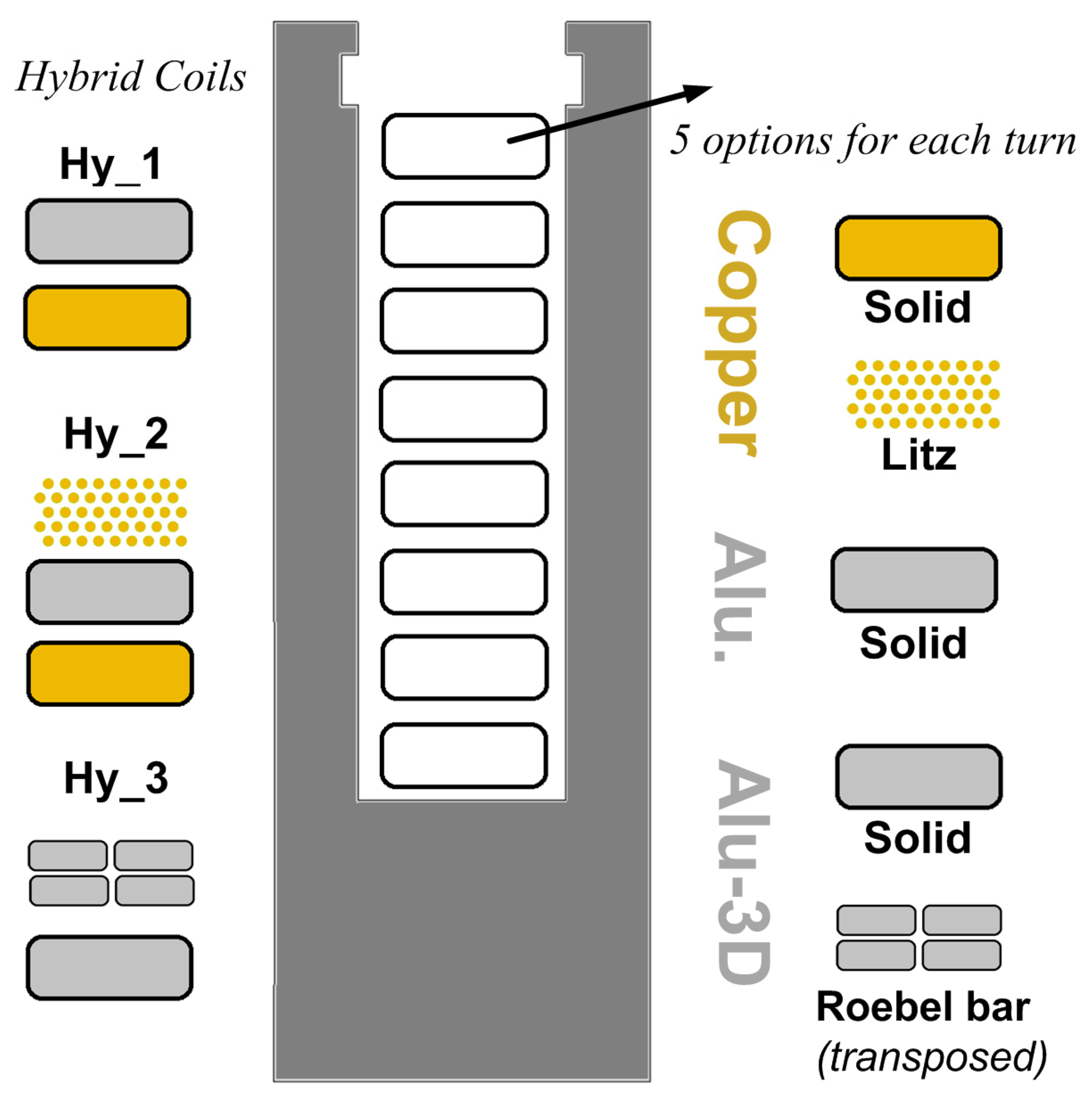
Different combinations of materials and magnet wires are used to form different hybrid-strand designs, as explained in Figure 21. Five magnet wire options are used to evaluate the losses at each strand, which are solid copper, flat litz, solid commercial aluminum (Alu), a 3D-printed aluminum powder made from Al–Si–Mg-based alloy (Alu3D), and finally, a Roebel bar with four transposed strands made from Alu3D. Typically, Alu3D powder is used as a feedstock for the additively manufactured part due to its higher printability compared to pure aluminum. The electrical conductivity of the Alu3D after thermal treatment is lower than that of commercial aluminum, with a value of ~20 M S/m. Yet, the mass density of both materials is almost the same.
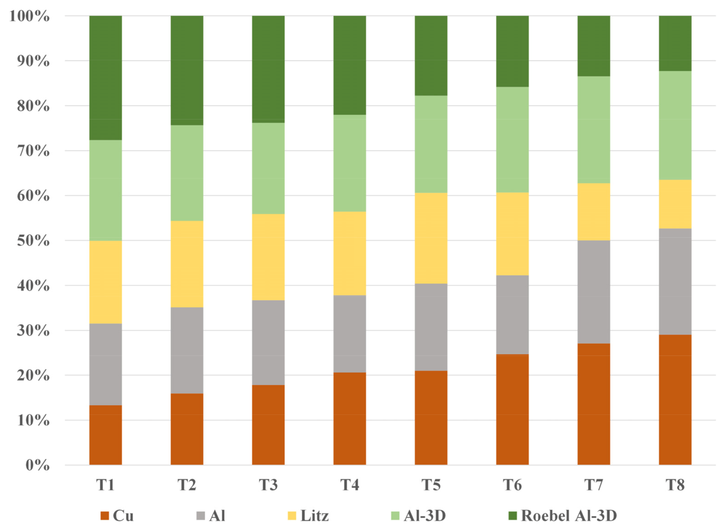
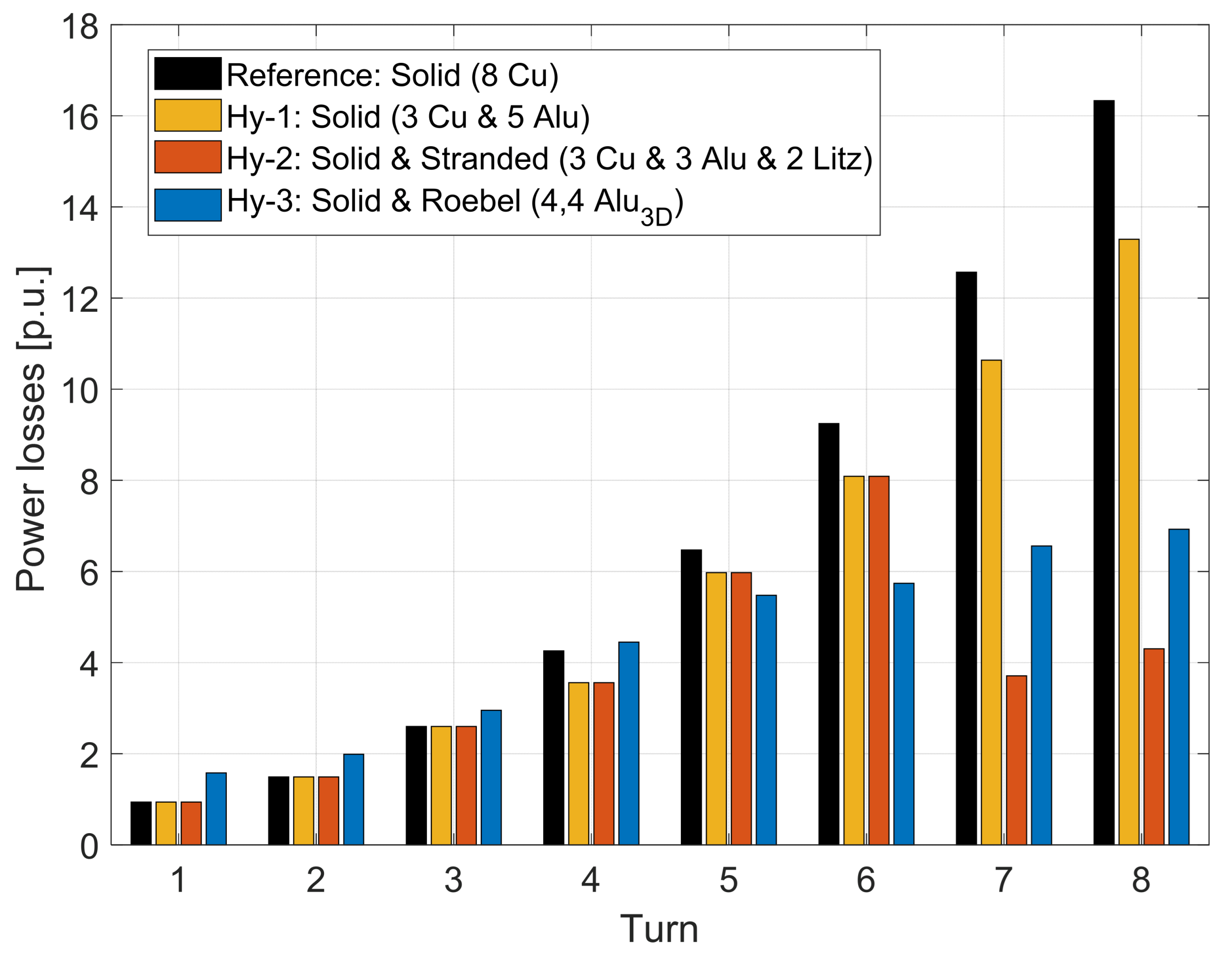
Using the aforementioned five wires, the core is simulated using homogenous turns, and the losses are calculated in each turn. In Figure 22, the losses in each turn are compared in percentage using these materials. As can be seen, using a certain material for all turn locations is not the optimal design. For instance, in turn 1, copper has the lowest losses among all materials. However, in turn 8, it has the highest loss percentage. On the counterpart, the Roebel bar has the highest losses when used in turn 1. However, it comes in second place when it is used for turn 8, having nearly the same losses as the litz wire, which has the lowest losses. Considering the aforementioned, each type of wire has an optimal location. To give another example, the losses in the turn at the bottom of the slot are higher for aluminum wire compared to copper wire, whereas near the slot opening, the situation is reversed. Having said that, three hybrid coils are proposed as follows.
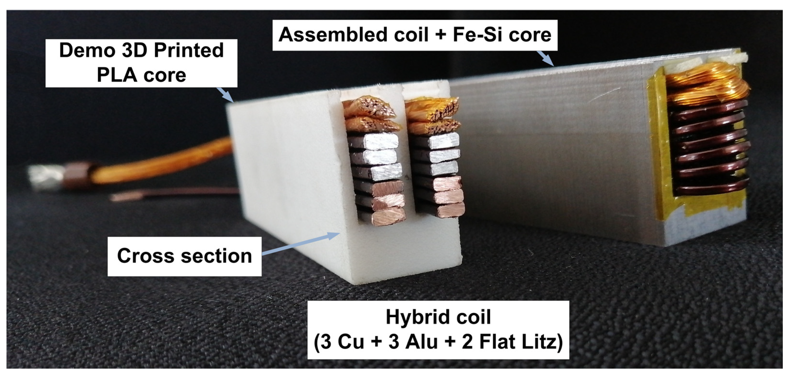
  • Hy-1: Flat solid (3 Cu + 5 Alu) [Figure 23].
  • Hy-2: Solid and stranded (3 Cu + 3 Alu + 2 Litz) [Figure 24].
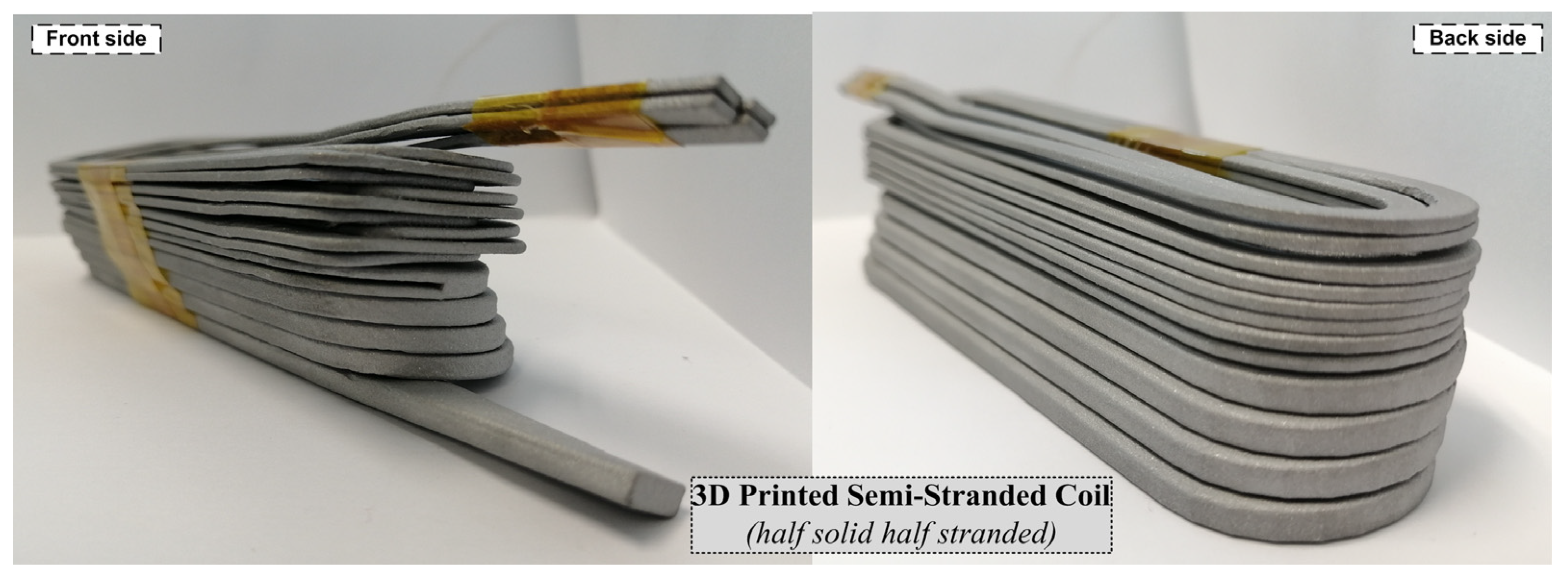
  • Hy-3: 3D-printed solid and Roebel (4, 4 Alu3D) [Figure 25].
In the first two coils (Hy-1 and Hy-2), copper is used for the first three turns because it has the lowest losses compared to all the other materials. However, this was not feasible for the printed coil because multi-material printing is not as advanced as single-material printing. In the third coil (Hy-3), the stranded section of the Roebel bar is transposed using the same pattern described earlier in Figure 12 and Figure 13. In order to achieve a higher fill factor inside the slot, the strand transposition is performed at the coil head. As a result, the current density in the semi-stranded coil is damped remarkably in the 3D semi-stranded coil compared to the conventional coil. Finally, the coil is 3D printed using Al–Si–Mg-based material produced via Laser Powder Bed Fusion (L-PBF), as shown in Figure 26. The electrical insulation is added in a post-process by dipping the coil in a varnish bath.
The losses in each turn are calculated for the three proposed hybrid coils, as shown in Figure 27. Compared to the reference copper coil, all coils have remarkably lower losses, especially in the top three strands. This is also verified by measuring the total losses at the same frequency level, as listed in Table 4. In Hy-1, the total coil losses are reduced by 16%, besides a 43% weight reduction. In Hy-2, the same design is used. However, the upper two turns are replaced with flat litz copper wire. The weight saving in this case is only 36% compared to the copper coil. However, this coil has the lowest losses with 41% lower losses. In Hy-3, the losses are reduced by 34%, and the coil has the lowest weight, with only 30% weight compared to the copper coil. In light of this weight–loss tradeoff, the proposed three-coil design is verified to be the best design solution compared to the previously mentioned traditional coils.
While 3D-printed materials may present themselves as a potentially superior alternative, there exist various challenges and considerations in their vicinity [25,26,27]:
  • Material properties: While aluminum alloys offer advantages, they may not have the same electrical conductivity as copper. Therefore, the design and application must consider the specific electrical properties required.
  • Post-processing: 3D-printed parts often require post-processing steps, such as heat treatment or surface finishing, to achieve the desired properties and surface quality.
  • Material costs: The cost of aluminum alloys can vary, and the cost-effectiveness of using Al–Si–Mg-based windings compared to copper or traditional aluminum windings depends on factors like material cost, production volume, and design complexity.
  • Certification and standards: In some industries, like aerospace, there may be stringent certification and standard requirements that need to be met when using alternative materials like Al–Si–Mg alloys.
  • High-volume production: Scaling up the 3D printing process to accommodate high-volume production often requires larger and more expensive equipment. This can lead to substantial upfront capital costs.

6. Conclusions

This paper investigates the AC copper losses for different winding topologies in inverter-fed electrical machines. Also, different winding topologies are simulated at the strand level using the FEM under PWM currents. This includes flat solid conductors and stranded windings. Moreover, the effect of strand transposition is simulated and verified experimentally using 3D-printed parts with controlled strand locations. The results are finally verified using different coil prototypes such as flat solid, parallel strands, and flat litz. Also, the impact of conductor placement inside the slot is investigated by comparing the same magnet wire under different conductors per layer. Even more, a more practical approach for core loss measurement is introduced for iron loss separation. A comparison is also made between all the implemented coils at different frequency levels, highlighting the best case. Finally, new hybrid coil topologies are suggested that incorporate various magnet wires within the same slot. The results demonstrate that employing a mixed wire arrangement can efficiently minimize the negative impact of eddy current losses, leading to a reduction in losses by 16–41% and weight reduction of 36–70%.
The proposed hybrid coil topologies offer several primary benefits, including:
  • Reduced AC losses: The hybrid coils significantly reduce AC losses, resulting in improved overall efficiency in electrical machines.
  • Weight savings: These designs lead to substantial weight reductions, which can be advantageous for applications where weight is a critical factor.
  • Balanced loss distribution: The coils achieve a more balanced distribution of losses, preventing the concentration of losses near the slot opening.
However, it is essential to acknowledge that there may be potential drawbacks, including:
  • Complexity: Implementing hybrid coils with multiple materials and designs may introduce manufacturing complexity, which could impact production costs.
  • Material compatibility: Ensuring the compatibility and performance of different materials within a single coil design may require careful engineering and testing.
Overall, the benefits of reduced losses and weight savings outweigh the potential drawbacks, making hybrid coil topologies a promising solution for enhancing the efficiency of electrical machines.

Author Contributions

Conceptualization, A.S.; Investigation, A.S. and P.S.; Resources, P.S.; Writing—original draft, A.S.; Writing—review & editing, K.B.T., M.N.I. and P.S.; Project administration, P.S.; Funding acquisition, P.S. All authors have read and agreed to the published version of the manuscript.

Funding

This research received no external funding.

Acknowledgments

The author would like to acknowledge Punch Powertrain NV for supporting this research work. Punch Powertrain is a global partner of choice for innovative, affordable, and sustainable powertrain solutions.

Conflicts of Interest

The authors declare no conflict of interest.

References

  1. Tietz, M.; Biele, P.; Jansen, A.; Herget, F.; Telger, K.; Hameyer, K. Application-Specific Development of Non-Oriented Electrical Steel for EV Traction Drives. In Proceedings of the 2012 2nd International Electric Drives Production Conference (EDPC), Nuremberg, Germany, 15–18 October 2012; pp. 1–5. [Google Scholar]
  2. Yang, Z.; Shang, F.; Brown, I.P.; Krishnamurthy, M. Comparative Study of Interior Permanent Magnet, Induction, and Switched Reluctance Motor Drives for EV and HEV Applications. IEEE Trans. Transp. Electrif. 2015, 1, 245–254. [Google Scholar] [CrossRef]
  3. Business Standard. Mercedes-Benz EV Threatens Tesla with Record 1000 KM on Single Charge. Available online: https://www.business-standard.com/article/automobile/mercedes-benz-ev-threatens-tesla-with-record-1-000-km-on-single-charge-122041500616_1.html (accessed on 20 April 2022).
  4. Selema, A.; Gulec, M.; Ibrahim, M.N.; Sprangers, R.; Sergeant, P. Selection of Magnet Wire Topologies With Reduced AC Losses for the Windings of Electric Drivetrains. IEEE Access 2022, 10, 121531–121546. [Google Scholar] [CrossRef]
  5. Dziechciarz, A.; Oprea, C.; Martis, C. Multi-Physics Design of Synchronous Reluctance Machine for High Speed Applications. In Proceedings of the IECON 2016—42nd Annual Conference of the IEEE Industrial Electronics Society, Florence, Italy, 23–26 October 2016; pp. 1704–1709. [Google Scholar]
  6. Di Nardo, M.; Lo Calzo, G.; Galea, M.; Gerada, C. Design Optimization of a High-Speed Synchronous Reluctance Machine. IEEE Trans. Ind. Appl. 2018, 54, 233–243. [Google Scholar] [CrossRef]
  7. Selema, A. Material Tradeoff of Rotor Architecture for Lightweight Low-Loss Cost-Effective Sustainable Electric Drivetrains. Sustainability 2023, 15, 14413. [Google Scholar] [CrossRef]
  8. Maroufian, S.S.; Pillay, P. Design and Analysis of a Novel PM-Assisted Synchronous Reluctance Machine Topology With AlNiCo Magnets. IEEE Trans. Ind. Appl. 2019, 55, 4733–4742. [Google Scholar] [CrossRef]
  9. Bardalai, A.; Gerada, D.; Golovanov, D.; Xu, Z.; Zhang, X.; Li, J.; Zhang, H.; Gerada, C. Reduction of Winding AC Losses by Accurate Conductor Placement in High Frequency Electrical Machines. IEEE Trans. Ind. Appl. 2020, 56, 183–193. [Google Scholar] [CrossRef]
  10. Mellor, P.; Wrobel, R.; Simpson, N. AC Losses in High Frequency Electrical Machine Windings Formed from Large Section Conductors. In Proceedings of the 2014 IEEE Energy Conversion Congress and Exposition (ECCE), Pittsburgh, PA, USA, 14–18 September 2014; pp. 5563–5570. [Google Scholar]
  11. Xiao, T.; Li, J.; Yang, K.; Lai, J.; Lu, Y. Study on AC Copper Losses in an Air-Cored Axial Flux Permanent Magnet Electrical Machine with Flat Wires. IEEE Trans. Ind. Electron. 2022, 69, 13255–13264. [Google Scholar] [CrossRef]
  12. Du, G.; Ye, W.; Zhang, Y.; Wang, L.; Pu, T.; Huang, N. Comprehensive Analysis of the AC Copper Loss for High Speed PM Machine With Form-Wound Windings. IEEE Access 2022, 10, 9036–9047. [Google Scholar] [CrossRef]
  13. Bardalai, A.; Zhang, X.; Zou, T.; Gerada, D.; Li, J.; Gerada, C. Comparative Analysis of AC Losses with Round Magnet Wire and Litz Wire Winding of a High–Speed PM Machine. In Proceedings of the 2019 22nd International Conference on Electrical Machines and Systems (ICEMS), Harbin, China, 11–14 August 2019; pp. 1–5. [Google Scholar]
  14. Zhu, S.; Paciura, K.; Barden, R. Application of Flat Rectangular Wire Concentrated Winding for AC Loss Reduction in Electrical Machines. In Proceedings of the 2021 IEEE Energy Conversion Congress and Exposition (ECCE), Vancouver, BC, Canada, 10–14 October 2021; pp. 4619–4623. [Google Scholar]
  15. Silber, S.; Wex, B.; Kaspar, K. Efficient Method for Simulation of AC Losses in Permanent Magnet Synchronous Machines. In Proceedings of the 2020 10th International Electric Drives Production Conference (EDPC), Ludwigsburg, Germany, 8–9 December 2020; pp. 1–5. [Google Scholar]
  16. Bardalai, A.; Gerada, D.; Xu, Z.; Gerada, C. AC Loss Analysis in Winding of Electrical Machines with Varying Strands-in-Hand and Bundle Shapes. In Proceedings of the 2020 23rd International Conference on Electrical Machines and Systems (ICEMS), Hamamatsu, Japan, 24–27 November 2020; pp. 845–850. [Google Scholar]
  17. Artetxe, G.; Prieto, B.; Caballero, D.; Elosegui, I.; Martinez Maza, G. A Practical Approach for Estimating Bundle-Level Proximity Losses in AC Machines. IEEE Trans. Ind. Electron. 2021, 69, 12173–12181. [Google Scholar] [CrossRef]
  18. Min, S.G. Modeling, Investigation, and Minimization of AC Winding Loss in Slotless PM Machines. IEEE Trans. Energy Convers. 2021, 36, 2249–2260. [Google Scholar] [CrossRef]
  19. Selema, A.; Ibrahim, M.N.; Sergeant, P. Additively Manufactured Ultralight Shaped-Profile Windings for HF Electrical Machines and Weight-Sensitive Applications. IEEE Trans. Transp. Electrif. 2022, 8, 4313–4324. [Google Scholar] [CrossRef]
  20. Petrov, I.; Polikarpova, M.; Ponomarev, P.; Lindh, P.; Pyrhonen, J. Investigation of Additional AC Losses in Tooth-Coil Winding PMSM with High Electrical Frequency. In Proceedings of the 2016 XXII International Conference on Electrical Machines (ICEM), Lausanne, Switzerland, 4–7 September 2016; pp. 1841–1846. [Google Scholar]
  21. Böcker, J.; Paradkar, M. Analysis of Eddy Current Losses in the Stator Windings of IPM Machines in Electric and Hybrid Electric Vehicle Applications. In Proceedings of the 8th IET International Conference on Power Electronics, Machines and Drives (PEMD 2016), Glasgow, UK, 19–21 April 2016; p. 5. [Google Scholar]
  22. Cha, K.-S.; Chin, J.-W.; Lee, E.-C.; Park, S.-H.; Hong, J.-P.; Lim, M.-S. AC Resistance Reduction Design of Traction Motor for High Energy Efficiency of Electric Vehicle. In Proceedings of the 2019 IEEE Vehicle Power and Propulsion Conference (VPPC), Hanoi, Vietnam, 14–17 October 2019; pp. 1–6. [Google Scholar]
  23. Bianchi, N.; Berardi, G. Analytical Approach to Design Hairpin Windings in High Performance Electric Vehicle Motors. In Proceedings of the 2018 IEEE Energy Conversion Congress and Exposition (ECCE), Portland, OR, USA, 23–27 September 2018; pp. 4398–4405. [Google Scholar]
  24. Berardi, G.; Bianchi, N. Design Guideline of an AC Hairpin Winding. In Proceedings of the 2018 XIII International Conference on Electrical Machines (ICEM), Alexandroupoli, Greece, 3–6 September 2018; pp. 2444–2450. [Google Scholar]
  25. Ghahfarokhi, P.S.; Podgornovs, A.; Kallaste, A.; Cardoso, A.J.M.; Belahcen, A.; Vaimann, T.; Tiismus, H.; Asad, B. Opportunities and Challenges of Utilizing Additive Manufacturing Approaches in Thermal Management of Electrical Machines. IEEE Access 2021, 9, 36368–36381. [Google Scholar] [CrossRef]
  26. Wu, F.; EL-Refaie, A.M. Toward Additively Manufactured Electrical Machines: Opportunities and Challenges. IEEE Trans. Ind. Appl. 2020, 56, 1306–1320. [Google Scholar] [CrossRef]
  27. Simpson, N.; North, D.J.; Collins, S.M.; Mellor, P.H. Additive Manufacturing of Shaped Profile Windings for Minimal AC Loss in Electrical Machines. IEEE Trans. Ind. Appl. 2020, 56, 2510–2519. [Google Scholar] [CrossRef]
Figure 1. A three-phase surface-mounted PM motor. (a) Machine configuration. (b) Cross section view. (c) Winding layout.
Applsci 13 11429 g001
Figure 2. Measured three-phase PWM currents at the base speed of the surface-mounted PM motor.
Applsci 13 11429 g002
Figure 3. The flat coils and the 2-slot simulation. (a) Current density under pure sinusoidal current of 40A. (b) Local current density along Y-line at 100 Hz and 400 Hz.
Applsci 13 11429 g003aApplsci 13 11429 g003b
Figure 4. The investigated current waveforms at 100 Hz.
Applsci 13 11429 g004
Figure 5. Power loss in each turn at 100 Hz under pure sinusoidal and PWM currents.
Applsci 13 11429 g005
Figure 6. Transient power loss variation in the windings under sinusoidal and PWM currents.
Applsci 13 11429 g006
Figure 7. Variation of the maximum current density with time in the windings under sinusoidal and PWM currents.
Applsci 13 11429 g007
Figure 8. Modeling of the stranded windings in the two-slot model and the current density distribution under PWM current at 100 Hz.
Applsci 13 11429 g008
Figure 9. Impact of PWM on the copper losses for the 10-strand coil at different frequency levels.
Applsci 13 11429 g009
Figure 10. Impact of PWM on the core losses at different frequency levels.
Applsci 13 11429 g010
Figure 11. Strand transposition inside a 2-slot magnetic core with the aid of a 3D-printed thermoplastic coil support.
Applsci 13 11429 g011
Figure 12. Current density distribution at 1 kHz under different strand arrangements. (a) Fixed strand location. (b) Transposed strands.
Applsci 13 11429 g012
Figure 13. Prototyping of stranded coils with controlled strand locations.
Applsci 13 11429 g013
Figure 14. AC resistance at different frequencies: comparison between fixed strand location and transposed strand location.
Applsci 13 11429 g014
Figure 15. Prototyped flat copper coil (Coil I).
Applsci 13 11429 g015
Figure 16. Prototyped parallel stranded coils: Coil II: 10 strands and Coil III: 45 strands.
Applsci 13 11429 g016
Figure 17. Prototyped flat litz coils with 45 strands: (a) Coil IV: horizontal arrangement with 8 layers x 1 conductor. (b) Coil V: vertical arrangement with 4 layers × 2 conductors.
Applsci 13 11429 g017
Figure 18. Test platform for loss measurements of the winding samples.
Applsci 13 11429 g018
Figure 19. Comparison between measured losses and the analytical calculation as well as the FEM simulation.
Applsci 13 11429 g019
Figure 20. Comparison between the measured power loss for the test samples at different frequency levels.
Applsci 13 11429 g020
Figure 21. Proposed hybrid coils and materials for AC loss mitigation.
Applsci 13 11429 g021
Figure 22. Losses in each turn for different magnet wires.
Applsci 13 11429 g022
Figure 23. Hybrid coil (Hy-1): flat solid (3 Cu + 5 Alu).
Applsci 13 11429 g023
Figure 24. Hybrid coil (Hy-2): solid and stranded, 3 Cu + 3 Alu+ 2 Litz.
Applsci 13 11429 g024
Figure 25. Hybrid coil (Hy-3): 3D-printed solid and Roebel (4, 4 Alu3D).
Applsci 13 11429 g025
Figure 26. Three-dimensional-printed half-solid half-Roebel coil with controlled strand location.
Applsci 13 11429 g026
Figure 27. Power losses in each turn for different hybrid coils at 1 kHz.
Applsci 13 11429 g027
Table 1. Literature on evaluation of AC winding losses.
Ref.Winding TopologiesMethodFrequency RangeApplication
[13]Round and Litz wireAnalytical800 HzPM starter generator
[14]Flat wireFEA50–500 HzFractional slot concentrated winding (FSCW)
[15]Flat and stranded wiresFEA10–104 HzInterior PM synchronous machine (IPMSM)
[16]Stranded wireFEA and Analytical666.67 HzIPMSM
[17]Multi-strand round wireAnalytical and experimental0–500 HzIPMSM
[12]Flat wireFEA and experimental0–1000 HzHigh-speed PM machines with form-wound windings
[18]Round wireAnalytical and experimental0–1333.3 HzSlotless PM machines with concentrated winding
[11]Flat wireAnalytical and experimental10 kHz,
20 kHz
Air-cored axial flux PM machine
Table 2. Geometrical and electromagnetic parameters of the surface-mounted PM motor.
ParameterValueParameterValue
Number of slots24Number Of Rotor Poles22
Stator outer diameter190 MmNumber Of Turns Per Phase360
Stator inner diameter100 MmRated Power5.85 Kw
Tooth width7.75 MmRated Mmf Per Phase3900 At
Rotor yoke height10 MmRated Phase Current10.8 A (Rms)
PM thickness3.5 MmStator MaterialM270-50a
Stack length110 MmRotor MaterialM330-50a
Air gap length0.8 MmPm MaterialNdfeb 42 sh
Rotor outer diameter98.4 MmBase Speed6000 Rpm
Rotor inner diameter70.6 MmSwitching Frequency6.6 kHz
Table 3. Peak current density at 100 Hz.
Peak Current Density [A/mm2]
Flat SolidStranded
Sin.PWMSin.PWM
6.3712.65.1811.43
Table 4. Measured losses and weights for the hybrid coils.
CoilRef.Hy-1Hy-2Hy-3
Total losses
@ 1 kHz
[Watt]53.9245.0731.89 *35.57
[p.u.]10.840.59 *0.66
Weight[gm]172.898.6111.652.3 *
[p.u.]10.570.640.30 *
(*) Lowest value.
Disclaimer/Publisher’s Note: The statements, opinions and data contained in all publications are solely those of the individual author(s) and contributor(s) and not of MDPI and/or the editor(s). MDPI and/or the editor(s) disclaim responsibility for any injury to people or property resulting from any ideas, methods, instructions or products referred to in the content.