Article

Digging Performance and Stress Characteristic of the Excavator Bucket

1
School of Mechanical and Electrical Engineering, China University of Mining and Technology, Xuzhou 221116, China
2
Xuzhou XCMG Mining Machinery Co., Ltd., Xuzhou 221000, China
3
Carbon Neutrality Institute, China University of Mining and Technology, Xuzhou 221008, China
*
Author to whom correspondence should be addressed.
Appl. Sci. 2023, 13(20), 11507; https://doi.org/10.3390/app132011507
Submission received: 31 August 2023 / Revised: 12 October 2023 / Accepted: 13 October 2023 / Published: 20 October 2023

Abstract

:
In this study, a dynamic–discrete element-finite element coupling method is proposed to investigate the influence of structural parameters on the excavation performance and stress deformation of the bucket. The main research work is as follows: through ADAMS-EDEM co-simulation of the digging process of the bucket, the digging resistance and the loose force of each part of the bucket are obtained. The influence law of the change of the structural parameters of the excavator bucket on the digging resistance, filling rate and energy consumption is revealed. Through the coupling simulation of EDEM-ANSYS, the loose force is introduced into the finite element model of the bucket to enable the coupling of ADAMS-EDEM-ANSYS. The influence of the change of the bucket structure parameters on the stress and deformation of the bucket components is explored. The results show that the cutting angle and angle of throat of the bucket has a major influence on the digging performance of the bucket. While the angle of the throat and the thickness of the ear plate have a minor influence on the digging performance of the bucket. In the process of excavation, the teeth of the bucket are subjected to the largest digging resistance, resulting in relatively large deformation. All of the components of the bucket are subjected to different degrees of excavation resistance, but the stress concentration at the ear plate is the most obvious. The deformation and stress of the whole bucket can be reduced, to some extent, by reducing the thickness of the ear plate along with increasing the thickness of the stiffening plate. The results can be used to improve the digging performance of the bucket and reduce the stress and deformation of the bucket.

1. Introduction

Mining hydraulic excavators are widely used in open pit mining because of their advantages of high production efficiency and simple operation [1,2]. The working process of the excavator is actually the interaction process between the bucket part of the excavator and the excavated material. Digging resistance is formed by the interaction between the soil and the bucket during earthmoving operations of the excavator. The digging resistance generally includes the cutting resistance of the soil to the teeth and cutting edge of the bucket, the friction resistance of the soil flowing along the base plate and side wall of the bucket, and the force generated by overcoming the internal friction of the soil. The structural parameters and digging state of the bucket directly affect the digging resistance and energy consumption of the bucket [3,4]. At present, buckets have the problems of high digging resistances, high energy consumption and low bucket filling rates, which greatly limits the work efficiency of the excavator [5,6,7]. Therefore, it is very necessary to optimize the structural parameters of the bucket. By improving the structure of the bucket, the digging resistance of the bucket and the energy consumption of the whole machine can be reduced during the digging operation. The working life of the bucket can be extended and the capital consumption during production can be reduced.
In previous research, there have been two main methods to optimize the structure of excavator bucket. The first one is an excavation test based on the existing production experience [8,9], however, this method has obvious shortcomings such as a long time cycle, high capital costs and reduced work efficiency. The second method is to use a finite element method and discrete element method to predict and improve the digging resistance and bucket structure of the excavator. Gan, J.Q., et al. [10,11] used a discrete element method to study and analyze the loading condition of the bucket during the working process of the mining hydraulic excavator, which provided a basis for shape optimization of the bucket. Yu, X.J. et al. [12] used APDL in ANSYS software (ANSYS workbench 2020) to carry out parametric modeling, and used a hybrid variable genetic algorithm to design the structural shape and topology of the bucket and optimize the structure of the bucket. Wang, C.H. et al. [13] used Pro/E and finite element analysis software ANSYS to establish a solid model of the bucket, and analyze the ultimate stress value and stress characteristics of the bucket. The authors provide the basis for improving the working performance, working safety and efficiency of the bucket. Y. Long et al. [14] used a COMSOL finite element simulation method to analyze the strength of and amount of wear on the bucket during working; this method is based on the discrete element method and combined with the fatigue cumulative damage theory. Erfan, G et al. [15] used the discrete element method to conduct a modeling simulation and design experiments on the interaction between the bucket and polyhedral granular soil. Coetzee et al. [16,17] conducted a lot of research on bucket simulation using the discrete element method. A geometric model of the bucket was established, and the influence of different model parameters on the bucket filling rate and digging resistance was predicted.
When analyzing the digging process of the bucket, most scholars believe that the working resistance of the bucket during operation is only composed of the resistance of the bucket cutting pile. The friction between the bucket, the gravity of the material, and the loose force of the material is ignored. In addition, most scholars only adopt the dynamic–discrete element coupling or the discrete element-finite element coupling methods to optimize bucket structure. In this paper, a new method of coupling dynamic–discrete element-finite element is proposed. It can completely simulate the actual excavation situation of the bucket, and fully explain the influence of the bucket’s structural parameters on excavation performance.
This paper uses the ADAMS-EDEM-ANSYS coupling method to explore the influence of the change of bucket structure parameters on the excavation performance under typical loess working conditions. As well as reducing the digging resistance of the bucket and the energy consumption required for digging, this paper aims to improve the digging efficiency of the bucket and extend the working life of the bucket, so as to provide guidance for the optimization of bucket structure.

2. ADAMS-EDEM-ANSYS Coupling Simulation Method

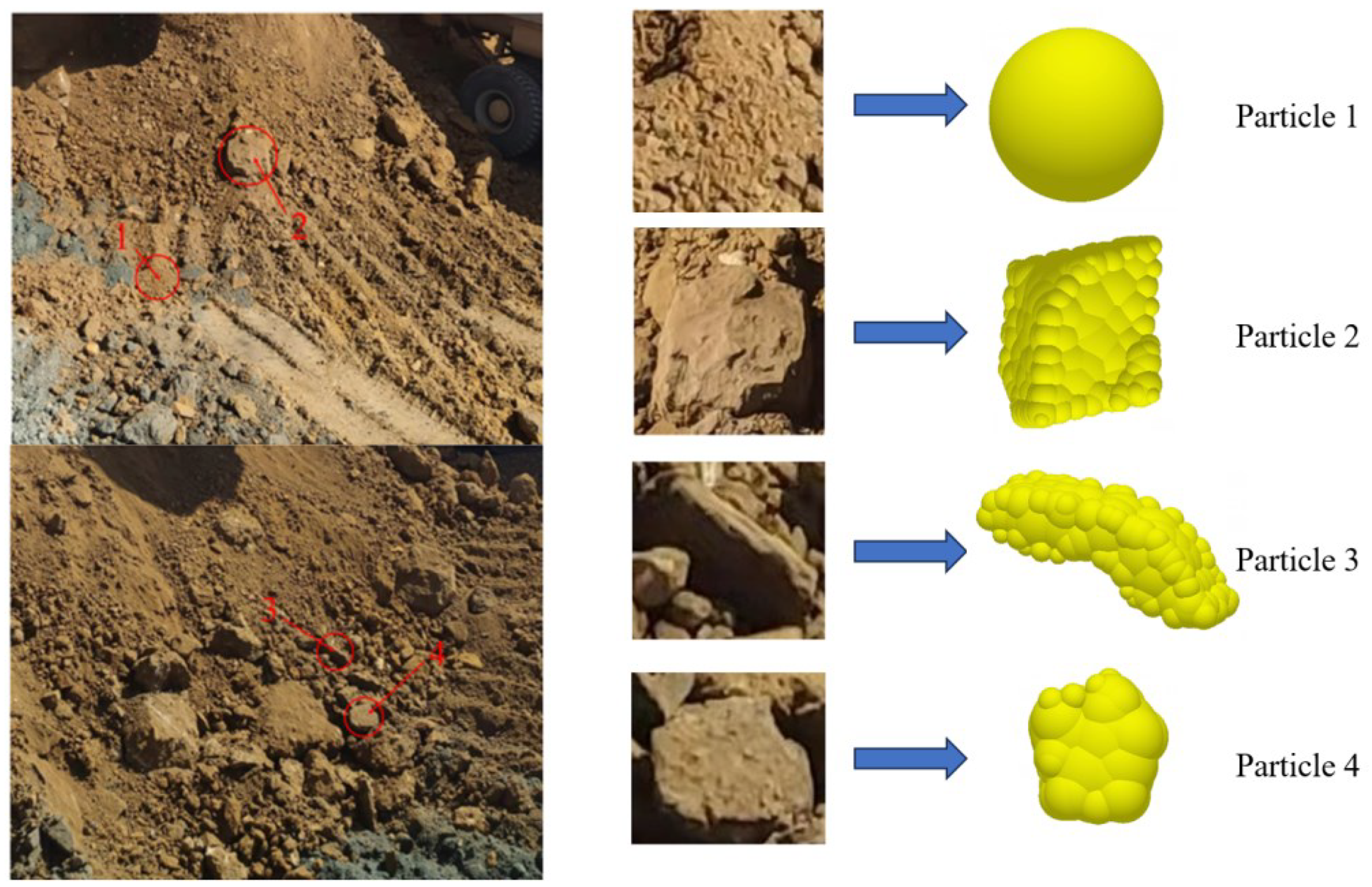
2.1. Construction of Discrete Element Model of Loess Material Pile

The material properties and contact parameters of the buckets and materials were obtained through geological investigation based on typical loess working conditions. As shown in Table 1, the discrete element model of a loess material pile is constructed by using the discrete element software EDEM (EDEM 2020).
According to the actual particle shape of the material, a single ball model was used to simulate small particles (particle size < 50 mm). At the same time, Pro/E was used to establish three-dimensional models of three typical shaped particles (Figure 1), and these were imported into EDEM for material pile filling. The particle size distribution of different shaped particles is shown in Table 2. In the process of loess excavation, each part of the bucket collides with large particles of loess, which breaks the large particles into small particles, and induces wear on the bucket. The larger the particles of loess, the more obvious the fluctuation of bucket excavation resistance.

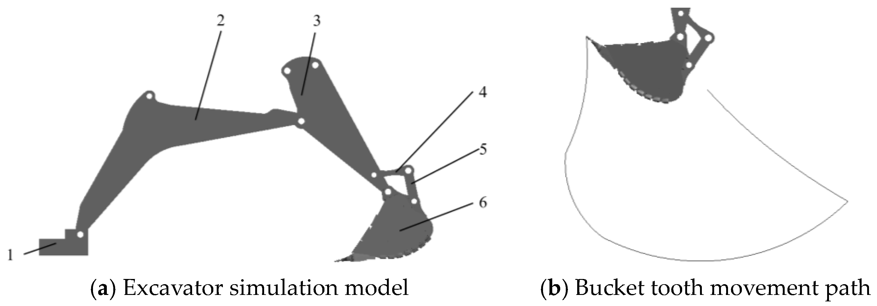
2.2. Construction of Excavator Dynamics Model

The XB120R700 hydraulic excavator model was imported into ADAMS, and the motion pair and drive [18,19] were added to the working device. The STEP function in ADAMS was written to control the arm, bucket rod and bucket to carry out the excavation process according to the preset trajectory. As shown in Figure 2a, the excavator simulation model was composed of operation console (1), arm (2), bucket rod (3), rocker rod (4), link rod (5), and bucket (6).
According to the actual operating experience in different mining work conditions, the simulation trajectory was set in reference to some advice from the technical personnel and the characteristics of the excavator working device. The motion trajectory curve of the bucket teeth from the simulation model is shown in Figure 2b.
The constraints and driving of the excavator working device are shown in Table 3; the excavator console was fixed on the ground, and the arm, bucket rod and bucket were connected through the pin shaft to form a rotating amplitude and jointly control the excavator excavation track.
The settings of the model driving function is shown in Table 4.

2.3. Construction of ADAMS-EDEM Coupling Simulation Model

The 3D model of the excavator working device was imported into EDEM, and the bucket was merged into one component. The material properties were set according to Table 1, and the “acf” command and control file was modified. The coupling simulation file was loaded into ADAMS co-simulation with the coupling simulation file “cosim” and the environmental variables. The ADAMS-EDEM coupling simulation was realized. The coupling simulation model is shown in Figure 3.

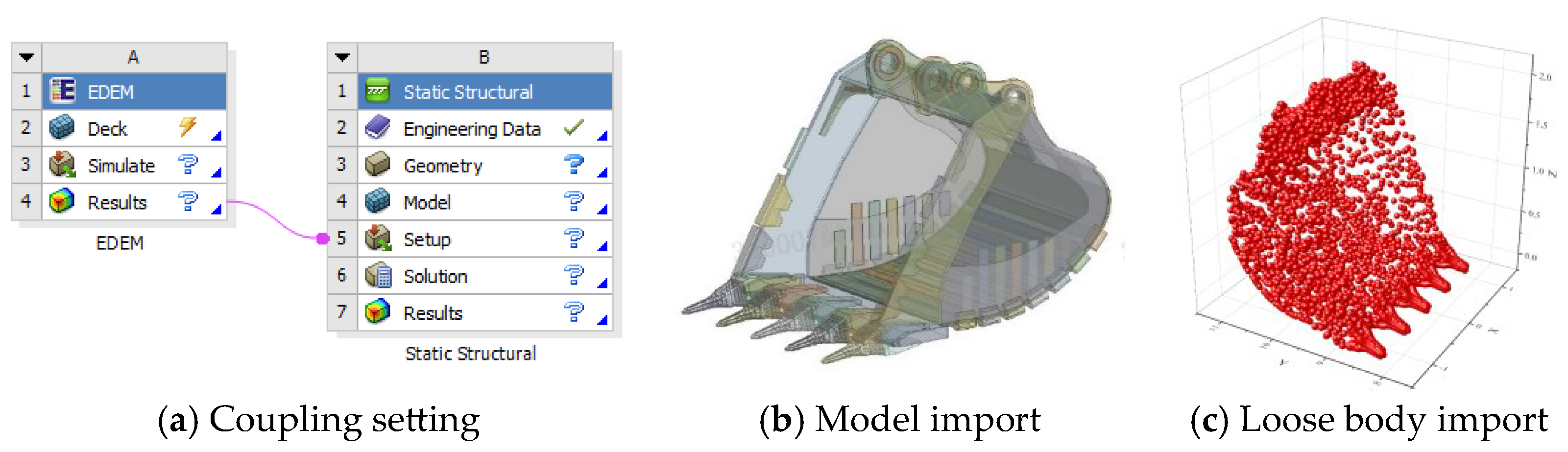
2.4. Construction of ADAMS-EDEM-ANSYS Coupling Simulation Model

An ADAMS-EDEM coupled simulation can only obtain the operating resistance of the bucket under the action of bulk materials. It cannot obtain the mechanical response of the bucket after the action, and the deformation characteristics of the structure cannot be observed. Therefore, in order to analyze the stress and deformation of the bucket during the excavation process, the pressure data of each node at a certain moment in the bucket mining process was saved in a file format that can be read by ANSYS. The digging resistance data was applied to the finite element node (Figure 4a) in the form of loose force, and the static simulation was carried out for this moment (Figure 4c).
As shown in Table 5, the bucket model was assigned Q355 steel material properties. At the hinged parts of the bucket ear plate and bucket rod, the connection holes were bound in fixed support mode and the constraint was set between the contact parts of the bucket to bonded. According to the geometric characteristics of each component and the connection relationship between the components, the method of setting and sizing of each component was used for fine mesh division. Considering the large structural size of the bucket and the limited computer analysis and calculation capacity, tetrahedral mesh was adopted for the insignificant and non-sensitive parts of the bucket. The mesh size of the wear plate, the reinforcement bars of the side plate, and the stiffening plate were set to 20 mm. The mesh size was set to 15 mm for important components such as the buckets, main blade, and ear plate components. The results of the bucket grid division are shown in Figure 5; the overall number of grids is 1,102,155, the number of nodes is 1,750,168, and the average quality of the grid is 0.80203.

3. Analysis of ADAMS-EDEM Coupling Simulation Results

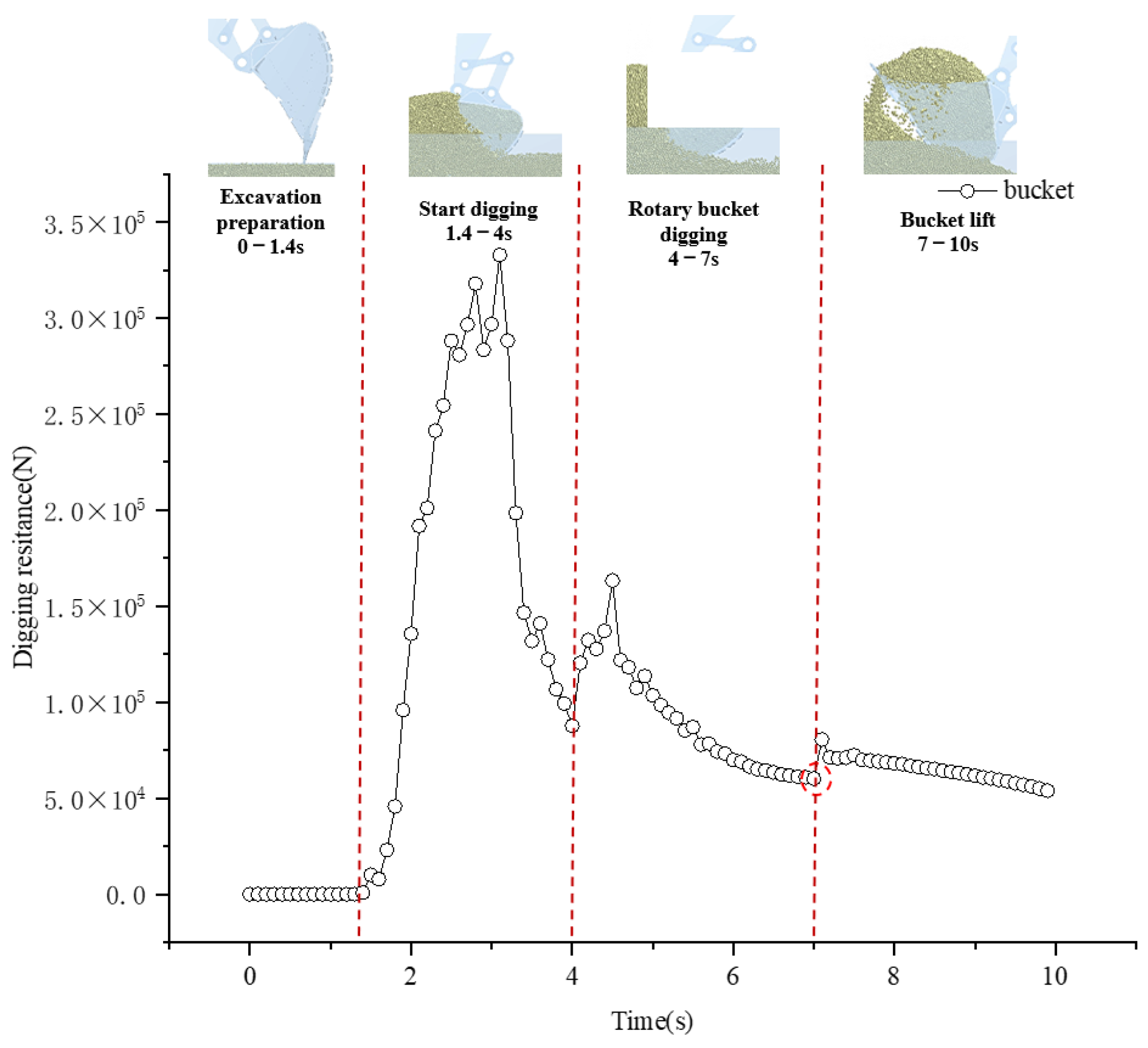
3.1. ADAMS-EDEM Co-Simulation of Mining Process

Through ADAMS-EDEM co-simulation, the digging resistance, filling rate and energy consumption of the bucket during the excavation process were obtained. As shown in Figure 6, the mining excavation process can be divided into four distinctive stages: 1—the arm and bucket rod are lowered (0–1.4 s), the bucket does not contact the material, and the digging resistance is zero; 2—the bucket starts digging, the bucket is inserted into the pile of material and starts spinning (1.4–4 s). As the digging process progresses, the bucket components are subjected to the intermittent impact of discrete materials, and the bucket digging resistance shows an upward trend. The bucket digging resistance reaches the maximum value at 3.1 s, when the bucket is full of materials, and then the digging resistance decreases continuously; 3—the bucket rod stops moving and the bucket rotates around the bucket rod (4–7 s). During the rotation process, the bucket’s angular speed increases from 0 to a fixed value and then starts to rotate at a uniform angular speed. During this process, due to the uneven material gravity and inertial force of the bucket, the mining resistance will inevitably increase under the action of contact impact force during the acceleration process. Then, the bucket gradually fills with materials, and the digging resistance is reduced; 4—the arm and bucket rod are lifted (7–10 s), and the bucket is full of materials. At the time, due to the simultaneous movement of the arm and bucket rod, the digging resistance increases sharply for a short time. After a period of time, the bucket begins to break away from the material pile, and the contact between the bucket and the material pile is reduced. The digging resistance continues to decrease. After the bucket is completely removed from the material pile, the digging resistance of the bucket is the gravity of the materials in the bucket, a few materials fall from the bucket, and the change in digging resistance becomes stable.
As shown in Figure 7, the digging resistance of different components of the bucket during the excavation process can also be obtained through simulation. The digging resistances of the base plate, side plate, bucket teeth and main blade are adjusted on the EDEM post-processing interface, respectively. As shown in Figure 8, the order of digging resistance reduction at different typical positions of the bucket is as follows: the bucket teeth, main blade, side plate and base plate. The overall digging resistance of the bucket is the sum of the digging resistance of all parts of the bucket. In the initial stage of excavation, the bucket teeth first contact the material, and then the side plate, main blade and base plate contact the material. In 0–4 s, the digging resistance of the bucket teeth accounts for the largest proportion of the total digging resistance of the bucket, while the digging resistance of the other parts of the bucket accounts for a relatively small proportion. While the depth of the bucket inserted into the material pile increases, the digging resistance of each bucket component increases. After the bucket is filled with materials, the digging resistance of each bucket component gradually decreases. When the bucket is completely removed from the material pile, the force of the bucket is the gravity of the material in the bucket. At this time, the resistance of the bucket teeth is almost 0, and the main bearing body is the base plate, so the base plate digging resistance is the greatest. In the early stages of the excavation process, the cutting resistance of the tip of the bucket accounts for a large proportion of the digging resistance. In the later stages of the excavation, the bucket’s base plate becomes the main bearing structure because it needs to bear the weight of the loaded materials. The force accounts for a small proportion of the total digging resistance, suggesting that the cutting resistance is an important part of the digging resistance.
The calculation formula of the bucket filling rate is:
    η = V 1 V
As shown in Formula (1), η is the filling rate (%), V1 is the actual load volume of the bucket (m/s), and V is the bucket capacity (m/s). The calculation formula of energy consumption per unit mass material in bucket mining is:
    E = 0 t F v d t m
As shown in Formula (2), E is the energy consumed by mining unit mass materials (J/kg); F is the digging resistance generated during the excavation process; v is the speed during the bucket digging process (m/s); and m is the effective material mass in the bucket after a single excavation (kg). The bucket capacity of the XB120R700 hydraulic excavator is 7 m3, the excavation mass of the original bucket model is 6426.06 kg through discrete element post-processing, and the stacking density of the material pile through geological investigation is 1016.7 kg/m3, so the filling rate of the original bucket is 90.3%. The energy consumption per unit mass material is 413.72 J/kg calculated using ADAMS.

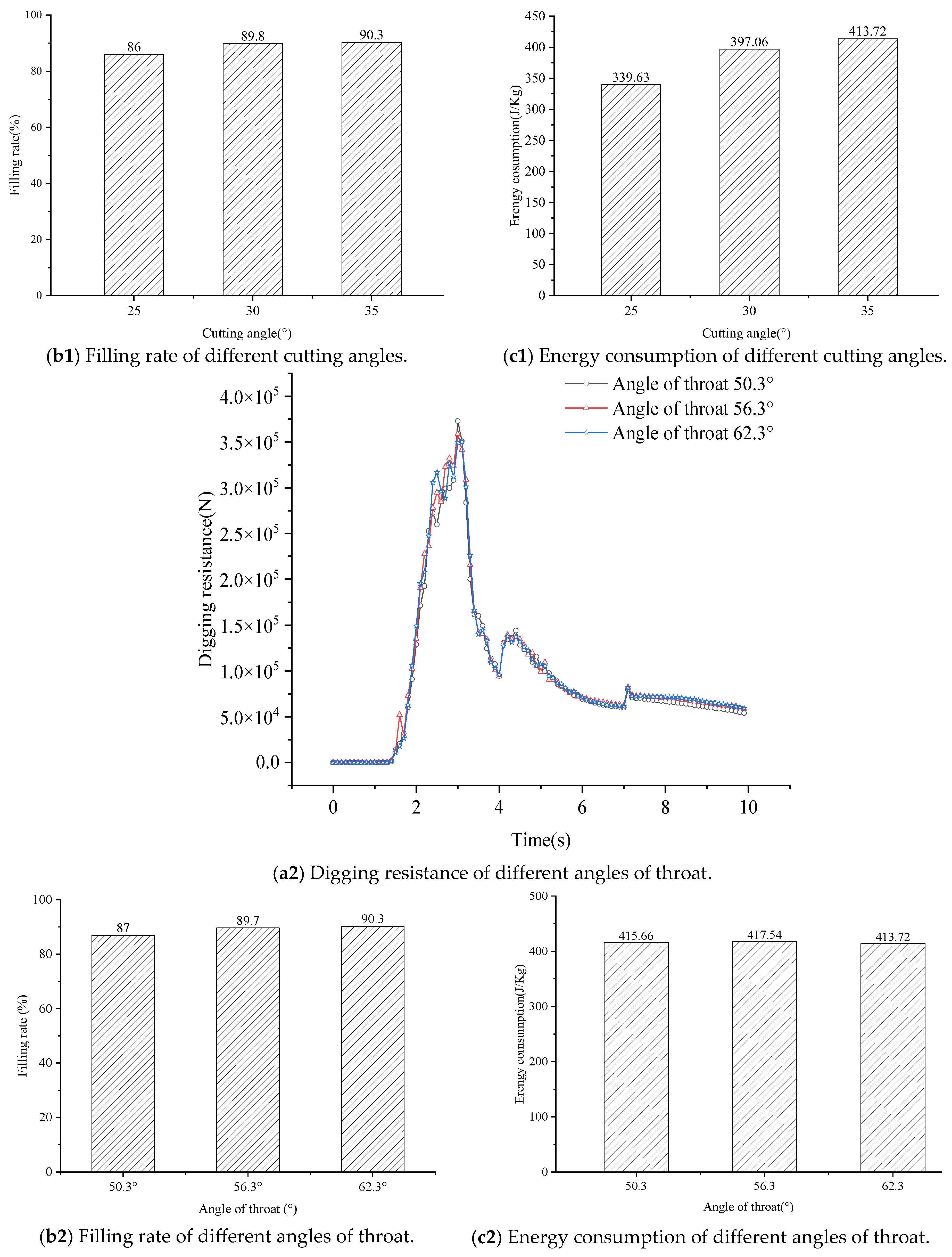
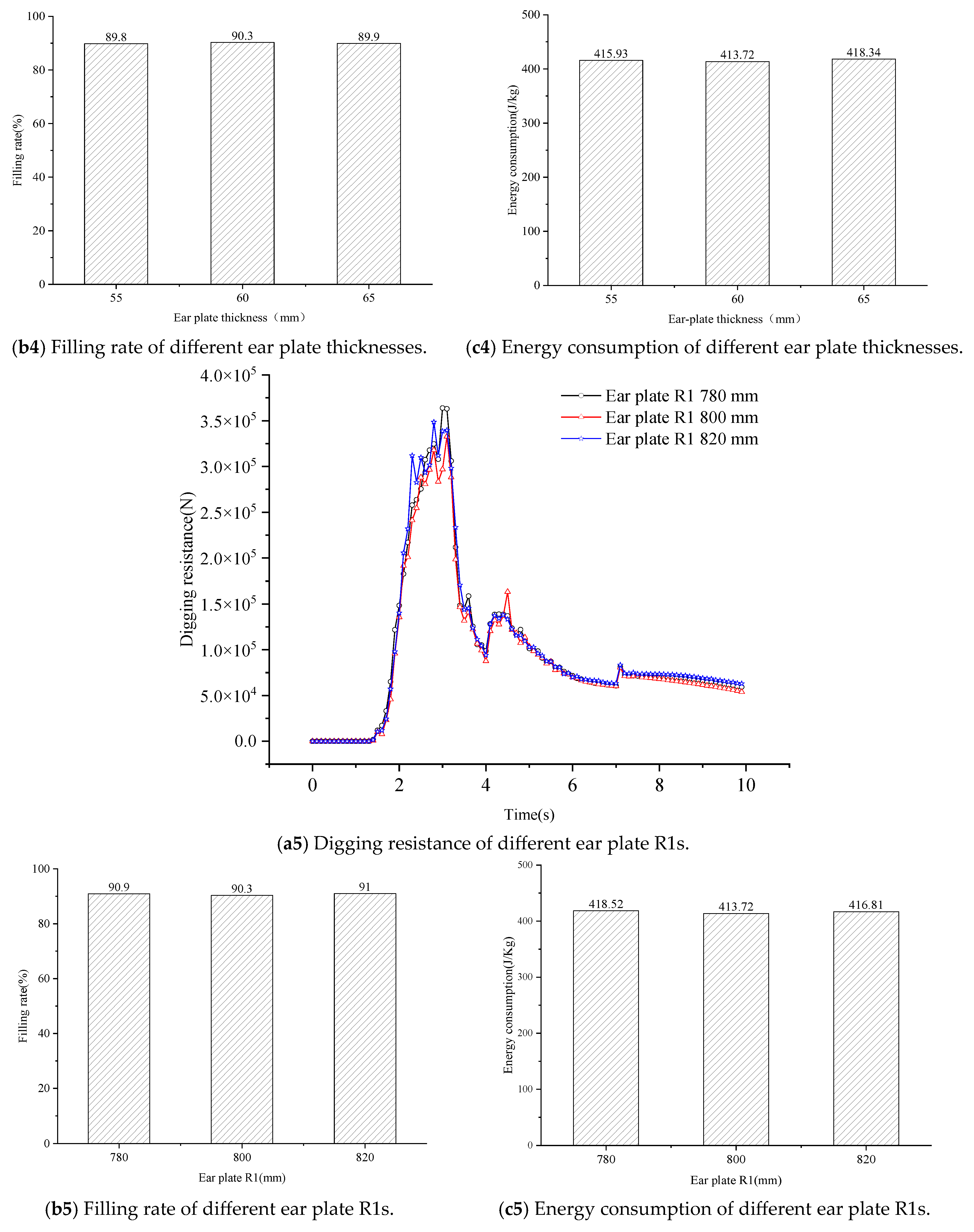
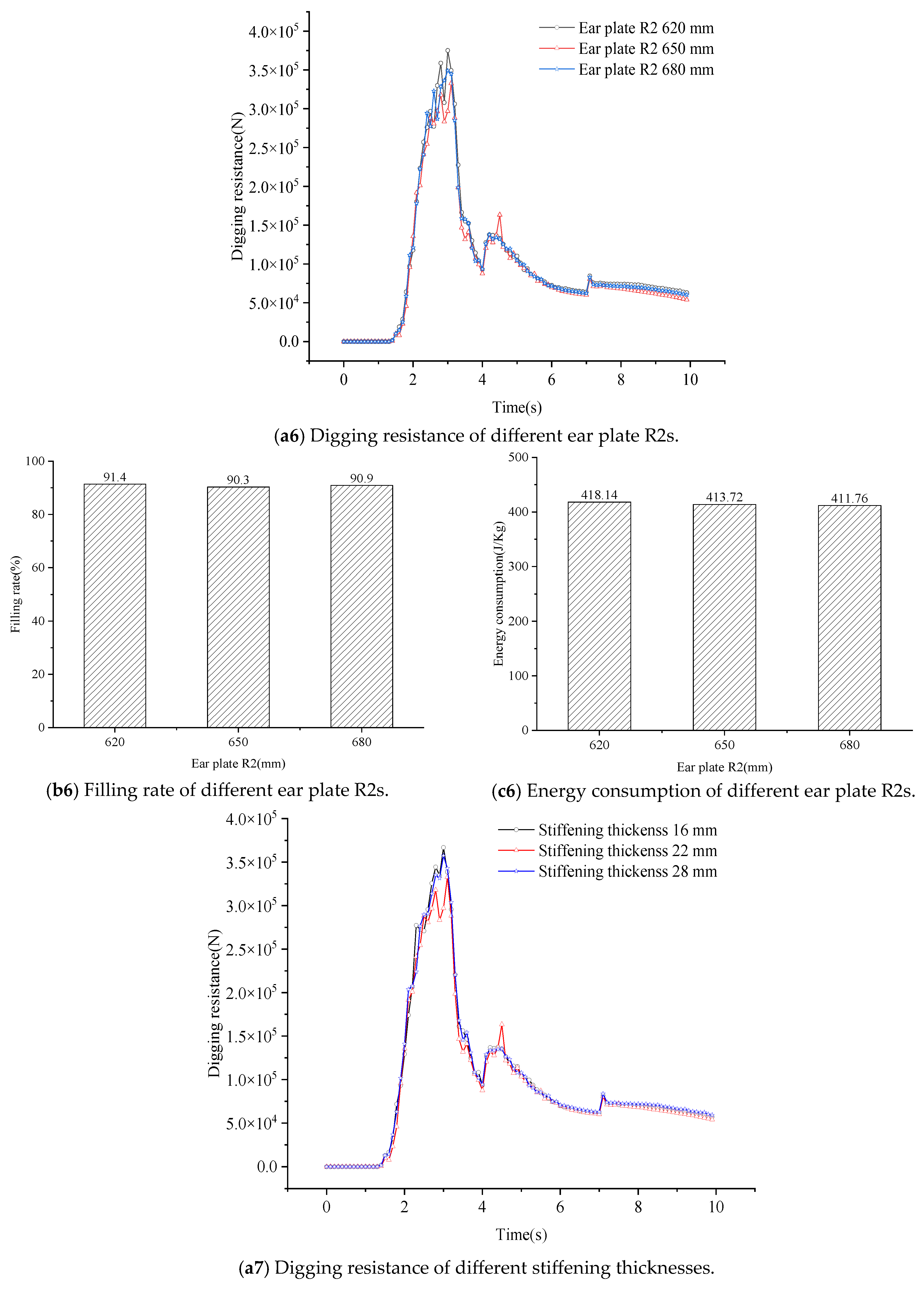
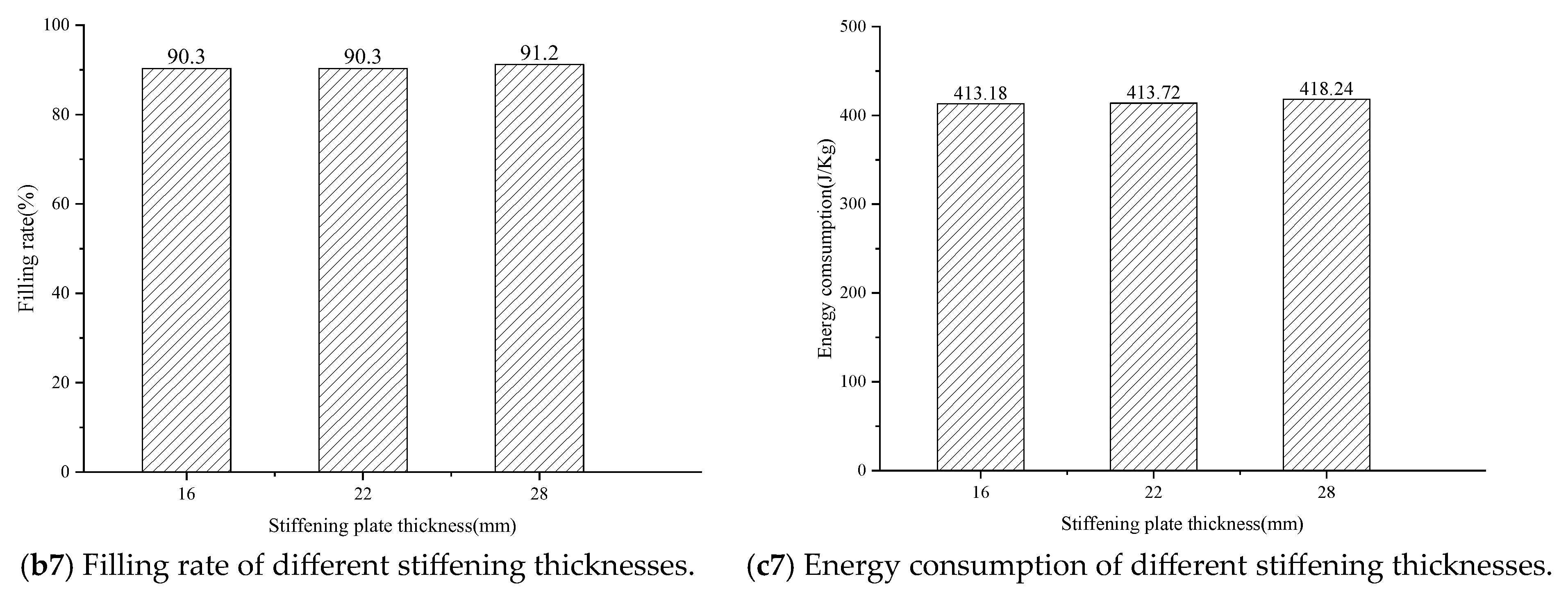
3.2. Influence of Bucket Structure Parameters on Excavation Characteristics

In order to explore the influence of the bucket’s structural parameters on the digging resistance, filling rate and energy consumption of the bucket, the bucket’s structural parameters were changed, and the digging resistance, filling rate and energy consumption of the bucket were compared under different structural parameters. The original model of the main structure of the bucket is shown in Figure 9. Changes in the cutting angle, flare angle and angle of throat of the bucket directly change the bucket’s capacity, and so modify the three bucket structural parameters. In addition, the bucket needs to be connected to the bucket rod through the ear plate, and the excavation resistance of the bucket is transmitted to the ear plate, which can easily cause deformation of the ear plate. Therefore, the structural parameters of the ear plate were also used as an exploration variable. The structural parameters and the changing parameters of the bucket are shown in Table 6, and the comparison of the digging resistance, filling rate and energy consumption of the bucket with different structural parameters is shown in Figure 10.
In Figure 10(a1) Digging resistance of different Cutting angle, as the cutting angle of the bucket increases, the digging resistance of the bucket also increases correspondingly. When the cutting angle reaches 35°, the digging resistance reaches the maximum value. As can be seen from Figure 9b, the cutting angle is the angle between the bucket teeth and its speed direction. The larger the cutting angle, the more material flows into the bucket along the cutting edge bevel, and therefore, the higher the filling rate of the bucket. As can be seen from Figure 10(c1) Energy consumption of different Cutting angle, when the cutting angle is 35°, the energy consumption per unit mass of materials in the bucket during mining also reaches its highest. As shown in Figure 10(b1) Filling rate of different Cutting angle, the change in the angle of the bucket throat has little influence on the digging resistance.
As can be seen from Figure 10(b2) Filling rate of different Angle of throat, the larger the angle of the throat, the higher the bucket filling rate. When the angle of the throat is 62.3°, the bucket filling rate is at its highest. As can be seen from Figure 10(c2) Energy consumption of different Angle of throat, when the angle of the bucket throat reaches 62.3°, the energy consumption per unit mass of materials excavated by the bucket is at its lowest. Considering the digging resistance of the bucket, the filling rate and the energy consumption per unit mass of the bucket, increasing the angle of the bucket throat can not only obtain a higher filling rate, but it can also minimize the energy consumption per unit mass of the bucket.
It can be observed from Figure 10(a3) Digging resistance of different flare angle and Figure 10(c3) Energy consumption of different flare angle that the change of the bucket flare angle has little influence on the digging resistance, but has a large influence on the bucket filling rate. The greater the bucket flare angle, the greater the material quality of the bucket excavation. However, the bucket capacity also increases, that is, the bucket filling rate has no clear relationship with the flare angle of the bucket. As can be seen from Figure 10(c3) Energy consumption of different Flare angle, the energy consumption per unit mass of mining materials is the highest when the bucket flare angle is 10°.
In Figure 6, during the whole excavation process, the bucket ear plate does not have direct contact with the material, and the changes in the bucket’s ear plate structural parameters do not change the articulated position of the bucket rod and the bucket. So, the bucket’s movement trajectory parameters do not change. From Figure 10(a4) Digging resistance of different Ear plate thickness to Figure 10(c7) Energy consumption of different Stiffening thickness, it can be observed that variation in the structural parameters of the bucket’s ear plate have little influence on the filling rate, mining resistance and energy consumption, and the reason for the difference in results is the systematic error of the simulation software.

4. Analysis of EDEM-ANSYS Coupling Simulation Results

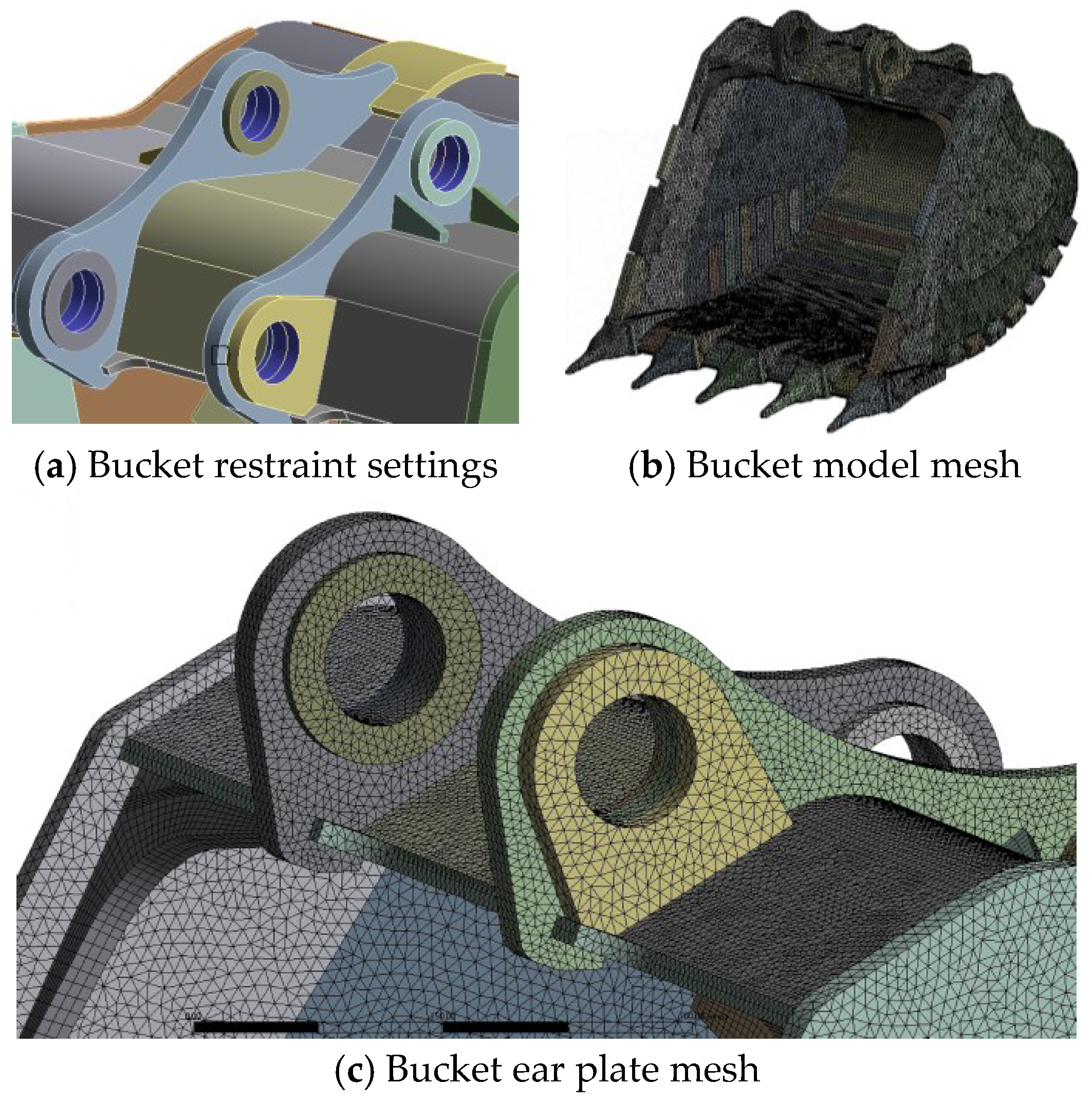
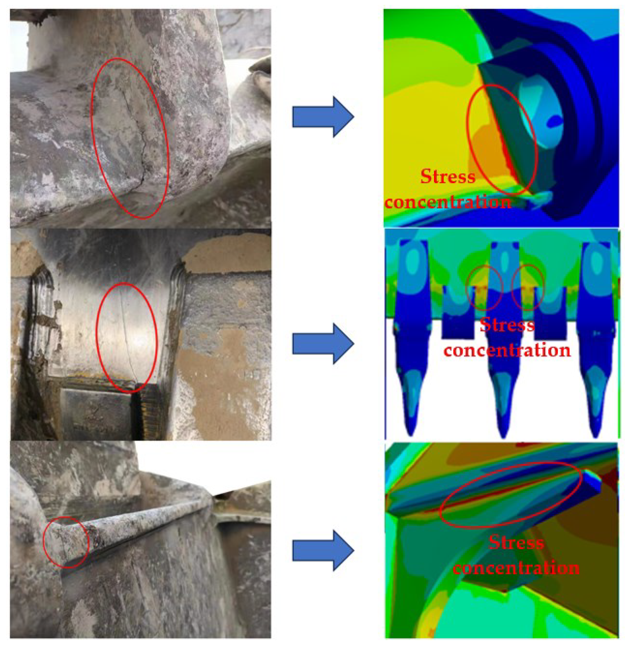
4.1. Finite Element Model Verification

As the main working component of excavators, the bucket has been subjected to harsh working environments for a long time, and there are a variety of complex working conditions. As can be seen from Figure 11, according to the investigation, bucket damage is mainly concentrated in the following three parts: The joint position of the ear plate and the bend plate or top plate, the joint position of the top plate and angle stiffening, and the joint position of the bucket’s tooth root or lip sleeve and the main blade. The probability of damage in the corresponding parts of the bucket during actual working conditions is also large, and the actual damage position is consistent with the high stress position of the finite element model. This indicates that the finite element model can truly reflect the stress deformation and damage of the bucket.

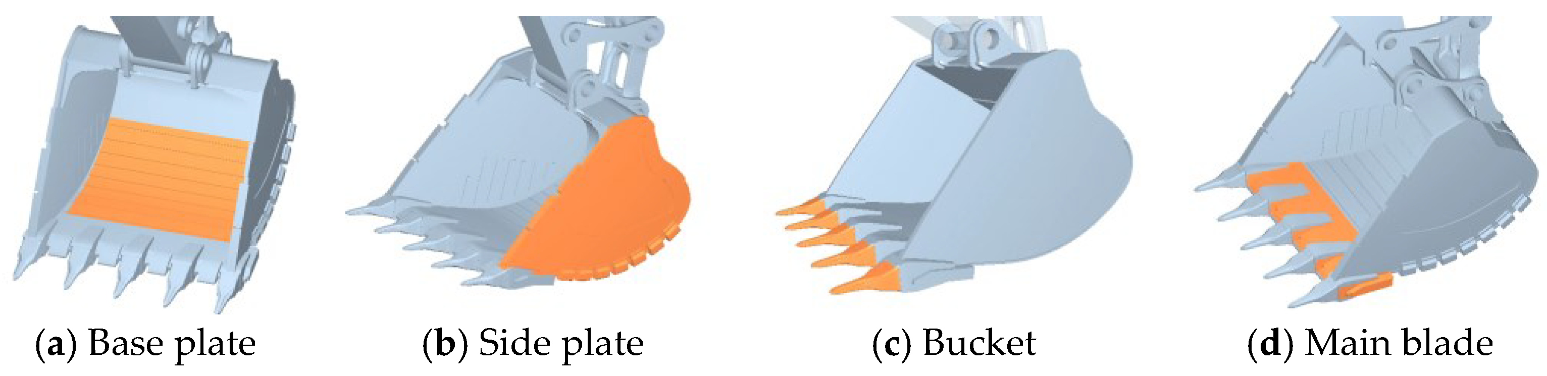
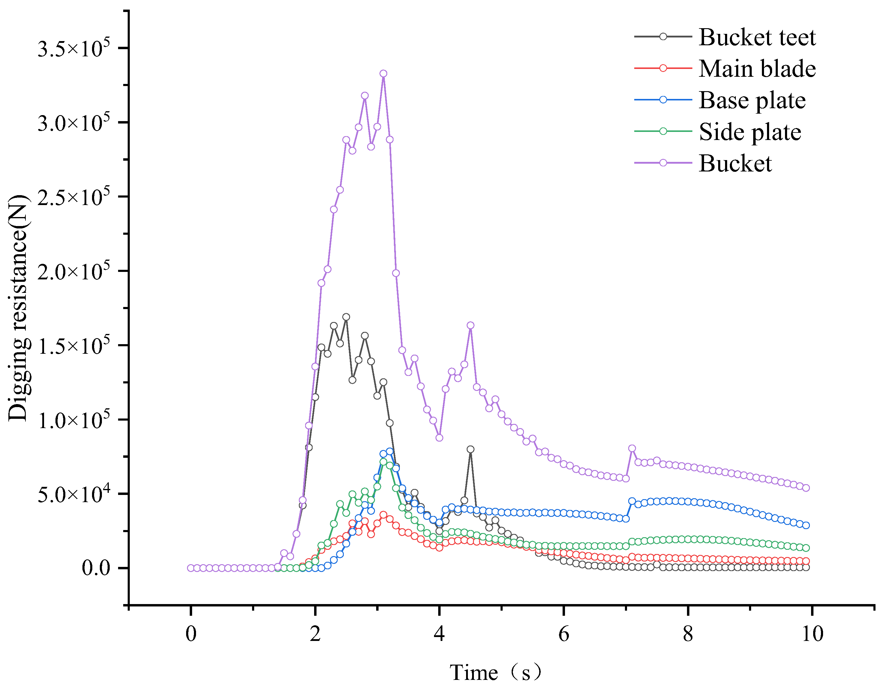
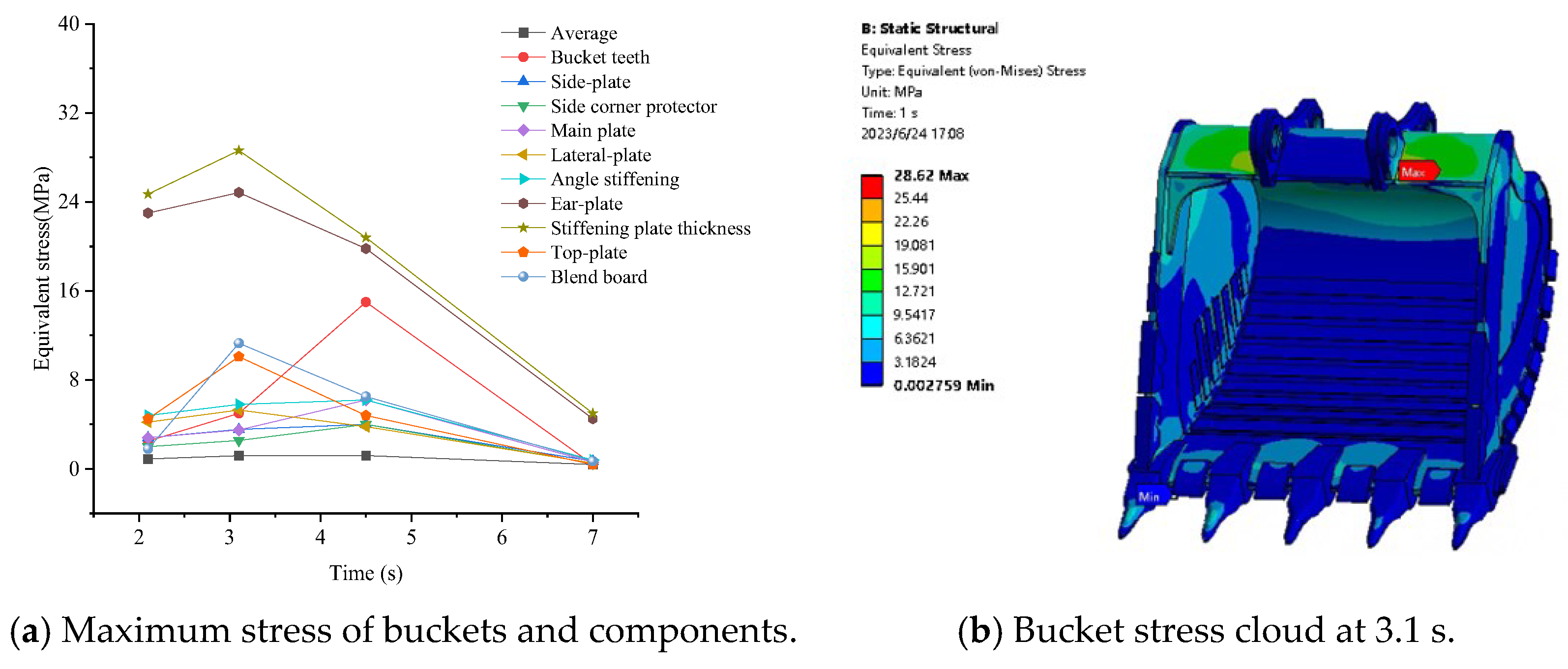
4.2. Stress and Deformation Characteristics of Bucket during Excavation

In order to investigate the change of deformation and stress on the bucket and its components during the excavation process, the loose forces of 2.1 s, 3.1 s, 4.5 s and 7.0 s were introduced into the bucket model for finite element calculation. The maximum deformation and equivalent stress of each bucket component at four digging times were obtained.
Figure 12a shows, during the process of bucket excavation, a comparison of the maximum deformation of each part of the bucket. The maximum deformation of each part of the bucket increases first and then decreases, and reaches its maximum at 3.1 s. At this time, the bucket’s excavation resistance is also at its largest. Comparing the maximum deformation of each bucket component at 3.1 s, it is apparent that the deformation of the bucket teeth, main blade and lateral plate components is larger. After 3.1 s of digging, the three components of the bucket teeth, the main blade and the lateral plate are directly in contact with the material, and withstand the cutting resistance when the material is excavated. The bucket teeth have a smaller force area and are more prone to deformation. In addition, the bucket teeth are installed on the main blade, and the digging resistance of the bucket teeth is transmitted to the main blade through the bucket teeth root, so the main blade is also a large deformation part of the bucket.
In Figure 12b, during the maximum digging resistance at 3.1 s, the deformation is mainly concentrated in the front end of the bucket, such as the bucket teeth, the main blade, the bucker teeth root and other components. The deformation of the middle teeth of the bucket is the largest, followed by the two sides of the bucket teeth, the main blade, the lateral plate and other components.
In Figure 13a, during the process of bucket excavation, the equivalent stress of most components of the bucket presents a trend of first increasing and then decreasing, which is consistent with the change trend of the maximum deformation of each component of the bucket and the digging resistance. The maximum equivalent stress of some components such as the bucket teeth, bend plate and top plate appears at 4.5 s. At the same time, the bucket rod stops moving, the bucket rotates around the bucket rod, and the equivalent stress on the bucket teeth, bend plate and roof reaches its maximum. Comparing the maximum equivalent stress of each part of the bucket, it is apparent that the equivalent stress at the stiffening plate of the ear plate is the largest, followed by the ear plate and the bucket teeth. During the excavation process, the excavation resistance of each bucket component is transmitted to the ear plate, which also causes a concentration of stress at the ear plate. As the auxiliary load-bearing component of the ear plate, the stiffening plate also has a greater excavation resistance, so the stress of the stiffening plate is relatively large.

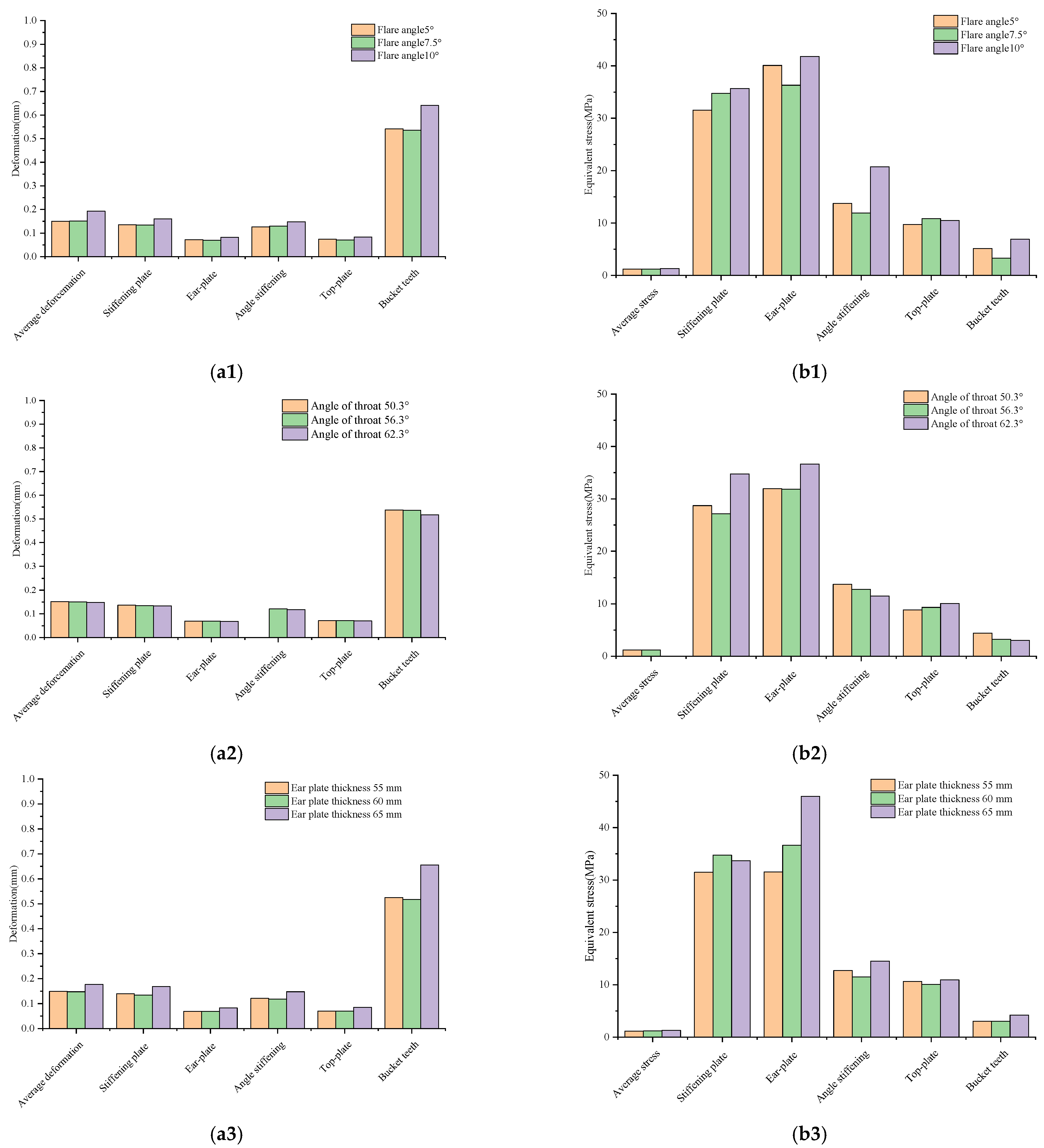
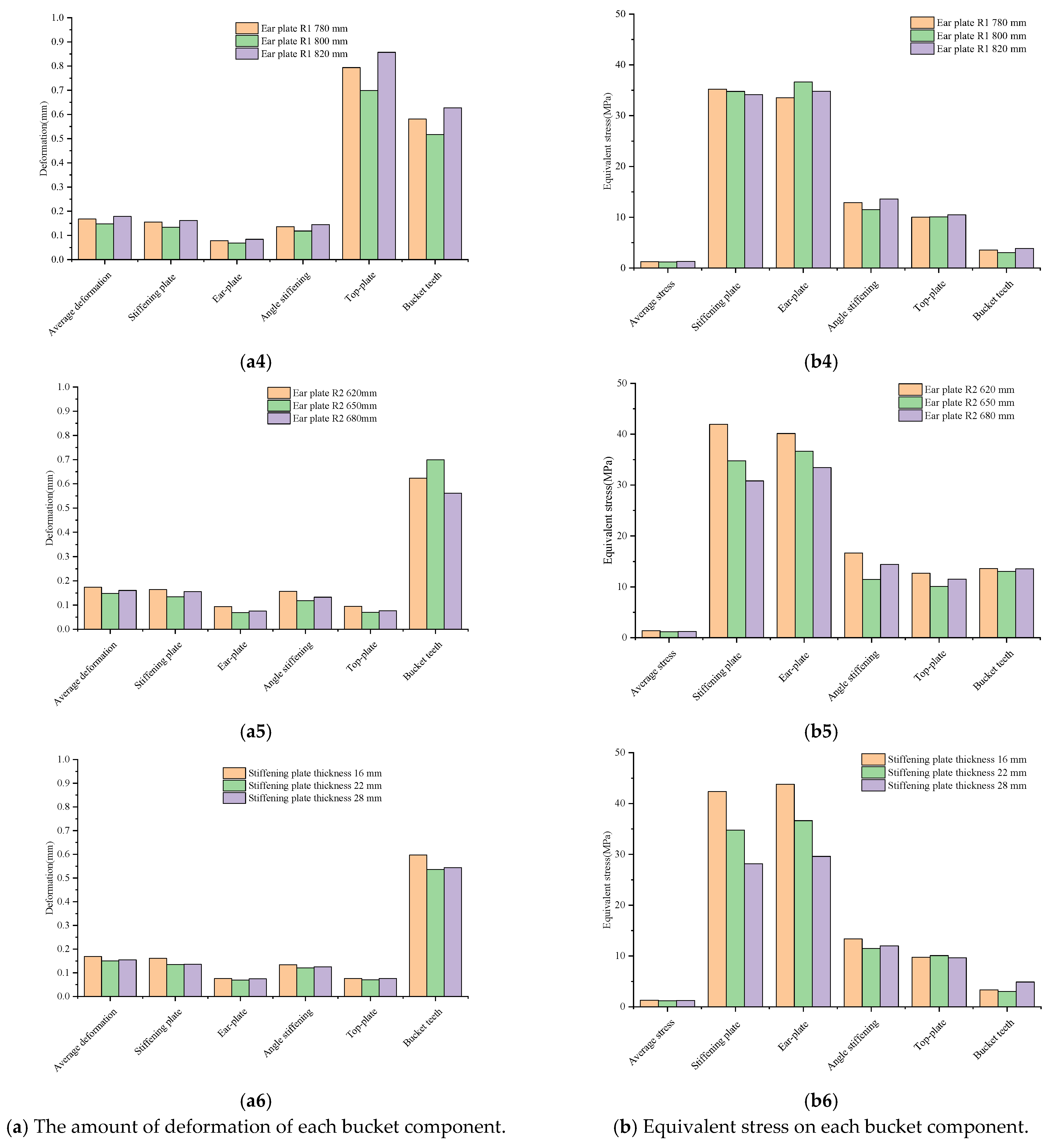
4.3. Influence of Bucket Structure Parameters on Stress and Deformation

As can be seen from Figure 12 and Figure 13, the equivalent stress and deformation of most components of the bucket are large at 3.1 s. As such, the finite element analysis was only carried out for the loose force at the moment of maximum digging resistance. By changing the structural parameters, the influence of the structural parameters on the strain and stress of the bucket can be revealed.
In Figure 10(b3), the quality of the material increases with the increase of the flare angle of the bucket, and the digging resistance of the bucket components also increases. As shown in Figure 14(a1), the deformation of each bucket component increases with the increase of the bucket flare angle, while decreasing the bucket flare angle has little effect on the deformation of the bucket components. As shown in Figure 14(b1), increasing or decreasing the flare angle of the bucket increases the equivalent stress of the bucket. Therefore, the flare angle of the bucket should not be changed.
From Figure 14(a2), increasing or decreasing the angle of the bucket throat has little effect on the components of the bucket. As shown in Figure 14(b2), increasing the angle of the throat of the bucket increases the stress on the ear plate and the stiffening plate, but has little effect on other components of the bucket. Comparing with the stress of the bucket ear plate and the strengthening plate, the increase of stress at the bucket stiffening plate is more obvious.
As shown in Figure 9d, the stiffening plate is located at the end of the ear plate, so the stiffening plate will bear part of the digging resistance. As an auxiliary component of the ear plate, the deformation of the stiffening plate does not affect the connection position of the bucket and the bucket rod, so the stiffening plate can withstand greater stress. Combining the discrete element results and the finite element results, the increase of the angle of throat of the bucket can improve the digging characteristics of the bucket, but does not increase the strain and stress on the components of the bucket.
Although the modification of the structure size of the ear plate has no effect on the ADAMS-EDEM coupling simulation, during the actual production process, the deformation of the ear plate may directly change the hinged position of the bucket and the bucket rod, resulting in the excavator being unable to dig according to the predetermined trajectory that can lead to increased bucket wear and reduced service life.
As can be seen from Figure 14(a3,b3), an increase in the thickness of the ear plate will increase the deformation and stress of each bucket component, while the ear plate and stiffening plate are where the stress is concentrated. Once the deformation occurs, the stress of the ear plate will be uneven, and the failure rate of the ear plate will be accelerated.
It is apparent from Figure 14(a4,b4) that changing the thickness of the stiffening plate has a great influence on the deformation and equivalent stress of each bucket component. Reducing the thickness of the stiffening plate will lead to insufficient strength at the ear plate, and the deformation amount and equivalent stress of the bucket components will be greatly increased. Increasing the thickness of the stiffening plate can effectively reduce the deformation of and equivalent stress on the bucket components.
Considering the discrete element and finite element results, increasing the thickness of the stiffening plate can reduce the deformation of and equivalent stress on the bucket to a certain extent.
This paper explored the influence of a single bucket structural parameter on its mining performance, and then modified and studied multiple bucket structural parameters at the same time. A proposal for a set of optimal bucket parameters is also made. In addition, this method is not limited to mining machinery, and can be applied to other engineering fields.

5. Conclusions

(1)
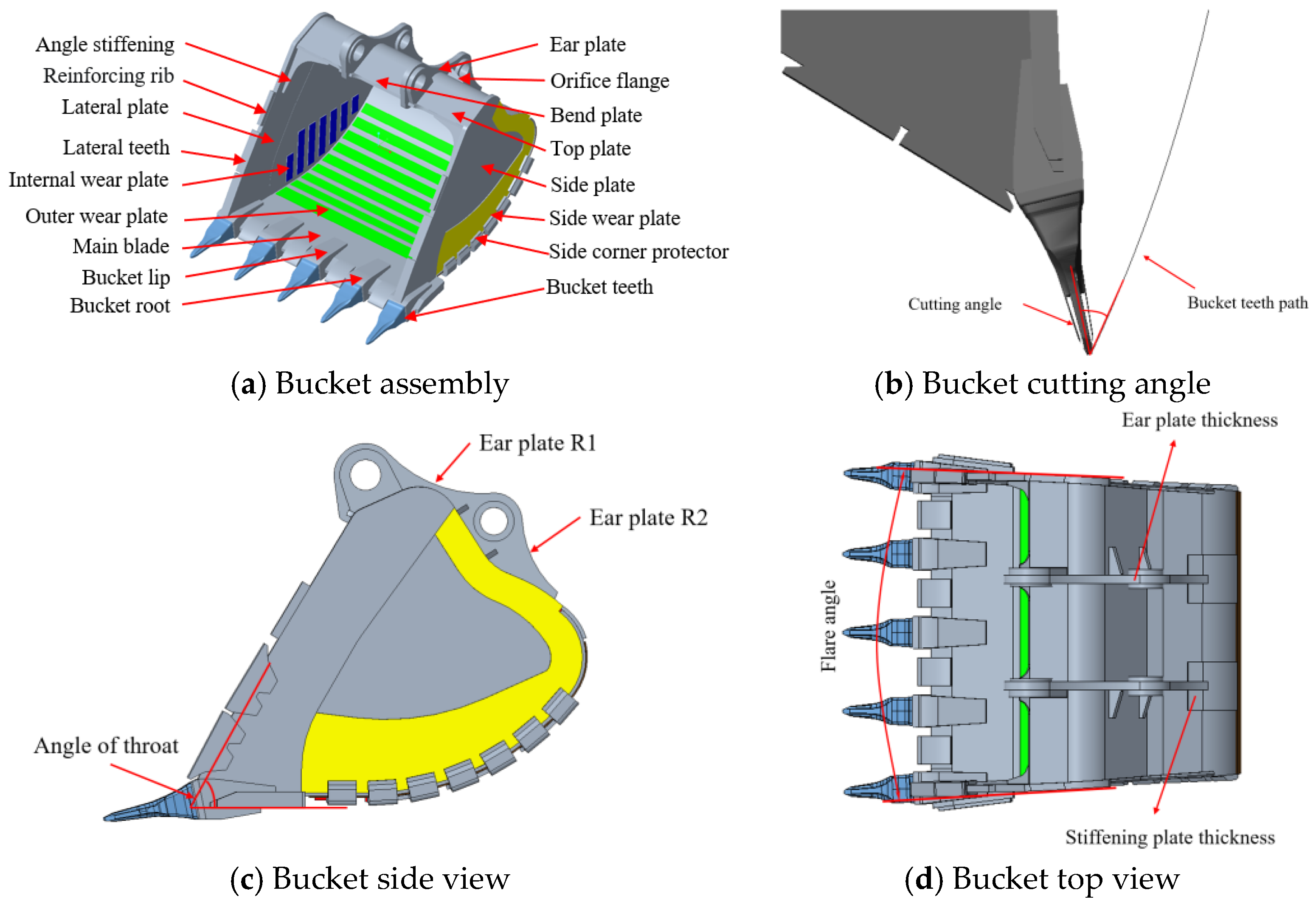
Through EDEM-ADAMS coupling simulation and analysis of the mechanical characteristics of the bucket, a bucket designer can increase the angle of the throat of the bucket to obtain a higher filling rate and minimize the energy consumption per unit mass of materials excavated by the bucket. To some extent, the deformation of and equivalent stress on the whole bucket can be reduced by appropriately reducing the thickness of the ear plate and increasing the thickness of the reinforced plate.
(2)
From the EDEM-ANSYS coupling simulation results, it was found that the finite element model can truly reflect the stress deformation and damage of the bucket. This entails that researchers only need to carry out a finite element analysis of the loose force at the moment of the maximum excavation resistance, which can reveal the influence law of the bucket structural parameters on the bucket strain and stress.
(3)
By reducing the thickness of the ear plate or increasing the thickness of the stiffening plate, one can reduce the digging resistance of the bucket and the energy consumption required for digging, improve the digging efficiency of the bucket, and extend the working life of the bucket.

Author Contributions

Conceptualization, Y.S., Y.W., L.W., L.T., D.W., Z.X. and X.W.; methodology, Y.S., Y.W., L.W., L.T., D.W., Z.X. and X.W.; software, Y.S., L.T., Z.X. and X.W.; validation, C.L., L.T. and X.W.; formal analysis, Y.S. and C.L.; investigation, Y.W.; data curation, Y.S. and Z.X.; writing—original draft, Y.S.; writing—review & editing, L.W. and D.W.; visualization, Y.W., C.L., R.M., M.C., H.C. and W.X.; supervision, L.W., C.L., D.W., R.M., M.C., H.C. and W.X.; project administration, D.W.; funding acquisition, D.W. All authors have read and agreed to the published version of the manuscript.

Funding

The research was supported by the project from CUMT-XCMG Mining Intelligent Equipment Technology Research Institute (Grant no. 2020050049 2202).

Informed Consent Statement

Not applicable.

Data Availability Statement

Data will be made available on request.

Conflicts of Interest

We declare that we have no financial and personal relationships with other people or organizations that can inappropriately influence our work, there is no professional or other personal interest of any nature or kind in any product, service and/or company that could be construed as influencing the position presented in, or the review of, the manuscript entitled.

References

  1. Velikanov, V.S.; Kozyr, A.V.; Dyorina, N.V. Engineering Implementation of View Objectives in Mine Excavator Design. Procedia Eng. 2017, 206, 1592–1596. [Google Scholar] [CrossRef]
  2. Wen, L.; Kim, D.; Liu, M.; Lee, S. 3D Excavator Pose Estimation Using Projection-Based Pose Optimization for Contact-Driven Hazard Monitoring. J. Comput. Civ. Eng. 2023, 37, 04022048. [Google Scholar] [CrossRef]
  3. Iwata, H.; Yu, S.; Mizushima, S.; Yamamura, S. Design of a Discrete Element Method Parameter Identification System for the Efficient Excavation of Mining Shovels Based on Digging resistance Analysis. Int. J. Mech. Eng. Robot. Res. 2022, 11, 304–310. [Google Scholar] [CrossRef]
  4. Ren, Z.; Li, J.; Pang, X.; Liu, J.; Li, T.; Yu, S. Research on the matching characteristics of the theoretical digging force of a backhoe hydraulic excavator. Sci. Rep. 2022, 12, 16181. [Google Scholar] [CrossRef] [PubMed]
  5. He, J.L.; Zheng, H.H.; Li, D. The Calculation for Digging-Resistance of Small-Scale Excavator Based on Torque Method. Appl. Mech. Mater. 2013, 456, 248–251. [Google Scholar] [CrossRef]
  6. Jiang, Y.Z.; Liao, G.W.; Zhu, S.S.; Hu, Y.F. Investigation on cutting resistance characteristic of bucket wheel excavator using DEM and DOE methods. Simul. Model. Pract. Theory 2021, 111, 102339. [Google Scholar] [CrossRef]
  7. Brînaș, I.; Andraș, A.; Radu, S.M.; Popescu, F.D.; Andraș, I.; Marc, B.I.; Cioclu, A.R. Determination of the Bucket Wheel Drive Power by Computer Modeling Based on Specific Energy Consumption and Cutting Geometry. Energies 2021, 14, 3892. [Google Scholar] [CrossRef]
  8. Tomatsu, T.; Nonaka, K.; Sekiguchi, K.; Suzuki, K. Digging Soil Experiments for Micro Hydraulic Excavators based on Model Predictive Tracking Control. J. Phys. Conf. Ser. 2016, 744, 012067. [Google Scholar] [CrossRef]
  9. Sarkar, M.; Ghosh, S.K.; Mukherjee, P. Analysis of wear generation in mine excavator bucket. Ind. Lubr. Tribol. 2015, 67, 52–58. [Google Scholar] [CrossRef]
  10. Gan, J.; Zhou, Z.; Yu, A.; Ellis, D.; Attwood, R.; Chen, W. Co-simulation of multibody dynamics and discrete element method for hydraulic excavators. Powder Technol. 2023, 414, 118001. [Google Scholar] [CrossRef]
  11. Sun, H.; Ren, Z.; Wang, J.; Wei, W.; Liang, Y.; Feng, M. Integrated expression and general optimisation method of bucket shapeline of backhoe hydraulic excavator. J. Mech. Sci. Technol. 2021, 35, 2543–2550. [Google Scholar] [CrossRef]
  12. Yu, X.; Pang, X.; Zou, Z.; Zhang, G.; Hu, Y.; Dong, J.; Song, H. Lightweight and High-Strength Design of an Excavator Bucket under Uncertain Loading. Math. Probl. Eng. 2019, 2019, 3190819. [Google Scholar] [CrossRef]
  13. Wang, C.H.; Gao, Y.; Zhang, Y.Y.; Li, C.L. Dynamic Characteristics of the Backhoe Excavator Bucket Based on Pro/E and ANSYS. Adv. Mater. Res. 2012, 619, 30–33. [Google Scholar] [CrossRef]
  14. Long, Y.; Yang, L.; Li, Y. Load Law Analysis and Fatigue Life Prediction for Bucket Teeth of Excavator Working Device. In Proceedings of the 2022 IEEE 17th Conference on Industrial Electronics and Applications (ICIEA), Chengdu, China, 16–19 December 2022; pp. 1322–1327. [Google Scholar] [CrossRef]
  15. Nezami, E.G.; Hashash, Y.M.A.; Zhao, D.; Ghaboussi, J. Simulation of front end loader bucket–soil interaction using discrete element method. Int. J. Numer. Anal. Methods Geomech. 2007, 31, 1147–1162. [Google Scholar] [CrossRef]
  16. Coetzee, C.J.; Els, D.N.J. The numerical modelling of excavator bucket filling using DEM. J. Terramech. 2009, 46, 217–227. [Google Scholar] [CrossRef]
  17. Coetzee, C.J.; Els, D.N.J. Calibration of granular material parameters for DEM modelling and numerical verification by blade–granular material interaction. J. Terramech. 2009, 46, 15–26. [Google Scholar] [CrossRef]
  18. She, Y.N.; Ning, X.B.; Lin, Q. Kinematics Performance Simulation and Optimization of Large Face-Shovel Hydraulic Excavator Working Device Based on ADAMS. Appl. Mech. Mater. 2013, 271–272, 996–1000. [Google Scholar] [CrossRef]
  19. Ji, S.; Liang, S. DEM-FEM-MBD coupling analysis of landing process of lunar lander considering landing mode and buffering mechanism. Adv. Space Res. 2021, 68, 1627–1643. [Google Scholar] [CrossRef]
Figure 1. Loess particle model.
Applsci 13 11507 g001
Figure 2. Excavator dynamics model. Console (1); arm (2); bucket rod (3); rocker rod (4); link rod (5); bucket (6).
Applsci 13 11507 g002
Figure 3. ADAMS-EDEM coupling simulation model.
Applsci 13 11507 g003
Figure 4. Model and loose force import.
Applsci 13 11507 g004
Figure 5. Bucket constraint settings and meshing.
Applsci 13 11507 g005
Figure 6. Bucket digging resistance.
Applsci 13 11507 g006
Figure 7. Bucket area division.
Applsci 13 11507 g007
Figure 8. Digging resistance in different areas of the bucket.
Applsci 13 11507 g008
Figure 9. Bucket structure diagrams.
Applsci 13 11507 g009
Figure 10. Influence of bucket structural parameters on excavation performance.
Applsci 13 11507 g010aApplsci 13 11507 g010bApplsci 13 11507 g010cApplsci 13 11507 g010dApplsci 13 11507 g010eApplsci 13 11507 g010f
Figure 11. Bucket’s actual damage and high stress corresponding position.
Applsci 13 11507 g011
Figure 12. The deformation of buckets and components at different times.
Applsci 13 11507 g012
Figure 13. The stress distribution of the bucket and its components at different times.
Applsci 13 11507 g013
Figure 14. Influence of bucket structural parameters on stress and deformation. (a1) Influence of Flare angle on the deformation of various components of the bucket, (b1) Influence of Flare angle on the stress of various components of the bucket, (a2) Influence of Angle of throat on the deformation of various components of the bucket, (b2) Influence of Angle of throat on the stress of various components of the bucket, (a3) Influence of Ear plate thickness on the deformation of various components of the bucket, (b3) Influence of Ear plate thickness on the stress of various components of the bucket, (a4) Influence of Ear plate R1 on the deformation of various components of the bucket, (b4) Influence of Ear plate R1 on the stress of various components of the bucket, (a5) Influence of Ear plate R2 on the deformation of various components of the bucket, (b5) Influence of Ear plate R2 on the stress of various components of the bucket, (a6) Influence of Stiffening plate thickness on the deformation of various components of the bucket, (b6) Influence of Stiffening plate thickness on the stress of various components of the bucket.
Applsci 13 11507 g014aApplsci 13 11507 g014b
Table 1. Material properties and contact parameters.
Material PropertiesLoessBucket
Poisson’s ratio0.410.28
Shear modulus (MPa)10206,000
Density (kg/m3)16807850
Contact parametersloess-loessloess-bucket
Coefficient of restitution0.60.5
Coefficient of static friction0.390.5
Coefficient of rolling friction0.110.05
Table 2. The size distribution of loess particles.
Particle TypeParticle 1Particle 2Particle 3Particle 4
Particle size/mm<5050–100100–200>200
Mass distribution70%15%10%5%
Table 3. The model constraints and drive of excavator simulation.
TypeConstraintMotion
Fixed pairconsole-ground
Revolute pairarm-consolerotation driving
Revolute pairbucket rod-armrotation driving
Revolute pairrocker rod-bucket rodrotation driving
Revolute pairlink rod-rocker rod
Revolute pairbucket-link rod
Revolute pairbucket-bucket rod
Table 4. ADAMS model driving function settings.
Type of Revolute PairDriving Function
arm-consoleSTEP (time, 0, 0, 1, −25 d) + STEP (time, 7, 0, 10, −30 d)
bucket rod-armSTEP (time, 0, 0, 1, 26 d) + STEP (time, 1, 0, 4, −72 d)
rocker rod-bucket rodSTEP (time, 0, 0, 1, 57 d) + STEP (time, 4, 0, 7, −48 d) + STEP (time, 7, 0, 10, −17 d)
Table 5. Q355 steel material properties table.
ParameterElasticity Modulus (N/m2)Poisson’s RatioDensity (kg/m3)Yield Strength (MPa)
Value2.06 × 10110.287.85 × 103355
Table 6. Structural parameters of the original bucket model.
Bucket
Structure
Cutting Angle
(°)
Angle of Throat
(°)
Flare Angle
(°)
Ear Plate Thickness
(mm)
Ear Plate R1 (mm)Ear Plate R2 (mm)Stiffening Plate Thickness
(mm)
Original parameter3056.37.56065080022
Variation parameter2550.355562078016
3562.3106568082028
Disclaimer/Publisher’s Note: The statements, opinions and data contained in all publications are solely those of the individual author(s) and contributor(s) and not of MDPI and/or the editor(s). MDPI and/or the editor(s) disclaim responsibility for any injury to people or property resulting from any ideas, methods, instructions or products referred to in the content.

