Article

Reliability Analysis of a Three-Engine Simultaneous Pouring Control System Based on Bayesian Networks Combined with FMEA and FTA

School of Mechanical Engineering, Inner Mongolia University of Technology, Hohhot 010051, China
*
Author to whom correspondence should be addressed.
Appl. Sci. 2023, 13(20), 11546; https://doi.org/10.3390/app132011546
Submission received: 6 September 2023 / Revised: 12 October 2023 / Accepted: 19 October 2023 / Published: 21 October 2023

Abstract

:
Pouring is an important process in the production of solid propellant rocket engines, and usually, the cost of a solid propellant rocket engine is extremely high. Therefore, pouring production with high reliability is very important. The pouring of three engines of solid propellant rocket engines simultaneously can greatly improve its production efficiency. However, it makes the system more complex and redundant. For a multi-state system, it is difficult to make an accurate evaluation of system reliability. Aiming at the redundancy of multiple engines and acousto-optic combined control in the three-engine simultaneously slurry pouring alarm control system with dissimilar redundant alarm units, a reliability analysis method is proposed based on the combination of Failure Mode Effect Analysis (FMEA) and Fault Tree Analysis (FTA). The control system is divided into several redundant states according to the alarm function, and then the Bayesian Networks method is used for reliability evaluation and calculation. Finally, the reliabilities of systems with dissimilar redundancy degrees are obtained. The tangible results of this research work are as follows: (1) The research results obtained by applying the FMEA method laid a foundation for the establishment of a fault trees model for analyzing the reliability of the control system using the FTA method, in addition, which can guide the maintenance and fault identification of the control system during engineering application. (2) The calculated value of the reliability of the control system is 0.999989, and the mean time between failures is MTBF is 5 × 10⁴ by using the fault tree analysis method, which proves that the designed three-engine simultaneous pouring system is very reliable. (3) Based on the calculation and comparison of the Bayesian Networks of redundant three-engine pouring control systems, the circuit diagram of the improved control system is identified.

1. Introduction

Owing to the high-quality requirements and high manufacturing cost of solid propellant rocket engine products, the high reliability of automatic control charging equipment is very important for the production of solid propellant rocket engines [1]. Because of the long production cycle of the pouring process and low efficiency, the pouring process of a single engine cannot meet the demand for high efficiency for larger batches of production. The pouring of three solid propellant rocket engines simultaneously can greatly improve production efficiency. At the same time, the high reliability of the control system is an important guarantee of pouring work, which can reduce or avoid economic losses caused by pouring failure and explosion accidents caused by cleaning up residues. Therefore, the reliability analysis of the three-engine simultaneous pouring control system is very important.
Nowadays, many scholars have focused on reliability analysis and its applications. Reliability-based multidisciplinary design optimization (RBMDO) has been widely acknowledged for the design problems of modern complex engineering systems. Some of the issues with RBMDO are reviewed in references [2,3,4,5]. In reference [6], the saddle point approximate reliability analysis method is introduced, and the collaborative optimization method is combined to solve the uncertainty problem. Reliability analysis methods such as Fault Tree Analysis (FTA), Failure Mode and Effect Analysis (FMEA), Reliability Block Diagram (RBD), and Markov Models have been widely used in rolling stock [7]. Reference [8] describes a reliability analysis method called AKMP, which is used to evaluate the failure probability of mechanical structures. This method utilizes multi-point sampling and active learning, which combines the GA-Halton sequence and a new learning function, FELF, to update the model. The results show that the AKMP method has good accuracy and efficiency. However, the application of these methods to the solid propellant rocket engine pouring control system is very limited.
Failure mode and effect analysis (FMEA) is used to proactively identify product failures and provide preventive measures to eliminate or reduce failures [9]. The traditional risk priority number (RPN) method has been criticized for having many deficiencies, and various risk priority models have been proposed to enhance the performance of FMEA [10]. Failure mode and effects analysis (FMEA) has been extensively used for examining potential failures in products, processes, designs, and services in reference [11], the risk factors such as the occurrence O, severity S, and detection D of each failure mode in the traditional FMEA are treated as fuzzy variables and evaluated by using fuzzy linguistic terms and fuzzy ratings. As a result, fuzzy risk priority numbers (FRPNs) are proposed for the prioritization of failure modes. In terms of the possibilities of failure of bottom events, an algorithm of the intuitionistic fuzzy fault-tree analysis is proposed to calculate the fault interval of system components and to find the most critical system component for managerial decision-making based on some basic definitions [12]. To improve the performance of the FMEA method, some FMEA-based approaches are proposed to integrate the advantages of the Fault Tree Analysis (FTA) and FMEA [13,14]. In Ref. [15], a fault tree for calculating the reliability of combinatorial logic circuits associated with single and multiple faults was proposed.
In order to maximize system reliability, the redundancy strategy, i.e., the active or standby redundancy of each k-out-of-n subsystem in the traditional problem, was determined [16], and the door redundancy was also introduced to improve the reliability of each digital logic gate. In order to improve the reliability and safety of an actuation system, dissimilar redundancy technology has been adopted in modern aircraft design [17]. In reference [18], based on the design optimization under mixed uncertainty, a new kriging model is proposed to solve the design optimization problem of time-varying reliability with flexible constraints. In reference [19], a subregion computing strategy is proposed, and a new learning function is introduced, which can effectively improve the computing efficiency of time-varying reliability. In reference [20], a new coupled Kriging model is proposed to balance computational costs and accurate results.
In this paper, an FMEA table for determining the important components of the control system is established. The FMEA and FTA are combined to analyze the reliability of a three-engine simultaneous pouring control circuit system. Based on the established FMEA table, the system is qualitatively and quantitatively analyzed by using FTA. The redundant design of the alarm function can improve the reliability of the control system significantly. However, many redundancies will lead to high cost, complexity, and maintenance difficulties. In order to reasonably evaluate the reliability of an alarm control system with dissimilar redundancies, the control system is divided into several redundant states according to the alarm function, and then Bayesian Networks analysis is applied to obtain the most suitable system redundancy design. The production cost of the solid rocket engine involved is very high. Although the simultaneous pouring of three solid rocket engines greatly improves the production efficiency, the loss is more serious once the pouring fails, so it is more required to ensure particularly high reliability in the production process. In order to ensure this problem, this paper focuses on the reliability of the design of the three-engine simultaneously pouring control system and the rationality of the redundant design of the designed control system.

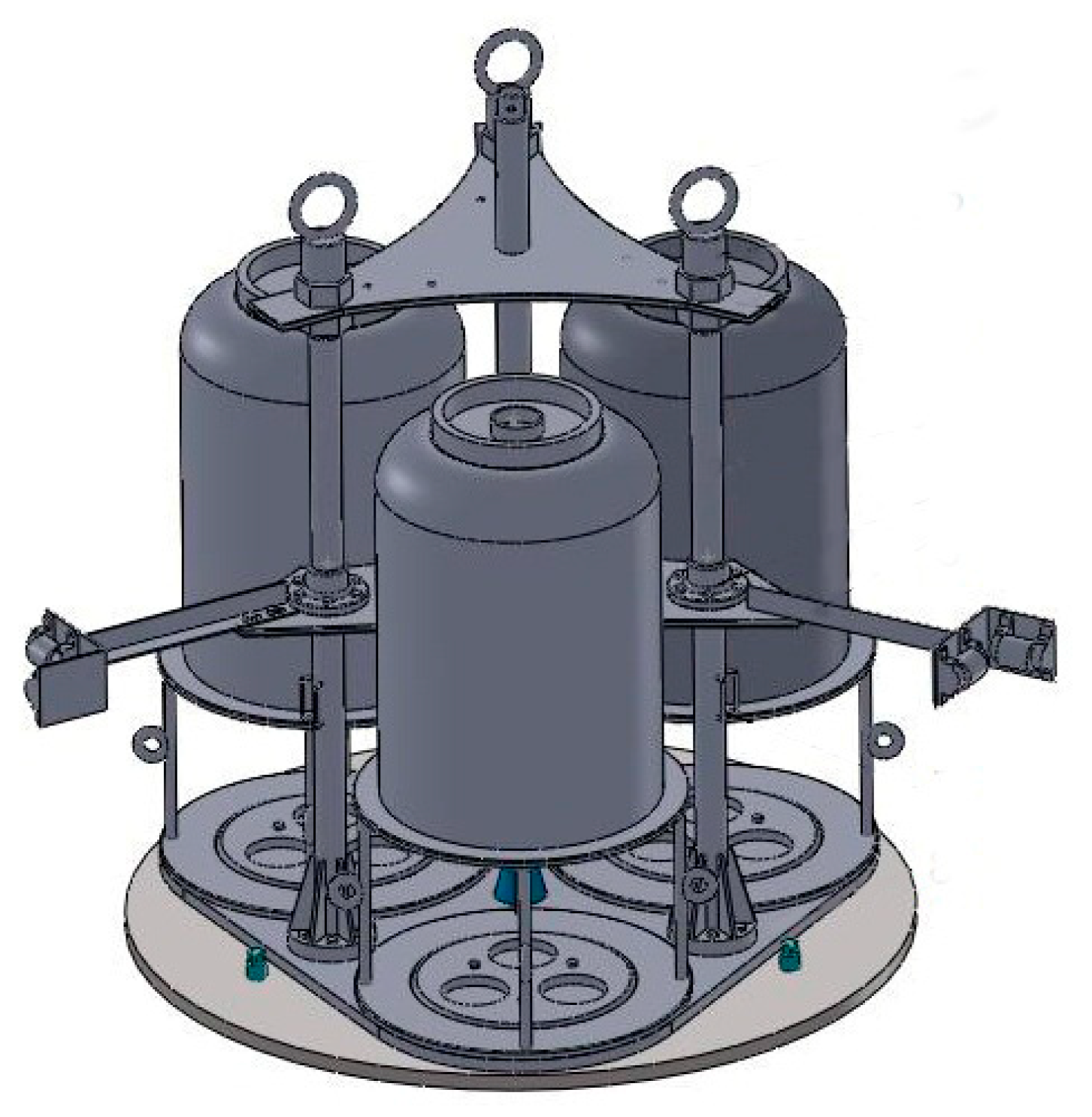
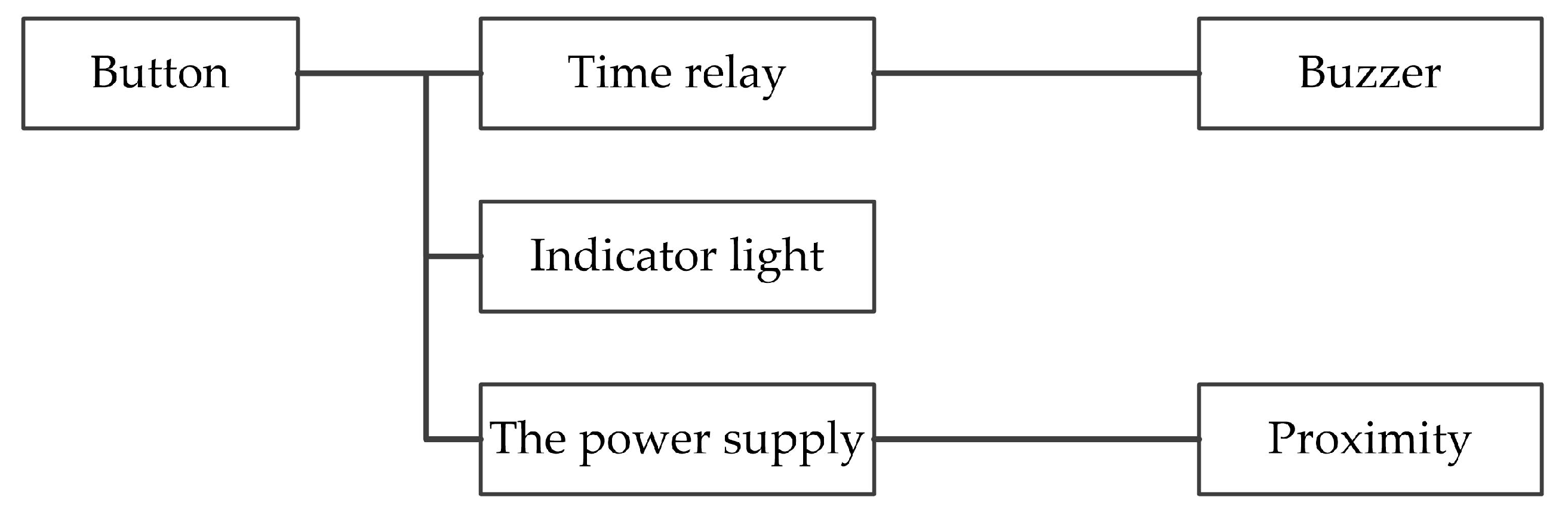
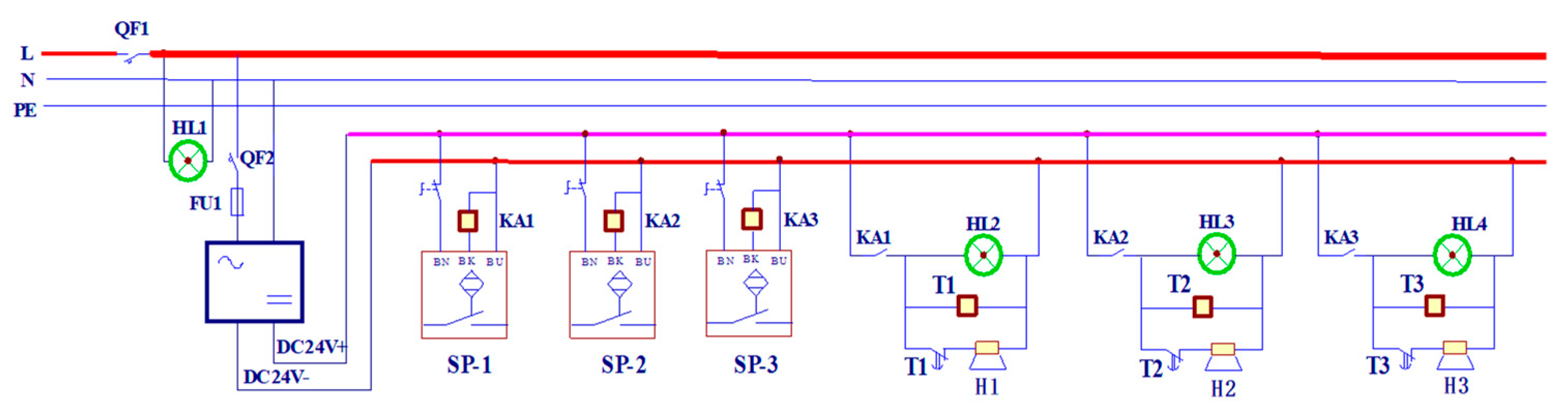
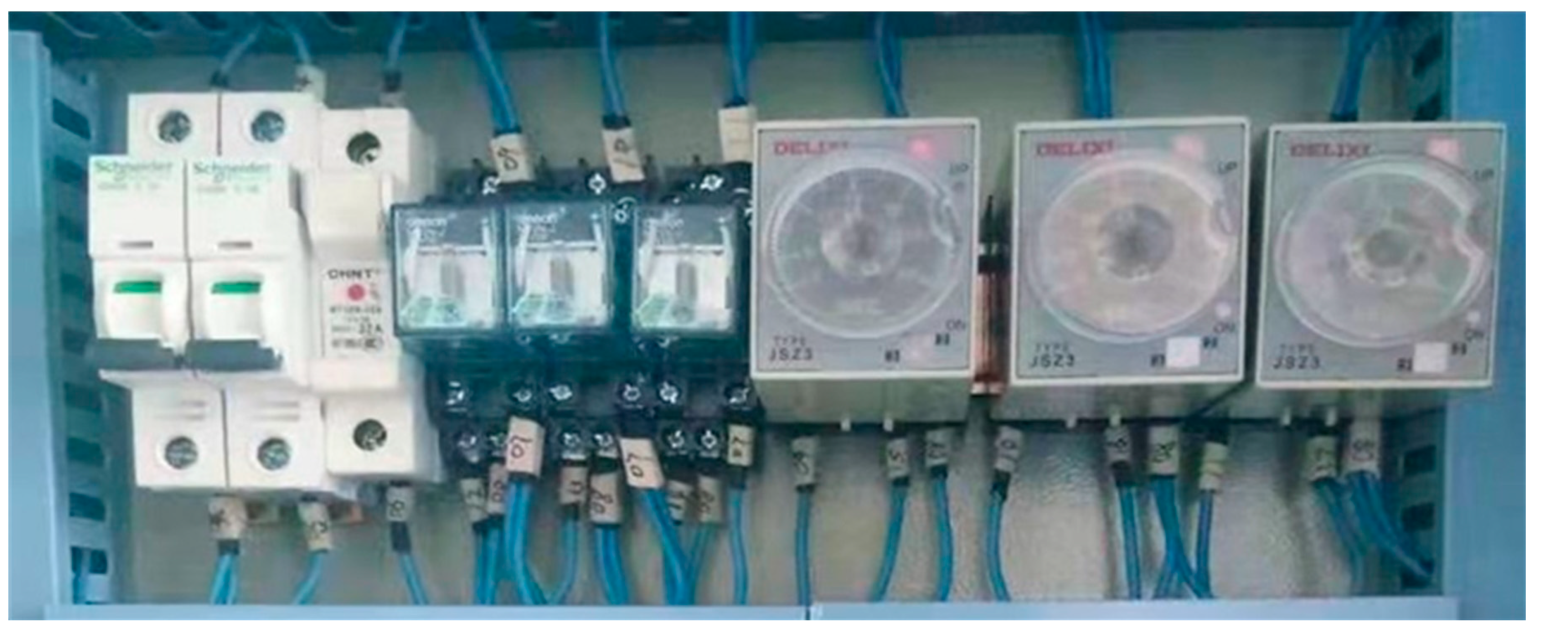
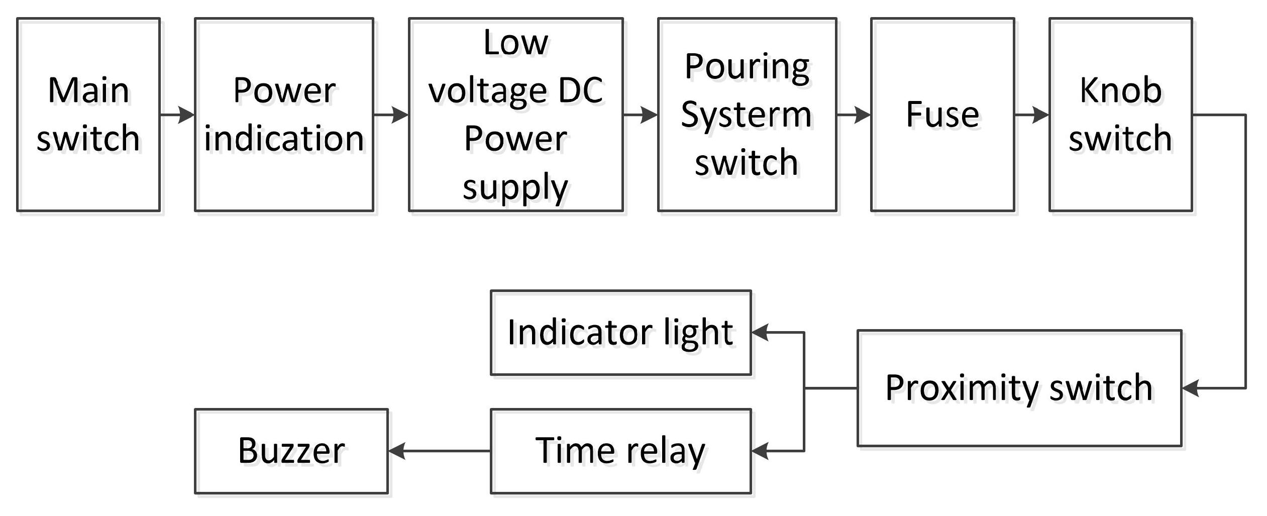
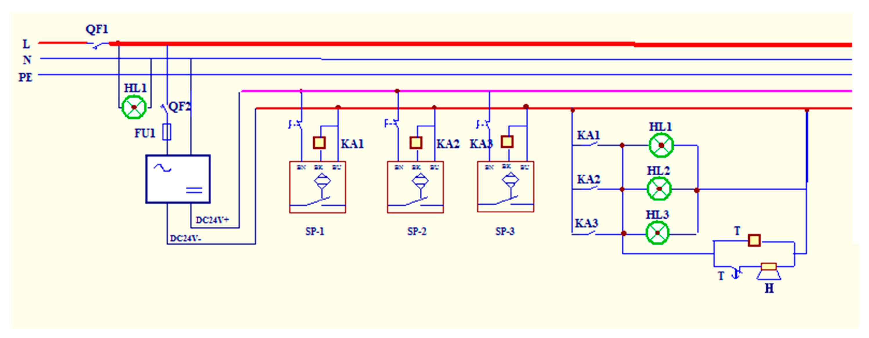
2. Model of Three-Engine Simultaneously Pouring Control Circuit System

In a three-engine simultaneous pouring system of a certain type of solid propellant rocket engine, as shown in Figure 1, a control system for detecting and alarming whether the propellant slurry poured is full of combustion chambers. The functions of the system are shown in Figure 2. It is also the key technology to realize the automatic control of the pouring process.
According to Figure 2 and Figure 3, it is easy to know that the system has many redundancies. Each engine pouring detection circuit is equipped with a proximity switch to detect whether the pouring is complete, and for the pouring result, not only an indicator light is set up, but also a buzzer alarm is equipped. The main electrical components of the pouring detection control system and their representative symbols have been marked, and they are low voltage DC power supply, fuse FU1, proximity switches SP-1, SP-2, SP-3, the power indicator light HL1, the main switch QF1, the pouring switch QF2, the pouring completion indicator lights HL1, HL2, HL3, the time relays T1, T2, T3, buzzers H1, H2, H3, and knob switches. A photo of the partial main physical, electrical circuit, and components of the control system is shown in Figure 4.
The control system can automatically detect whether the pouring is working or failing. The automatic control system takes the proximity switch as the core control element, which can realize the automatic sound and light alarm function and is more suitable for the remote control of the pouring process. Three proximity switches are equipped on the mechanical connectors called receiving trays, which are fixed on the pouring ports of three combustion chambers in the vacuum cylinder. There is a certain working distance between the proximity switch and the Propellant slurry overflowing from the pouring port to the receiving tray. The input signals of the control system come from proximity switches. When any of the proximity switches send a signal, its corresponding buzzer or indicator light alarms, indicating that the pouring work is complete, and when all three engines correspond to the buzzer or indicator alarm, it means that the pouring process of the entire three-engine system is complete.

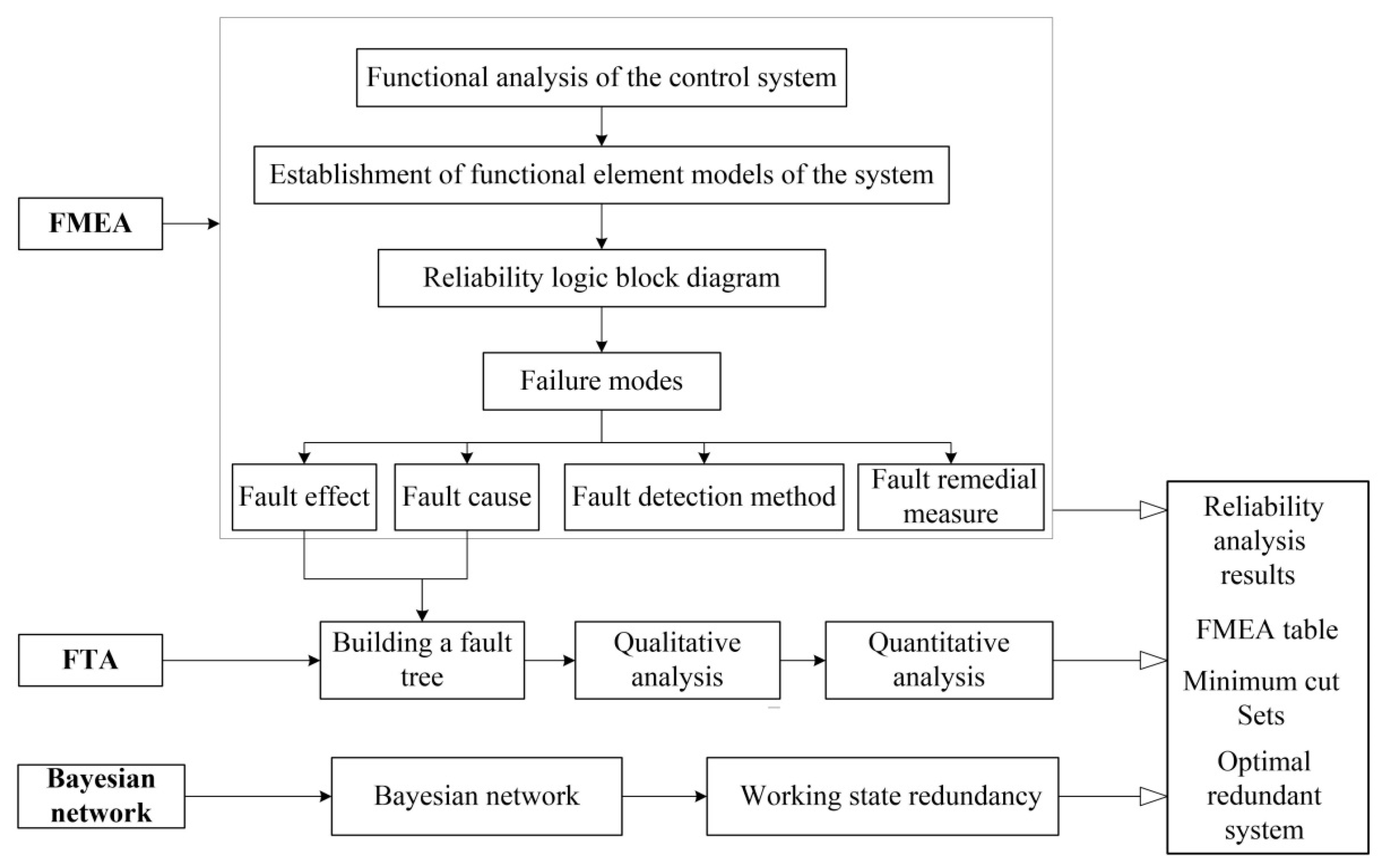
3. Reliability Analysis Flowchart of Three-Engine Pouring Control Circuit

The combination of FMEA and FTA can be effectively used in system design [7,21]. Based on this combined reliability analysis method, the Bayesian Networks method is used to further analyze and optimize the redundant circuits. The flowchart of the reliability analysis of the three-engine pouring control circuit is shown in Figure 5. Using the FMEA method, the system is divided into several different subsystems. Then, the possible failure modes, causes, and effects of each subsystem are analyzed one by one, and a detailed list is given to summarize and analyze the faults of the system or electronic components from the entire system. A fault tree is established in combination with the FMEA table, and then qualitative and quantitative analyses are performed based on the established FTA. Finally, the Bayesian network method is used for reliability evaluation and calculation.

4. FMEA Analysis of Three-Engine Pouring Control System

The FMEA is an important method to improve the reliability of systems or equipment [22]. As a planning method for precaution, the main purpose of FMEA is to discover and evaluate potential failures and consequences of the systems or equipment and to find ways to avoid or reduce the occurrence of faults or failures. In addition, this analysis is also the basis for fault tree analysis (FTA).

4.1. Establishment of Reliability Logic Block Diagram of Three-Engine Pouring Control System

As can be seen from Figure 3, the acousto-optic alarm control circuit system of the three-engine pouring process has automatic air circuit breakers, fuses, proximity switches, low-voltage DC power supplies, small relays, indicator lights, buzzers, and knob switches. According to the function, the system is graded into a series of subsystems, and the bottommost unit is a single electronic component. Therefore, the failure of arbitrary components will lead to the failure of the entire system to varying degrees. Before performing FMEA, according to their functions, the system reliability logic block diagram is established, as shown in Figure 6. Only one set of pouring control circuits is considered in this reliability logic block diagram, and the other two sets of pouring control circuits are ignored.

4.2. Failure Mode Effect Analysis
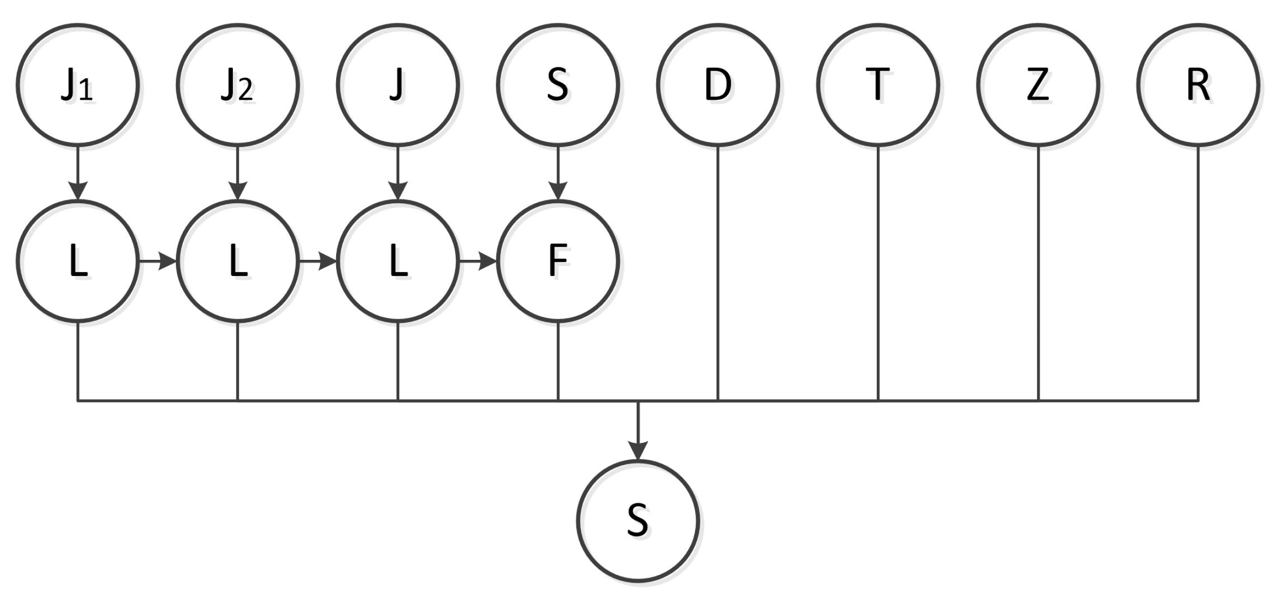
The FMEA method is used to analyze the components of the reliability logic block diagram in Figure 6. As a qualitative analysis result, the FMEA table of the single-engine pouring control circuit system is shown in Table 1.

5. FTA Analysis

The FTA method was first proposed in 1961 by American Bell Laboratories H.A. Watson and D.F. Hansl. Nowadays, the FTA is an important method for reliability analysis of complex systems and has been widely used in many fields.

5.1. Establishment of Reliability Logic Block Diagram of Three-Engine Pouring Control System

Based on the FMEA table of the three-engine pouring control circuit system, FT is constructed, as shown in Figure 7 and Figure 8.
In Figure 7 and Figure 8, Z, T, D, and R represent the main power switch failure, the pouring system switch, the low-voltage DC power supply, and the fuse, respectively. C represents the failure of the three subsystems of the control circuit, B represents the failure of one of the subsystems, J, X, L, S, and F are the failure of the proximity switch, the knob switch, the pouring completion indicator, the time relay, and the buzzer respectively. G represents the pouring completion failure, and g represents the buzzer indicating the failure. A represents the failure of the three-engine pouring system.

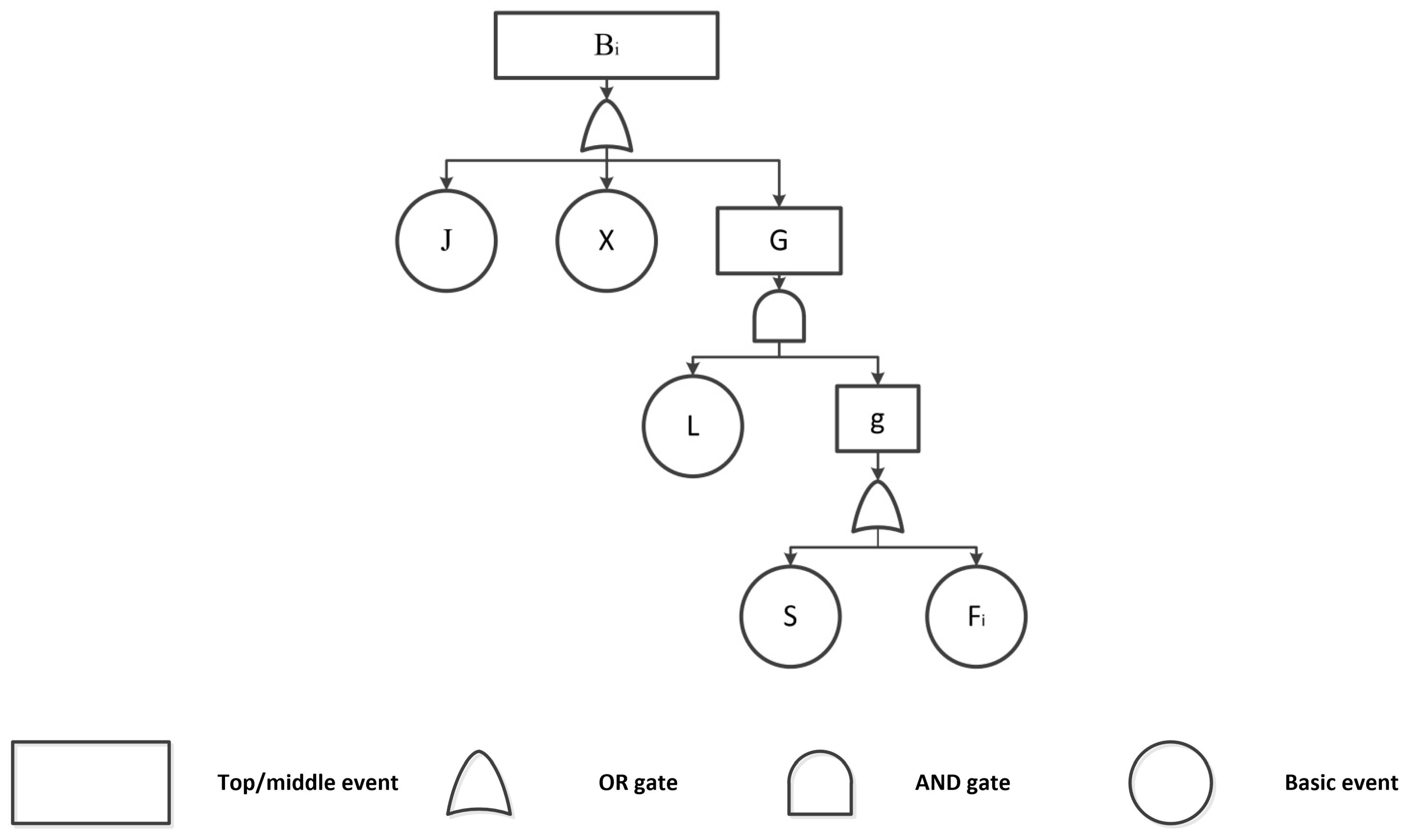
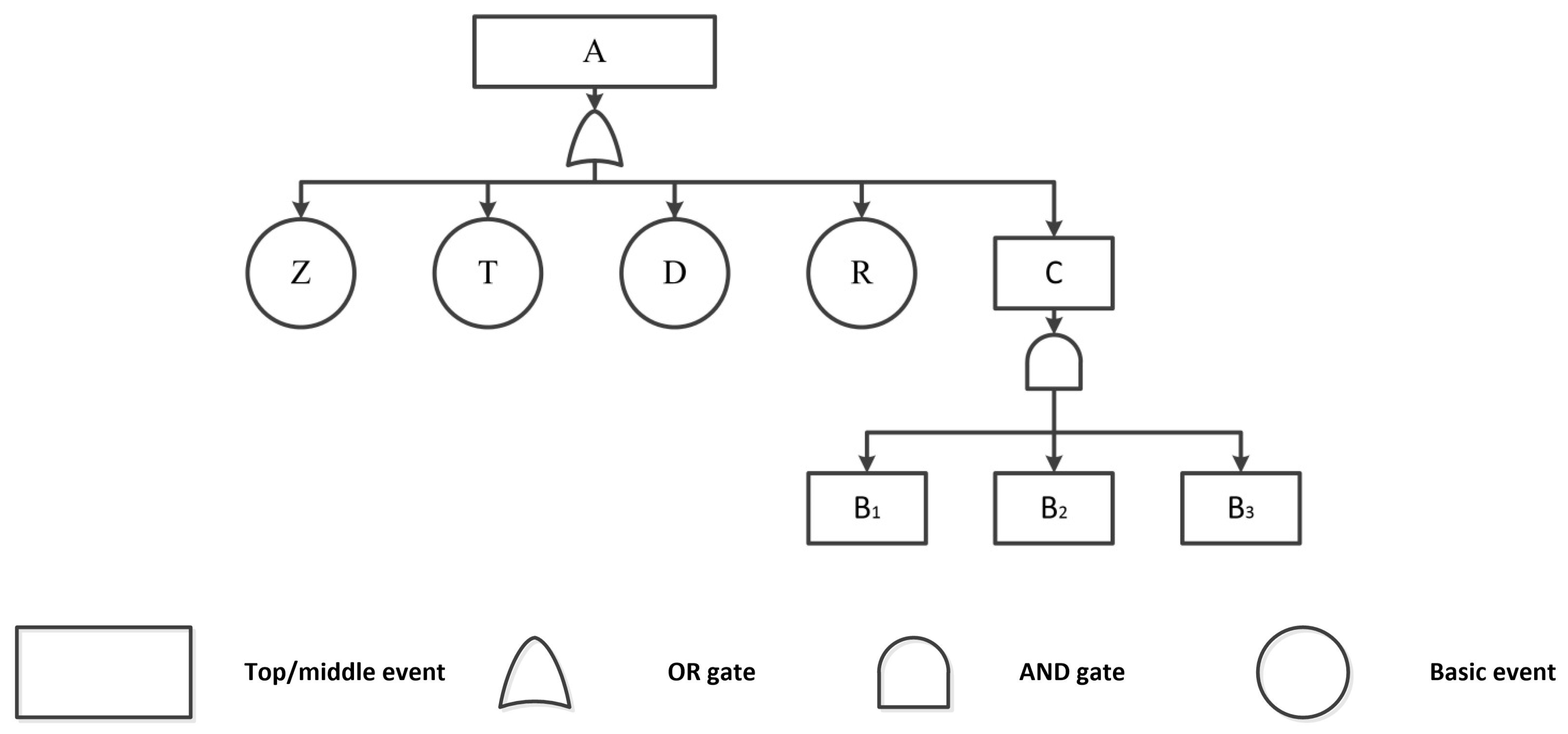
5.2. Fault Tree Analysis of Control Circuit System

The FTA method is used to study the various causes of system or equipment failure. Establish a logical relationship between failure causes, which are described by using the fault trees. The fault tree of the three-engine pouring control circuit system is established, and then the qualitative analysis and quantitative analysis are performed.

5.2.1. Qualitative Analysis

The fault tree is qualitatively analyzed using the Minimum Cut Set (MCS) method. The downlink method is adopted to find the MCS of the system. The MCS is a set of the minimum basic events that cause the top event to occur [23].
The MCSs for the fault tree of the three-engine pouring control circuit are: {Z}, {T}, {R}, {D}, {S, L}, {F, L}. The minimum cut sets are constructed by the corresponding components: {Z} represents the minimum cut set of component Z, {T} represents the minimum cut set of T, {R} represents the minimum cut set of T, {D} represents the minimum cut set of D, {S, L} represents the minimum cut set of S, L, {F, L} represents the minimum cut set of F, L.
Based on the results of the MCSs and occurrence and severity, the main switch, the rotary switch, and the proximity switch have significant effects on the failure of the three-engine pouring control circuit system. Therefore, the reliability of key components should be improved in the control circuit to minimize the occurrence of basic events and to reduce the minimum number of cut sets in the control system in practice.

5.2.2. Quantitative Analysis

The failure rate of each component is calculated based on the GJB/Z299D Electronic Equipment Reliability Prediction Manual, as shown in Table 2. The parameters involved are the basic failure rate λ b , the environmental coefficient π E , the contact form factor π C 1 , the contact load factor π L , the mass coefficient π Q , the rate of action factor π C Y C , the applied structural coefficient π A , the utilization factor π U , and the rated voltage coefficient π V .
(1)
The working failure rate of time relay
By consulting the Electronic Equipment Reliability Prediction Manual, the working failure rate of the time relay can be calculated as follows:
λ p = λ b π E π Q π C 1 π C Y C π A
where the basic failure rate is 0.094, the environmental coefficient is 1, the mass coefficient is 0.3, the number of contacts is 2, and the contact form factor is 1.7; the action rate coefficient and applied structure coefficient are taken as 0.1 and 10, respectively.
The calculated value of the working failure rate of the time relay is 0.096 × 10⁻⁶.
(2)
The working failure rate of the proximity switch
According to the relevant parameters of similar proximity switches, the failure rate of the proximity switches is taken as:
λ p J = 0.431 × 10 6
(3)
The working failure rate of the knob switch
The working failure rate of the switch can be calculated as:
λ p = ( λ b 1 + λ b 2 ) + π E π Q π L π C Y C
where the basic failure rate of the knob-type switch drive mechanism is 0.3, and the basic failure rate of the switch active contact is 0.14.
The calculated value of the working failure rate of the available knob switch is 0.736 × 10⁻⁶.
(4)
The working failure rate of the button switch
The basic failure rate of the drive mechanism in the button switch is 0.28, and the values of parameters are the same as those of the knob switch.
The calculated value of the working failure rate of the available button switch is 0.576 × 10⁻⁶.
(5)
The working failure rate of the indicator light
The working failure rate of the indicator light is calculated as follows:
λ p = λ b π E π U π V
based on the Electronic Equipment Reliability Prediction Manual, the basic failure rate of indicator light is 0.34; the environmental coefficient is 1.0; the utilization factor is 0.1; the rated voltage is 24 V, and the corresponding rated voltage coefficient is 7.6. The calculated value of the working failure rate of the indicator light is 0.258 × 10⁻⁶.
(6)
The working failure rate of the buzzer
According to the working failure rate of the electro-acoustic device, the failure rate of the buzzer is determined as
λ p f = 0.245 × 10 6
Note that the work failure rate of the buzzer can represent the work failure rate of the bell.
(7)
The working failure rate of low-voltage DC power supply
The operating failure rate of the low-voltage DC power supply is determined as
λ p y = 0.857 × 10 6
(8)
The working failure rate of the fuse
The working failure rate of the fuse is given by
λ p r = 0.150 × 10 6

5.3. Failure Probability of Main Components in Three-Engine Pouring Control Circuit System

As can be seen from Table 2, the electronic components with higher failure rates are the knob switch, low-voltage DC power supply, proximity switch, and the main switch. Based on the principle of system reliability, the reliability of a series-parallel system can be calculated as follows:
R B = ( 1 λ p t ) ( 1 λ p y ) ( 1 λ p x ) ( 1 λ p j ) { 1 λ p l [ 1 ( 1 λ p s ) ( 1 λ p f ) ] } = 0.999997
The probability of the top event for the three-engine pouring main control circuit system can be obtained, which is RB = 0.999997. The total probability of the three-engine pouring the entire control circuit system is no less than the probability of a series connection of three main control circuits Rsum, which is calculated as:
R s u m = R B 3 ( 1 λ P Z ) ( 1 λ P T ) ( 1 λ P D ) ( 1 λ P R ) = 0.999989
The mean time between failures is MTBF = 5 × 10⁴ h.

6. FTA Analysis

Bayesian Networks can solve interaction problems. For multi-state systems, a fault tree combined with the Bayesian Network method is used for system reliability analysis [21]. The reliability of the three-engine pouring control system is calculated on the premise that the subsystems are independent of each other. Aiming at the inter-effect on electrical components and redundancy design in the system, a polymorphic Bayesian Network is proposed and used to evaluate two dissimilar redundancy designs.
The Bayesian Networks of the three-engine pouring control system based on the fault tree established as shown in Figure 7 and Figure 8 is shown in Figure 9.
The conditional probabilities and prior probabilities for each node are calculated and listed in Table 3 and Table 4, respectively.
In this paper, the Bayesian toolbox BNT in MATLAB2016a software is used to calculate the edge probability distribution of the intermediate nodes of the Bayesian Networks [24]. By using the FullBNT-1.0.4 toolbox, the conditional probability and the posterior probability of each component can be calculated. The joint reference algorithm is applied to the model for bidirectional reasoning [4,12]. Using the forward reasoning of the network, the conditional probability of the top event occurring when each bottom event in the original fault tree model occurs alone is calculated, as shown in Table 5. Using backward reasoning, the posterior probability value of each bottom event is calculated, as shown in Table 6.
In the three-engine pouring control system, a four-way pouring delivery device is used to complete the pouring process. Therefore, the pouring completion time of the three engines is almost the same. However, the cost of pouring is very high in order to ensure that there are no accidents in the control system in the pouring process. Thus, the pouring process of three engines is separately monitored. This leads to the redundancy of the three-engine pouring control system.
According to the alarm function and the number of subsystems, the redundancy of the three-engine pouring control system can be divided into four states. Provided that one subsystem exists, the alarm state is set to I; two subsystems exist, the alarm state is set to II; three subsystems exist, the alarm state is set to III. If no subsystem exists, the alarm state is set to 0. Therefore, there are many condition states in this system. Buzzer alarm includes a time relay and buzzer and can be considered as a whole one. One of the Bayesian Networks is shown in Figure 10, and the corresponding circuit is shown in Figure 11. The reliability results of all states are shown in Table 7.
For redundancy allocation in failure interaction, an improved analytic hierarchy process (MAHP) is proposed in reference [25]. Based on this method, the system is decomposed into blocks and reduced blocks, and then the most suitable redundancy allocation components are given. According to the calculation results in Table 7, the system is required to be highly reliability. However, more buzzers will make louder noises. The alarm circuit is taken, including three lights in each subsystem. The circuit diagram of the improved three-engine pouring control system is shown in Figure 11. The corresponding Bayesian Network is shown in Figure 10.

7. Discussion

The proposed reliability analysis method combining FMEA, FTA, and Bayes Networks method is used in the reliability analysis of complex equipment control systems to avoid sufficient consideration of problems in the reliability analysis of the system, but the quantification of the analysis results is not accurate enough. The FTA analysis is carried out based on completing the FMEA analysis of the three-engine simultaneous pouring control system. In this way, the bottom-up FMEA analysis is combined with the top-down FTA analysis method, making the model established by the FTA analysis method more targeted, simplifying the analysis process and providing reliable results. The FMEA method is used to analyze the components of the three casting control systems. When analyzing and identifying the fault mode, the influence of the components is identified. This helps find the cause of the fault and has guiding significance for the design and maintenance. The system fault tree is established, and the weakest part of the system can be determined according to the obtained minimum cut set. The high-reliability equipment components are used to reduce the occurrence of basic events or redundancy designs and then to reduce the number of minimum cut sets. The mean time between failure (MTBF) of the control system is obtained through the quantitative analysis of the minimum cut set, based on which the reliability of the three-casting control system is judged and improved. Because of the various states of the system, the Bayes network is selected to use a finite set to record the probability of the system in each state, model the uncertainty of the system according to the known data, and then predict the future state of the system. The results show that adding some guaranteed parts will greatly improve the reliability of the system. Considering the importance of solid rocket engine reliability requirements, it is particularly important to add redundancy to the system design. The weight is calculated by the MAHP analysis method, and the necessary redundant components are selected to optimize the three-engine simultaneous pouring control system and improve the reliability of the three-engine simultaneous pouring control system.

8. Conclusions

In this paper, the FMEA, FTA, and Bayesian Network methods are combined to evaluate the three-engine pouring control system of a solid propellant rocket engine. In order to prolong the service life of the system, the failure mode effect analysis of the solid propellant rocket engine three-engine control system was carried out, and the FMEA analysis results were further quantified using the forward and backward reasoning of the Bayesian Network. In order to improve system reliability, an optimized dissimilar redundancy design is proposed. Human-machine relationships and refurbishment cycles were taken into account, and the design was divided into redundant shared design and non-redundant shared design. The two dissimilar redundancy designs were analyzed using Bayesian Networks based on FTA. The results show that the buzzer is the component that has the greatest effect on the system. The buzzer is used as a redundant component-sharing scheme to improve the reliability of the system when using the least components. The application of the proposed method has been proved by numerical examples. This model can help engineers carry out inspection and maintenance plans, which can improve the performance of economic and safety control systems. The design of the three-engine simultaneous pouring control system can meet the production demand, but the reliability test of the equipment still needs to be carried out in the actual production. The ideas and methods proposed by this research work can be applied to more complex and multi-status electromechanical products, and its application will show more advantageous effects.

Author Contributions

Conceptualization, Z.C. and M.Z.; Methodology, Z.C. and M.Z.; Software, M.Z. and J.L.; Validation, Z.C. and M.Z.; Formal analysis, Z.C., M.Z. and J.W.; Investigation, Z.C. and M.Z.; Resources, M.Z.; Data curation, Z.C. and M.Z.; Writing—original draft, Z.C. and M.Z.; Writing—review & editing, Z.C. and M.Z. All authors have read and agreed to the published version of the manuscript.

Funding

This work is supported by The National Natural Science Foundation of China, No. 51965048.

Institutional Review Board Statement

Not applicable.

Informed Consent Statement

Not applicable.

Data Availability Statement

No new data were created or analyzed in this study. Data sharing is not applicable to this article.

Acknowledgments

Thanks to Jianjun Li and Inner Mongolia Hongxia Chemical Plant for providing support and help to the research of this paper.

Conflicts of Interest

The authors declare that they have no conflicts of interest to report regarding the present study.

References

  1. Xu, L.; Hou, S.Q. Development of solid rocket engine integrated pouring real-time monitoring system. Manuf. Autom. 2011, 42–46. [Google Scholar] [CrossRef]
  2. Meng, D.B.; Yang, S.Y.; Lin, T.; Wang, J.P.; Yang, H.F.; Lv, Z.Y. RBMDO using gaussian mixture model-based second-order mean-value saddlepoint approximation. CMES Comput. Model. Eng. Sci. 2022, 132, 553–568. [Google Scholar] [CrossRef]
  3. Meng, D.B.; Yang, S.Y.; Heg, C.; Wang, H.T.; Lv, Z.Y.; Guo, Y.P.; Nie, P. Multidisciplinary design optimization of engineering systems under uncertainty: A review. Int. J. Struct. Integr. 2022, 13, 565–593. [Google Scholar] [CrossRef]
  4. Meng, D.B.; Yang, S.Y.; de Jesus, M.P.A.; Zhu, S.P. A novel Kriging-model-assisted reliability-based multidisciplinary design optimization strategy and its application in the offshore wind turbine tower. Renew. Energy 2023, 203, 407–420. [Google Scholar] [CrossRef]
  5. Meng, D.B.; Yang, S.Q.; Zang, Y.; Zhu, S.P. Structural reliability analysis and uncertainties-based collaborative design and optimization of turbine blades using surrogate model. Fatigue Fract. Eng. Mater. Struct. 2019, 42, 1219–1227. [Google Scholar] [CrossRef]
  6. Zhi, P.P.; Wang, Z.L.; Chen, B.Z.; Sheng, Z.Q. Time-variant reliability-based multi-objective fuzzy design optimization for anti-roll torsion bar of EMU. CMES Comput. Model. Eng. Sci. 2022, 131, 1001–1022. [Google Scholar] [CrossRef]
  7. Su, H.; Wang, W. Analysis on reliability and security of ZPW-2000A track circuit system based on FMEDA and FTA. Sens. Transducers 2013, 25, 161. [Google Scholar]
  8. Tian, Z.R.; Zhi, P.P.; Guan, Y.; He, X.H. An active learning Kriging-based multipoint sampling strategy for structural reliability analysis. Qual. Reliab. Eng. Int. 2023, 3403. [Google Scholar] [CrossRef]
  9. Ding, R.; Liu, Z.; Xu, J.; Meng, F.; Sui, Y.; Men, X. A novel approach for reliability assessment of residual heat removal system for HPR1000 based on failure mode and effect analysis, fault tree analysis, and fuzzy Bayesian network methods. Reliab. Eng. Syst. Saf. 2021, 216, 107911. [Google Scholar] [CrossRef]
  10. Liu, H.C.; Liu, L.; Liu, N. Risk evaluation approaches in failure mode and effects analysis: A literature review. Expert Syst. Appl. 2013, 40, 828–838. [Google Scholar] [CrossRef]
  11. Wang, Y.M.; Chin, K.S.; Poon, G.K.K.; Yang, J.B. Risk evaluation in failure mode and effects analysis using fuzzy weighted geometric mean. Expert Syst. Appl. 2009, 36, 1195–1207. [Google Scholar] [CrossRef]
  12. Shu, M.H.; Cheng, C.H.; Chang, J.R. Using intuitionistic fuzzy sets for fault-tree analysis on printed circuit board assembly. Microelectron. Reliab. 2006, 46, 2139–2148. [Google Scholar] [CrossRef]
  13. Mzougui, I.; Elfelsoufi, Z. Improvement of Failure Mode, Effects, and Criticality Analysis by Using Fault Tree Analysis and Analytical Hierarchy Process. J. Fail. Anal. Preven. 2009, 19, 942–949. [Google Scholar] [CrossRef]
  14. Nazlı Gülüm, M.; Serkan, A. Risk analysis for occupational safety and health in the textile industry: Integration of FMEA, FTA, and BIFPET methods. Int. J. Ind. Ergon. 2019, 72, 222–240. [Google Scholar]
  15. Deshpande, A. Fuzzy fault tree analysis: Revisited. Int. J. Syst. Assur. Eng. Manag. 2011, 2, 3–13. [Google Scholar] [CrossRef]
  16. Kim, H.Z. Optimal reliability design of a system with k-out-of-n subsystems considering redundancy strategies. Reliab. Eng. Syst. Saf. 2017, 167, 572–582. [Google Scholar] [CrossRef]
  17. Wang, S.; Cui, X.; Shi, J. Modeling of reliability and performance assessment of a dissimilar redundancy actuation system with failure monitoring. Chin. J. Aeronaut. 2016, 29, 799–813. [Google Scholar] [CrossRef]
  18. Wang, Z.L.; Zhao, D.Y.; Guan, Y. Flexible-constrained time-variant hybrid reliability-based design optimization. Struct. Multidiscip. Optim. 2023, 66, 89. [Google Scholar] [CrossRef]
  19. Tian, Z.R.; Zhi, P.P.; Guan, Y.; Feng, J.B.; Zhao, Y.D. An effective single loop Kriging surrogate method combing sequential stratified sampling for structural time-dependent reliability analysis. Structures 2023, 53, 1215–1224. [Google Scholar] [CrossRef]
  20. Xie, J.X.; Tian, Z.R.; Zhi, P.P.; Zhao, Y.D. Reliability analysis method of coupling optimal importance sampling density and multi-fidelity Kriging model. Eksploat. Niezawodn.—Maint. Reliab. 2023, 25, 161893. [Google Scholar] [CrossRef]
  21. Peeters, J.F.W.; Basten, R.J.I.; Tinga, T. Improving failure analysis efficiency by combining FTA and FMEA in a recursive manner. Reliab. Eng. Syst. Saf. 2018, 172, 36–44. [Google Scholar] [CrossRef]
  22. Xiao, N.C.; Li, Y.f.; Huang, H.Z. Research on Reliability Analysis Method of Satellite Solar Wing Expansion Mechanism. J. Astronaut. 2009, 30, 1704–1710. [Google Scholar]
  23. Sánchez-Herguedas, A.; Mena-Nieto, A.; Rodrigo-Muñoz, F. A new analytical method to optimise the preventive maintenance interval by using a semi-Markov process and z-transform with an application to marine diesel engines. Reliab. Eng. Syst. Saf. 2021, 207, 107394. [Google Scholar] [CrossRef]
  24. Mi, J.; Li, Y.F.; Yang, Y.J. Reliability assessment of complex electromechanical systems under epistemic uncertainty. Reliab. Eng. Syst. Saf. 2016, 152, 1–15. [Google Scholar] [CrossRef]
  25. Wang, J.; Li, M. Redundancy Allocation for Reliability Design of Engineering Systems with Failure Interactions. J. Mech. Des. 2015, 137, 031403. [Google Scholar] [CrossRef]
Figure 1. Three-engine simultaneously pouring system of a solid propellant rocket engine.
Applsci 13 11546 g001
Figure 2. Schematic diagram of three-engine pouring control circuit system.
Applsci 13 11546 g002
Figure 3. The circuit diagram of the three-engine simultaneously pouring control system.
Applsci 13 11546 g003
Figure 4. Partial physical circuits of the three-engine simultaneous pouring control system.
Applsci 13 11546 g004
Figure 5. Reliability analysis flowchart of three-engine pouring control circuit.
Applsci 13 11546 g005
Figure 6. Reliability logic block diagram of the main part of the control circuit.
Applsci 13 11546 g006
Figure 7. The fault tree model of the subsystem.
Applsci 13 11546 g007
Figure 8. The fault tree model of the three-engine pouring control system.
Applsci 13 11546 g008
Figure 9. Polymorphic Bayesian Networks of three-engine pouring control system.
Applsci 13 11546 g009
Figure 10. Bayesian Network with I state and only one buzzer.
Applsci 13 11546 g010
Figure 11. The improved circuit diagram of the three-engine pouring control system.
Applsci 13 11546 g011
Table 1. FMEA table of the main part circuit for the three-engine pouring control system.
NameFailure ModeFailure ConsequenceFault Detection MethodRemedial Measure
Main switchPoor contact with the contactsAlarm failureThe power indicator is offTimely replacement
Short circuit between contactsAlarm failureThe power indicator is off
Time relaycontact adhesionSystem reliability reducedDebug before use,
If the LED indicator is on, but the buzzer does not ring
Timely replacement
Large contact resistance or intermittent
Contact disconnection failure
Broken wire of the coil
Sealing failure
Indicator lightVoltage breakdownAlarm effect decreased
or alarm failure
Pressing the main switch indicator does not lightTimely replacement
Knob switchPoor contact with the contactsAlarm failureVoltage measurementTimely replacement
FuseLoosening of supporting partsAlarm failureVoltage measurementTimely replacement
Low-voltage DC powerOpen circuitAlarm failureLow-voltage DC power light does not shineTimely replacement
Proximity switchopen circuitAlarm failureVoltage measurementTimely replacement
Short circuit
Electrical parameter degradation
contact adhesion
BuzzerVoltage breakdownSystem reliability reduced
Alarm effect decreased
or alarm failure
Patrol methodTimely replacement
Table 2. The failure rate of each component of the three-engine pouring control circuit system.
NameFailure Rate
(10−6)
NameFailure Rate
(10−6)
Time relay0.096proximity switch0.431
Knob Switch0.736Main Switch0.576
Indicator light0.258buzzer0.245
Low-voltage DC power supply0.857Fuse0.150
Table 3. g point CPT (Conditional Probability Table).
SFP(g = 1|S,F)
000
010
100
111
Table 4. A point CPT (Conditional Probability Table).
B1B2B3P(A = 1|B1,B2,B3)
0000
1002
0102
1102
1111
Table 5. Conditional probability table.
Event CodeFailure ProbabilityEvent CodeFailure ProbabilityEvent CodeFailure Probability
D1.0000Yi1.0000Ti1.0000
Z1.0000Xi1.0000Li4.117 × 10−6
R1.0000Ji1.0000Si3.258 × 10−6
Fi3.258 × 10−6
Table 6. Posterior probability values.
Event CodeFailure ProbabilityEvent CodeFailure ProbabilityEvent CodeFailure Probability
D0.129Yi0.129Ti0.288
Z0.288Xi0.368Li0.129
R0.075Ji0.216Si0.048
Fi0.123
Table 7. Probability distribution of three states.
0IIIIII
Redundancy is 00.2 × 10⁻⁵ 0.3 × 10−50.6 × 10−50.999989
Redundancy is 81.1 × 10⁻⁵ 3.5× 10⁻⁵ 4 × 10−50.999914
Disclaimer/Publisher’s Note: The statements, opinions and data contained in all publications are solely those of the individual author(s) and contributor(s) and not of MDPI and/or the editor(s). MDPI and/or the editor(s) disclaim responsibility for any injury to people or property resulting from any ideas, methods, instructions or products referred to in the content.

