
Braking Intention Identification Strategy of Electric Loader Based on Fuzzy Control

Abstract
:Featured Application
Abstract
1. Introduction
2. Analysis of Typical Working Conditions of Electric Loader
2.1. Working Mode
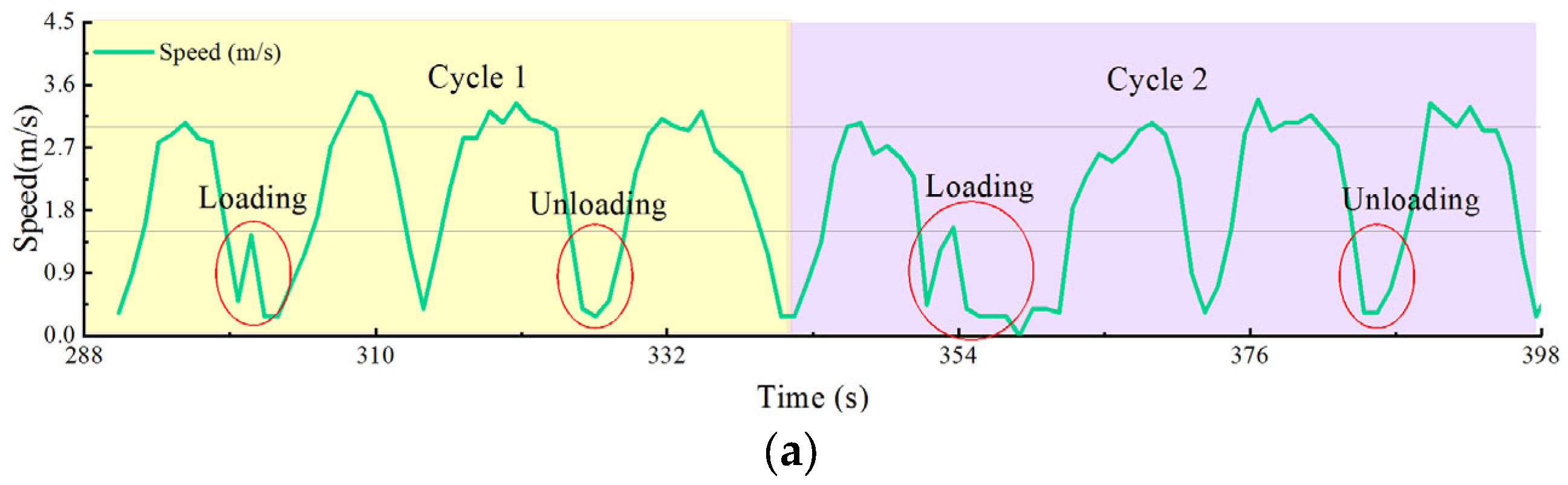
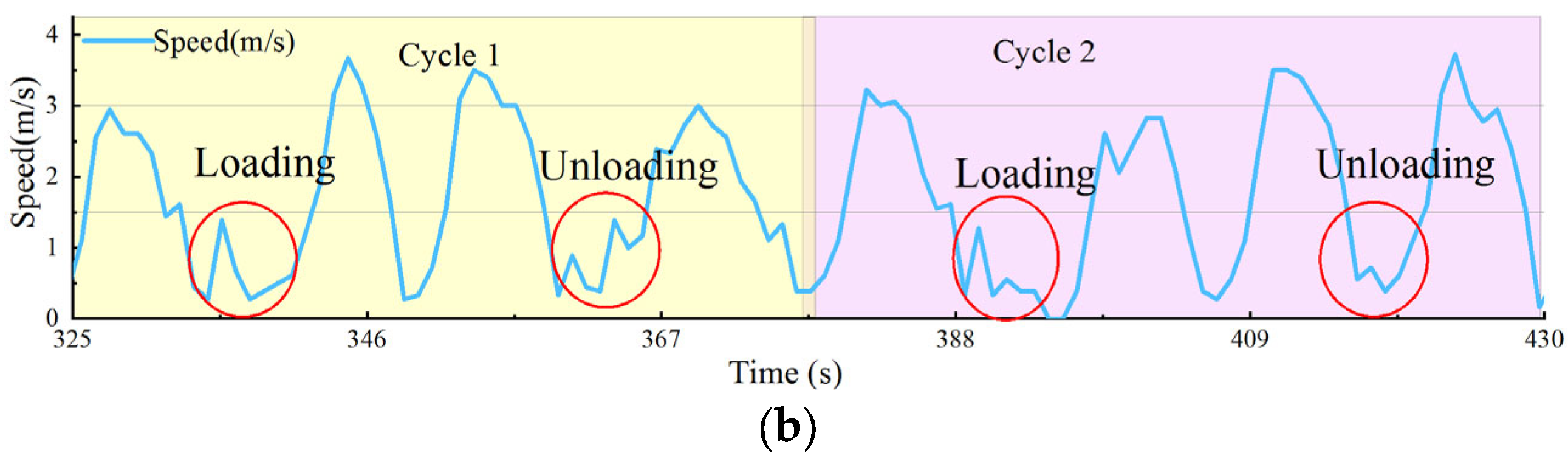
2.2. The Test of Working Conditions under “V” and “T” Types
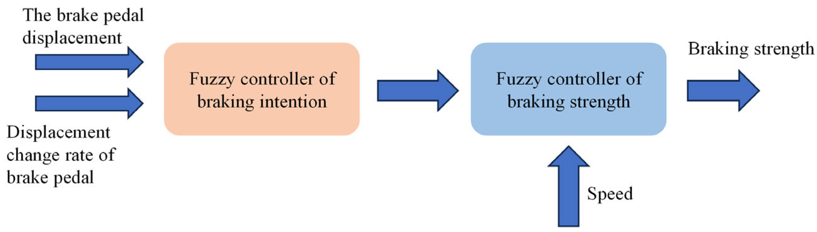
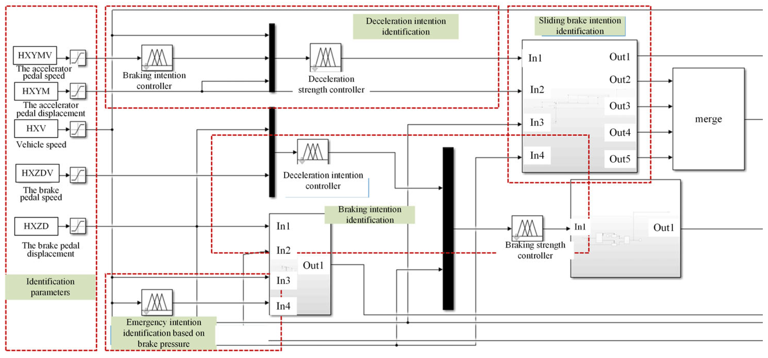
3. Fuzzy Controller Design
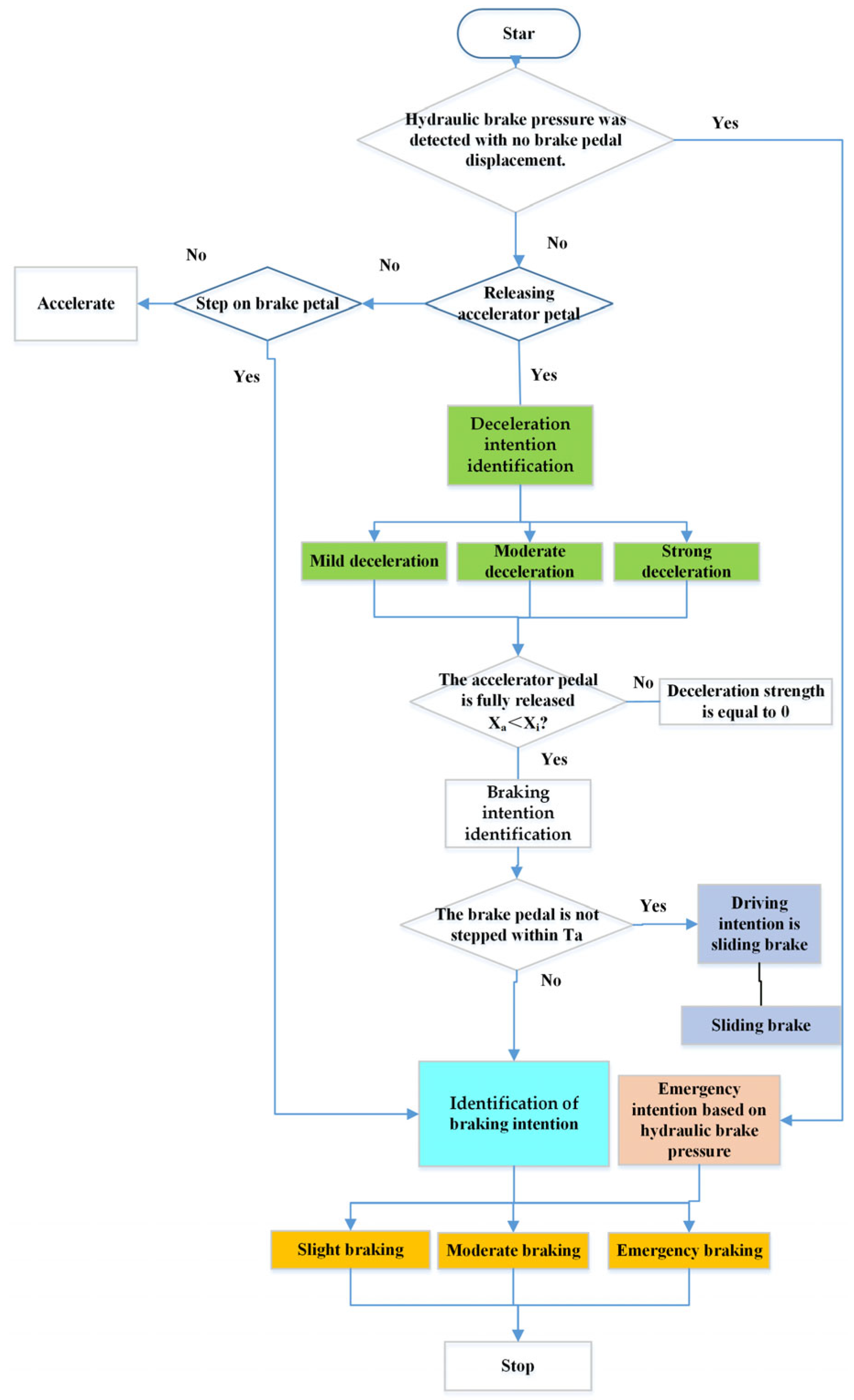
3.1. Braking Conditions Analysis
- (1)
- Sliding brake. The driver releases the accelerator pedal completely and does not step on the brake pedal. The vehicle speed is only affected by the friction force of ground and air, which is named sliding brake condition.
- (2)
- Mild braking. The driver releases the accelerator pedal completely and steps on the brake pedal gently, the braking strength demand is small. The purpose is mainly to adjust speed, avoid obstacles, or brake under a small speed.
- (3)
- Moderate braking. The driver releases the accelerator pedal completely and steps on brake pedal with a moderate speed, the brake pedal displacement continues to increase or maintain at a medium value. At this time, the braking strength increases, and the braking distance is shorter.
- (4)
- Emergency braking: When there is an emergency situation during driving, it is hoped that electric loader can brake immediately, so the driver steps on the brake pedal with the fastest speed, the brake pedal displacement reaches the maximum.
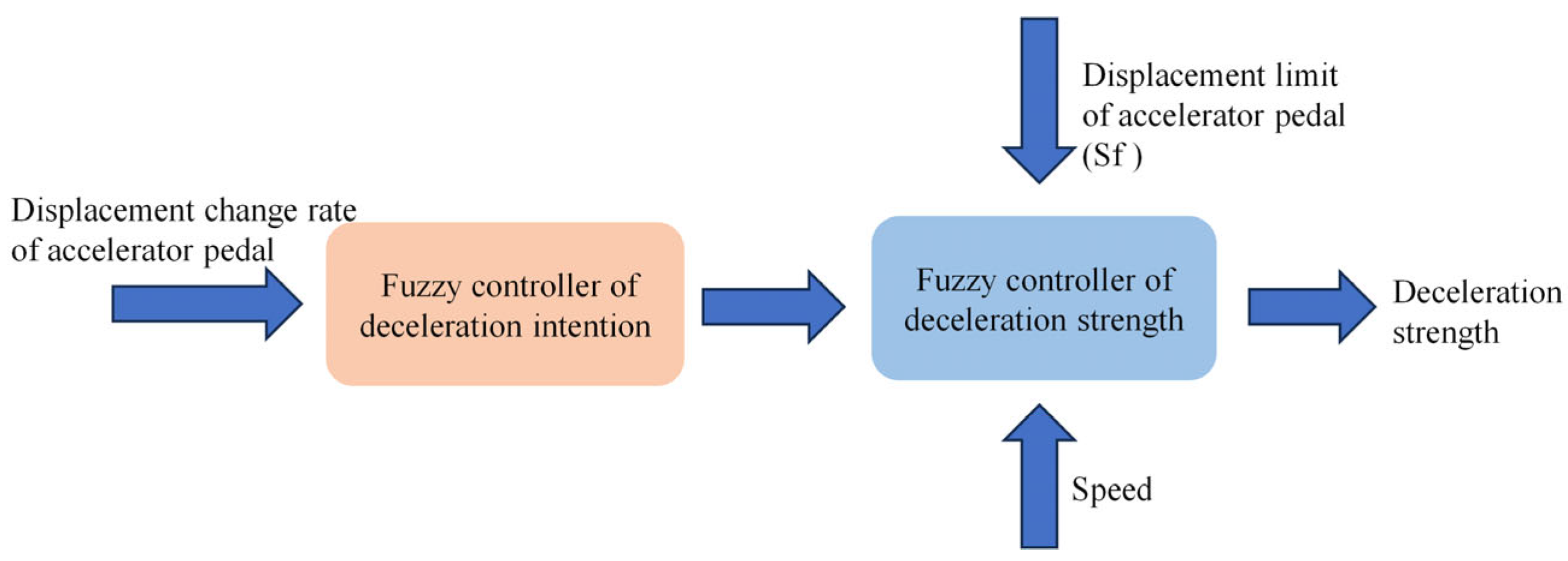
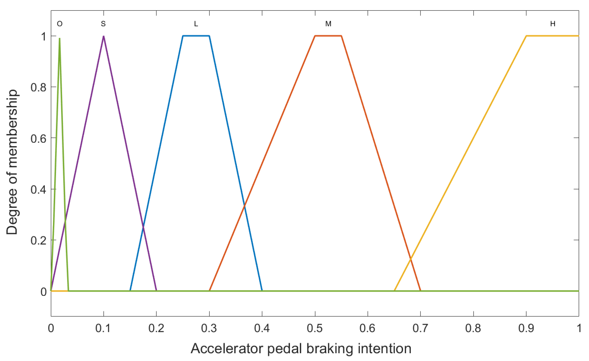
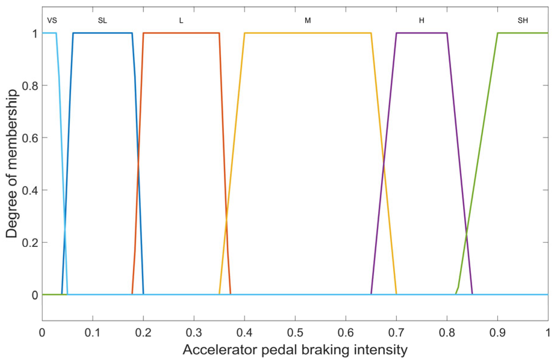
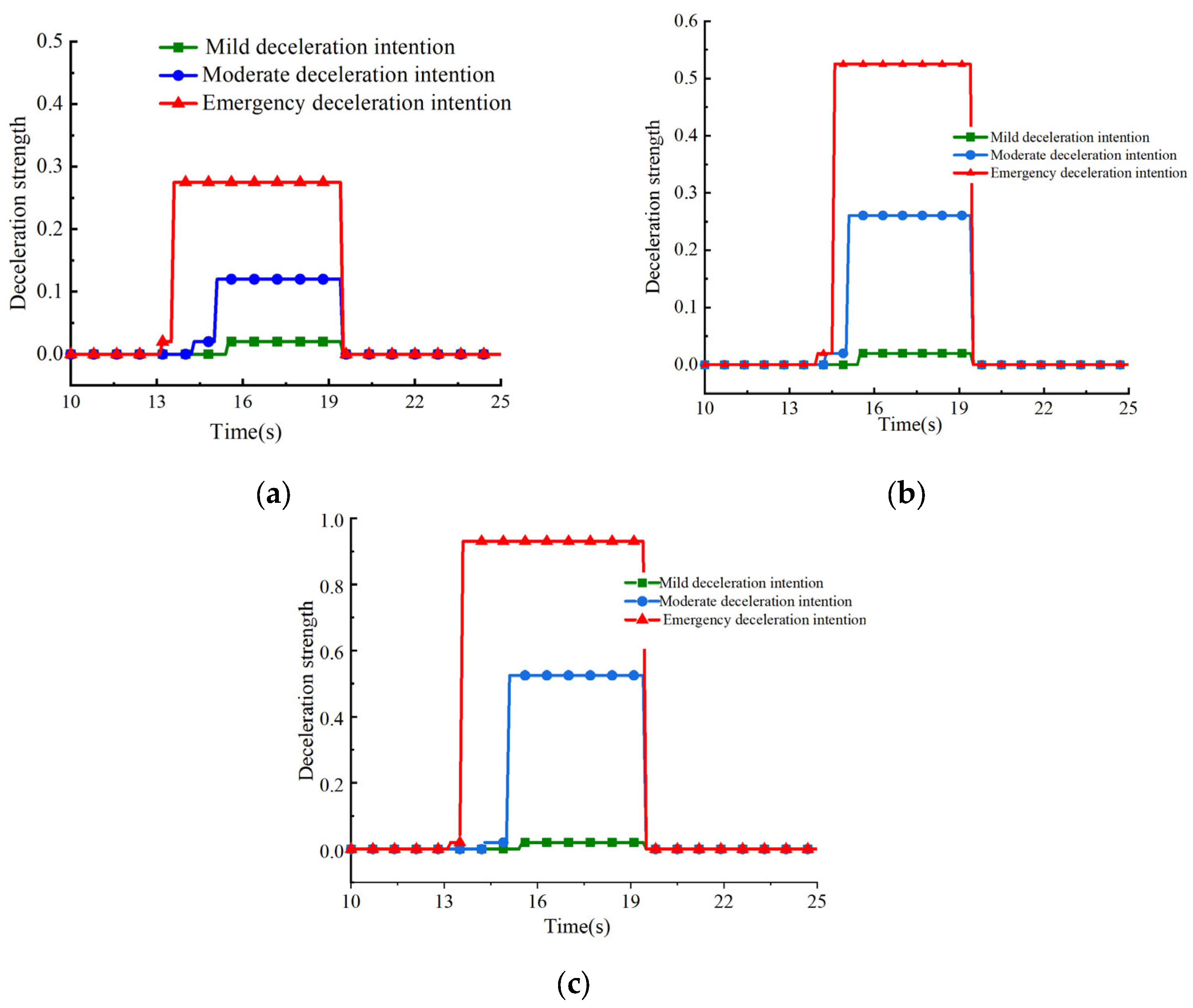
3.2. Deceleration Intention Identification Based on Accelerator Pedal
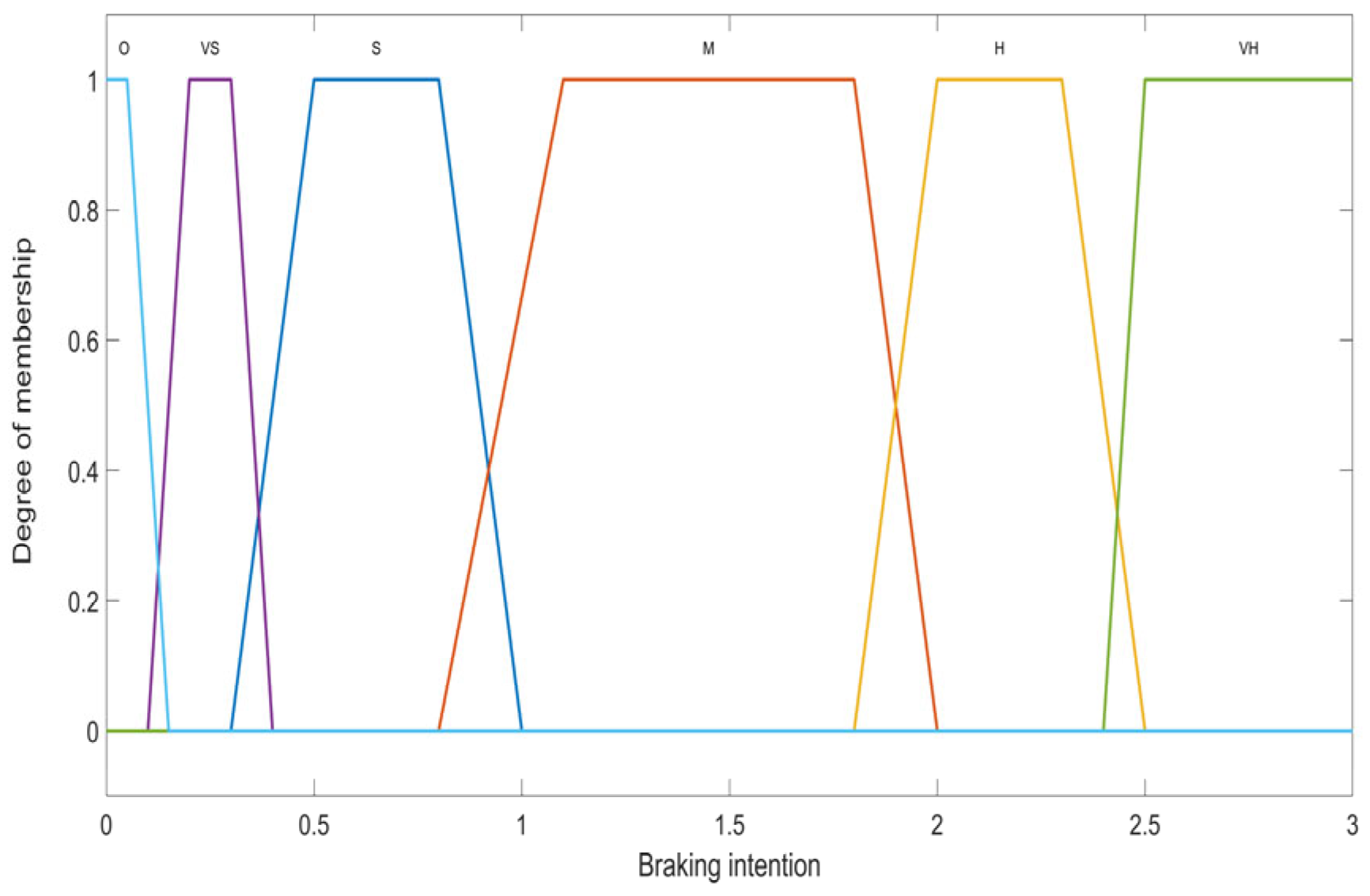
3.3. Braking Intention Identification Based on Brake Pedal
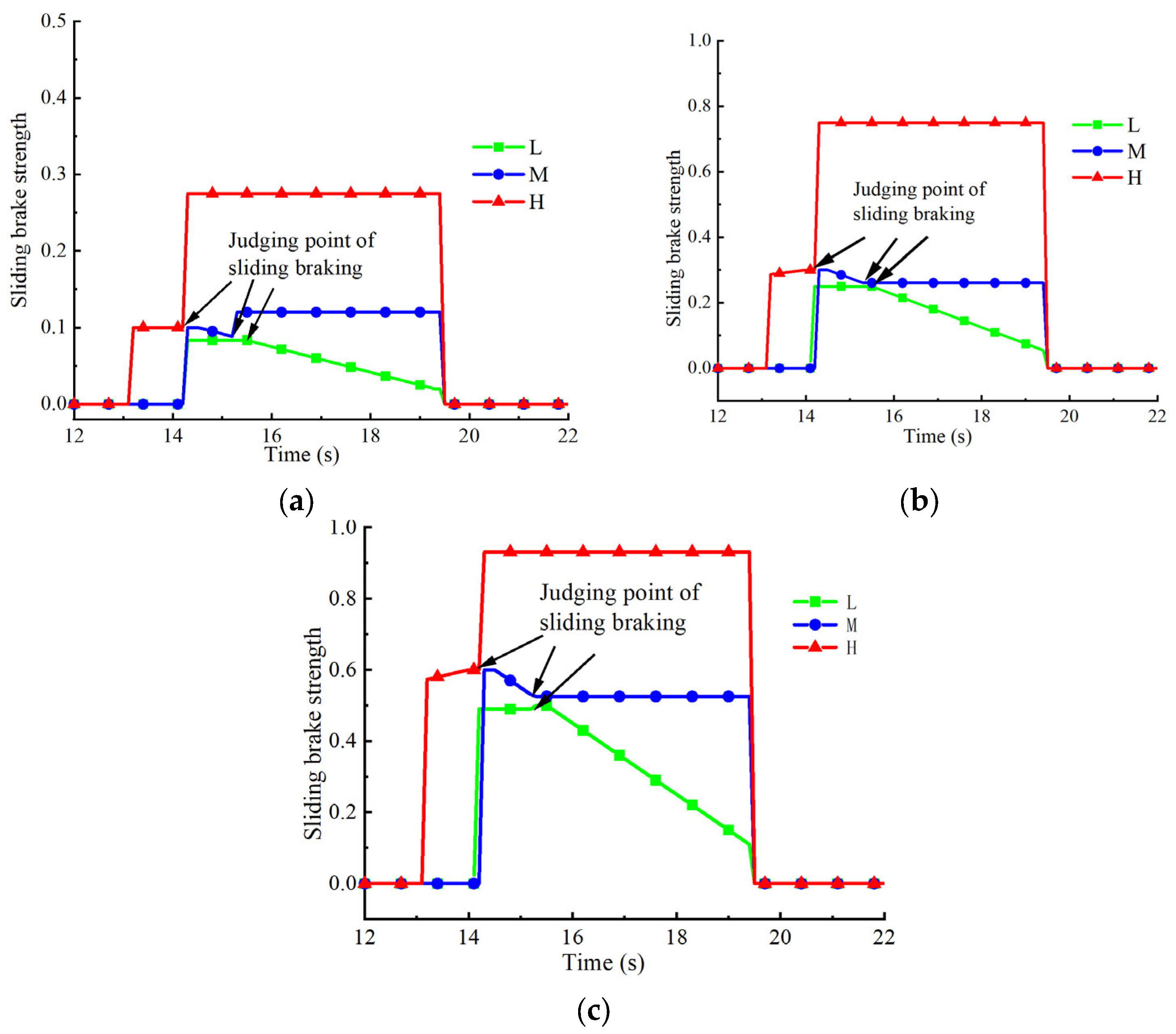
3.4. Sliding Brake Intention Identification
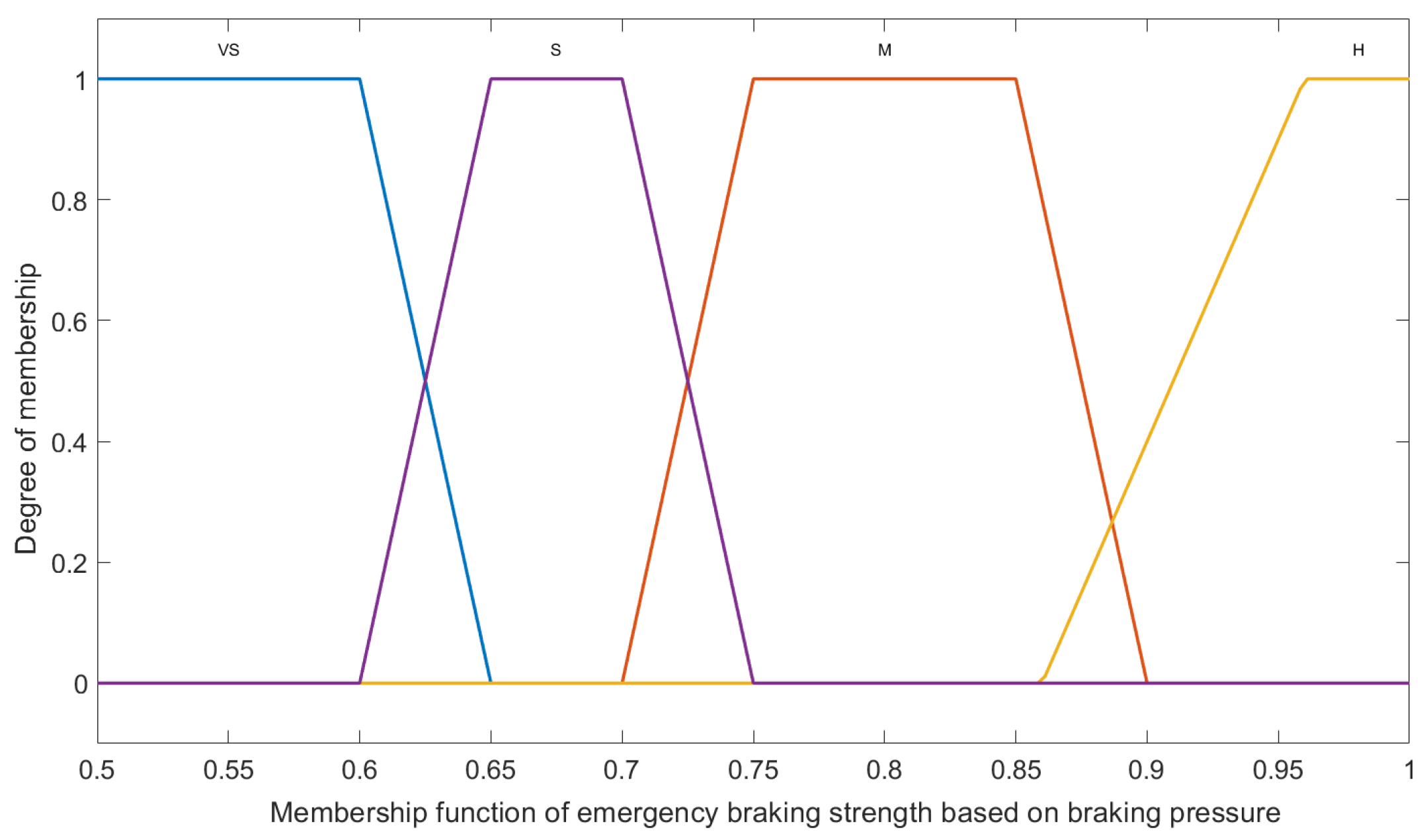
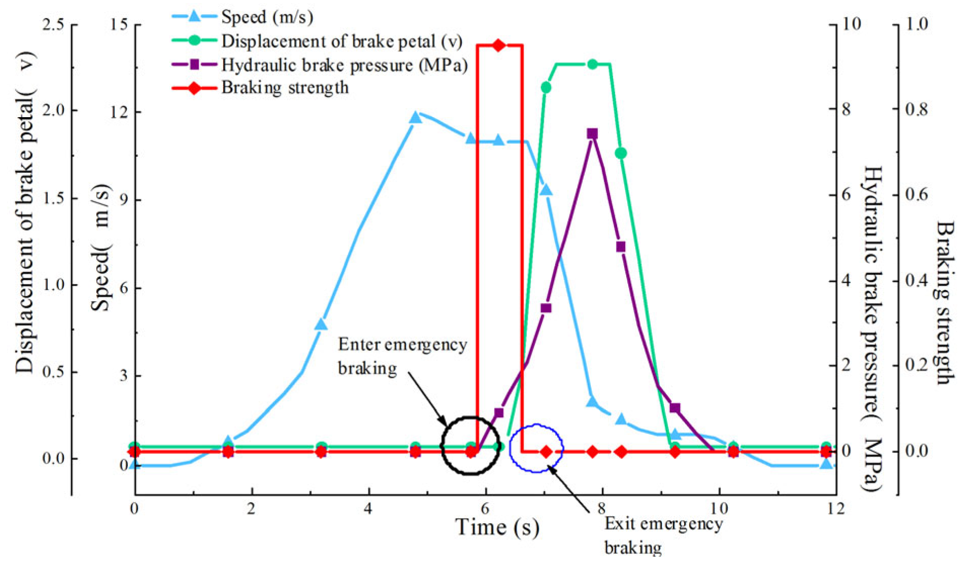
3.5. Emergency Braking Intention Identification Based on Hydraulic Braking Pressure
4. Simulation Analysis
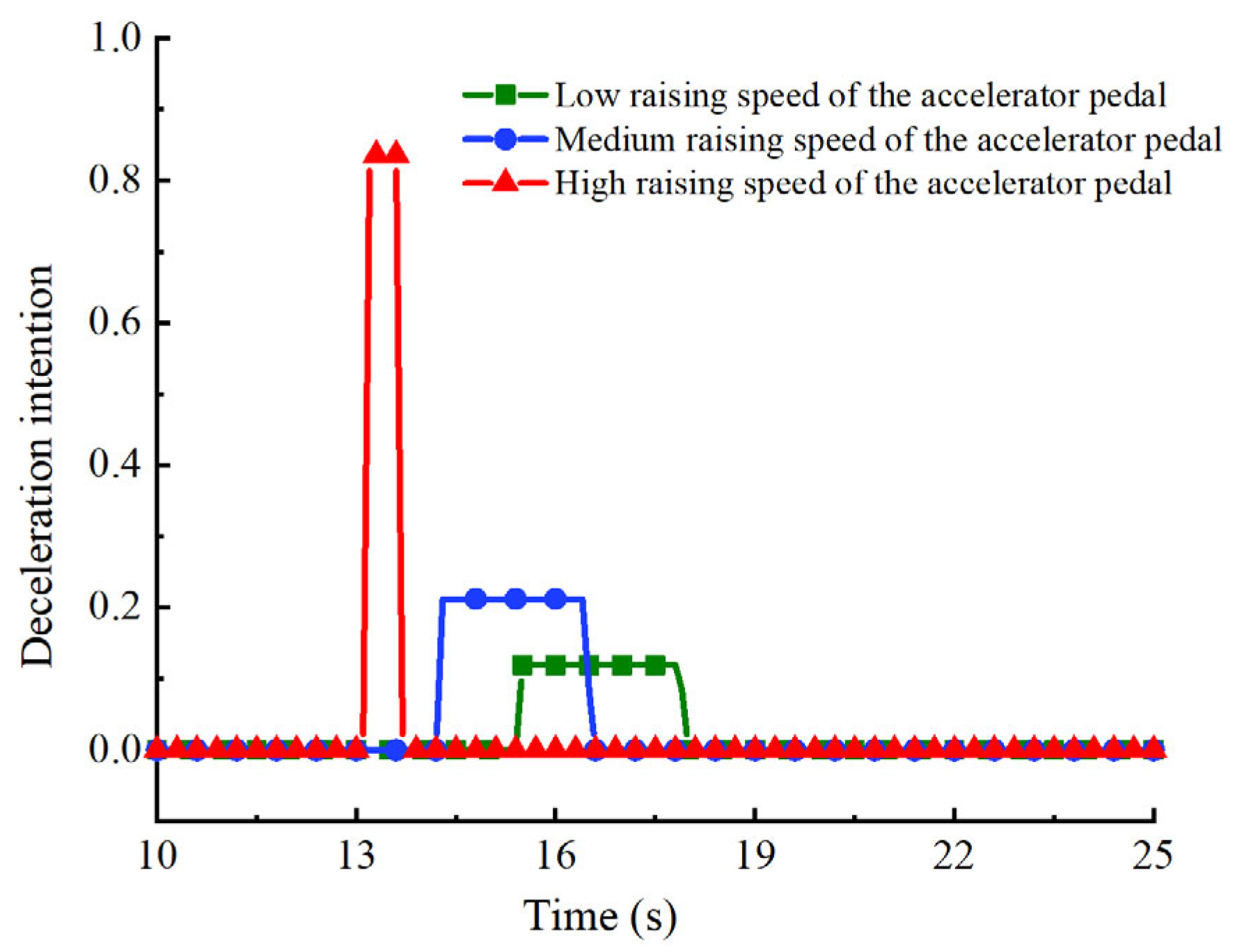
- (1)
- Simulation results of deceleration intention identification based on accelerator pedal.
- (2)
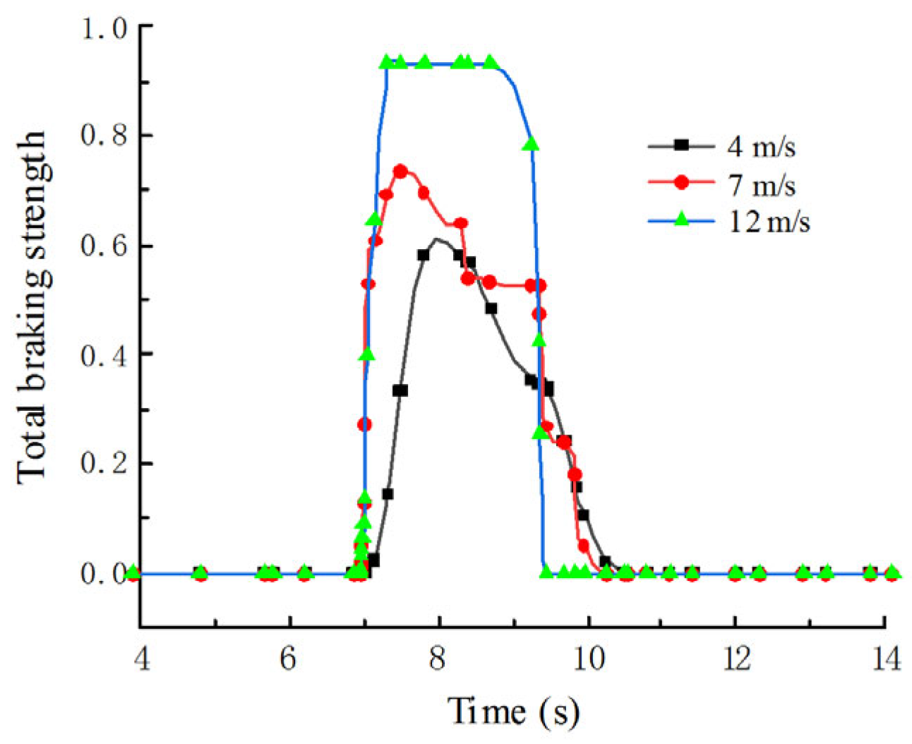
- Simulation results of braking intention identification based on brake pedal.
- (3)
- Simulation results of sliding brake intention identification.
- (4)
- Emergency braking intention identification based on hydraulic brake pressure
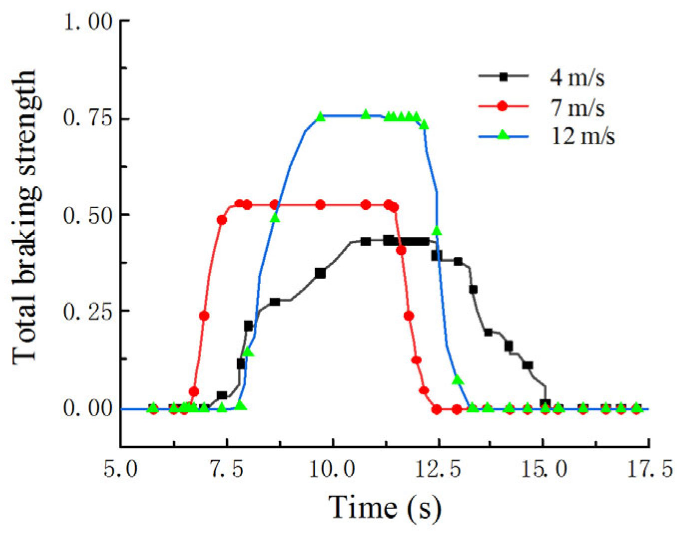
5. Prototype Test
6. Conclusions
Author Contributions
Funding
Institutional Review Board Statement
Informed Consent Statement
Data Availability Statement
Conflicts of Interest
References
- Lin, Y.; Lin, T.; Chen, Q.; Li, Z.; Fu, S.; Ren, H.; Guo, T. Research Progress on Key Technologies of Electric Construction Machinery. Chin. Hydraul. Pneum. 2021, 45, 1. [Google Scholar]
- Xu, S.; Zhao, X.; Yang, N.; Bai, Z. Control Strategy of Braking Energy Recovery for Range-Extended Electric Commercial Vehicles by Considering Braking Intention Recognition and Electropneumatic Braking Compensation. Energy Technol. 2020, 8, 2000407. [Google Scholar] [CrossRef]
- Yildiz, A.; Özel, M.A. A Comparative Study of Energy Consumption and Recovery of Autonomous Fuel-Cell Hydrogen–Electric Vehicles Using Different Powertrains Based on Regenerative Braking and Electronic Stability Control System. Appl. Sci. 2021, 11, 2515. [Google Scholar] [CrossRef]
- Huang, S.; Wu, X.; Lin, T.; Chen, Q.; Ren, H. Recovery and Control Strategy of Electro-Hydraulic Composite Braking Energy for Electric Loader with Braking Intention Recognition. Appl. Sci. 2023, 13, 9853. [Google Scholar] [CrossRef]
- Yang, Y.; He, Y.; Yang, Z.; Fu, C.; Cong, Z. Torque coordination control of an electro-hydraulic composite brake system during mode switching based on braking intention. Energies 2020, 13, 2031. [Google Scholar] [CrossRef]
- Chen, L.; Yu, Y.; Luo, J.; Xu, Z. Target Oil Pressure Recognition Algorithm for Oil Pressure Following Control of Electronic Assisted Brake System. Machines 2023, 11, 183. [Google Scholar] [CrossRef]
- Wang, B.; Wang, L.; Tang, X.; Yang, S. A braking intention identification method based on data mining for electric vehicles. Math. Probl. Eng. 2019, 2019, 7543496. [Google Scholar] [CrossRef]
- Zheng, H.; Ma, S.; Fang, L.; Zhao, W.; Zhu, T. Braking Intention Recognition Algorithm Based on Electronic Braking System in Commercial Vehicles. Int. J. Heavy Veh. Syst. 2019, 26, 268–290. [Google Scholar] [CrossRef]
- Li, X.; Ma, J.; Zhao, X.; Wang, L. Research on Characteristic Parameter Selection and Attention-GRU-Based Model for Braking Intention Identification. Proc. Inst. Mech. Eng. Part D J. Automob. Eng. 2023, 09544070221145474. [Google Scholar] [CrossRef]
- Lv, C.; Xing, Y.; Lu, C.; Liu, Y.; Guo, H.; Gao, H.; Cao, D. Hybrid-Learning-Based Classification and Quantitative Inference of Driver Braking Intensity of an Electrified Vehicle. IEEE Trans. Veh. Technol. 2018, 67, 5718–5729. [Google Scholar] [CrossRef]
- Xing, Y.; Lv, C. Dynamic State Estimation for the Advanced Brake System of Electric Vehicles by Using Deep Recurrent Neural Networks. IEEE Trans. Ind. Electron. 2019, 67, 9536–9547. [Google Scholar] [CrossRef]
- Ma, C.; Wang, X.; Xu, T.; Wang, J.; Feng, P. Research on a Novel Electro-Hydraulic Brake System and Pedal Feel Control Strategy. Proc. Inst. Mech. Eng. Part D J. Automob. Eng. 2023, 237, 1681–1694. [Google Scholar] [CrossRef]
- Diederichs, F.; Schüttke, T.; Spath, D. Driver Intention Algorithm for Pedestrian Protection and Automated Emergency Braking Systems. In Proceedings of the 2015 IEEE 18th International Conference on Intelligent Transportation Systems, Gran Canaria, Spain, 15–18 September 2015; IEEE: Piscataway, NY, USA, 2015; pp. 1049–1054. [Google Scholar]
- Ju, J.; Feleke, A.G.; Luo, L.; Fan, X. Recognition of Drivers’ Hard and Soft Braking Intentions Based on Hybrid Brain-Computer Interfaces. Cyborg Bionic Syst. 2022, 2022, 9847652. [Google Scholar] [CrossRef]
- Kavala Sen, D.; Yildiz, A.; Kopmaz, O. Optimal Design of a Five-Bar Planar Manipulator and Its Controller by Using Different Algorithms for Minimum Shaking Forces and Moments for the Largest Trajectory in a Usable Workspace. Machines 2022, 10, 971. [Google Scholar] [CrossRef]


| Stage | Contents | Motion State | Stage | Contents | Motion State |
|---|---|---|---|---|---|
| 1 | Forward with no load | Accelerating | 4 | Forward with full-load | Accelerating |
| Uniform speed | Uniform speed | ||||
| Decelerating | Decelerating | ||||
| 2 | Loading | Stop | 5 | Unloading | Stop |
| 3 | Backward with full-load | Accelerating | 6 | Backward with no load | Accelerating |
| Uniform speed | Uniform speed | ||||
| Decelerating | Decelerating |
| Stepping Speed of Accelerator Pedal V | NH (Negative High) | NM (Negative Medium) | NL (Negative Low) | NS (Negative Small) | NO (Negative Zero) |
|---|---|---|---|---|---|
| Deceleration intention | O | S | L | M | H |
| Deceleration Strength | Deceleration Intention | ||||
|---|---|---|---|---|---|
| Vehicle speed | O | S | L | M | H |
| L (low) | VS | SL | SL | M | SH |
| M (Medium) | VS | SL | L | M | SH |
| H (High) | SL | L | M | H | SH |
| Braking Intention | Brake Pedal Displacement | ||||
|---|---|---|---|---|---|
| Displacement change rate | O | S | M | H | VH |
| S (Small) | O | VS | S | M | H |
| M (Medium) | O | VS | M | H | VH |
| H (High) | O | S | H | H | VH |
| Braking Strength | Braking Intention | |||||
|---|---|---|---|---|---|---|
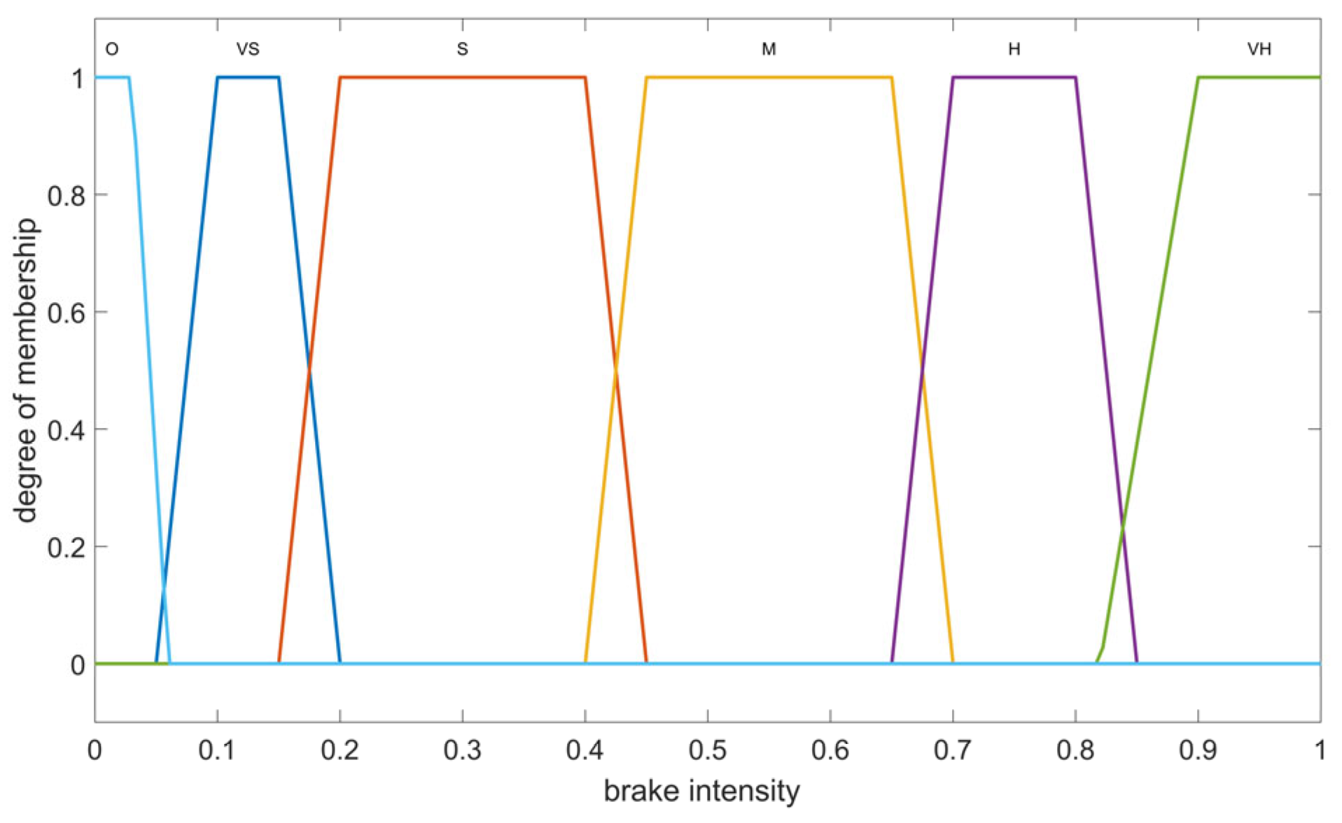
| Vehicle speed | O | VS | S | M | H | VH |
| S (Small) | O | VS | S | S | M | VH |
| M (Medium) | O | VS | S | M | H | VH |
| H (High) | O | S | M | H | H | VH |
Disclaimer/Publisher’s Note: The statements, opinions and data contained in all publications are solely those of the individual author(s) and contributor(s) and not of MDPI and/or the editor(s). MDPI and/or the editor(s) disclaim responsibility for any injury to people or property resulting from any ideas, methods, instructions or products referred to in the content. |
© 2023 by the authors. Licensee MDPI, Basel, Switzerland. This article is an open access article distributed under the terms and conditions of the Creative Commons Attribution (CC BY) license (https://creativecommons.org/licenses/by/4.0/).
Share and Cite
Ye, Y.; Wu, X.; Lin, T. Braking Intention Identification Strategy of Electric Loader Based on Fuzzy Control. Appl. Sci. 2023, 13, 11547. https://doi.org/10.3390/app132011547
Ye Y, Wu X, Lin T. Braking Intention Identification Strategy of Electric Loader Based on Fuzzy Control. Applied Sciences. 2023; 13(20):11547. https://doi.org/10.3390/app132011547
Chicago/Turabian StyleYe, Yueying, Xia Wu, and Tianliang Lin. 2023. "Braking Intention Identification Strategy of Electric Loader Based on Fuzzy Control" Applied Sciences 13, no. 20: 11547. https://doi.org/10.3390/app132011547
APA StyleYe, Y., Wu, X., & Lin, T. (2023). Braking Intention Identification Strategy of Electric Loader Based on Fuzzy Control. Applied Sciences, 13(20), 11547. https://doi.org/10.3390/app132011547