1. Introduction
The most common control method of the PMSM is vector control. The principle is based on coordinate transformation, which aligns the magnet’s magnetic field with the rotating coordinate system to achieve the decoupling of the magnetic field and torque. This results in AC motors exhibiting similar performance to DC motors. Direct torque control (DTC) is a recently developed AC frequency-control technology with high performance, proposed by Takahashi [
1] and Depenbrock [
2]. Compared with vector control technology, it does not have pulse-width modulations (PWM), current control, and park transform. DTC employs Bang-Bang control (hysteresis control) to generate PWM signals, ensuring optimal control of the inverter’s switching states, thus achieving high dynamic performance in torque [
3]. DTC abandons the decoupling concept, replacing rotor flux orientation with stator flux orientation. It eliminates the need for complex coordinate transformations, reducing the system’s dependency on motor parameters and enhancing computational speed. By real-time monitoring of stator voltage and current, torque and flux amplitudes are calculated and compared with the predetermined torque and flux values. The resulting differences are utilized for direct control of flux and torque [
4]. Hence, DTC features a simple control structure and excellent dynamic performance. However, DTC produces variable switching frequencies with large fluxes and torque ripple, which result in high-frequency noise. Researchers have studied some strategies, e.g., employing space vector modulation (SVM) to control voltage inverters [
5] or introducing duty-cycle control [
6] and DTC based on sliding mode speed controller [
7] to solve these problems.
Due to the characteristics of permanent-magnet synchronous motors (PMSM), such as nonlinearity, strong coupling, and numerous variable parameters, traditional vector control methods like Field-Oriented Control (FOC) and Direct Torque Control (DTC) often fall short of meeting the demands of high-performance, high-precision, and robust operation [
8]. To enhance the control performance of PMSMs, numerous researchers have proposed advanced control strategies, including intelligent control [
9], sliding mode control [
10], and predictive control [
11]. Intelligent control methods encompass neural networks and fuzzy control, among others. The essence of intelligent control lies in autonomy, mimicking human thought processes to achieve intelligent control. For instance, Han et al. [
12] achieved precise observation of electromagnetic torque using a BP neural network. Chaoui and others [
13] proposed a continuously adaptive RBF network for speed control of interior permanent-magnet synchronous motors, simplifying the control structure while enhancing control accuracy. However, intelligent algorithms such as neural networks and machine learning typically require extensive training data, exhibiting limited robustness and flexibility in PMSM systems [
14]. When dealing with multiple objectives, some intelligent algorithms necessitate retraining, adding to the workload. Moreover, the significantly increased computational complexity due to intelligent algorithms hampers the motor’s ability to respond rapidly [
15].
Recently, the emergence of the MPTC has attracted more and more attention from academia and industry. It is considered an effective alternative to the classical magnetic field-oriented control [
16]. This has been validated in [
17].The results indicate that MPTC achieves steady-state performance similar to FOC but with faster dynamic response. Furthermore, it provides superior current quality and lower computation time. Additionally, MPTC allows the design of cost functions to assess the impact of voltage vectors [
18]. These cost functions offer flexibility, making it easy to incorporate system constraints. In [
19], the torque, stator flux, and neutral point potential of MPTC were kept more accurately within their hysteresis bounds while pursuing the lowest switching frequency. MPTC can still combine multiple control objectives [
20], thereby achieving comprehensive system performance optimization.
Regardless of the above advantages, the MPTC faces several challenges [
21]. The computational burden increases exponentially with the prediction steps, so long-horizon predictions are difficult to perform in real time for commonly used numerical processors. Secondly, one optimal vector is applied to the PMSM in each period, and the control period is confined by huge computation, which leads to a high torque ripple. Thirdly, the switching frequency, torque, and flux linkage are adjusted by weighting factors of the cost function, so it is difficult to achieve a low switching frequency with a low torque ripple. Researchers have proposed various methods to decrease calculations, torque ripple, and switching frequency during the last decade.
The optimal voltage vector is preselected and stored in a lookup table to reduce the computational effort [
22], while the memory occupation grows with increased prediction steps and variables following exponential law. Ref. [
23] adopts a second optimization and a new simplified search strategy to make the output voltage vector closer to the actual optimal solution. In this case, a more suitable voltage vector is applied in each sampling period. The simplified search strategy reduces calculation time by cutting down the number of candidate voltage vectors without affecting drive performance. The computational complexity is reduced by setting the switching table, and ripples are reduced under the premise of satisfying torque performance without increasing sampling time [
24]. Wang et al. [
25] used the DeadBeat (DB) technology to optimize the selection process of voltage vectors. The method only needs to compute three voltage vectors at each prediction step.
Various solutions have been proposed to decrease torque ripple, e.g., the zero-voltage vector combined with active voltage vectors [
26], the combination of two active voltage vectors [
27], the graph algorithm to select the predicted current error for each sampling period [
28], switched reluctance motors with low measurement effort [
29], and the multiple vector-based model-predictive control [
30]. Typical solutions to reduce the switching frequency of the MPTC include adjacent voltage vectors selected in each step [
31], control current loop [
32], virtual three-level MPFC (V3-MPFC) [
33], and a new MPTC strategy based on the virtual voltage vector mode, that is, the cost function is used to optimize the switching mode between two adjacent control cycles in real time [
34]. Although the aforementioned methods can separately reduce calculations, torque ripple, or switching frequency, it is difficult to improve these targets simultaneously.
An improved MPTC model was established based on the DTC and MPC in the work. A multi-objective screening method was used to replace the selection of weighting factors in the cost function, which avoided unnecessary simulations and experiments when weighting factors were determined. The method used the genetic algorithm, and the relationship between all objective functions was equivalent. Besides, electromagnetic torque and the stator magnetic flux linkage were used as tracking targets. Simulation results showed that the newly proposed MPTC had a faster torque response, fewer computations, less torque pulsation, and good dynamic and steady-state performance. The method did not require offline optimization like other MPTC algorithms. It simplified unnecessary calculations in prediction and increased the processing performance of the algorithm. The proposed method enabled decoupled and rapid control of motor torque and stator magnetic flux, which made it applicable to various PMSMs regardless of their specific parameters.
The rest of the work is arranged as follows.
Section 2 presents the model of the PMSM.
Section 3 proposes a multi-objective sorting algorithm based on the traditional MPC.
Section 4 builds a simulation model and compares the proposed algorithm with traditional MPC algorithms. The experimental results are presented in
Section 5. The conclusions are given in
Section 6.
3. Proposed MPTC with Multi-Objective Ranking
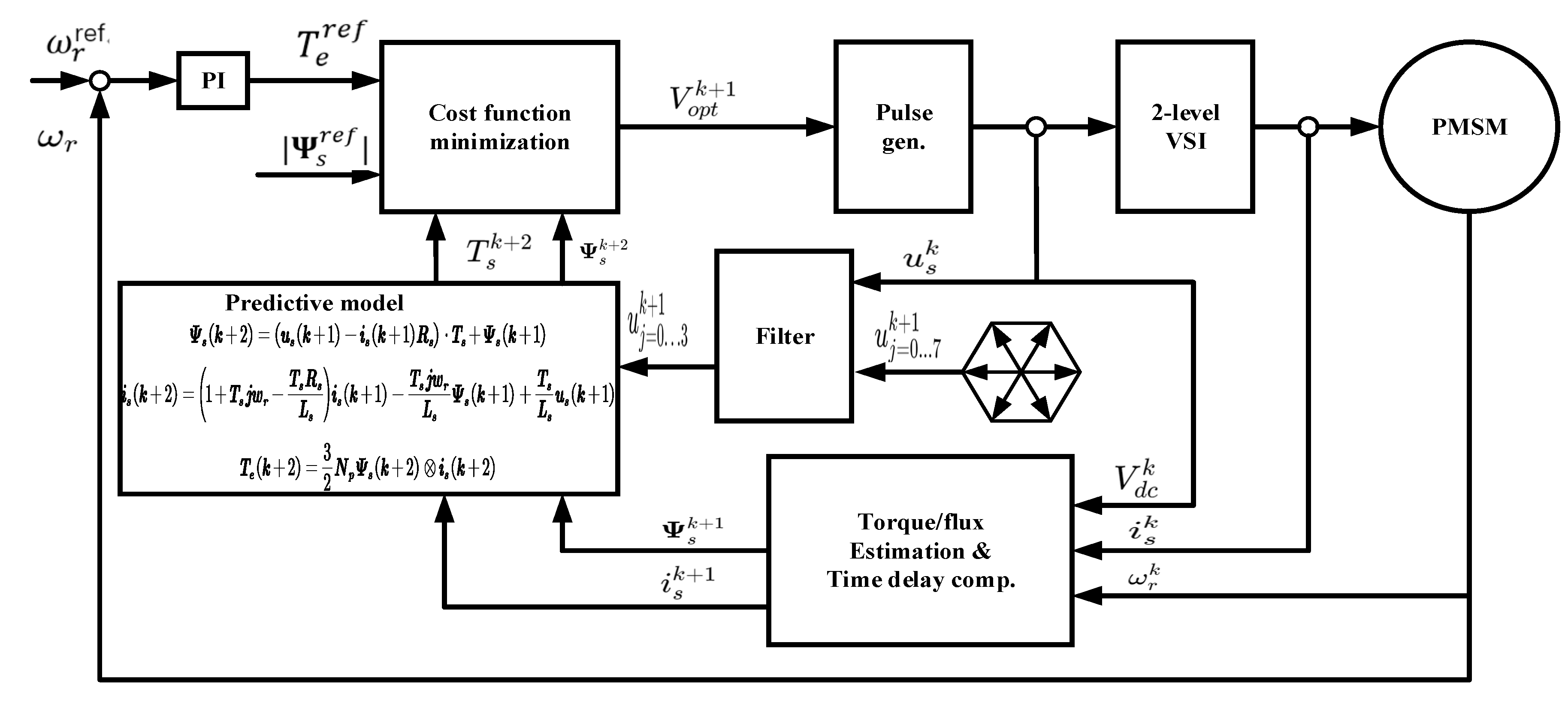
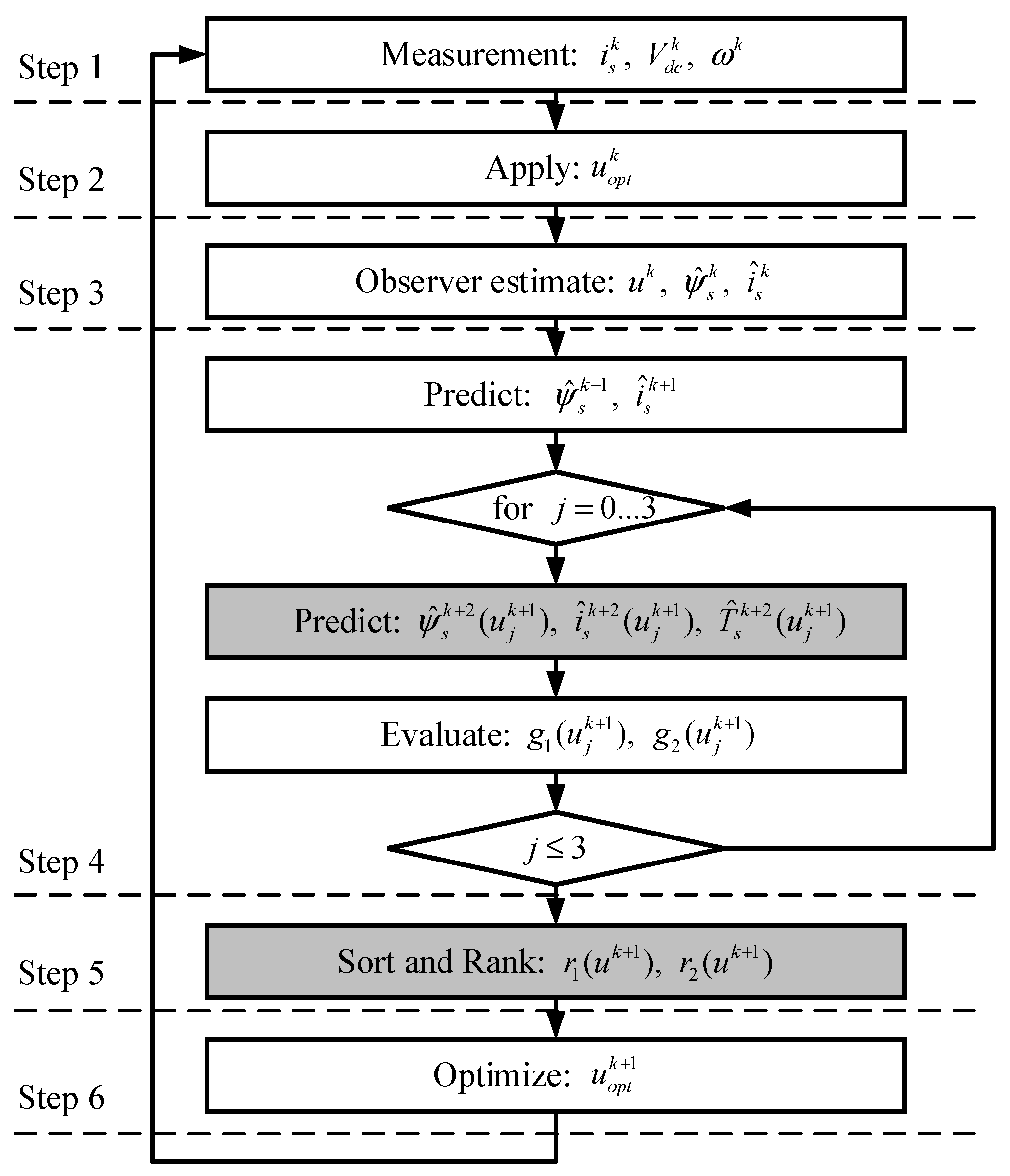
Figure 2 shows the block diagram of the improved MPTC frame. This algorithm is primarily composed of four components: motor output observation, delay compensation, prediction process, and cost function calculation.
(1) Motor output observation: The three-phase voltage quantities and current flow information of the motor are measured, which are then fed into the Lomborg observer. This calculates the stator flux and the torque at the current time. Simultaneously, the reference speed and actual speed are input into the PI controller, yielding the current electric torque reference value .
In the case of utilizing a conventional PI controller, the expression for the speed loop controller is as follows:
where
represents the mechanical angular velocity of the motor;
denotes the moment of inertia;
is the damping coefficient;
is the stator flux;
is active damping;
is the polar logarithm;
represents the proportional gain of the Pl controller; and
is the integral gain of the Pl controller.
Compared to the typical method of tuning PI controller parameters using classical two-degree-of-freedom systems, this approach to parameter tuning is straightforward, and the relationship between parameter adjustments and the system’s dynamic quality is clear;
(2) Delay compensation: In the case of model predictive torque control, the selection of the optimal voltage vector for the next moment based on the sampled value at the current moment will “expire” due to the delay due to the existence of the computer command cycle. As a result, the optimal voltage vector acting at time k will be delayed to act at time (k + 1), which is inaccurate for the motor control system. Therefore, delay compensation is usually used to calculate the optimal voltage vector at the (k + 1) moment in advance to eliminate the inaccuracy of the voltage vector due to the delay in calculation.
To further enhance the precision of model predictions and achieve complete compensation, this study employs a two-step computational delay compensation approach: firstly, estimating the stator current and the stator flux at the k instant, and then predicting and based on Equations (4) and (5). Subsequently, the variables at time (k + 1) serve as initial conditions for predicting (k + 2);
(3) Forecasting process: The traditional MPTC control algorithm requires rapidly substituting 8 fundamental voltage vectors into the prediction model to calculate the stator flux and torque values generated under the influence of each voltage vector. However, this computational task is evidently complex. In this study, a graph algorithm is employed to reduce the 8 fundamental voltage vectors to 4. These reduced vectors are then applied to the prediction model to calculate the stator flux and torque values at time (k + 2) for subsequent cost function screening;
(4) The calculation of cost function. In the context of multi-objective optimization problems for permanent-magnet synchronous motors (PMSM), the weighting coefficients in traditional model-predictive torque control (MPTC) serve as a crucial method to coordinate various control objectives. These coefficients enable standardization of control variables while allowing for the assignment of varying importance levels to different controlled variables based on practical requirements. However, the design of these weighting coefficients necessitates extensive offline optimization efforts. To tackle the challenges related to the cumbersome design of weighting coefficients and the difficulty in determining optimal coefficients, this paper proposes a multi-objective sorting optimization method. Each control objective function is independently evaluated and transformed into dimensionless sorting results. By comprehensively considering the sorting values of the objective functions, the method selects the voltage vector with the lowest sorting value, thereby identifying the voltage vector that minimizes torque error and stator flux error. This approach employs a ranking-based multi-objective optimization approach, replacing traditional cost functions in achieving the optimal solution for voltage vectors.
The aforementioned four components constitute the working principle of MPTC. These components are interrelated and jointly determine the success of MPTC. However, in practical applications within motor control systems, the successful design of delay compensation and cost functions plays a pivotal role in determining the system’s control performance.
3.1. Flux and Torque Estimation
Direct torque control measures the motor voltage and current, which can estimate the flux and torque of the motor. It often requires multiple segment estimations in the full speed range. The Lomborg observer has high accuracy in the medium- and high-speed range [
36]. A current correction link is introduced, and a modified integration algorithm is used to eliminate the drift effect caused by pure integration. An observer model based on the PMSM model (1) is established as
where
is the estimated state variable.
Parameter
G needs to be determined to ensure the fast convergence and robustness of the parameter identification system. The Lomborg observer requires that the real part of the eigenvalues of the state matrix of the error space equation is less than zero, which can be used to select
G within the range. Of course, constant gain matrix
G can also be used to improve the stability of the observer (10) [
37]:
where
b is the negative constant gain. The approach used in the work can be implemented straightforwardly. In addition, it ensures the observer’s convergence and stability across the entire speed range, particularly under medium and high speeds.
3.2. Error Prediction Based on the Graph Algorithm
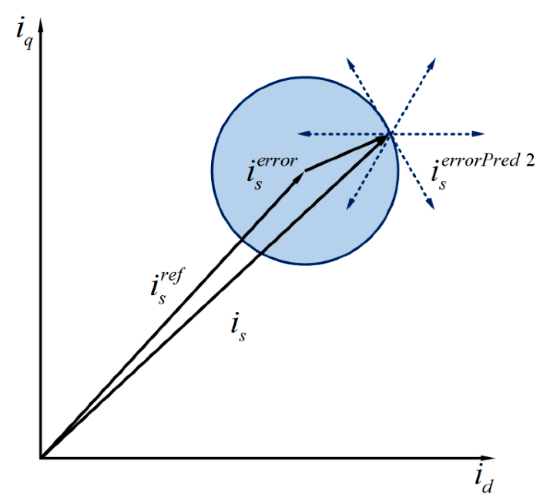
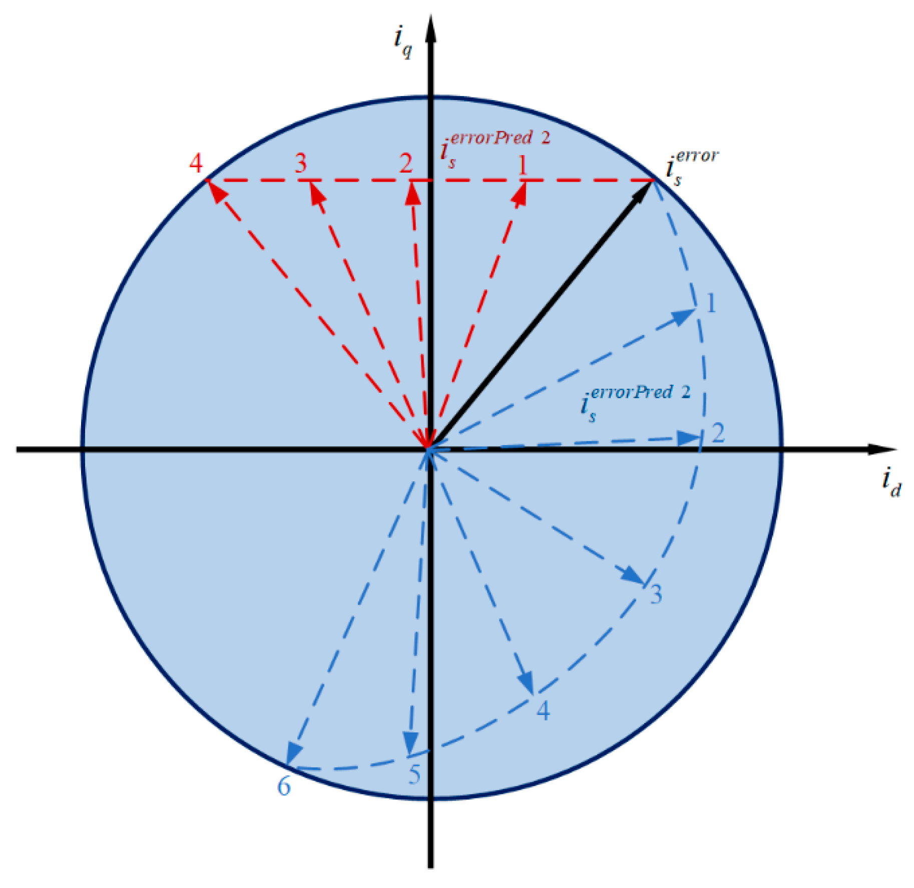
The last inverter-switching state and current error are obtained at the beginning of the control cycle. Then, the load model is used to predict the current error for the next sampling cycle. Eight possible error trajectories are plotted according to eight different switching states (
Figure 3). If only two of these exist with possible solutions within the circle, the solution maximizing the duration within the current error circle should be selected (the blue dashed line in
Figure 4). A larger number of samples can remain within the current error circle.
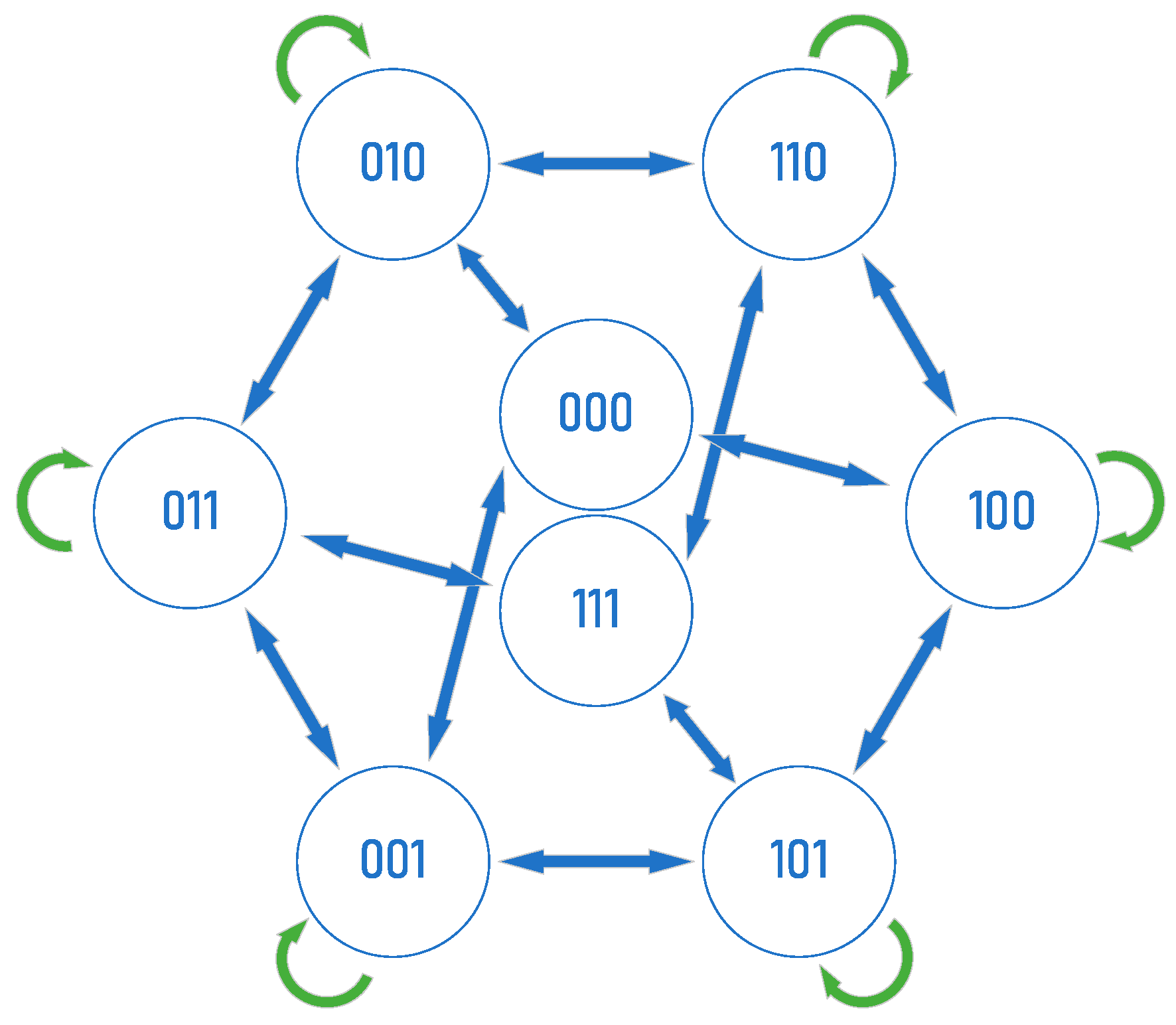
However, predicting errors in these eight cases is time-consuming and unnecessary. It is necessary to avoid complete dc-link voltage jumps in the common mode voltage (CM) as well as 2/3 dc-link voltage jumps in the common mode voltage (CM), i.e., bipolar switching should be avoided. Two opposing voltage vectors increase current ripples; therefore, these voltage vectors are not selected in the following cycle. The base number is reduced for predicting the quantity calculation, and the number of predictions is thus reduced from
to
for a two-level inverter. The actual switching state of the inverter and the vectors that can be applied next are represented using a diagram (
Figure 5). The picture illustrates that the switching frequency is finite, as only one change in the switch is allowed per sampling cycle.
3.3. File Formats for Graphics
Stator current
and stator flux
at moment
are taken as initial variables in MPTC for the stator flux and torque to track their corresponding reference values. A physical prediction model is used to predict stator flux
and electromagnetic torque
at moment
. The following cost function is defined to minimize the error between the estimated stator flux and torque and the reference value:
where
and
are calculated by Equations (7) and (8). Torque reference
is generated by the external PI speed controller, and
is the stator flux reference.
is the weight factor of the stator flux, which should be adjusted frequently:
where
and
are the nominal values of torque and stator flux linkage, respectively.
can be adjusted to track different targets.
is determined using a genetic algorithm and is typically debugged offline. It significantly affects the performance of the controller.
A certain time delay exists between the control voltage calculated from the previous sample and the actual voltage by considering the limited time available for the control algorithm to execute at each step during hardware processing. Requisite compensation is necessary to mitigate the impact of delay on MPTC performance. A model-based prediction method is used to reduce the impact of the delay in the work. Stator current
and stator’s magnetic flux linkage
at the
instant areestimated and predicted for
and
according to (5). The variables at the
moment is used as initial conditions for the instant
prediction to obtain the final values of
and
. The minimized cost function is now defined by
Then, the stator voltage vector that minimizes (13) is selected to be output at the next sampling time:
where
is the optimal output of the stator voltage vector at the next sampling time.
3.4. Multi-Objective Ranking-Based Strategy
The multi-objective sorting-based MPTC, aiming to eliminate the dimensional and magnitude differences between motor torque and flux, independently evaluates the control effectiveness of each control variable after obtaining the predicted values of the control variables. These variables are then ranked using dimensionless sorting results to represent the control effectiveness for the control objectives [
38]. The optimal solution is obtained by minimizing the sorting results. The complete sorting algorithm mainly consists of the following four steps: (1) Prediction: Utilize the prediction model to forecast the future states of the system; (2) Evaluation: Independently assess each control objective to quantify the effectiveness of different voltage vector control strategies; (3) Sorting: Rank the performance of different voltage vectors based on their control effectiveness, assigning corresponding sorting results accordingly; (4) Optimization solving: Sum up the sorting results obtained by different voltage vectors for each control objective [
39]. By obtaining the total sorting result and through minimizing this total sorting result, one determines the optimal voltage vector.
The MPTC needs to choose the minimization of the cost function of multiple objectives within each sampling period. It can be expressed by two different cost functions:
The torque and stator’s flux-related errors are represented by and , respectively. The MPTC needs to be evaluated for each possible voltage vector.
During the sorting phase, the sorting criteria are defined as follows: utilizing graph algorithms to reduce the eight basic voltage vectors to four voltage vectors and calculating the cost function values for each voltage vector. In ascending order [
40], voltage vectors with smaller errors are assigned lower ranks, starting from 0 and incrementing by 1, with a maximum rank of 4. Based on a unified sorting rule for all control objectives, the voltage vectors have the same range, which is [0, 4], and have been dimensionlessly processed [
8]. The torque sorting results for each voltage vector and the stator magnetic flux sorting results are denoted as
and
, respectively, that is,
where
is the voltage vector to be evaluated and
and
are the ordering values of
and
, respectively; the ordering values are dimensionless variables. Considering the ordering values of the two objective functions comprehensively, the minimum voltage vector of torque and flux errors is selected based on the lowest sorting value. Torque and flux variables are tracked by selecting the voltage vector with the lowest-ranking mean value to select the optimal voltage vector. Then, the proposed optimization method based on ranking is as follows:
Based on the genetic algorithm, the concept of average ranking is introduced using average criteria. It can be simplified to the sum of
and
(
Figure 6) because the two optimization objectives are equivalent.
3.5. Sorting Algorithm
Although the dimensionless sorting results in multi-objective sorting-based MPTC resolve the cumbersome issue of designing weight coefficients, they introduce additional sorting computations, increasing the computational burden. Most papers employ classical sorting algorithms such as bubble sort or quicksort [
41] for sorting optimization. Although these methods yield sorting results under the current control objectives, the relative positions of voltage vectors are altered, necessitating data exchange operations during the process. In this study, to meet the specific requirements of multi-objective sorting MPTC, the Tim-sort sorting algorithm is employed.
Tim-sort is an adaptive, hybrid, stable sorting algorithm that combines the Merge-sort and Insertion-sort algorithms. The core of the algorithm is to extract descending arrays and upgrade them in ascending order, as arrays are all partially ordered by nature. Arrays can be sorted in less time than a quick sort. The Tim-sort algorithm used can be described in the following order:
Run: Run an incrementing or strictly decrementing sub-string, where the increment includes the case where the two elements are equal. Decreasing Run is reversed to an increasing sequence in a real program;
Stack: Used to save each Run;
Sort 1. Iterate through the array collecting each element to form Run based on a specific condition;
Sort 2. It is put on the stack after obtaining Run;
Sort 3. If Run at the top of the stack meets the merge condition, the merge operation is triggered, that is, two adjacent Runs are merged to form one Run.
Merging is performed in real time in Tim-sort, and the discovery of each Run may potentially initiate merging. The stability of the algorithm can be ensured during merging. The algorithm has an average time complexity of and a worst-case time complexity of , which requires comparisons. However, it can run in linear time with a time complexity of in the optimal-case scenario where the input is already sorted. Compared with other sorting algorithms, Tim-sort is far more efficient.
4. Simulation and Results Discussion
4.1. Simulation Study
Simulations were carried out in the MATLAB/Simulink environment to verify the effectiveness of the proposed multi-objective sequencing MPTC. The parameters in
Table 1 were used for the simulation tests.
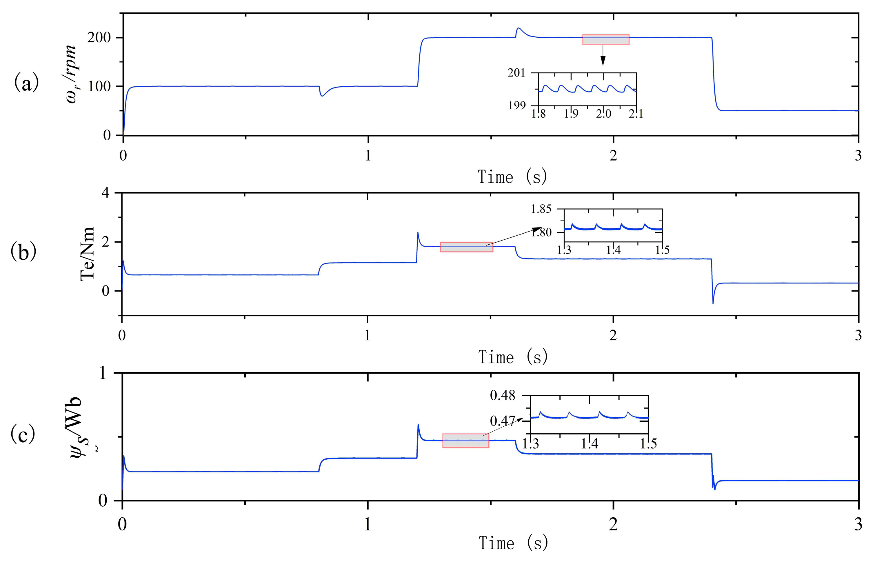
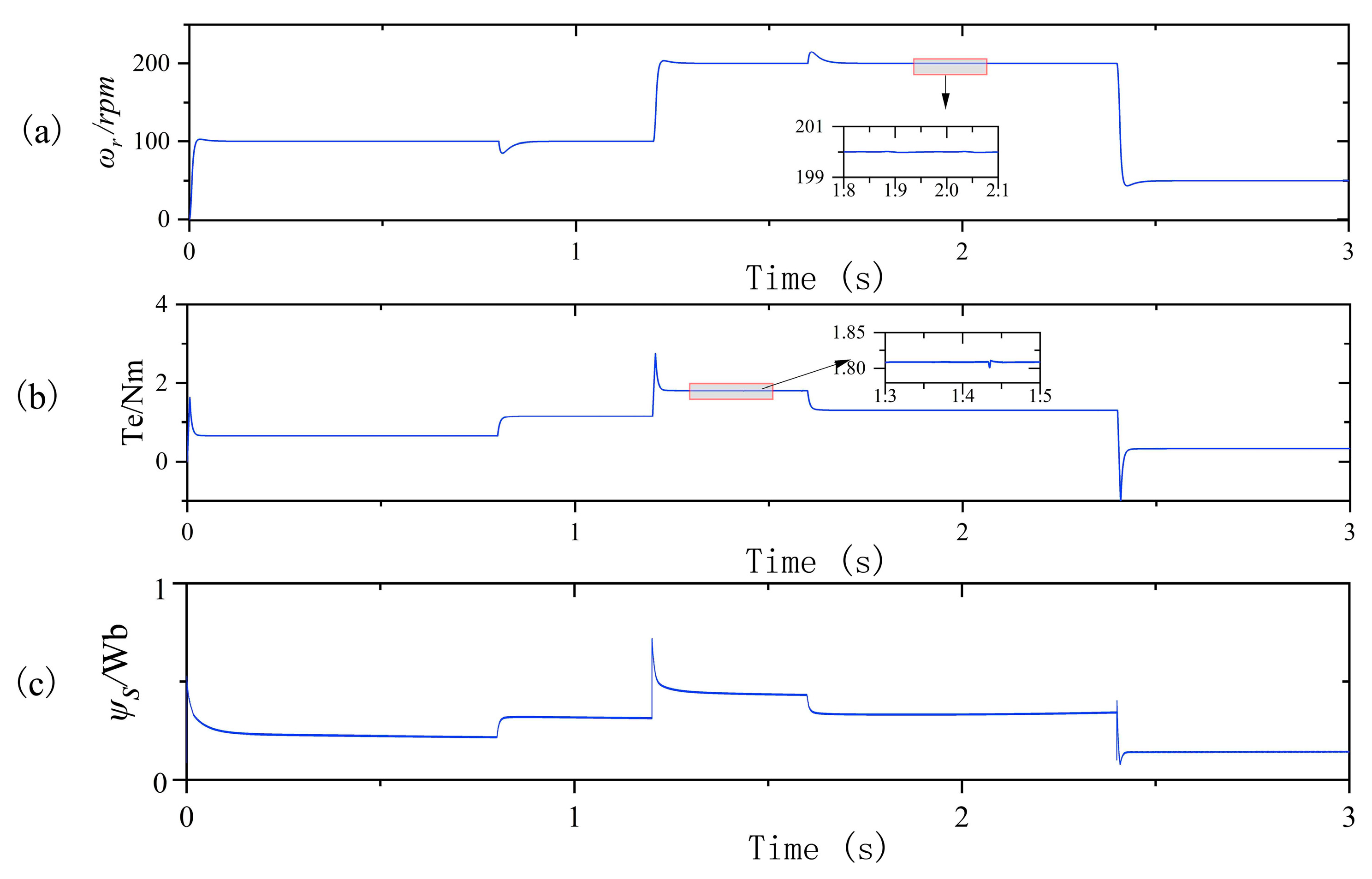
The simulation settings are as follows. The motor accelerates from rest to 100 r/min within 0–1.2 s. The load torque of 2 Nm is added at 0.8 s, and the speed increases to 200 r/min at 1.2 s. The load is removed at 1.6 s, and the speed decreases to 50 r/min from 2.4 s onwards. A speed reference and a rated load are added to the system to show the overall control behavior of the system. The goal is the evaluation of the overall control behavior. The stator’s reference magnetic flux is maintained at 0.94 Wb, which is slightly lower than the rated value to avoid magnetic saturation.
Figure 7 and
Figure 8 present the simulation results.
Firstly, the system has significantly improved steady-state performance. Secondly, the output torque can accurately track the load torque TL with fewer fluctuations than the conventional MPC. Fluctuations in the steady state also disappear, and the amplitude of the stator flux has similar characteristics to the torque-tracking curve.
Since the speed control is carried out by a PI controller, the speed exhibits a smooth response in terms of dynamic performance. It has a short rise time during acceleration and deceleration, and the overshoot of the motor speed is minimal. When the load is suddenly applied and removed, the speed fluctuates slightly. However, it can be stabilized at the set speed soon, indicating that the robustness of the system is high. The new proposed strategy has a faster dynamic response to torque.
The method proposed in the work has lower switching times, and the switching frequency is reduced by an average of 41.2% compared to the conventional MPC control (
Figure 9). However, it is still higher than PMSM with the DTC.
4.2. Weight Factor
The conventional MPC incorporates a weight factor before the stator’s flux error in the cost function. Traditionally, this factor requires offline adjustment. However, considering that all variables within this function possess identical properties, there is no necessity for weight factor adjustment. Extensive simulations and experimental tests are performed to determine the appropriate weighting factors in related studies. Moreover, these weighting factors are highly sensitive to different motor parameters.
Table 2 lists the comparison parameters for the main values obtained by the traditional MPC and the proposed MPTC.
A comparison of the results obtained by the multi-objective ranking method with other methods for optimizing the weighting factor offline shows similar results. However, the algorithm mentioned in the work does not require tedious offline calculations and weighting-factor optimization.
4.3. Comparison of Sorting Algorithms
A robust approach is proposed for addressing multi-objective systems by eliminating relative differences between variables in the cost function and the need to choose weighting factors. Each voltage vector is assigned its corresponding priority utilizing an average ranking of multiple voltage vectors. Prior classification of voltage vectors is essential to derive the optimal voltage vector, as excessive calculation of unnecessary ones can waste computational resources. The classification of the graph algorithm reduces the predicted eight voltage vectors to four, which significantly reduces hardware resource consumption during experimentation. Minimization of the torque error and flux error can be considered optimization objectives in the software algorithm in addition to average sorting.
The conventional MPC algorithm increases significant computational overhead, which prompts a comparative analysis of timing performance in the work. Processing time for each segment of the algorithm is considered for its 1000 iterations to reflect its calculation time (
Table 3).
There is little difference in time required for the measurement and speed control between these control methods: for an estimation and delay compensation; for a prediction. Time required for the sorting method proposed in the sorting phase is , where and for subsumption sorting and sorting minimization, respectively. Since the conventional MPTC has no sorting process, the time required is . This is the only drawback of the algorithm. However, the processing time of the sorting method depends on programming. Tim-sort sorting is more stable for larger sequences like this one, especially for the implementation of the sorting algorithm and sorting optimization.
The maximum value of calculation time in each case is considered in the actual implementation of the algorithm since maximum processing time is minimum sampling time that can be used. Most studies on motor control algorithms use two-level three-phase inverters with the predicted number of voltage vectors in each control cycle (
n = 8).
Table 4 presents a comparison between the proposed MPTC and traditional MPC as well as the fast-sorting algorithm when the prediction range is set (
h = 1) and control target
i = 2. The subsumption algorithm requires 16 calculations, while the sorting minimization algorithm only needs 4 calculations, which results in a total of 20 computations.
Computational complexity increases dramatically when prediction ranges, control targets, or different inverters are added. The data filtering of initial variables reduces the computational basic numbers, which significantly affects algorithm performance. Of course, more sophisticated algorithms can be used to address issues such as target priority, frequency variation limits, and prediction range adaption. However, the work improves the weighting factor selection and processing based on the existing MPC and compares each one’s feasibility.
5. Experimental Evaluation
This chapter designs an experimental platform for the PMSM based on the STM32F4 series chip. The experimental platform for the control system is introduced from the hardware circuit and software program. Both of them are software–hardware development platforms based on MATLAB/Simulink (2022b), offering C language rapid generating and online calibration functions. Relevant testing methods are designed to verify the control performance of the two algorithms, and the results are analyzed and discussed.
5.1. Test Bench Introduction
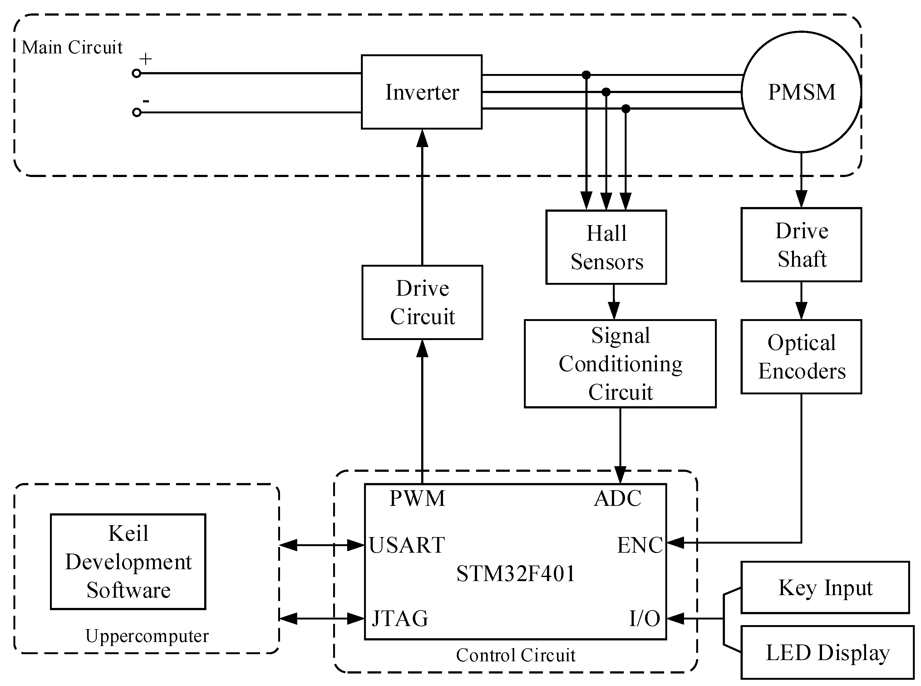
Figure 10 shows the flow of the PMSM control system, and its working principle is summarized as follows. The Hall sensor samples the electrical signals from the main circuit, from where it is converted into an analog signal and input to the MCU after signal conditioning. The incremental optical encoder measures the actual speed of the PMSM. It is converted into a digital quantity and input to the MCU chip. The MCU control chip calculates and outputs three-phase PWM signals to the inverter drive circuit according to input data and the program set by the PC. Drive signals are reinforced to regulate the PMSM. CubeMX5.1.0 is used as the software development platform to improve system performance. As a graphical configuration tool compatible with the master control MCU chips, it generates the initialized C code for processors with Cortex-M cores and allows the step-by-step configuration of STM32 microcontrollers and microprocessors.
The steps are as follows: (1) Select an STM32 microcontroller, microprocessor, or development platform compatible with the desired peripherals; (2) Users can configure GPIO pins, set up the system’s clock, allocate peripherals, and define various parameters for the MCU; (3) Users configure relevant files in the code generation area to generate corresponding initialized C code; (4) The debugger is connected to the JTAG interface of the MCU using Keil uVision5 software. The program is then downloaded to the STM32F4 chip and debugging is performed. The emulator model used in the work is ST-Link, which can transmit data signals and convert protocols. The PMSM can be controlled in this way.
Figure 11 illustrates the connection method between software and hardware.
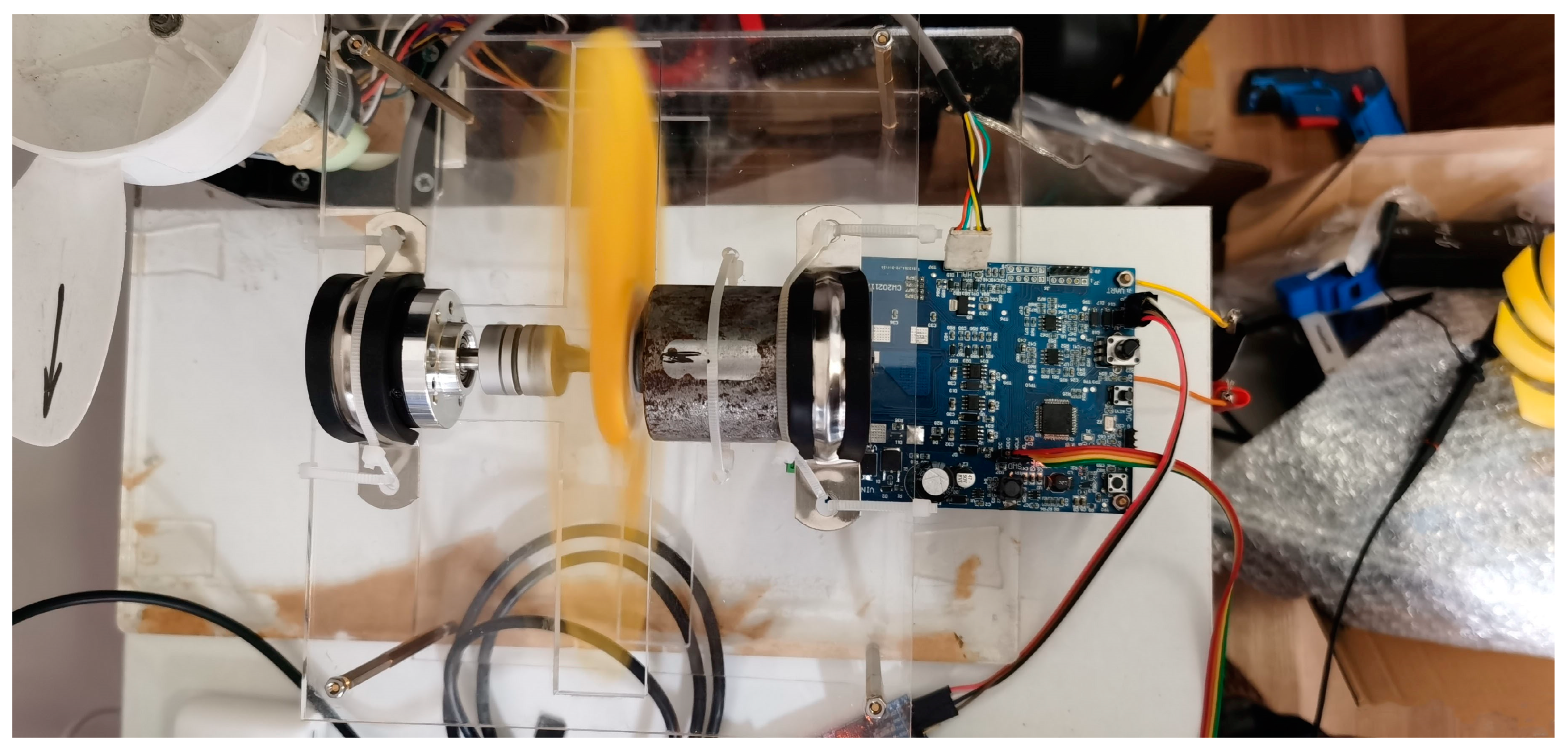
Figure 12 shows the PMSM and its control system used in the experiment. This consists of a regulated DC power supply, control board, PMSM, simulator, computer, and oscilloscope. The software algorithms designed earlier are burned into the system. The computer acts as the host machine to send commands and perform parameter debugging in this experimental setup, while the MCU serves as the lower computer to control the PMSM.
5.2. Experiment Results and Discussion
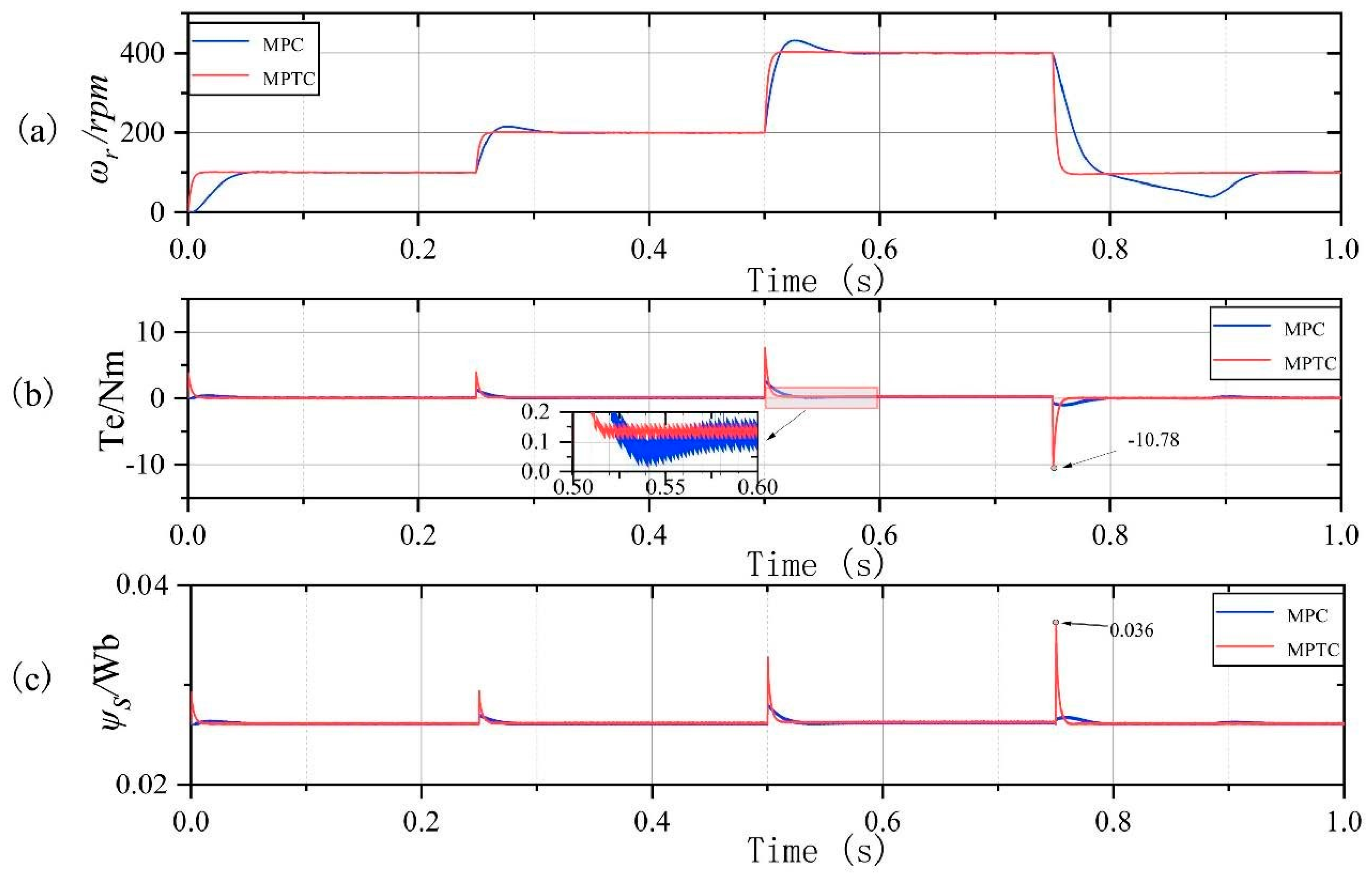
The initial speed is set to 100 rpm in the experiment, and the motor starts in the unloading condition. It continues to accelerate until reaching the reference speed. The reference speed is immediately increased to 200 and 400 rpm at 0.25 and 0.5 s, respectively; it is reduced back to 100 rpm at 0.75 s.
Figure 13 shows the experimental results.
According to the experimental results, it takes 0.05 s for the motor to reach steady-state speed with the MPC control method during low-speed operation. However, it takes a longer time to reach a steady state during medium to high-speed operation, with an overshoot of approximately 9.7%. When the speed drops sharply, the MPC method exhibits a waveform where the speed cannot be tracked for approximately 0.13 s. It then waits for an additional 0.06 s before re-tracking the reference speed. On the other hand, regardless of the speed stage of the motor, it can reach the reference speed within 0.02 s without any overshoot under the MPTC method. Therefore, the MPTC designed in the work demonstrates faster and better speed-tracking performance compared to the traditional MPC control method.
The MPC exhibits lower torque switching in terms of the torque response during speed transitions. The MPTC shows larger torque values at each speed-switching point, and the difference between peak torque and speed switching is truly correlated. However, MPTC can recover reference torque more rapidly than the MPC when the local torque waveform is observed. Additionally, the steady-state torque fluctuation in the MPTC is significantly smaller than that using the MPC, with an average reduction in ripples of approximately 58.4%. As for the stator flux, both methods maintain stability. MPTC exhibits higher peaks at speed switching points, but they remain within the allowable range of the motor. The dynamic and steady-state characteristics of the MPTC are similar to torque characteristics. Therefore, the MPTC designed in the work demonstrates better steady-state torque performance compared to the traditional MPC.
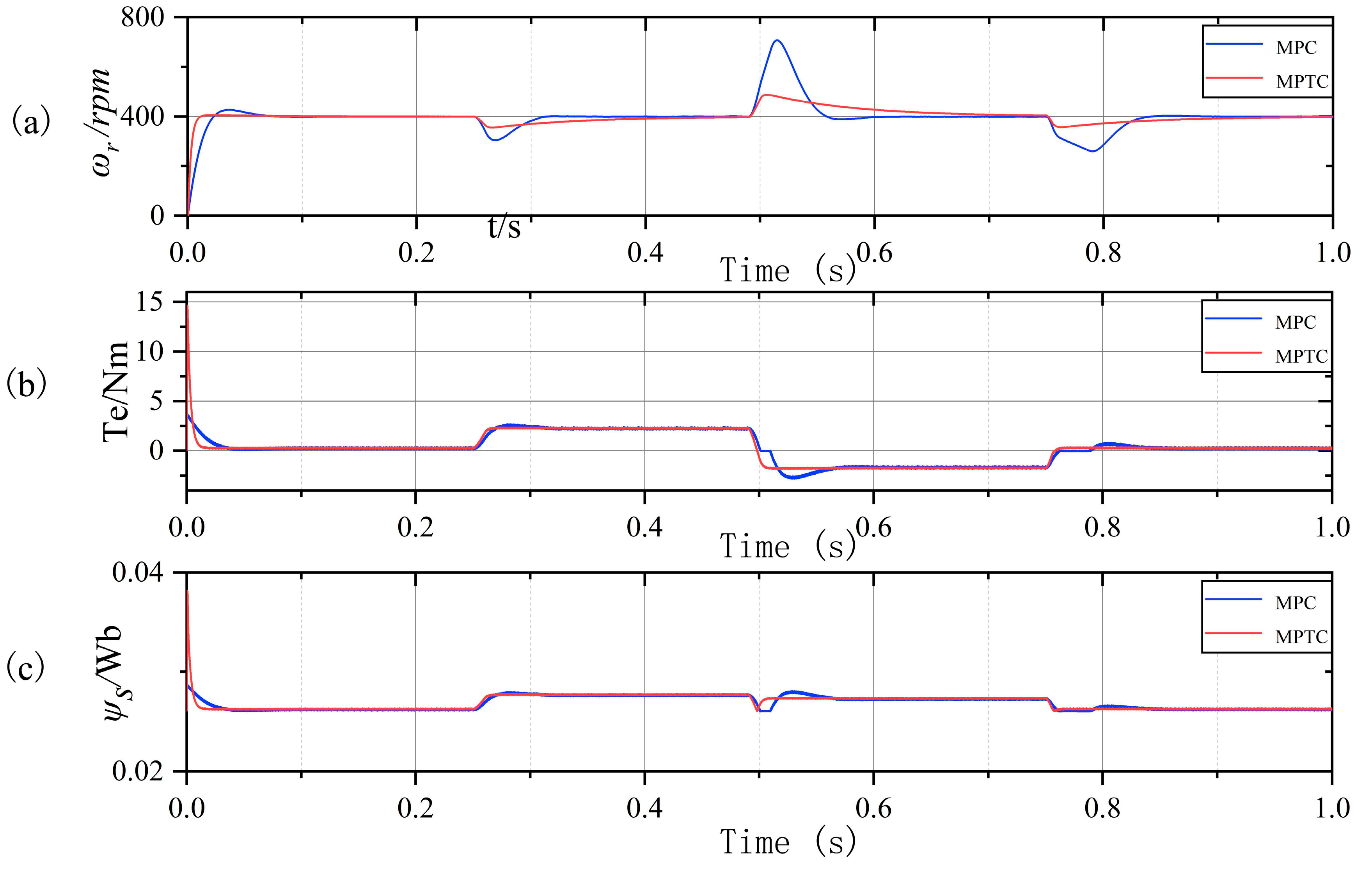
Given an initial reference speed of 400 rpm, the motor is started without loads until the reference speed is reached. The load torque of 2 Nm is applied to the PMSM at 0.25 s after a period of no-load operation, and the reverse torque of −2 Nm is immediately loaded at 0.5 s. Load torque is withdrawn at 0.75 s to observe the performance of the motor.
Figure 14 shows the experimental results.
The experimental results indicate that, when the load is suddenly increased, the motor speed decreases by a maximum of 157 rpm with the MPC; however, it only decreases by 78 rpm with the MPTC. When torque suddenly transits from load torque to dragging torque, the speed increases by 316 rpm with the MPC, whereas the MPTC method shows an increase of only 107 rpm. The MPC experiences a period of speed drop after torque is removed, which lasts until approximately 0.04 s before it continues to track the reference speed. On the other hand, the speed tracking of the MPTC is similar to the curve of the first sudden increase in torque. Therefore, the MPTC designed in the work exhibits stronger resistance to load disturbances compared to the traditional MPC.
Although the MPC does not exhibit high peak torque from the torque-response perspective, it shows approximately 12% overshoot when torque is tracked during the load application. When torque reverses, the MPC maintains zero torque for approximately 0.2 s, which rapidly increases the speed. Approximate 0.07 s are taken for the MPC to track back to load torque. The same situation occurs when load torque is removed. On the other hand, the initial MPTC exhibits peak torque due to the given initial speed of 400 rpm, and high torque is utilized to quickly bring the motor to the reference speed. Torque returns to no-load torque after 0.02 s, and its response is significantly faster than that of the MPC. The MPTC can promptly respond to the load torque application, torque switching, and load-torque removal without overshooting. The flux characteristics resemble the torque characteristics. MPC performance declines when the loading direction is switched, while the MPTC can stably track load torque. Therefore, the MPTC designed in the work demonstrates more stable torque-load performance compared to the MPC.


