Article

Numerical Investigation of the Pile–Soil Interaction Problem under Dynamic Loads

Department of Civil Engineering, Nisantasi University, 34398 Istanbul, Turkey
*
Author to whom correspondence should be addressed.
Appl. Sci. 2023, 13(21), 11653; https://doi.org/10.3390/app132111653
Submission received: 22 September 2023 / Revised: 17 October 2023 / Accepted: 23 October 2023 / Published: 25 October 2023

Abstract

:
One of the most important problems of geotechnical engineering is the design of pile foundations. Piles are generally designed for vertical and horizontal static loads. However, it is important to design piles against dynamic loads in regions with high seismicity. This study verified a centrifuge experiment obtained from the literature with a finite element program. With the kinematic interaction analyses performed for this purpose, the effect of parameters such as layered soil, groundwater, pile stiffness, and earthquake acceleration were investigated numerically. According to the results obtained, it was understood that the earthquake magnitude is the most important parameter in kinematic interaction analyses. In addition, in layered soil conditions, the fact that 75% of the pile length is in the weak soil creates the most unfavorable situation. It was observed that pile stiffness and groundwater level also have certain effects on the kinematic interaction.

1. Introduction

One of the most important problems of geotechnical engineering is the construction of structures on soils that have problems in terms of their bearing capacity and settlement. In cases where the weak soil layers are not located too deep and the building load is low, solutions can be produced in such problematic soils by using soil improvement methods. However, if the weak soil layers are too deep and the building load is high, the application of pile foundation systems becomes mandatory. There are many methods in the literature regarding the design of piles under static loads, and the design principles are discussed in detail in many international standards. However, although the piles have sufficient strength under static loads, they can be damaged due to dynamic loads. In this respect, it is important to accurately reflect the behavior of piles under dynamic loads in the design.
Determining the behavior of structures constructed on pile foundations, especially under earthquake loads, becomes a more complex design problem. During earthquakes, piles are exposed to kinematic conditions due to the lateral shaking of the surrounding soil and to inertial interaction due to superstructure vibrations. Since these effects occur simultaneously during an earthquake, it is difficult to consider them separately. Studies have observed that piles at shallow depths cannot transfer inertia forces, and kinematic conditions are more effective at these depths [1,2]. There are many numerical and experimental studies on kinematic interaction analyses of piles in the literature [3,4,5,6,7,8,9,10,11,12,13].
Kaynia [3] investigated the dynamic behavior of group piles in a semi-infinite soil condition. The study examined the effects of soil elasticity and the hardness–flexibility matrices of the pile on the deformations occurring at the pile–soil interface. The results showed that group piles’ behavior is frequency-based; the interaction factors obtained in the study are valid in homogeneous soil condition, and their validity decreases in non-homogeneous soil condition.
Fan et al. [4] numerically investigated the kinematic conditions in group piles under harmonic S waves. Within the scope of the study, pile–pile and pile–soil interactions were examined. The kinematic conditions were investigated parametrically by changing the pile configurations in the soil condition idealized as homogeneous two-layer. In the study, it was seen that the natural soil profile was effective at all frequencies, and the pile group configuration, number of piles, and distance between piles did not affect the lateral displacements but were effective in the rotation of the pile cap.
Kavvadas and Gazetas [5] examined the behavior of free cap piles under kinematic conditions. The study was carried out on a two-layer soil with a large difference in sliding velocities. The results obtained from the study showed that the differences in shear wave velocities affected the bending moment significantly. In pile design, the moments that will occur in the transition layers directly affect the design.
Castelli et al. [8] investigated the kinematic behavior of single piles under seismic loads with a finite element program. In the study, a free field soil (without piles) and piles were modeled to evaluate the kinematic conditions. The results obtained showed that in the transition region to soft soil, the moments increased significantly, and hinges formed within the pile.
Luo et al. [11] investigated the soil–pile–structure interaction with an improved equivalent linear model and a modified Drucker Prager soil model with the help of a three-dimensional finite element program. In the analyses, it was seen that the nonlinearity of the soil directly affected the behavior, and lower acceleration responses were obtained if the equivalent model was used. As a result of the study, it was seen that non-linear soil models must be used in interaction analyses and that they affected the results.
Garala and Madabhushi [14] investigated the behavior of pile foundations in soft clays under dynamic loads with centrifuge experiments. The experiments were carried out in a group of single piles and 1 × 3 row piles with different spacing. As a result of the study, the importance of a nonlinear analysis in characterizing the earthquake behavior of soft clays was emphasized. It has been shown that the response of clay depends on both the earthquake intensity and the shear strength and stiffness of the clay layer. This situation affects the response of individual piles and pile groups and has been observed to cause greater amplification in small earthquakes.
Sahare et al. [15] investigated the soil–pile kinematic interaction problem with dynamic centrifuge experiments. For this purpose, they took into account the slope angles of liquefiable soil subjected to four successive earthquake shakings with increasing acceleration amplitude. According to their results, it was understood that soil surface slopes had a significant effect on the kinematic bending moments of the piles. Additionally, the kinematic moments with dominant lateral propagation produced during the first shaking were larger compared to the three subsequent shakings. This shows that the complex kinematic interaction does not depend only on the amplitude of base excitation but on the magnitude of lateral spread.
Yamashita et al. [16] investigated the seismic response analysis of piled raft foundations combined with cement deep mixture walls (DMWs) under strong earthquakes with a three-dimensional finite element program. Moderate earthquake motions from the 2011 Tohoku earthquake were used to verify the DMWs and ground deformation parameters. Earthquakes with a return period of 500 years were reproduced as strong earthquake movements. According to the dynamic analysis results, it was observed that DMWs significantly reduced the bending moments near the pile head. Additionally, the amplification of the acceleration response spectrum of the raft with DMWs was found to be significantly lower than that of the raft without DMWs for long periods of 1–2 s.
Kaynia [17] investigated the monopile–soil interaction in layered soils with a numerical model that calculates the rotation and horizontal responses as a function of the frequency. Analyses in both frequency and time domains showed how the kinematic interaction affected the earthquake loads applied to the offshore wind turbine. According to the results obtained, tower response and bending moments are greater when kinematic interaction is included in SSI analyses in all soil profiles. The effect of kinematic interaction appeared to be greater in stiffer soils.
Al-Jeznawi et al. [18] developed a three-dimensional finite element model to evaluate soil pile performance based on the 1 g shaking table test. Kobe earthquake records were used in the analysis. Lateral ground acceleration was used to simulate seismic effects. The numerical model takes into account the nonlinearity of the material and the nonlinearity of the contact surfaces between the pile and the soil. As a result of the study, it was observed that the maximum pile settlement varied between 5 and 10 s during the magnification of the applied ground motion. The pile and soil were subjected to pressure and tension cycles due to increased acceleration. Analyses showed that shear stresses decreased as a result of dynamic excitation.
Mallick et al. [12] examined the dynamic effects of the pile–soil system under axial loading in liquefiable soil layers using the 3D finite element method. In the study, an advanced soil strength law based on a multi-surface plasticity model was used for soil–fluid interaction and pore water pressure development. It was observed that as the axial load applied to the pile increased, the liquefaction depth decreased. It was also observed that the bending moment of the pile under axial loading may be higher than in the non-liquefiable case.
Garala et al. [13] examined the effect of pile spacing on the dynamic behavior of pile groups by performing specially designed dynamic centrifuge experiments on pile foundations embedded in a two-layer soil profile. According to the experimental results, it was observed that pile-group effects decrease with the increase in pile spacing, which leads to larger kinematic pile bending moments in a pile group due to reduced pile–soil–pile interactions. However, reduced pile-group effects were observed in the widely spaced pile group, resulting in larger bending moments compared to the closely spaced pile group. It was also concluded that a single pile always had larger bending moments than the pile groups tested.
Hu et al. [19] investigated the nonlinear stochastic seismic behavior of piles using a three-dimensional finite element program. For this purpose, the finite element model was validated using full-scale lateral load test results in the literature. Then, solutions were created using a validated three-dimensional numerical model and stochastic seismic response analysis. In the study, the mean, standard deviation, and probability density function of pile settlement and the dynamic reliability of piles for various performance requirements were obtained. The stochastic seismic response analytical method proposed in this study is considered to provide a convenient and comprehensive way to quantify various uncertainties and their corresponding effects on the seismic performance of pile foundations.
Huang et al. [20] investigated the dynamic behavior and parameter effects of inclined straight group piles under the influence of an earthquake using a finite element program. In the analysis, it was seen that the inclination angle of the inclined piles under the influence of the earthquake significantly affected the seismic behavior of the pile group. It was observed that when the inclined pile inclination angle was 5°, the deformation resistance of the inclined pile group foundation was improved, and the load distribution at the pile head was more reasonable.
Tipsunavee et al. [21] investigated the effects of two types of improvement methods with cement mixture in terms of reducing and redistributing the forces occurring in piles. In the study, the dynamic response of the soil–pile–structure interaction system of a high-rise building under seismic load was investigated using numerical analysis. Real-time earthquake motion was used in the analysis. According to the results obtained, it was observed that in the case of improvement, the bending moment and shear force magnitude in the piles decreased and were distributed equally along the upper region of the piles. This shows that the contact between piles reduces the bending moment and shear forces.
Engineering design references regarding pile–soil interactions generally consist of different regulations and codes. There are regulations and codes in the literature such as the National Earthquake Hazards Reduction Program (NEHRP) [22], American Association of State Highway and Transportation Officials (AASHTO) [23], Europe Code (EUROCODE) [24], and Turkish Building Earthquake Regulations (TBDY) [25]. In these regulations and codes, the methods to be followed in the design of kinematic interactions are presented, but there is no directly recommended design approach. Although it is recommended in NEHRP to consider the base plate average, embedment depth, and the effect of pile foundations in kinematic interaction analyses, no analytical relationship is presented. In the regulation prepared by AASHTO, nonlinear behavior methods that are valid for offshore oil platforms are proposed. Although this regulation refers to the creation of p-y curves for sand and clays, no direct correlation is presented for the kinematic interaction. In Eurocode and Turkish regulations, rules regarding the conditions under which kinematic interaction analyses should be performed are included, and references are made to the methods to be used. There is no direct analytical method available in either regulation.
When studies in the literature are evaluated, the studies generally focus on numerical modeling and use the finite element program in the analyses. In some of these studies, case studies were discussed, while in others, the effects of various parameters were investigated by verifying an experimental study. In parametric studies, issues such as pile placement, group effects, and geometric effects were mostly addressed.
The results obtained from studies in the literature show that the damage caused by kinematic interactions occurs at the pile head in soft soils and in the intermediate ground layers where strength differences occur. Studies on kinematic interaction analyses in the literature that take parametric effects into consideration are limited. In this study, an experimental study in the literature was verified with a finite element program, and then the effects of soil stratification, groundwater level, pile stiffness, and earthquake acceleration parameters were investigated.
In these parameters investigated within the scope of the study, the effect of material properties and earthquake magnitude were emphasized. Kinematic effects, which are among the most important factors affecting the pile–soil interaction problem, are mostly affected by material properties and earthquake magnitudes. The most important innovation that adds a difference to this study is the investigation of the parameters that will directly affect the kinematic interaction with numerically verified experimental data.

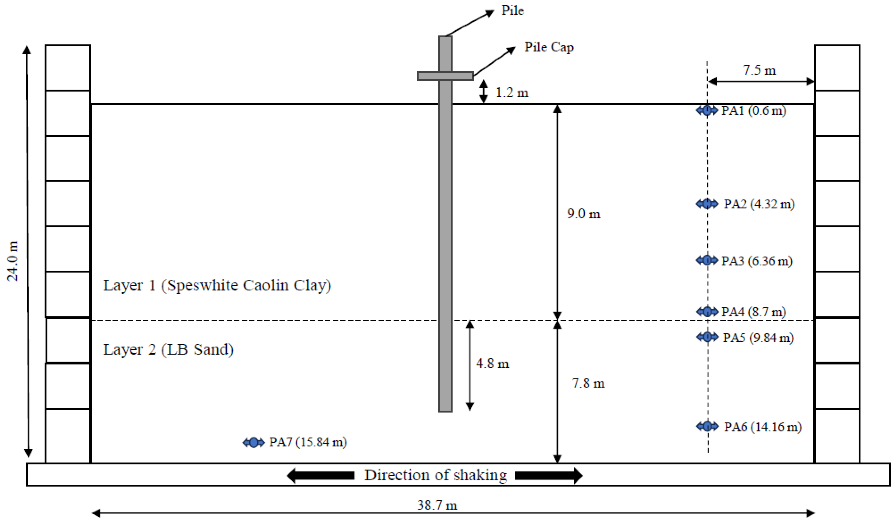
2. Description of Problem

In this study, the behavior of piles under the influence of dynamic loads was investigated under kinematic conditions. For this purpose, a finite element program was used to model an experimental study from the literature. After the experimental results were verified numerically using the finite element program, the effects of different parameters on the behavior were investigated. The experimental study modeled in the study was carried out by Garala et al. [13].
The experimental studies considered within the scope of this study were carried out in a centrifuge setup. In the experimental study, the behavior of single piles and 3 × 1 row group piles was examined. Only the behavior of single piles was investigated in the numerical modeling. The schematic representation of the setup of the experiments is shown in Figure 1 [13]. The experiments were carried out in a layered soil condition consisting of soft clay and dense sand. Poorly graded Fraction-B Leighton Buzzard (LB) sand was used as the sand layer, and the sand properties are presented in Table 1. The properties of Kaolin clay used in the experiments [11] are given in Table 2. The bending moments were measured using strain gauges on the aluminum piles used in the experiments. In addition, accelerations in the soil were measured using piezometric accelerometers (named as PA) along the depth of the soil (Figure 1). The results obtained from the numerical analyses carried out within the scope of this study were verified by comparing the bending moments obtained from the experiments with the accelerations occurring in the soil.

3. Finite Element Analysis

The two-dimensional Plaxis 2022 2D finite element program was used in the numerical modeling of the study by Garala et al. [13]. The Plaxis program is a finite element program that uses advanced soil models to solve deformation and stability problems and allows for the simulation of static and dynamic loading conditions. The most important advantage of the program is that it allows for the most realistic modeling of soil and loading conditions and is user-friendly. When deciding to use the Plaxis 2D program, which performs nonlinear analysis, in this study, the modeling capabilities of the program were taken into account. These include many aspects such as using advanced ground models, simulating earthquakes in the time domain, and creating dynamic boundary conditions. In addition, the compatibility of studies in the literature regarding such analyses was also taken into account. Considering the studies in the literature, the Plaxis 2D program has been used many studies [31,32,33,34,35,36]. Additionally, it is stated in the Plaxis manual (2023) that such dynamic analyses can be performed with the Plaxis 2D program, and single piles can be modeled under plane strain conditions. The Plaxis 2D program was used in the analysis for reasons such as its suitability for use in the dynamic analysis of single foundations under plane strain conditions, its ability to select advanced soil models, and its ability to perform analysis in the time domain. In this section, the numerical modeling and verification of experimental results are presented under subheadings.

3.1. Numerical Modeling

Centrifuge experiments carried out by Garala et al. [13] were modeled on a real scale in two dimensions using the Plaxis program. The numerical model is presented in Figure 2. In the numerical model, a geometric model was created so that all parameters such as pile length, soil layer thickness, and groundwater condition reflected the experimental conditions. Boundary conditions were defined in the model by considering the effects of dynamic loading conditions. The boundary conditions suggested by the Plaxis program were taken into account. Plaxis recommends using compliant base boundary conditions in analyses where such earthquake effects are considered. The compliant base is made up of a combination of a line-prescribed displacement and a viscous boundary. Internally, the prescribed displacement history is transferred into a load history. The combination of load history and a viscous boundary allows for the input of an earthquake motion while still absorbing incoming waves [37].

3.2. Soil Parameters

The stress–strain behavior of natural soils under dynamic loads is largely nonlinear, and the shear modulus generally decreases with an increase in shear strain [38]. Deterioration in shear modulus significantly affects the performance of the foundation system [39]. For this reason, it is important to use a soil model suitable for nonlinear soil behavior in soil dynamics problems. Particularly during dynamic loading, inertial forces and strain rate effects inherent in the loading come to the fore rather than the shear strain magnitude. In this study, the Hardening Soil Small model, which is also included in the Plaxis program, was used to best reflect the dynamic soil behavior. The parameters of the sand used in the analysis were determined by Garala et al. [13], and the properties of clay soil were obtained from the study by Lau [40]. The formulas in Brinkgreve et al.’s [41] study were used to determine the parameters of the sand in the numerical model. Additionally, the clay parameters used in the analysis were obtained from the study by Phoban et al. [42]. The soil parameters used in the analysis are presented in Table 3. In the analysis, the pile element was selected as a plate element as recommended in the literature. In determining the pile parameters, the transformations in the Plaxis program manual were used, taking into account the elasticity modulus in the study of Garala et al. [13]. The properties of piles and pile caps used in numerical analyses are summarized in Table 4.

3.3. Input Earthquakes
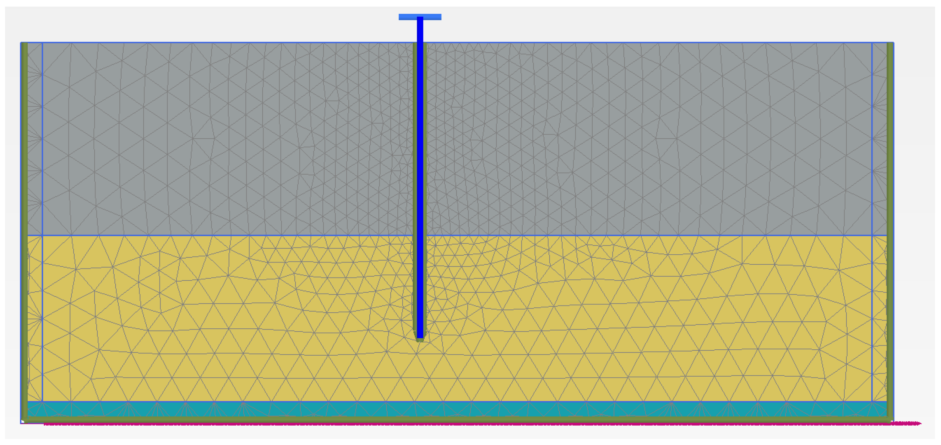
The earthquake records used in the analyses were selected from the scaled Kobe earthquake, and the same earthquake records used in the experiments [13] were used in the numerical model. The earthquake data are presented in Figure 3. In addition, within the scope of the study, the effect of earthquake magnitude was investigated by using earthquake records magnified at different rates. For this purpose, earthquakes were magnified by means of the Plaxis program. Scaled earthquake records are presented in Figure 4 and Figure 5.

3.4. Mesh Analysis

In order to investigate the effect of the mesh density selected in the finite element program on the results, 4 different mesh types were analyzed in a pilot analysis. Finite element programs allow for the use of different types of meshes. Many finite element programs, such as the Plaxis 2D program, recommend using a dense mesh as the results will be more realistic as the mesh density increases. However, as the mesh density increases, the number of elements also increases, and the analysis time increases. In the analyses performed for different element numbers in this study, it is seen that as the mesh density increases, the total deformation decreases and approaches the experimental results, and it would be sufficient to perform the analyses in a very fine mesh range. The numerical model is shown in Figure 6 for the very fine mesh case. The values of the number of elements and the total displacement in the pile cap are presented in Table 5. Additionally, the displacement change according to the number of elements is presented in Figure 7.

3.5. Numerical Verification of the Experiment

A single pile was numerically modeled to verify the experiments performed by Garala et al. [13]. In order to compare the results obtained from numerical modeling, the acceleration values measured along the soil depth in the experiments in the case of single piles were compared with the acceleration values obtained from numerical analyses. A numerical and experimental comparison of peak ground acceleration is presented in Figure 8. The results show that the acceleration change exhibits the same behavior and is largely coherent. Although there are differences between the experimental and numerical results, as an engineering behavior, the maximum acceleration is expected to occur on the surface. In both experimental and numerical results, the maximum acceleration was obtained close to the surface. In addition, although the finite element results largely reflect the general behavior in the comparison, the deviations and consistencies that occur are due to small differences in soil and dynamic loading in the experiment and numerical analysis. Additionally, maximum moment values are compared and presented in Figure 9. It was observed that the results obtained from the numerical analyses performed to compare the maximum moment values were compatible with the experimental results. Certain deviations and consistencies occurred in the bending moment results, similar to the acceleration results. However, from an engineering perspective, it is expected that the maximum bending moment will occur at the layer change between soft clay and dense sand. As expected, the maximum moment value was obtained in the clay–sand transition region, and the compliance at this point was observed to be 94%. In this respect, experimental results and numerical results were obtained in agreement.

4. Parametric Studies

Within the scope of the study, after the experimental data were verified, the effects of different parameters were investigated numerically. In this context, the effects of parameters such as clay layer thickness, groundwater level, pile stiffness, and earthquake magnitude were analyzed. The results obtained from the analyses were evaluated by considering the pile cap displacement and the maximum moment values occurring in the pile.

4.1. Effect of Clay Liner Thickness

In the experimental study, the length of the piles in the clay was 9 m, and the pile length in the sand was 4.8 m. The effect of changing the clay soil layer thickness on the bending moment and pile cap displacement was investigated. For this purpose, the situation in which the pile was completely buried in clay and the clay layer thicknesses of 3, 6, 9, and 12 m were analyzed. In these analyses, groundwater was not considered in the numerical analyses as in the reference experiment. The pile cap displacement change obtained from the analysis is presented in Figure 10, and the maximum moment change curve is presented in Figure 11. Considering the pile cap displacement values, although there was no significant increase in the displacement values initially with the increase in the clay layer thickness, significant increases were observed in the pile cap displacement at the depth where the clay layer thickness reached approximately 75% of the total pile length. No significant increase in displacements was observed as the clay layer thickness reached larger values. This is due to the fact that the pile behaves more flexibly under kinematic conditions, as the number of sockets in the dense sand decreases. When evaluated in terms of bending moments, it is seen that the maximum moment occurs when the clay layer thickness is equal to 75% of the total pile length. It is understood that kinematic conditions increase as the socket length in dense sand reaches a certain level. The reason for the decrease in pile displacement and maximum moment in the case of the socket length being less than this value is that the pile changes to a single-layer behavior and the relative displacements along the pile are minimized.

4.2. Effect of Groundwater Level

In order to investigate the effect of the groundwater level, the condition of the soil being completely clay was investigated numerically. Clay and sand layer thicknesses were not changed in the experimental analysis. For both cases, the groundwater levels at the surface, −3 m, −6 m and −9 m were examined. For both cases, the groundwater level–displacement graph is presented in Figure 12, and the groundwater level–maximum moment graph is presented in Figure 13. Considering the layered soil situation, it is seen that the displacement increases with the increase in the depth of the groundwater level, and there is no significant change in the displacement after the groundwater level reaches −6 m. This situation is caused by the groundwater level approaching the underlying sand layer, and the effect of the groundwater level remaining in the sand on deformation decreases. In the case of only clay, it was observed that the deformation first decreased and then increased as the groundwater level increased. The decrease in the groundwater level causes the upper layer to behave more rigidly and the deformation to decrease up to a certain level. As the water level decreases below the bottom elevation of the pile, the pile behaves flexibly, and its deformation increases. In terms of the maximum moment, in the experimental analysis, if the groundwater is on the surface, the moment takes the lowest value and then shows a very significant change. In the clay case, groundwater does not have a significant effect.

4.3. Effect of Pile Stiffness

In order to investigate the effect of pile stiffness in the analyses, different elasticity moduli were analyzed. For this purpose, the values of the pile elasticity moduli were selected as 17.50, 35, 70, and 140 GPa. Analyses were carried out in layered soil and only-clay soil conditions. The pile displacement–pile stiffness curve obtained from the analysis is presented in Figure 14, and the maximum moment–pile stiffness curve is presented in Figure 15. When the results obtained were examined, it was seen that the deformation decreased with the increase in the elasticity modulus in the layered case, and there was no change in deformation after the elasticity modulus reached the 70 GPa value used in the experiments. When the soil was only clay, it was seen that the deformation increased with the increase in the elasticity modulus, and there was no change in deformation after reaching the value of 70 GPa. In this case, it is understood that the elasticity modulus is effective as it approaches the soil elasticity modulus, and the effect decreases after a certain stiffness. For both cases, moment values increase with the elasticity modulus and approach the asymptote.

4.4. Effect of Earthquake Magnitude

In order to investigate the effect of earthquake magnitude in the study, the earthquake record used in the experiments was enlarged using the Plaxis program, and analyses were carried out at earthquake magnitudes of 0.17 g, 0.34 g, and 0.51 g. The analyses were carried out on the experimental model under stratified soil conditions. The pile cap displacement–acceleration and maximum moment–acceleration graphs obtained from the analysis are presented in Figure 16 and Figure 17, respectively. It is seen that displacements and moments increase linearly with increasing earthquake acceleration. The results obtained show that the earthquake magnitude is the most important parameter affecting the results.

5. Conclusions

In this study, the behavior of piles under dynamic loads was investigated under kinematic conditions. For this purpose, the results of an experimental study in the literature were verified with a finite element program, and the effects of parameters such as soil conditions, groundwater level, pile stiffness, and earthquake magnitude were investigated. The results obtained are summarized below.
  • The results obtained from the centrifuge experiment by Garala et al. [13] were confirmed with numerical analysis results obtained using a finite element program in this study.
  • In the kinematic interaction analyses, with the increase in the weak soil layer thickness in layered soil conditions, although there was no significant increase in the displacement values at first, significant increases were observed in the pile cap displacement at the depth where the clay layer thickness reached approximately 75% of the total pile length. No significant increase in displacements was observed as the clay layer thickness reached larger values. This was due to the fact that the pile behaves more flexible under kinematic conditions as the number of sockets in the dense sand decreased.
  • In the analyses of the investigation of the effect of the groundwater level, considering the stratified situation, it was seen that the displacement increased with the increase in the depth of the groundwater level, and there was no significant change in displacement after the water level reached -6 m. This situation was caused by the groundwater level approaching the underlying sand layer, and the effect of the groundwater level remaining in the sand on deformation decreased.
  • In the only-clay soil, it was observed that as the groundwater level increased, the deformation first decreased, and then the deformation increased. The decrease in the groundwater level caused the upper layer to behave more rigidly and the deformation to decrease up to a certain level. As the water level decreased below the bottom elevation of the pile, the pile behaved flexibly, and its deformation increased.
  • In the analyses examining the effect of pile stiffness, it was observed that deformation decreased as the elasticity modulus increased in the layered case, and there was no change in deformation after the elasticity modulus reached the 70 GPa value used in the experiments. For the only-clay soil, it was seen that the deformation increased with the increase in the elasticity modulus, and there was no change in deformation after reaching the value of 70 GPa. In this case, it is understood that the elasticity modulus was effective as it approached the soil elasticity modulus, and the effect decreased after a certain stiffness.
  • In the analysis examining the earthquake magnitude effect, it was seen that displacements and moments increased linearly with the increase in earthquake acceleration. The results obtained show that the earthquake magnitude is the most important parameter affecting the results.
  • When the results obtained are evaluated from a practical engineering perspective, it is understood that the piles, which are adequate for design under static loads, are exposed to significant bending moments under dynamic loads. Therefore, it is of great importance to take dynamic loads into consideration in the design stage. In addition, under dynamic loads in weak soil conditions, the largest displacement occurs in the pile head, while the highest bending moment occurs in the transition between soil layers. Additional precautions should be taken by increasing the steel reinforcement ratios in the pile foundation connection areas and in the transition between soil layers.
  • Earthquake forces are one of the most important factors that directly affect the design of pile systems. Therefore, using accurate earthquake data is important for design. Selecting earthquake data by taking local soil conditions into consideration will make the design more realistic.

Author Contributions

Conceptualization, project administration, supervision, writing—review and editing, and writing—original draft: S.B.; methodology, data curation, software, validation, and formal analysis: H.T. All authors have read and agreed to the published version of the manuscript.

Funding

This research received no external funding.

Institutional Review Board Statement

Not applicable.

Informed Consent Statement

Not applicable.

Data Availability Statement

Not applicable.

Acknowledgments

The authors would like to thank Thejesh Kumar Garala, Gopal S.P. Madabhushi, and Raffaele Di Laora for the experimental data supporting the article.

Conflicts of Interest

The authors declare no conflict of interest.

References

  1. Mizuno, H. Pile damage during earthquakes in Japan. Dyn. Response Pile Found. 1987, 53–78. [Google Scholar]
  2. Gazetas, G.; Tazoh, T.; Shimizu, K.; Fan, K. Seismic response of the pile foundation of Ohba-Ohashi bridge. In Proceedings of the 3rd Conference of the International Conference on Case Histories in Geotechnical Engineering, St. Louis, MO, USA, 1–9 June 1993. [Google Scholar]
  3. Kaynia, A.M. Dynamic Stiffness and Seismic Response of Pile Groups. Ph.D. Dissertation, Massachusetts Institute of Technology, Cambridge, MA, USA, 1982. [Google Scholar]
  4. Fan, K.; Gazetas, G.; Kaynia, A.; Kausel, E.; Ahmad, S. Kinematic seismic response of single piles and pile groups. J. Geotech. Eng. 1991, 117, 1860–1879. [Google Scholar] [CrossRef]
  5. Kavvads, M.; Gazetas, G. Kinematic seismic response and bending of free-head piles in layered soil. Geotechnique 1993, 43, 207–222. [Google Scholar] [CrossRef]
  6. Haigh, S.K. Effects of Earthquake-Induced Liquefaction on Pile Foundations in Sloping Ground. Doctoral Dissertation, University of Cambridge, Cambridge, UK, 2002. [Google Scholar]
  7. Brandenberg, S.J.; Boulanger, R.W.; Kutter, B.L.; Chang, D. Behavior of pile foundations in laterally spreading ground during centrifuge tests. J. Geotech. Geoenviron. Eng. 2005, 131, 1378–1391. [Google Scholar] [CrossRef]
  8. Castelli, F.; Maugeri, M.; Mylonakis, G. Numerical analysis of kinematic soil—Pile interaction. In Proceedings of the AIP Conference Proceedings, American Institute of Physics, Reggio Calabria, Italy, 8–11 July 2008; Volume 1020, pp. 618–625. [Google Scholar]
  9. Madabhushi, G.; Haigh, S.; Knappett, J. Design of Pile Foundations in Liquefiable Soils; World Scientific: Singapore, 2009. [Google Scholar]
  10. Haskell, J.J.M. Guidance for the Design of Pile Groups in Laterally Spreading Soil. Doctoral Dissertation, University of Cambridge, Cambridge, UK, 2014. [Google Scholar]
  11. Luo, X.; Li, S.; Xu, H. Results of real-time kinematic positioning based on real GPS L5 data. IEEE Geosci. Remote Sens. Lett. 2016, 13, 1193–1197. [Google Scholar] [CrossRef]
  12. Mallick, M.; Mandal, K.K.; Sahu, R.B. Effects of axial loading on dynamic response of laterally loaded single piles in liquefiable layered soil of Kolkata city considering nonlinearity of soil. SN Appl. Sci. 2022, 4, 297. [Google Scholar] [CrossRef]
  13. Garala, T.K.; Madabhushi, G.S.; Di Laora, R. Experimental investigation of kinematic pile bending in layered soils using dynamic centrifuge modelling. Géotechnique 2022, 72, 146–161. [Google Scholar] [CrossRef]
  14. Garala, T.K.; Madabhushi, G.S. Comparison of seismic behaviour of pile foundations in two different soft clay profiles. In Physical Modelling in Geotechnics; CRC Press: Boca Raton, FL, USA, 2018; Volume 2, pp. 1359–1364. [Google Scholar]
  15. Sahare, A.; Ueda, K.; Uzuoka, R. Influence of the sloping ground conditions and the subsequent shaking events on the pile group response subjected to kinematic interactions for a liquefiable sloping ground. Soil Dyn. Earthq. Eng. 2022, 152, 107036. [Google Scholar] [CrossRef]
  16. Yamashita, K.; Shigeno, Y.; Hamada, J.; Chang, D.W. Seismic response analysis of piled raft with grid-form deep mixing walls under strong earthquakes with performance-based design concerns. Soils Found. 2018, 58, 65–84. [Google Scholar] [CrossRef]
  17. Kaynia, A.M. Effect of kinematic interaction on seismic response of offshore wind turbines on monopiles. Earthq. Engng. Struct. Dyn. 2021, 50, 777–790. [Google Scholar] [CrossRef]
  18. Al-Jeznawi, D.; Jais, I.B.M.; Albusoda, B.S.; Khalid, N. Numerical modeling of single closed and open-ended pipe pile embedded in dry soil layers under coupled static and dynamic loadings. J. Mech. Behav. Mater. 2022, 31, 587–594. [Google Scholar] [CrossRef]
  19. Hu, H.; Gan, G.; Bao, Y.; Guo, X.; Xiong, M.; Han, X.; Chen Cui, L.; Wang, L. Nonlinear stochastic seismic response analysis of three-dimensional reinforced concrete piles. Buildings 2023, 13, 89. [Google Scholar] [CrossRef]
  20. Huang, W.; Liu, J.; Wang, H.; Ayasrah, M.; Qiu, H.; Wang, Z. Study on dynamic response of inclined pile group foundation under earthquake action. Buildings 2023, 13, 2416. [Google Scholar] [CrossRef]
  21. Tipsunavee, T.; Arangjelovski, G.; Jongpradist, P. Numerical analysis on effects of soil improvement on pile forces on existing high-rise building. Buildings 2023, 13, 1523. [Google Scholar] [CrossRef]
  22. FEMA. NEHRP, Prestandard and Commentary for the Seismic Rehabilitation of Buildings (No. 356); Report; FEMA: Washington, DC, USA, 2000.
  23. American Association of State Highway Transportation Officials (AASHTO). Guide Specifications for Seismic Isolation Design; American Association of State Highway Transportation Officials (AASHTO): Washington, DC, USA, 1999. [Google Scholar]
  24. European Committee for Standardization. EC8 Eurocode 8 (EN 1998-1, EN 1998-5): Seismic Design of Building; European Committee for Standardization: Bruxelles, Belgium, 2004. [Google Scholar]
  25. Turkish Building and Earthquake Regulation (TBDY). 2018.
  26. ASTM D854; Standard Test Methods for Specific Gravity of Soil Solids by Water Pycnometer. ASTM International: West Conshohocken, PA, USA, 2014.
  27. ASTM D4254; Standard Test Methods for Minimum Index Density and Unit Weight of Soils and Calculation of Relative Density. ASTM International: West Conshohocken, PA, USA, 2016.
  28. ASTM D4253; Standard Test Methods for Maximum Index Density and Unit Weight of Soils Using a Vibratory Table. ASTM International: West Conshohocken, PA, USA, 2016.
  29. ASTM D6913; Standard Test Methods for Particle-Size Distribution (Gradation) of Soils Using Sieve Analysis. ASTM International: West Conshohocken, PA, USA, 2017.
  30. ASTM D7181; Standard Method for Consolidated Drained Triaxial Compression Test for Soils. ASTM International: West Conshohocken, PA, USA, 2011.
  31. Kok, S.; Huat, B.B. Numerical Modeling of Laterally Loaded Piles. Am. J. Appl. Sci. 2008, 5, 1403–1408. [Google Scholar] [CrossRef]
  32. Van der Kwaak, B. Modelling of Dynamic Pile Behaviour during an Earthquake Using PLAXIS 2D: Embedded Beam (Row). Master’s Thesis, Delf University of Technology, Delft, The Netherlands, 2015. [Google Scholar]
  33. Rathod, D.; Muthukkumaran, K.; Sitraham, T.G. Dynamic response of single pile located in soft clay underlay by sand. Int. J. Geomate 2016, 11, 2563–2567. [Google Scholar] [CrossRef]
  34. Kardogan, P.S.O.; Stacul, S.; Pagnini, F.; Squeglia, N.; Bhattacharya, S. 2D FEM Analyses for the Evaluation of Seismic Performance of Single Pile and Pile Group-Supported Structure in Liquefiable Soil; Associazione Geotecnica Italiana: Rome, Italy, 2019; ISBN 978-0-367-14328-2. [Google Scholar]
  35. Deendayal, R. Finite element analysis of a single pile under cyclic loading. Int. J. Civ. Eng. Technol. IJCIET 2017, 8, 918–924. [Google Scholar]
  36. Deendayal, R.; Nigitha, D. Response of single pile under dynamic loading. In Proceedings of the Indian Geotechnical Conference 2017 GeoNEst, Guwahati, India, 14–16 December 2017. [Google Scholar]
  37. Plaxis 2D Reference Manual; PLAXIS B.V.: Delft, The Netherlands, 2023.
  38. Hardin, B.O.; Drnevich, V.P. Shear modulus and damping in soils: Design equations and curves. J. Soil Mech. Found. Div. 1972, 98, 667–692. [Google Scholar] [CrossRef]
  39. Snyder, J.L. Full Scale Test Lateral Load Tests of a 3 × 5 Pile Group in Soft Clays and Silts. Master’s Thesis, Brigham Young University, Provo, UT, USA, 2004. [Google Scholar]
  40. Lau, B.H. Cyclic Behaviour of Monopile Foundations for Offshore Wind Turbines in Clay. Ph.D. Dissertation, University of Cambridge, Cambridge, UK, 2015. [Google Scholar]
  41. Brinkgreve RB, J.; Engin, E.; Engin, H.K. Validation of empirical formulas to derive model parameters for sands. Numer. Methods Geotech. Eng. 2010, 1, 137–142. [Google Scholar]
  42. Phoban, H.; Seeboonruang, U.; Lueprasert, P. Numerical modeling of single pile behaviors due to groundwater level rising. Appl. Sci. 2021, 11, 5782. [Google Scholar] [CrossRef]
Figure 1. Schematic view of experimental set-up [13].
Applsci 13 11653 g001
Figure 2. Numerical model of the experiment of Garala et al. [13].
Applsci 13 11653 g002
Figure 3. Acceleration–time curves for 0.085 g.
Applsci 13 11653 g003
Figure 4. Acceleration–time curves for 0.17 g.
Applsci 13 11653 g004
Figure 5. Acceleration–time curves for 0.51 g.
Applsci 13 11653 g005
Figure 6. Numerical model for very fine mesh case.
Applsci 13 11653 g006
Figure 7. Number of element–pile cap displacement curves.
Applsci 13 11653 g007
Figure 8. Numerical and experimental comparison of peak accelerations.
Applsci 13 11653 g008
Figure 9. Numerical and experimental comparison of maximum moments.
Applsci 13 11653 g009
Figure 10. Pile cap displacement–clay layer thickness curves.
Applsci 13 11653 g010
Figure 11. Maximum moment–clay layer thickness curves.
Applsci 13 11653 g011
Figure 12. Pile cap displacement–groundwater level curves.
Applsci 13 11653 g012
Figure 13. Maximum moment–groundwater level curves.
Applsci 13 11653 g013
Figure 14. Pile cap displacement–pile stiffness curves.
Applsci 13 11653 g014
Figure 15. Maximum moment–pile stiffness curves.
Applsci 13 11653 g015
Figure 16. Pile cap displacement–acceleration curves.
Applsci 13 11653 g016
Figure 17. Maximum moment–acceleration curves.
Applsci 13 11653 g017
Table 1. Parameters of sand soil used in the experiments [13].
PropertyStandardValue
Specific gravity, GsASTM D854 [26]2.65
Maximum void ratio, emaxASTM D4254 [27]0.767
Minimum void ratio, eminASTM D4253 [28]0.49
Effective particle size, D10 (mm)ASTM D6913 [29]0.68
Average particle size, D50 (mm)ASTM D6913 [29]0.80
Coefficient of uniformity, CuASTM D6913 [29]1.221
Coefficient of curvature, CcASTM D6913 [29]0.97
Relative density, Dr (%)ASTM D4254 [27]85
Peak friction angle, ϕp (°)ASTM D7181 [30]37.2
Table 2. Properties of Speswhite kaolin clay [11].
PropertyValue
Plastic limit, PL (%)30
Liquid limit, LL (%)63
Plasticity index, PI (%)33
Specific gravity, Gs2.60
Slope of critical state line (CSL) in q-p′ plane0.90
Slope of an unload-reload line, (κ)0.039
Intercept of CSL at p′ = 1 kPa (Γ)3.31
Slope of normal consolidation line (λ)0.22
Table 3. Hardening soil small parameters for numerical analysis.
ParametersUnitSpeswhite Kaolin ClayLeighton Buzzard SandLE
Material type-HS SmallHS SmallLinear Elastic
Drainage type-UndrainedDrainedDrained
γunsat, Unsaturated unit weightkN/m316.218.424.00
γsat, Saturated unit weightkN/m316.420.3624.00
einit, initial void ratio-0.500.500.50
Rayleigh, α-0.094250.094250.00
Rayleigh, β-7.958 × 10−47.96 × 10−40.00
ν′, Poisson’s ratio (linear elastic)---0.20
G′, Shear moduluskN/m2--1.04 × 107
E′, Elasticity moduluskN/m2--2.50 × 107
Vs, S wave velocitym/s--2063.00
Vp, P wave velocitym/s--3370.00
E50ref, Secant stiffnesskN/m215005.10 × 104
Eoedref, Tangent stiffnesskN/m27505.10 × 104
Eurref, Unloading/reloading stiffnesskN/m280001.5 × 105
m, Rate of stress-dependency-0.80.4344
c′, CohesionkN/m210.00
Ø, Internal friction angle°2137.20
Ψ, dilatation angle°08.625
γ0.7, Shear strain at 0.7G0-2.00 × 10−41.15 × 10−4
G0ref, Small strain stiffnesskN/m21.398 × 1041.178 × 105
ν′ur, Poisson’s ratio-0.200.20
Pref, Reference stresskN/m2100.00100.00
K0nc, Stress ratio-0.640.3954
Rinter, Interface factor-0.500.70
Table 4. The properties of pile and pile caps for numerical analysis.
ParameterUnitPile CapPile
Material type-ElasticElastic
EA1kN/m9.90 × 1059.30 × 106
EA2kN/m9.90 × 1059.930 × 106
EIkN/m2/m74253.439 × 105
dm0.30.6661
wkN/m/m3.52.8
ν-0.370.3
Rayleigh α-0.28270.2827
Rayleigh β-2.39 × 10−32.39 × 10−3
Table 5. Number of element-pile cap displacement values.
Mesh TypeNumber of ElementPile Cap Displacement (m)
Coarse8820.021
Medium10930.022
Fine16870.018
Very Fine22070.018
Disclaimer/Publisher’s Note: The statements, opinions and data contained in all publications are solely those of the individual author(s) and contributor(s) and not of MDPI and/or the editor(s). MDPI and/or the editor(s) disclaim responsibility for any injury to people or property resulting from any ideas, methods, instructions or products referred to in the content.

