Article

Control Strategies for Piston Trajectory in Ionic Compressors for Hydrogen Storage

1
School of Energy and Power Engineering, Xi’an Jiaotong University, Xi’an 710049, China
2
Shanghai Marine Diesel Engine Research Institute, Shanghai 201108, China
*
Author to whom correspondence should be addressed.
Appl. Sci. 2023, 13(21), 11759; https://doi.org/10.3390/app132111759
Submission received: 15 September 2023 / Revised: 25 October 2023 / Accepted: 26 October 2023 / Published: 27 October 2023

Abstract

:
The ionic compressor is a new and prospective technology applied for hydrogen storage which adopts a hydraulic system in which the hydraulic drive unit is a solid piston in the compression cavity. Controlling the trajectory of the solid piston is critical for achieving the designed thermodynamic process of compression. However, a strategy for controlling the position of a piston in an ionic compressor has not been reported in the open literature. In this paper, three valve-controlled methodologies are proposed for the effective control of a piston’s trajectory in an ionic compressor. A transient numerical model of the entire compression system was built using AMESim 2021 software. The performances of the proposed control methods were simulated and compared. The results show that the maximum isothermal efficiency, 50.28%, was obtained in the system using Position-P control, for which the highest hydrogen discharge mass for a single compression cycle of 1.14 g, a relatively low specific energy consumption of 2395.17 J/g, and a relatively small velocity control error of 0.32 m/s were observed. Although the lowest specific energy consumption was found in the case of the Dual-PS control method, the smallest mass product was also found for this case. Therefore, the Position-S control strategy was identified as the optimal method for a hydraulically driven ionic liquid compressor system.

1. Introduction

Fossil fuels are well known as the source of main energy for countries around the world, providing important support for economic, scientific, technological, and cultural development and progress [1]. The combustion of fossil fuels produces greenhouse gases [2], such as carbon dioxide, which contribute to the increase in global temperatures and increase the number of extreme climate events [3]. To solve environmental problems and achieve sustainable and renewable energy development, the transformation of traditional energy systems is essential [4].
Hydrogen is a prospective solution to solving these environmental issues and achieving sustainable development due to the high amount of energy provided per mass and the clean-burning nature of the product [5]. Hydrogen can be used as fuel in many fields such as power generation and transportation [6]. With the development of the new energy automobile industry, the promotion of hydrogen fuel cell vehicles has become one of the important means of reducing greenhouse gas emissions in the automobile industry [7]. Due to the low energy density of hydrogen at atmospheric pressure [8], its direct application in fuel-cell vehicles may require the vehicle to be refueled frequently or have a larger storage space, ultimately increasing costs [9]. Expanding the storage pressure of hydrogen by compressing it is an effective solution for increasing its volumetric energy density [10]. Commonly utilized technologies for compressing hydrogen consist of reciprocating piston compressors [11], diaphragm compressors, linear compressors, metal hydride compressors [12], and ionic liquid compressors [13].
In recent years, researchers have paid significant attention to the impressive performance of ionic compressors. A compressor utilizing an ionic liquid operates based on a hydraulic drive system that propels the solid piston back and forth. This motion leads to the compression of the gas by the piston of the ionic liquid located on the solid piston [14]. Ionic liquids possess virtually incompressible properties, low vapor pressures [15], high degrees of stability [16], and good lubrication and cooling properties [17]. Moreover, hydraulic drive systems exhibit advantages such as rapid responses, high rigidity, and high load capacities [18]. By utilizing ionic liquid piston technology, ionic liquid compressors achieve superior volumetric and isentropic efficiencies compared to conventional compressors [19]. Additionally, the integration of hydraulically driven free-piston technology substantially reduces the number of moving parts in the compressor and allows for controlled piston trajectories [20]. The synergistic integration of these two technologies endows ionic compressors with remarkable adaptability to achieve efficient compression processes across a broad spectrum of operating conditions. While ionic liquid compressors offer numerous advantages, the use of free pistons places high demands on the design and control of hydraulic systems [21].
In an ionic compressor, the motion of the metal piston impacts the dynamic property of the ionic liquid and consequently affects the behavior of the two-phase gas–liquid flow. This has a significant influence on the performance of the compressor. Additionally, compressor breakdown is a leading cause of downtime at hydrogenation stations, accounting for 30% of the total maintenance time [22]. Ionic liquid compressors are driven by hydraulic systems, which are free of rigid connections such as crank connecting rods. Therefore, there is no piston crash caused by a rigid connection in these compressors. Piston crashes can result in damage to the piston, cylinder, valves, and other critical components. Therefore, it is imperative to employ specific control techniques for regulating the motion of the free piston in an ion compressor. Controlling the flow of the hydraulic oil inlet and the outlet of the hydraulic cylinder can achieve the purpose of controlling the movement speed of the free piston, which not only allows the piston to move according to a specific trajectory but also greatly reduces the probability of the piston colliding with the cylinder and the subsequent hazards.
Several studies have shown that the piston’s trajectory is a crucial factor in determining the performance of the designed machine. Zhang et al. [23] analyzed and simulated an HCCI combustion process of ammonia. The results showed that the most effective piston trajectory for the HCCI combustion of ammonia was the symmetric trajectory, the thermal efficiency of which was about 58.1%. Silva et al. [24] obtained the optimal motion curve of a piston via simulations based on the proposed model, considering variations in the energy and mass conservations of the reciprocating compressor. Wei et al. [25] designed a new type of two-piston linear compressor for which findings indicate that the highest performance was observed when the system operated following a triangular trajectory. Numerous studies, as mentioned above, demonstrate that the free piston’s trajectory has a significant influence on the system’s performance.
The hydraulic drive system provides the possibility of flexibly regulating the movement of the solid piston of an ionic compressor [26]. Hydraulic drive systems are widely used in various industries and have been studied by many researchers for achieving high levels of control accuracy and low levels of energy consumption. Zhu et al. [27] improved the response performance of a free piston in a proposed counter-rotating engine using a combination of the Gray mode-modified energy equation feedforward and PID control. Helian et al. [28] experimentally verified that high tracking accuracy was achieved using the proposed nonlinear motion control method in the case of the large dynamic nonlinearity of the hydraulic system. Zhu et al. [29] proposed an adaptive controller for hydraulic drive units, combining the state observation of the polynomial nonlinear extension and a linearization control method based on the adaptive feedback signal, which improved the performance of the impedance control in the hydraulic system. Yan et al. [30] proposed a control method to increase the energy efficiency of a hydraulic system by addressing the mismatch issue between the desired and designed power supplies based on a waterjet cutting machine. Chen et al. [31] proposed a control strategy for the cylinder’s position based on valves through the adaptive backsliding solution, which enhanced the accuracy and anti-interference ability of the hydraulic loading system.
However, a study on the piston trajectory control of ionic compressors is not reported in the open literature. Therefore, the novelty of this study is (I) to propose three control strategies for the piston’s trajectory in an ionic liquid compressor, (II) to investigate the compressor’s performance using transient numerical modeling, and (III) to obtain an optimal control strategy by comparing the performances of different control strategies. The research method and the results of this paper provide a reference for the design and operation of ionic compressors.

2. Methodology and Numerical Model

This paper simulated and analyzed an ionic liquid compressor system using AMESim software, which allows for the bi-directional transfer of data for each component, thus providing the advantage of high simulation accuracy and graphical modeling [32]. It aims to provide an effective hydraulic system for an ionic compressor. System simulations were carried out based on the assumptions listed below.
(1)
The system operation is considered an adiabatic process for design purposes;
(2)
The impact of ionic liquid fluctuations on the thermodynamic process is ignored;
(3)
The effects of the physical properties of the ionic liquids are neglected.

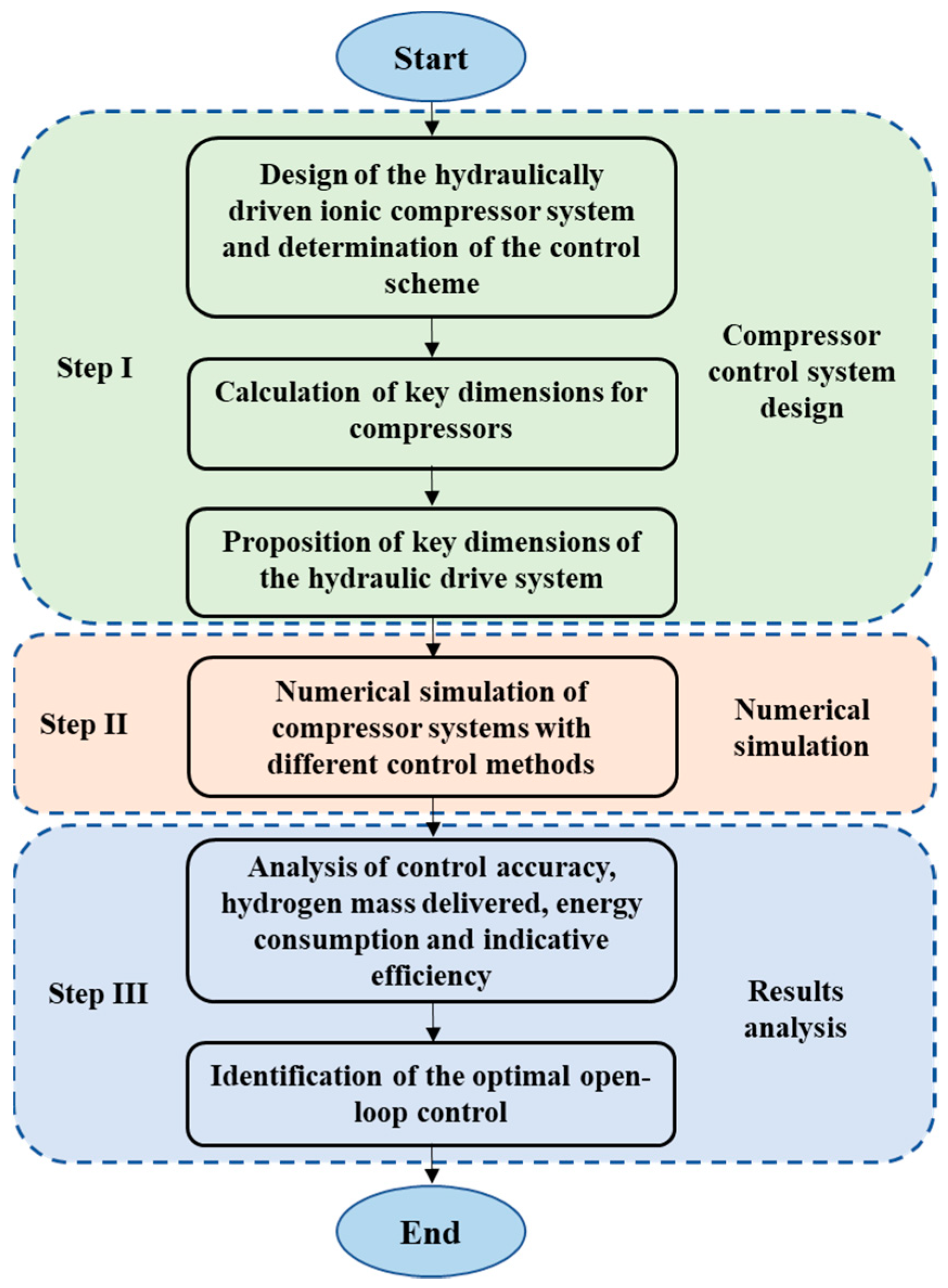
2.1. Research Methodology

In this paper, the design and research methodology of a piston speed control strategy for a hydrogen compressor based on valve control is shown in Figure 1. The entire research process can be divided into three phases: system design and calculation, numerical simulation, and an analysis of the results. The functional design of the hydraulically driven ionic compressor system and the proposition of the control scheme were carried out first in order to realize the speed control function of the hydraulic system and the gas compression function of the compressor. The structure of the compressor system is presented in Figure 2 and mainly comprises a gas valve, piston, gas compression cavity, electromagnetic directional valve, motor, pump, hydraulic cylinder, relief valve, and speed control component. An isolation chamber was designed in the compressor between the ionic liquid and the hydraulic oil. The leakage of either the ionic liquid or the hydraulic oil can be removed through the leakage channel when the piston moves down, connecting the isolation chamber and the leakage channel. A gas–liquid separator is required after the compressor as some ionic liquid droplets may be discharged with the hydrogen gas from the compressor.
The speed control component is composed of a constant-differential-pressure-reducing valve and a throttle valve. The mass flow of the throttle valve can be controlled by changing the throttle valve opening as a constant difference between the pressure values at the two ends of the throttle valve can be guaranteed via the constant-differential-pressure-reducing valve. The piston trajectory is controlled by adjusting the flow of hydraulic oil in and out of the oil cylinder, using a speed component valve. Three control strategies, Position-P control, Position-S control, and Dual-PS control, are proposed in this paper, as shown in Figure 3. In Position-P control, the flow rate is regulated by adjusting the valve opening of the speed control element located at the inlet of the oil cylinder to match the hydraulic fluid flow to the flow rate required for the desired speed of movement of the piston. Position-S control regulates the piston speed by controlling the flow leaving the hydraulic cylinder through a speed-control component, which is similar in principle to Position-P control. Dual-PS control is the combination of Position-P control and Position-S control to achieve greater control accuracy. The results of the different control methods were obtained and compared using simulations.
After finalizing the design of the structure of the compressor system, critical dimensions for the cylinders, pistons, valves, hydraulic cylinders, pumps, and hydraulic valves were determined based on the design requirements, as shown in Table 1. The designed inlet pressure was 12 MPa, which is an average value for the hydrogen production pressure [33], while the designed outlet pressure was 45 MPa, which is a typical value for hydrogen storage [34]. This means that pressure elevation is achieved through one-stage compression, with a pressure ratio of 3.75. The piston velocity equation used in the simulation is provided in Table 1 [35]. The operating frequency of the piston was 5.0 Hz, and the motion velocity profile was set as a sinusoidal function. Additionally, the hydrogen flow rate was 200 Nm3/h, with an inlet temperature of 25 °C. After the key dimensions were obtained, a corresponding numerical simulation model of the entire system was established using AMESim. A numerical simulation was then conducted with the three control strategies. The results of an analysis of the control error, the internal energy produced, and the hydrogen mass delivered under the different control methods were obtained, based on which the optimal control approach for the entire system was identified.

2.2. Numerical Model

The entire numerical simulation model can be divided into a hydraulic drive system and a hydrogen compression system in which the key dimensions of components such as cylinders, pistons, hydraulic cylinders, valves, hydraulic valves, and pumps are the basis of the numerical simulation. The numerical model of the hydraulically driven hydrogen compressor system utilizing the Dual-PS control method built in AMESim is provided in Figure 4. The hydrogen compression subsystem was numerically modeled using components in the pneumatic library, pneumatic component design library and signal control library. It predominantly comprises pre-defined components including cylinders, pistons, pressure gauges, valves, gas sources, and signal sources. The van der Waals equation of state for the submodel in the pneumatic library in AMESim was used in the simulations to account for variations in behavior due to the non-ideal nature of the hydrogen gas.
The hydrogen compression subsystem contains a cylinder, piston, valve, and pressure gauge. In the simulation, the pressure gauge measures the cylinder’s internal pressure. If the pressure inside the cylinder drops below 12 MPa, the inlet valve receives an open signal, and hydrogen gas is introduced into the cylinder. Conversely, when the pressure inside the cylinder exceeds 45 MPa, the exhaust valve is signaled to open, and the compressed gas is released from the cylinder.
The key geometrical dimensions of the hydrogen compression system are the diameter of the compression cavity D , the stroke s , and the valve area for fluid A e , which can be determined by Equations (1)–(3), respectively.
D = 4 V s t 60 π r f 3
s = D r
A e = A p N v v m v m
The stroke volume V s t is calculated using Equation (4), while the average flow rate v v m can be determined using Equation (5).
V s t = F i n λ d
v v m = M a
where F i n is the hydrogen inlet flow rate, determined using Equation (6); λ d is the delivery coefficient, which can be obtained using Equation (7); M is the average Mach number of the valve gap; and a is the speed of sound.
F i n = F 0 60 × p 0 p i n × T i n T 0
λ d = λ V λ p λ T λ l
λ V = 1 r C V ( ε c 1 k c 1 )
where p is the pressure; T is the temperature; 0 and in denote standard and inlet conditions, respectively; λ V is the volume coefficient; λ p , λ T , and λ l are the pressure, temperature, and leakage coefficients, respectively; r C V is the ratio of clearance volume; ε c is compression ratio; and k c is the process coefficient of expansion.
According to the design specifications of the ionic compressor, the necessary dimensions for the hydrogen compression model can be calculated using the equations provided above. Both the cylinder diameter and solid piston stroke were obtained as 0.055 m, while both the effective diameter of the inlet and discharge valves were calculated to be 0.004 m.
A hydraulic drive subsystem was adopted to achieve hydrogen compression and piston trajectory control, as illustrated in Figure 4. In this subsystem, the model primarily employs a mechanical library, a hydraulic library, a hydraulic component design library, and a signal control library. The key predefined components used consist of hydraulic cylinders, pistons, directional valves, speed control valves, tanks, control signals, motors, and pumps. During the simulation, the electromagnetic reversing valve establishes the oil inlet and outlet positions of the oil cylinder, while the speed control component regulates the oil flow. The operating position of the electromagnetic directional valve and the valve opening size of the speed control component can then be controlled by adjusting the electrical signal, leading to the realization of the designed piston trajectory.
The hydraulic cylinder was designed as a single-piston rod unit with a relief pressure of 31.5 MPa for the relief valve. As can be seen from the structure sketch of the compressor system, the cylinder piston’s rod diameter D 1 is equal to the cylinder piston’s diameter D . The hydraulic cylinder piston’s diameter D 2 can be calculated by Equation (9).
0.7 D 2 = D 1
The pump speed n and pump displacement V d determine the flow of hydraulic fluid into the hydraulic system. The pump displacement V d is obtained using Equation (10).
V d = Q n m
where Q represents the theoretical flow rate transferring in, which can be calculated using Equations (11) and (12); and n m is the motor speed, which is 1500 r/min in this design.
Q = v m a x × π D 2 2 4
v m a x = s 2 2 π f
The speed control valve comprises a constant differential pressure reduction valve and a throttle valve. The size of the valve opening can be regulated to control the flow of hydraulic oil entering and exiting due to a constant pressure difference across the throttle valve. In this study, the constant differential pressure reduction valve maintains a pressure difference of 0.8 MPa across both ends of the throttle valve. The maximum opening hydraulic diameter of the throttle valve can be calculated using Equations (13) and (14).
A r = Q C q 2 ρ p
D h = 4 A r π
where A r is the maximum cross-sectional area of the flow; C q is the flow coefficient; p is the throttle inlet and outlet differential pressure, which is the set value of the uniform-pressure-drop valve; and ρ is the density of hydraulic oil.
Based on Equations (9)–(14), the key dimensions of the numerical model were then obtained and are summarized in Table 2.
The pressure of the hydraulic fluid is calculated using Equation (15), considering the compressibility of the hydraulic fluid.
d p d t = β d ρ ρ d t
where β is the bulk modulus of the hydraulic fluid; and d ρ d t is the differential of the density of the hydraulic fluid, which can be calculated using Equation (16).
d ρ d t = 1 V d m d t m V 2 d V d t
where V and m are the volume and mass of the hydraulic fluid, respectively.
The energy conservation during the compressor operation is shown in Equation (17) [36].
d Q d t = d U d t + d W d t
where p is the gas pressure in the hydrogen compression chamber; V is the volume of the compression chamber; n is the number of moles of the gas; R is the gas constant; Q is the heat exchange energy; U is the thermodynamic energy; and W is the external output power.
The hydrogen compression system interacts with the hydraulic drive system through the piston, as illustrated in Figure 5. The corresponding mechanical model is defined using Equation (18).
F g + M g + F h 2 F h 1 F f = M a
where F g is the gas force in the cylinder, which can be calculated using Equation (19); M is the mass of the piston; g is the acceleration of gravity; F h 1 and F h 2 are the hydraulic oil forces, which can be calculated using Equations (20) and (21); F f is the friction force on the piston; and a is the acceleration of the piston, which can be calculated using Equation (22).
F g = π D 2 4 p g
F h 1 = π D 2 2 4 p h 1
F h 2 = π ( D 2 2 D 1 2 ) 4 p h 2
a = d v d t
where, p g is the pressure of the gas; p h 1 is the oil pressure at the bottom surface; p h 2 is the oil pressure at the surface with the piston rod; and v is the solid piston’s speed.
The isothermal efficiency η i s is an essential parameter for evaluating the performance of the compressor, and it can be calculated using Equation (19).
η i s = W i s W i n p
where W i s is the energy consumption of the isothermal compression process, calculated using Equation (24); and W i n p is the energy input.
W = V d p
Considering the design objectives, transient numerical simulations of the hydrogen compression process of the ionic liquid compressor system were performed using the AMESim software. Ten consecutive compression cycles of the compressor were numerically simulated in the study to achieve the steady cyclic operation of the compressor. The initial temperature and pressure in the compression chamber were set at 25 °C and 12 MPa, respectively. In addition, the initial position of the free piston was set at the bottom, dead center, which was 0.055 m.

3. Results and Discussions

3.1. Results of Control Errors under Different Control Methods

In order to obtain an optimal valve-controlled ionic compressor system with better performance, three control methods, Position-P control, Position-S control, and Dual-PS control, are compared in this paper. In this study, ten consecutive numerical simulations of the hydrogen compression cycle process were performed to ensure that the compressor reaches stable operation. The free piston of the ionic compressor is designed to move along a symmetric sinusoidal trajectory by means of speed control. The displacement curves of the free piston under different control methods are shown in Figure 6. It shows that the results were stabilized from the third cycle of operation. When the compressor undergoes expansion and suction, the displacement curve of the free piston controlled using Position-P control was found to be a straight line which deviated from the sinusoidal trajectory. However, the trajectory of the free piston controlled via Position-S control and Dual-PS control matched the sinusoidal trajectory. All three methods showed effective control in the compression and discharge processes as the piston trajectories aligned well with the sinusoidal trajectories. Although the maximum displacement of the free piston with the Position-P method was found to be the same as in the other two cases, a crash of the piston was found in this case. The displacement of the free piston at the bottom center position was found to be 6.64 × 10⁻⁴ m and 6.77 × 10⁻⁴ m when the system was controlled using the Position-P and Dual-PS methods, respectively.
This study aimed to regulate the speed and trajectory of the piston by managing the flow rate in and out of the hydraulic cylinder via a speed control valve assembly. Figure 7 depicts the flow rate of the hydraulic oil into and out of the cylinders with the three control methods during the sixth compression cycle. The hydraulic cylinder oil inlet curve showed a sinusoidal feature when the Position-P method was adopted, which was consistent with the design objective. However, in a time of 1.1–1.2 s, the hydraulic cylinder oil discharge of the Position-P control system increased rapidly and then stabilized at 250 L/min with the Position-P control method, which was inconsistent with the design. This was because the pressure of the hydraulic oil at its discharge port could not be quickly adjusted with the change in the gas compression chamber as the oil discharge port was directly connected to the oil tank through the reversing valve. Fluctuations in the oil flow rates at the inlet and outlet of the hydraulic cylinder were observed at around 1.0 and 1.1 s in all simulations with different control methods. These fluctuations were caused by the sudden change in the direction of the flow of hydraulic oil at 1.0 and 1.1 s due to the variation in the connecting location of the electromagnetic valve.
Figure 8 shows the variation in the piston’s motion speed with time for the three control methods. In comparing the speed curves of the various control methods with the set speed curves, it was evident that the sudden reversal of the direction due to the change in the electromagnetic valve caused the piston’s speed to fluctuate to a certain extent due to hydraulic shock during reversal. The piston’s speed was found to rise rapidly to 0.84 m/s and remained constant when the compressor entered the expansion and suction phases when the Position-P control method was used. This indicates a failure in the control of the piston’s speed during the gas expansion and suction processes. Fluctuations in the velocity were found when the velocity was around 0 m/s. This is because when the connecting location of the reversing valve abruptly changed, the motion state of the hydraulic fluid in the connected piping underwent a significant alteration, causing a hydraulic shock. It can be seen that the most intensive hydraulic shock was found in the system utilizing the Position-S control method.
Control error is an important parameter that indicates the control accuracy of a control system. The variation in the control error with time under different control methods and the maximum error in the case of the simulation results’ stabilization are shown in Figure 9. It can be seen that the largest control deviation and the lowest control accuracy were obtained when using the Position-P control method because it failed to achieve the control effect during the expansion and suction processes. The commutation hydraulic shock was dependent on the pipe diameter of the system, with the optimal diameter varying between systems. The pipe diameters were identical in this design. To accurately compare errors resulting from the control method, it was necessary to disregard any deviation caused by hydraulic shock during commutation. For all three control methods, the maximum control errors appeared at the position at which the maximum free piston velocity was reached. The maximum positive errors of the Position-P, Position-S, and Dual-PS control methods obtained were 0.68, 0.32, and 0.11 m/s, respectively. The maximum negative errors obtained when utilizing the Position-P, Position-S and Dual-PS control methods were −0.60, 0.12, and −0.08 m/s, respectively.

3.2. Energy Consumption and Isothermal Efficiency Results When Using Different Control Methods

A p - V diagram of the compressor, comparing the different control methods, is provided in Figure 10. It can be seen directly that the expansion of the gas finished the earliest in the system utilizing the Position-S control method, while the latest was observed in the case with the Dual-PS control method. This was because the bottom center position of the piston was reached the earliest with the Position-S control method, while it was achieved the latest when the Dual-PS method was used, as presented in Figure 6. It was found that the smallest stroke volume of the compressor was 1.28 × 102 cm3 in the system using the Position-S control method, while in the cases using the Position-P or Dual-PS methods, it was found to be around 1.31 × 102 cm3. In all three simulation cases, the compression factors were found to be almost the same because the curve variation trends during the compression process were observed to be similar across the results.
Figure 11 displays the energy consumption and the isothermal efficiency for the compression of the hydrogen after one cyclic operation for the various control methods. After a single compression cycle, a relatively high energy consumption of the compressor when using the Position-P control method was found: 2724.59 J. However, the maximum isothermal efficiency was observed to be 50.28% with this control strategy. The lowest single-cycle energy consumption, 2655.17, was obtained with a relatively low isothermal efficiency of 49.77% when the hydraulic drive system was designed with the Dual-PS control method. After one operating cycle, the system based on Position-S control was found to have the highest energy consumption and the lowest isothermal efficiency values of 2726.54 J and 49.72%, respectively. The maximum difference in the energy consumption of the compressor system after one cycle operation was observed to be 71.37 J, while the maximum difference in the isothermal efficiency of the compressor was 0.56%. Although the lowest isothermal efficiency was obtained in the system using the Position-S control method, it was significantly close to the case with Dual-PS control.

3.3. Hydrogen Discharge Mass and Specific Energy Consumption Results for Different Control Methods

The hydrogen mass and specific energy consumption delivered by the ionic compressor in a single cycle are important indicators for evaluating its performance. Figure 12 shows the hydrogen mass delivered and the specific energy consumption after a cyclic operation for the different control methods. The maximum mass delivered in a cyclic operation was 1.14 g, obtained using the Position-S control method, while the lowest observed hydrogen mass was 1.11 g when operating under the Dual-PS control method, resulting in a maximum difference of 0.03 g between these two methods. Furthermore, the smallest specific energy consumption per unit mass of hydrogen discharged from the compressor was found to be 2389.38 J/g in the system utilizing the dual-PS control method, while the largest specific energy consumption of the compressor was observed to be 2410.92 J/g when utilizing the Position-P control method. The maximum difference in the specific energy consumption between these two cases was found to be 21.54 J/g. The hydrogen mass delivered by the ionic compressor for one cycle operation with the Position-P control method was found to be 1.13 g. The optimal control method was then identified as the Position-S strategy, which demonstrated the highest mass of hydrogen product, relatively low specific energy consumption, and relatively high control accuracy.

3.4. Study Limitations and Future Work

This paper examined strategies for controlling the piston’s trajectory in an ionic compressor. However, this study had certain limitations, providing a reference for subsequent studies. Firstly, this study focused on the systematic design of piston trajectory control for the hydraulic system, which was basically theoretical research. A prototype of the compressor system and experimental investigations are needed for the validation of the system, which will be carried out in the future. In addition, the impact of a multi-phase flow on the thermodynamic process was neglected in this study. A simulation model combining a computational fluid dynamics analysis and the systematical calculations would have provided a more precise performance prediction, although it would be time-consuming. Moreover, although the Position-S control method was identified as the optimal strategy, so far, to the authors’ knowledge, there is no similar valve control strategy that can be found in the public literature. Further research may be needed for a deeper study of the Position-S control method for the ionic liquid compressor.

4. Conclusions

Three different piston trajectory control strategies were proposed in this study for an ionic compressor. The control and the compression performances of the compressor when using the different control methods were analyzed using AMESim numerical modeling, based on which the optimal control method was identified considering the system’s control error, the hydrogen mass delivered, the energy consumption, and the specific energy consumption. The conclusions are summarized as follows.
(1)
The largest positive errors obtained for the Position-P, Position-S, and Dual-PS control methods were 0.68, 0.32, and 0.11 m/s, respectively.
(2)
The largest energy consumption for one operation was found to be 2726.54 J when the system was designed using Position-S control, whereas the smallest energy consumption was observed to be 2655.17 J with the Dual-PS control method. Concerning the compressor’s isothermal efficiency, the Position-P control method system demonstrated the highest isothermal efficiency at 50.28%. Although the Position-S control system exhibited the lowest isothermal efficiency, no significant difference was observed in the isothermal efficiency when compared to the Dual-PS control method.
(3)
The maximum mass delivered after a single compression process was 1.14 g, obtained using the Position-S control method, while the minimum was 1.11 g in the system using the Dual-PS control method. In terms of the specific energy consumption, it reached the largest value of 2410.92 J/g with the Position-P control method, while the lowest value was 2389.38 J/g for the system using the Dual-PS control method.
(4)
The Position-S control method was identified as the optimal solution for the ionic compressor under the designed conditions considering the control precision, the hydrogen mass delivered, and the specific energy consumption.

Author Contributions

Conceptualization, Y.G. and X.P.; methodology, Y.G. and A.D.; software, Y.T.; validation, Y.T. and J.C.; formal analysis, Y.T.; investigation, J.C.; data curation, A.D.; writing—original draft preparation, Y.G.; writing—review and editing, X.P. and A.D.; visualization, Y.G. and Y.T.; supervision, X.P.; funding acquisition, Y.G. All authors have read and agreed to the published version of the manuscript.

Funding

This research was funded by the National Natural Science Foundation of China, Grant No. 52006174.

Data Availability Statement

The data presented in this study are available upon request from the corresponding author. The data are not publicly available due to privacy.

Conflicts of Interest

The authors declare that the research was conducted in the absence of any commercial or financial relationships that could constitute a potential conflict of interest.

References

  1. Le, T.T.; Sharma, P.; Bora, B.J.; Tran, V.D.; Truong, T.H.; Le, H.C.; Nguyen, P.Q.P. Fueling the future: A comprehensive review of hydrogen energy systems and their challenges. Int. J. Hydrogen Energy 2023. [Google Scholar] [CrossRef]
  2. Wu, J.; Deng, S.; Zhu, Y.; Liu, Y.; Wu, Y.A.; Fu, R.; Hao, S. A Case of Interdisciplinary Fusion under Dual Carbon Goal: Coordinated Carbon Reduction with Greenhouse Photovoltaics and Electric Vehicles. Appl. Sci. 2023, 13, 2410. [Google Scholar] [CrossRef]
  3. Gómez-Coma, L.; Silva, D.L.; Ortiz, A.; Rangel, C.M.; Ortiz-Martínez, V.M.; Pinto, A.M.F.R.; Ortiz, I. Sustainable Additives for the Production of Hydrogen via Sodium Borohydride Hydrolysis. Appl. Sci. 2023, 13, 6995. [Google Scholar] [CrossRef]
  4. Syuy, A.V.; Shtarev, D.S.; Kozlova, E.A.; Kurenkova, A.Y.; Zhurenok, A.V.; Shtareva, A.V.; Gurin, M.S.; Tselikov, G.I.; Tikhonowski, G.V.; Arsenin, A.; et al. Photocatalytic Activity of TiNbC-Modified TiO2 during Hydrogen Evolution and CO2 Reduction. Appl. Sci. 2023, 13, 9410. [Google Scholar] [CrossRef]
  5. Hassan, Q.; Sameen, A.Z.; Salman, H.M.; Jaszczur, M.; Al-Jiboory, A.K. Hydrogen energy future: Advancements in storage technologies and implications for sustainability. J. Energy Storage 2023, 72, 108404. [Google Scholar] [CrossRef]
  6. Qiang, M.; Liu, M.; Zhao, Q.; Hou, Y.; Yan, S.; Lai, T. Feasibility Analysis of Adopting the Hydrogen Hydrostatic Thrust Bearing. Appl. Sci. 2023, 13, 9372. [Google Scholar] [CrossRef]
  7. Harichandan, S.; Kar, S.K. An empirical study on motivation to adopt hydrogen fuel cell vehicles in India: Policy implications for stakeholders. J. Clean. Prod. 2023, 408, 137198. [Google Scholar] [CrossRef]
  8. Mirzaei, S.; Ahmadpour, A.; Shao, Z.; Arami-Niya, A. Rational design of carbon-based materials for purification and storage of energy carrier gases of methane and hydrogen. J. Energy Storage 2022, 56, 105967. [Google Scholar] [CrossRef]
  9. Alzahrani, A. Portable Prototype of Hydrogen Fuel Cells for Educational Training. Appl. Sci. 2023, 13, 608. [Google Scholar] [CrossRef]
  10. Pedrazzi, S.; Zucchi, M.; Muscio, A.; Kaya, A.F. Liquid Organic Hydrogen Carriers Applied on Methane-Hydrogen-Fueled Internal Combustion Engines: A Preliminary Analysis of Process Heat Balance. Appl. Sci. 2023, 13, 4424. [Google Scholar] [CrossRef]
  11. Zhao, H.; Li, X.; Liu, Z.; Wen, H.; He, J. A Double Interpolation and Mutation Interval Reconstruction LMD and Its Application in Fault Diagnosis of Reciprocating Compressor. Appl. Sci. 2023, 13, 7543. [Google Scholar] [CrossRef]
  12. Brestovič, T.; Jasminská, N.; Lázár, M. Measurements of Operating Parameters of a Metal Hydride Compressor with a Heat Pump. Appl. Sci. 2022, 12, 3302. [Google Scholar] [CrossRef]
  13. Kim, M.S.; Kim, J.; Kim, S.Y.; Chu, C.H.; Rho, K.H.; Kim, M.; Kim, D.K. Parametric study on the performance of electrochemical hydrogen compressors. Renew. Energy 2022, 199, 1176–1188. [Google Scholar] [CrossRef]
  14. Guo, Y.; Wang, Q.; Ren, S.; Zhang, M.; Peng, X. Numerical investigation on the wave transformation in the ionic liquid compressor for the application in hydrogen refuelling stations. Int. J. Hydrogen Energy 2023, 48, 13955–13971. [Google Scholar] [CrossRef]
  15. Dhakal, P.; Shah, J.K. Developing machine learning models for ionic conductivity of imidazolium-based ionic liquids. Fluid Phase Equilibria 2021, 549, 113208. [Google Scholar] [CrossRef]
  16. Ding, H.; Ye, W.; Wang, Y.; Wang, X.; Li, L.; Liu, D.; Gui, J.; Song, C.; Ji, N. Process intensification of transesterification for biodiesel production from palm oil: Microwave irradiation on transesterification reaction catalyzed by acidic imidazolium ionic liquids. Energy 2018, 144, 957–967. [Google Scholar] [CrossRef]
  17. Jin, Y.; Guo, Y.; Zhang, S.; Jiang, J.; Peng, X. Study on the dynamic characteristics of the free piston in the ionic liquid compressor for hydrogen refuelling stations by the fluid-structure interaction modelling. Int. J. Hydrogen Energy 2023, 48, 25410–25422. [Google Scholar] [CrossRef]
  18. Shi, H.; Yang, H.; Gong, G.; Liu, H.; Hou, D. Energy saving of cutterhead hydraulic drive system of shield tunneling machine. Autom. Constr. 2014, 37, 11–21. [Google Scholar] [CrossRef]
  19. Van de Ven, J.D.; Li, P.Y. Liquid piston gas compression. Appl. Energy 2009, 86, 2183–2191. [Google Scholar] [CrossRef]
  20. Tian, Z.; Lv, H.; Zhou, W.; Zhang, C.; He, P. Review on equipment configuration and operation process optimization of hydrogen refueling station. Int. J. Hydrogen Energy 2022, 47, 3033–3053. [Google Scholar] [CrossRef]
  21. Wang, F.; Wu, J.; Xu, B.; Sun, Z. A Digital Hydraulic Load-Sensing System Based on Hydraulic Free Piston Engine. In Proceedings of the BATH/ASME 2022 Symposium on Fluid Power and Motion Control, Bath, UK, 14–16 September 2022. [Google Scholar]
  22. Terlip, D.; Peters, M.; Harrison, K. Hydrogen component validation. In Proceedings of the DOE Hydrogen and Fuel Cells Program and Vehicle Technologies Office Annual Merit Review and Peer Evaluation Meeting, Arlington, VA, USA, 8–12 June 2015. [Google Scholar]
  23. Zhang, C.; Lu, B.; Wang, J.; Zhu, L.; Xiao, J.; Sun, Z.; Huang, Z. Numerical analysis of ammonia HCCI combustion in a free piston engine through trajectory-based combustion control. Fuel 2023, 341, 127634. [Google Scholar] [CrossRef]
  24. Silva, E.; Dutra, T. Piston trajectory optimization of a reciprocating compressor. Int. J. Refrig. 2021, 121, 159–167. [Google Scholar] [CrossRef]
  25. Wei, Y.; Zuo, Z.; Jia, B.; Liang, K.; Feng, H. Operational optimisation of a novel dual-piston linear compressor: Simulation and experiment. Int. J. Refrig. 2021, 132, 82–91. [Google Scholar] [CrossRef]
  26. Feng, Y.; Jian, Z.; Li, J.; Tao, Z.; Wang, Y.; Xue, J. Advanced Control Systems for Axial Piston Pumps Enhancing Variable Mechanisms and Robust Piston Positioning. Appl. Sci. 2023, 13, 9658. [Google Scholar] [CrossRef]
  27. Zhu, Y.; Wang, Y.; Zhen, X.; Guan, S.; Wang, J.; Wu, Y.; Chen, Y.; Yin, S. The control of an opposed hydraulic free piston engine. Appl. Energy 2014, 126, 213–220. [Google Scholar] [CrossRef]
  28. Helian, B.; Chen, Z.; Yao, B. Adaptive Robust Motion Control of a Pump Direct Drive Electro-hydraulic System with Meter-Out Pressure Regulation. IFAC-PapersOnLine 2020, 53, 9005–9010. [Google Scholar] [CrossRef]
  29. Zhu, Q.; Zhang, J.; Li, X.; Zong, H.; Yu, B.; Ba, K.; Kong, X. An adaptive composite control for a hydraulic actuator impedance system of legged robots. Mechatronics 2023, 91, 102951. [Google Scholar] [CrossRef]
  30. Yan, X.; Chen, B.; Yin, F.; Ji, H.; Ma, Z.; Nie, S. Energy optimization of main hydraulic system in a forging press by simulation and experimental methods. Energy 2023, 277, 127620. [Google Scholar] [CrossRef]
  31. Chen, L.; Jiang, J.; Gao, W.; Wang, C.; Xu, W.; Ai, C.; Chen, G. Position control for a hydraulic loading system using the adaptive backsliding control method. Control Eng. Pract. 2023, 138, 105586. [Google Scholar] [CrossRef]
  32. Chen, Z.; Peng, L.; Fan, J.; Chen, Z.; Peng, T.; Yang, C. Fault Injection Strategies for Air Brake System of High-speed Train with AMESim/Simulink Co-simulation. IFAC-PapersOnLine 2022, 55, 803–808. [Google Scholar] [CrossRef]
  33. Palacios, A.; Cordova-Lizama, A.; Castro-Olivera, P.M.; Palacios-Rosas, E. Hydrogen production in Mexico: State of the art, future perspectives, challenges, and opportunities. Int. J. Hydrogen Energy 2022, 47, 30196–30212. [Google Scholar] [CrossRef]
  34. Tian, Y.; Zhang, X.-Y.; Shan, M.-M.; Qi, M.; Shu, C.-M.; Li, B.; Liu, Y. Methodology for optimally designing firewalls in hydrogen refueling stations. Int. J. Hydrogen Energy 2023. [Google Scholar] [CrossRef]
  35. Guo, Y.; Wang, Q.; Liu, X.; Zhang, M.; Peng, X. Numerical analysis of the dynamic two-phase flow behaviour in the ionic liquid compressor for hydrogen refuelling stations. Appl. Therm. Eng. 2023, 219, 119607. [Google Scholar] [CrossRef]
  36. Ren, T.; Xu, W.; Jia, G.-W.; Cai, M. A Novel Isothermal Compression Method for Energy Conservation in Fluid Power Systems. Entropy 2020, 22, 1015. [Google Scholar] [CrossRef]
Figure 1. Research methodology adopted for the study of a control strategy for an ionic compressor.
Applsci 13 11759 g001
Figure 2. Ionic compressor system utilizing the valve-controlled method for the piston’s trajectory.
Applsci 13 11759 g002
Figure 3. Different control strategies for the trajectory of the free piston in the compressor.
Applsci 13 11759 g003
Figure 4. Simulation model of the hydraulically driven hydrogen compressor system with the Dual-PS control method.
Applsci 13 11759 g004
Figure 5. Force analysis of the free piston in the ionic compressor.
Applsci 13 11759 g005
Figure 6. Displacement curves of the free piston in ten cycles under different control methods.
Applsci 13 11759 g006
Figure 7. Variations in the flow rate of hydraulic oil into and out of the cylinder under different control methods.
Applsci 13 11759 g007
Figure 8. Variations in the piston’s speed during one working cycle under different control methods.
Applsci 13 11759 g008
Figure 9. Variations in control error for the piston’s speed, using different control methods.
Applsci 13 11759 g009
Figure 10. Comparison of p-V diagram among different control methods.
Applsci 13 11759 g010
Figure 11. Energy consumption and isothermal efficiency of the compressor system with different control methods.
Applsci 13 11759 g011
Figure 12. The mass of hydrogen delivered and the specific energy consumption after a single compression cycle.
Applsci 13 11759 g012
Table 1. Design conditions for the 45 MPa ionic compressor.
Parameter NameValue
Intake gas pressure (MPa)12
Discharge gas Pressure (MPa)45
Operating frequency (Hz)5
Piston velocity equation v = s 2 2 π f s i n 2 π f t
Flow rate (Nm3/h)200
Temperature of intake gas (°C)25
Table 2. Results of calculating the key parameters of the hydraulic drive section.
Diameter of Hydraulic Cylinder Piston
(mm)
Pump Displacement
(mL/r)
Maximum Hydraulic Diameter of Throttle Valve
(mm)
8017513.5
Disclaimer/Publisher’s Note: The statements, opinions and data contained in all publications are solely those of the individual author(s) and contributor(s) and not of MDPI and/or the editor(s). MDPI and/or the editor(s) disclaim responsibility for any injury to people or property resulting from any ideas, methods, instructions or products referred to in the content.

