Article

Study on the Vibration and Sound Radiation Performance of Micro-Perforated Laminated Cylindrical Shells

1
School of Mechanical Engineering, Wuhan Polytechnic University, Wuhan 430023, China
2
School of Engineering, Royal Melbourne Institute of Technology, Melbourne, VIC 3000, Australia
3
School of Technology and Innovation, Energy Technology, University of Vaasa, Wolffintie 34, 65200 Vaasa, Finland
*
Author to whom correspondence should be addressed.
Appl. Sci. 2023, 13(21), 11939; https://doi.org/10.3390/app132111939
Submission received: 27 September 2023 / Revised: 22 October 2023 / Accepted: 25 October 2023 / Published: 31 October 2023
(This article belongs to the Section Acoustics and Vibrations)

Abstract

:
In response to the problem of vibration and noise reduction in equipment with cylindrical shell structures, this paper focuses on the micro-perforated laminated cylindrical shell structure and establishes its finite element model. Through comparative analysis with experimental results, the reliability of the finite element modeling method is verified. Based on this, the paper places particular emphasis on the vibration and acoustic radiation performance of the structure in the 1–1000 Hz frequency range under free conditions to understand the impact of different laminated shell structures, micro-perforation parameters (porosity, aperture), sound-absorbing foam materials, and placement methods. The results indicate that micro-perforated structures can efficiently reduce the structural radiated sound power level at specific frequencies, but the overall reduction in radiated sound power level is not significant. Various types of foam are effective in reducing the structural radiation acoustic power level, with polyurethane performing best among them. Changing the location of foam placement has a relatively insignificant impact on the structural radiation acoustic power level.

1. Introduction

Laminated cylindrical shell structures find extensive applications in the aviation, aerospace, maritime, and nuclear industries, and beyond, owing to their lightweight, simple structure, and remarkable mechanical properties. However, the operational life of equipment has suffered significantly due to the amplified effects of internal vibrations and various types of noise on system reliability, stability, and concealment [1]. Therefore, in recent years, research into the acoustic and vibration performance of laminated cylindrical shells and vibration reduction and noise mitigation techniques has become increasingly prominent.
Micro-perforated structures have become extensively used in many noise reduction fields owing to their numerous advantages, such as being lightweight, easy to construct, environmentally friendly, cost-effective, and corrosion-resistant. These applications include indoor sound field adjustment [2,3], muffler design [4,5], sound barriers [6,7], acoustic windows [8], and more. Zhang et al. [9,10] suggest that when subjected to external plane waves or external turbulent boundary layer pressure excitation, the micro-perforation theory of the inner shell can theoretically enhance the mid-frequency sound insulation performance of double-walled cylindrical shells. However, in both of these cases, adding a lining in the annular space of the double-walled cylindrical shell does not improve the structural sound insulation performance. Subsequently, Zhang [11] integrated the Biot theory [12] and an earlier proposed model to create a novel theoretical model for investigating sound propagation in micro-perforated double-walled cylindrical shells under the stimulation of incident plane waves. Zhang suggested that the utilization of lining porous material to perforate the inner shell of a sandwich structure could improve sound transmission loss below the ring frequency. Improving the low-frequency sound insulation performance of this structure could be attained by increasing the imaginary part of the impedance constant, pore size, or perforation ratio. Nevertheless, the research had a somewhat restricted range of choices regarding porous materials. In practical engineering design, sound-absorbing or sound insulation materials are often utilized to reduce or isolate noise transmission through a structure [13]. A significant amount of related research has been conducted by scholars both domestically and internationally. Zhou et al. [14] investigated the acoustic transmission performance of double-layer cylindrical shells with interior porous elastic materials based on the Biot model. The research indicated that high-flow-resistance, low-density foam exhibits superior sound insulation properties. However, it is important to note that the study only took into account excitation from external turbulent boundary layers and not other possible sources of excitation. Pouria et al. [15], based on statistical energy analysis theory, conducted a study on the propagation patterns of sound in thin-walled cylindrical shells from both theoretical and experimental perspectives. The results showed that the use of sound-absorbing materials effectively reduced noise levels inside the cylinder but was less effective at lower frequencies. Hamed et al. [16], based on the first-order shear deformation theory, combined circumferential and axial modal analyses to explore the vibroacoustic performance of finite-length cylindrical shells containing porous materials. The outcomes demonstrated that a longer porous elastic shell efficiently decreases sound transmission within the high-frequency range. Meanwhile, low-frequency sound insulation improves as the radius of the shell decreases. However, this study yielded less favorable results at low frequencies. Hesamoddin et al. [17] used the extended boundary element method to establish an analytical model for analyzing the vibroacoustic performance of corrugated-core sandwich cylindrical shells filled with porous materials. The influence of various parameters was investigated, including porosity, porous material type, corrugated core thickness, structural damping coefficient, angle of incidence, and external Mach number. A study was conducted to analyze the performance of structural sound insulation with and without porous media. The research results indicated that the sound insulation performance of this structure was poor in the frequency range of 100–1000 Hz. Yang et al. [18], combining theoretical analysis and finite element simulation, investigated the influence of sound-absorbing material thickness, material properties, and arrangement on the vibrational acoustic radiation performance of single-layer cylindrical shells with ribs. The results indicated that altering the properties and arrangement of sound-absorbing materials effectively enhances the structural sound-absorbing performance, thereby achieving vibration and noise reduction. However, the scope of this article’s study was limited to single-layer cylindrical shell structures.
In summary, both domestic and international scholars typically employ methods such as optimizing shell structure parameters, introducing micro-perforated structures, or applying porous materials as sound-absorbing materials to achieve vibration and noise reduction in cylindrical shell structures. However, in practical engineering scenarios, each of these methods has its shortcomings, such as poor low-frequency performance and limited effective frequency ranges. Furthermore, there is currently a paucity of research on the vibration and acoustic radiation performance of micro-perforated laminated cylindrical shells. Micro-perforated structures possess the capability to reduce vibration propagation, enhance acoustic performance, and reduce noise radiation [19], making them a valuable contribution to improving the vibration and noise reduction performance of laminated cylindrical shells. Simultaneously, the coupling of multiple sound absorption modules to meet specific requirements is a common approach in the field of acoustics, providing insights into the design of vibration and noise reduction in laminated cylindrical shells. Therefore, this paper combines two noise reduction measures: perforating the inner shell and applying sound-absorbing foam on the outer shell. The research focuses on micro-perforated ribbed sandwich cylindrical shell structures and specifically investigates their vibration and acoustic radiation performance in the frequency range of 1–1000 Hz under free conditions. The paper reveals the influence of different sandwich shell structures, micro-perforation parameters (porosity, aperture), sound-absorbing foam materials, and installation methods. This study is beneficial for enhancing vibration reduction and noise reduction performance in areas such as automobiles, aircraft, buildings, and industrial equipment [10], providing a valuable reference for the design and performance optimization of double-layer cylindrical shell structures.

2. Finite Element Theory of Acoustic–Vibration Coupling

When elastic structures contact fluid, acousto-vibrational coupling affects the vibration of the structure and the acoustic pressure field within the fluid. The acoustic pressure caused by force loads on the structure at the fluid–structure interface affects the structural vibration. Additionally, structural vibration impacts the acoustic pressure field within the fluid at the fluid–structure interface. The level of acousto-vibrational coupling interaction strength is heavily reliant upon the geometric structures of both the structural and fluid components, the material properties of both the fluid and structure, and the frequency of dynamic perturbations [20].
In acousto-vibrational coupling systems, the mutual acousto-vibrational coupling between structural components and fluid components can no longer be ignored. It is necessary to consider all components as integral parts of a coupled system, rather than treating structural components as independent excitations for fluid components, and vice versa.

2.1. Inner Acoustic Field

The issue of acousto-vibrational coupling in the system pertains to the limited extent of the acoustic field within the fluid domain, which is surrounded by a vibrating enclosed boundary surface. As shown in Figure 1, in the acoustic–vibration coupling system of the interior acoustic field, the fluid is located within the bounded acoustic domain V1.
By combining the modified finite element model for the structure and acoustics, as discussed in reference [21], it is possible to obtain the coupled finite element equations for the acoustic–vibration coupling system of the interior acoustic field:
( ( K s K c 0 K a ) + j ω ( C s 0 0 C a ) ω 2 ( M s 0 ρ 0 K c T M a ) ) { w i p i } = { F s i F a i }
In which   K s ( n s × n s ) , M s , and C s are the unstressed stiffness matrix, mass matrix, and damping matrix on the structural grid; C a , K a , and M a are the modal damping matrix, modal stiffness matrix, and modal mass matrix; K c ( n s × n a ) is the coupled stiffness matrix and F s i ( n s × 1 ) and F a i ( n a × 1 ) are the excitation load matrices; w i represents unknown displacements and p i represents unknown sound pressures.

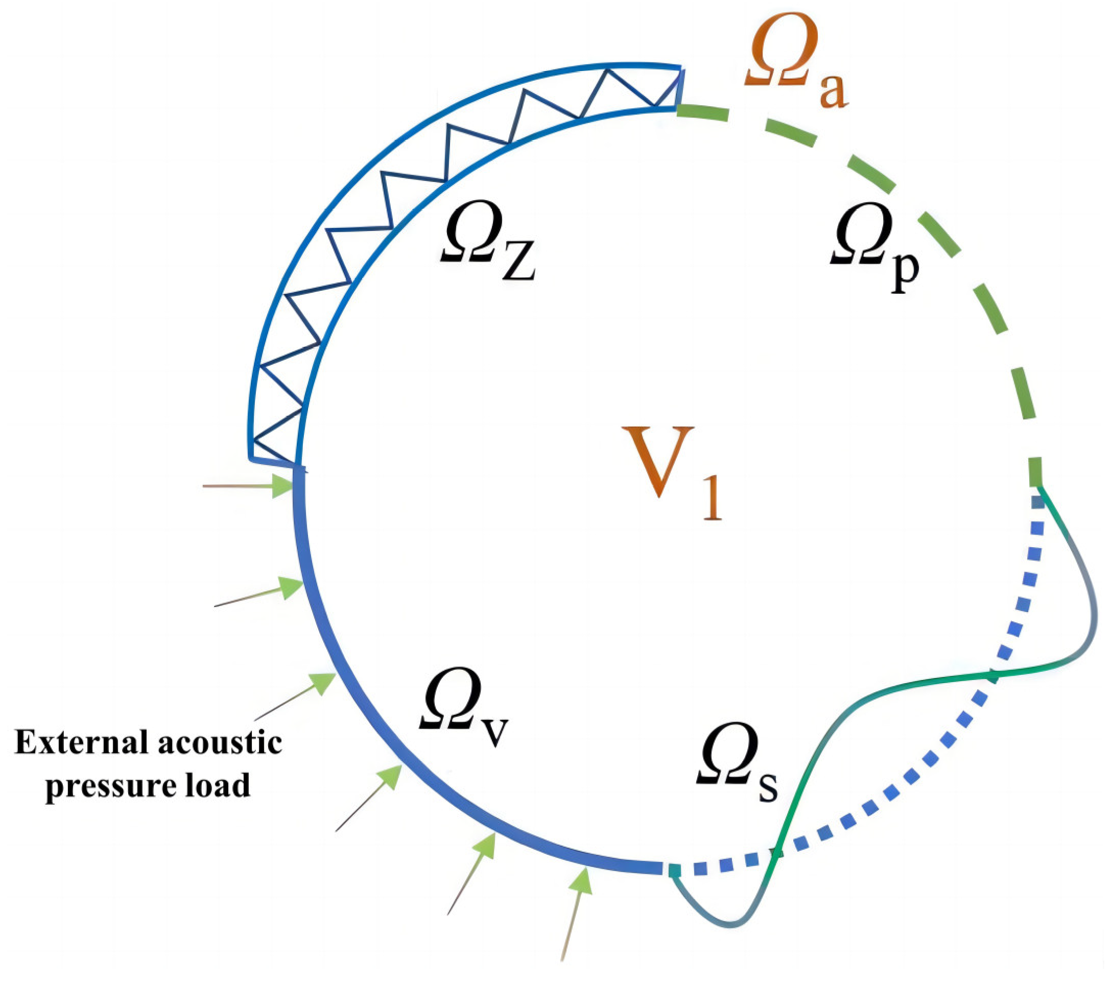
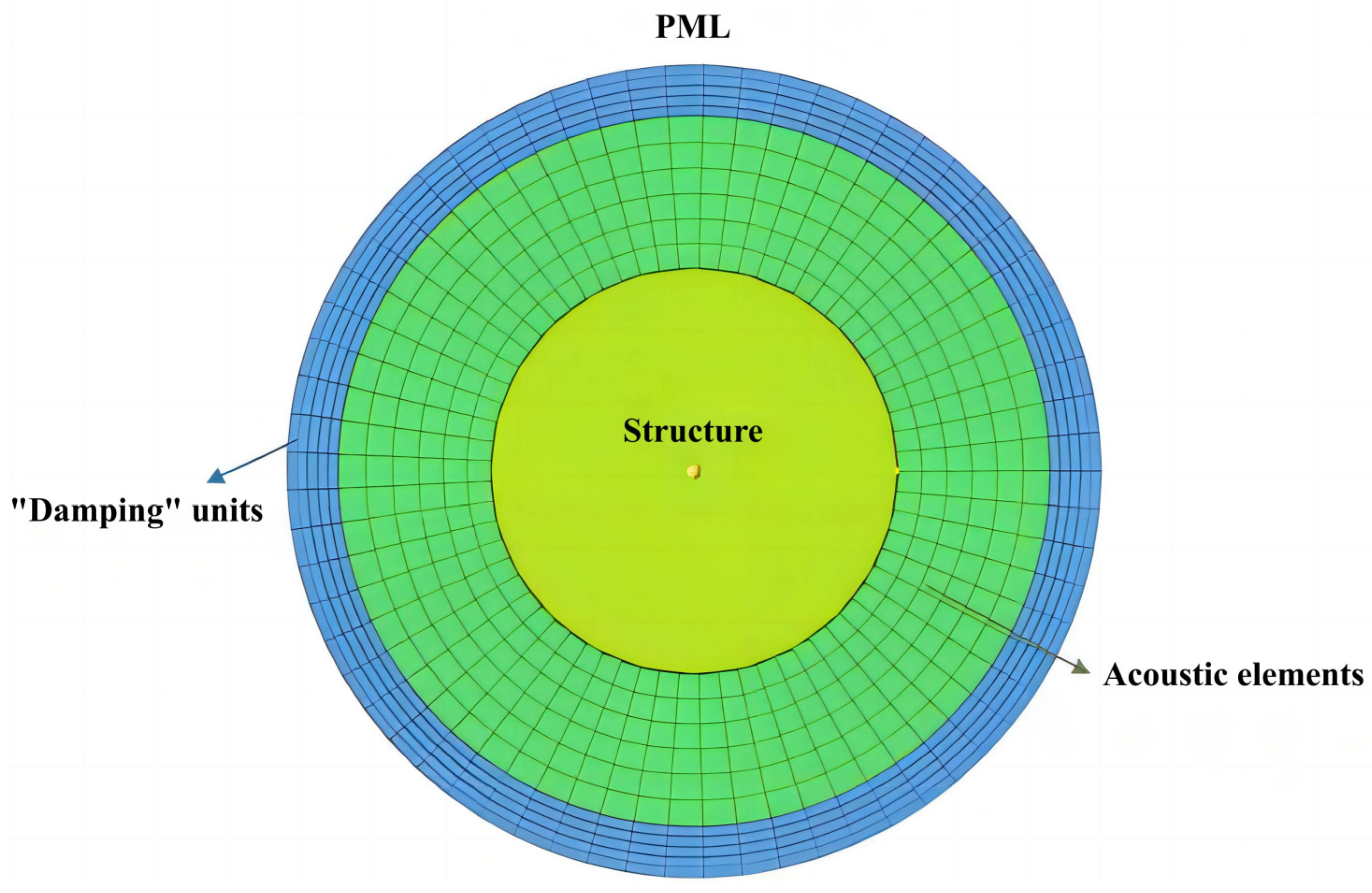
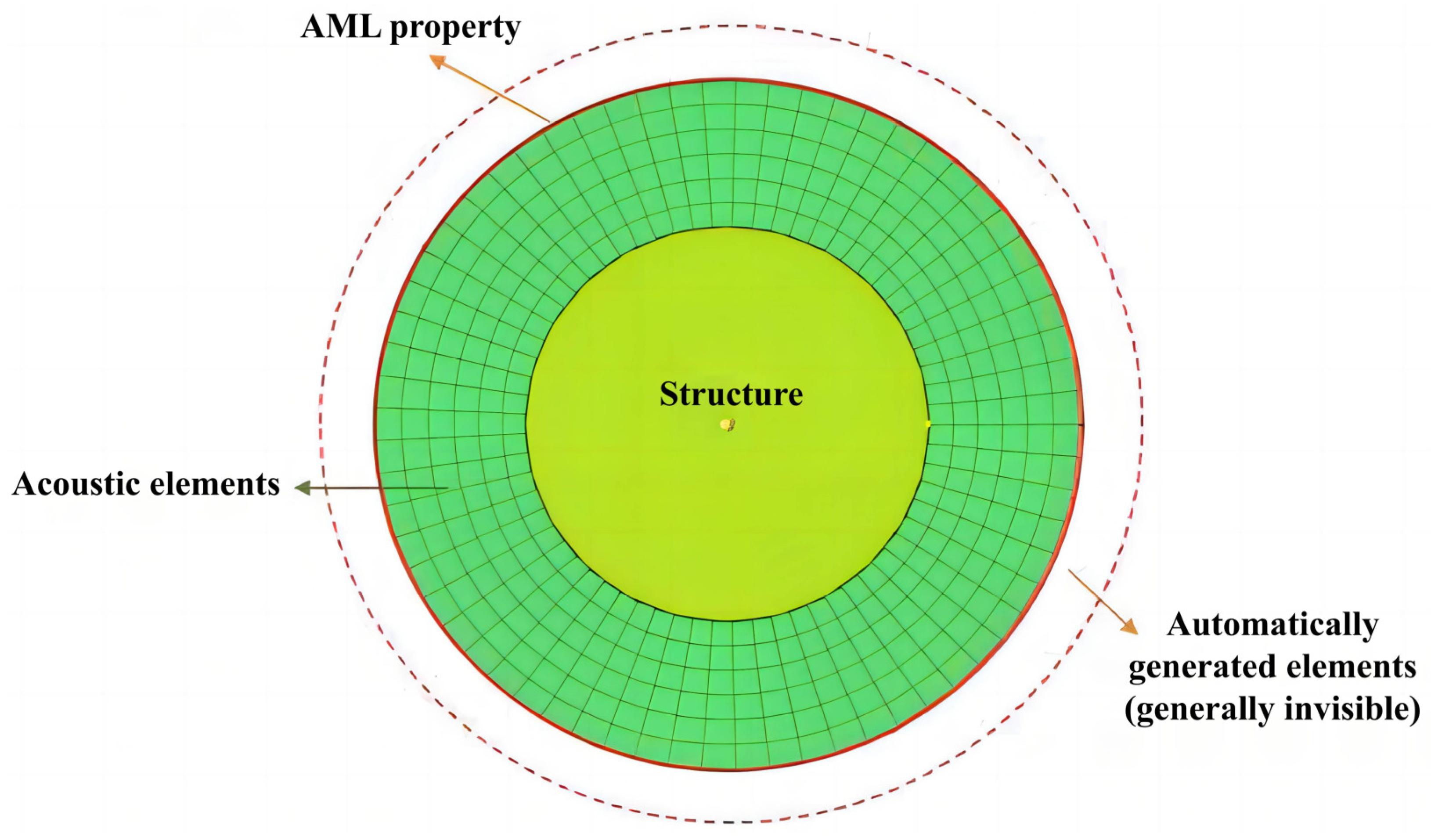
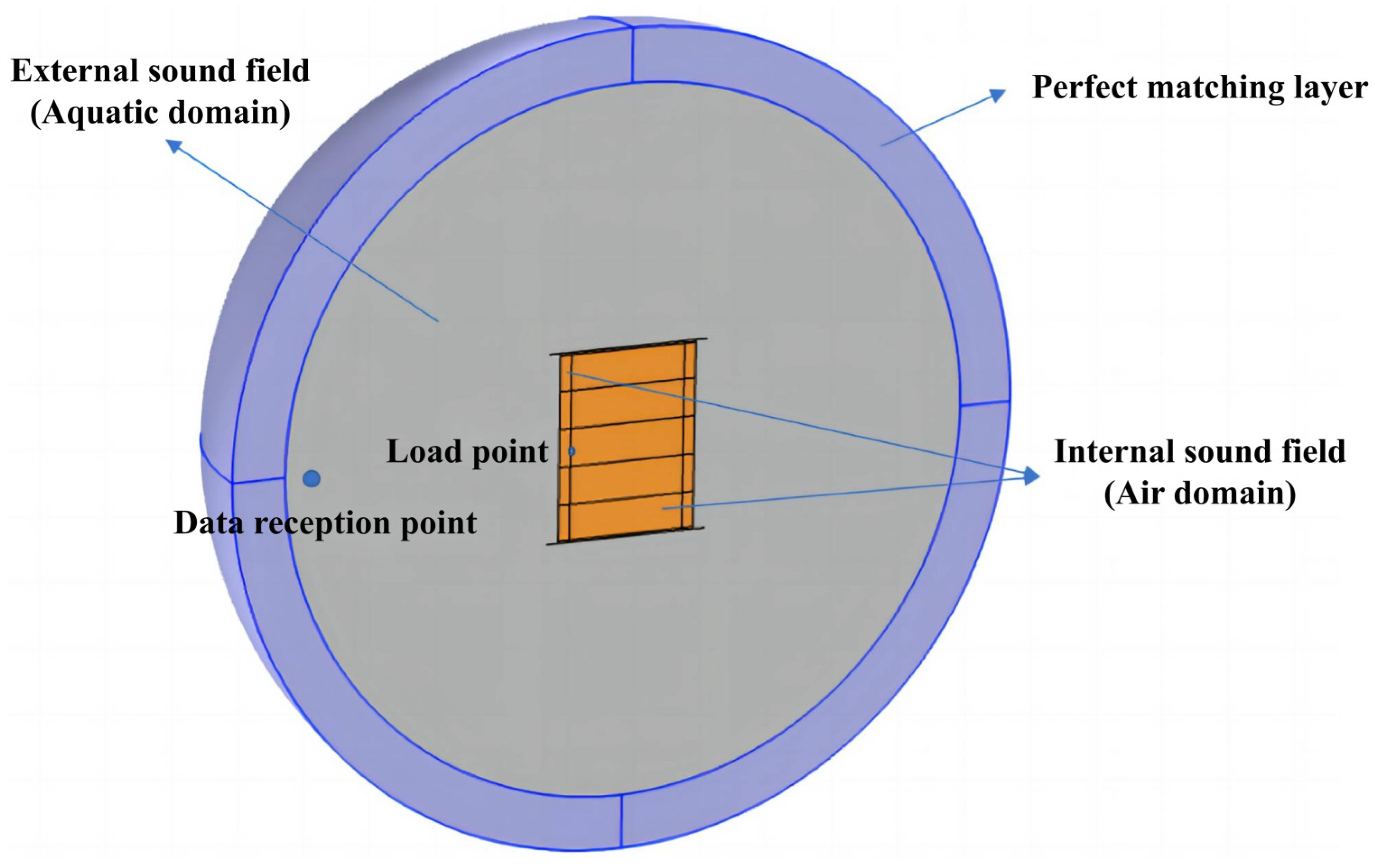
2.2. Outer Acoustic Field

To address such problems involving unbounded spatial domains in finite element analysis, an artificial absorbing boundary surface is introduced at a certain distance from the outer surface Ω s of the structure. This allows for the computation of the bounded acoustic domain V1 formed by the structure’s outer surface Ω s and the artificial absorbing boundary surface Ω e , as shown in Figure 2.
A common type of absorbing boundary interface is the perfect match layer (PML), which is a virtual layer typically located at the edge of the simulation domain. It is implemented by introducing complex mathematical equations and difference equations [22]. At the artificial absorbing boundary interface Ω e within the bounded acoustic domain V1 in finite element discretization, “damping” elements are employed to approximately simulate the absorption of outgoing acoustic waves without consideration for their frequency and incident angle. The purpose is to absorb incoming waves without reflection, preventing waves from reflecting back from the boundary of the simulation region, as shown in Figure 3.
Following the same theory, the LMS SYSNOISE company has introduced the automatic match layer (AML) method. This method is similar to PML, as it is a virtual layer placed at the simulation domain’s edge. Its purpose is to absorb waves and reduce reflections [23]. Different approaches are typically used, such as introducing absorption coefficients or adjusting model parameters. As shown in Figure 4, the absorbing layer and absorption coefficients in AML are automatically defined by physical models and calculated frequencies. Consequently, compared to the PML method, the AML method reduces computational workload. Thus, with the decrease in computational workload, the predictive accuracy relying on absorbing elements has been enhanced. SYSNOISE is combined with the coupled finite element method to establish a finite element model for the considered structure. In a similar manner, the cylindrical shell and annular plate are set as the structural mesh components, described using shell elements. The air field, both internal and external acoustic fields represented by solid elements, is taken as the acoustic mesh components. Additionally, a porous core with absorbing fluid properties is included as part of the acoustic mesh. Coupling surfaces at the interaction boundaries between structural and acoustic components are used for calculating the vibration–acoustic coupling.

3. Numerical Simulation Analysis

The complexity of the vibration and acoustic radiation issue in micro-perforated laminated cylindrical shells surpasses that of the conventional double-shell concern. It requires the consideration of the coupling of acoustic cavities that the micro-perforations create. Additionally, the inclusion of other acoustic materials within the shell further complicates the utilization of theoretical analytical solutions to describe the situation. Therefore, it is necessary to use COMSOL 6.0 to investigate their vibrational and acoustic radiation performance and study comprehensive optimization problems with more variables and constraints.

3.1. Establishment and Verification of a Finite Element Model for Cylindrical Shells

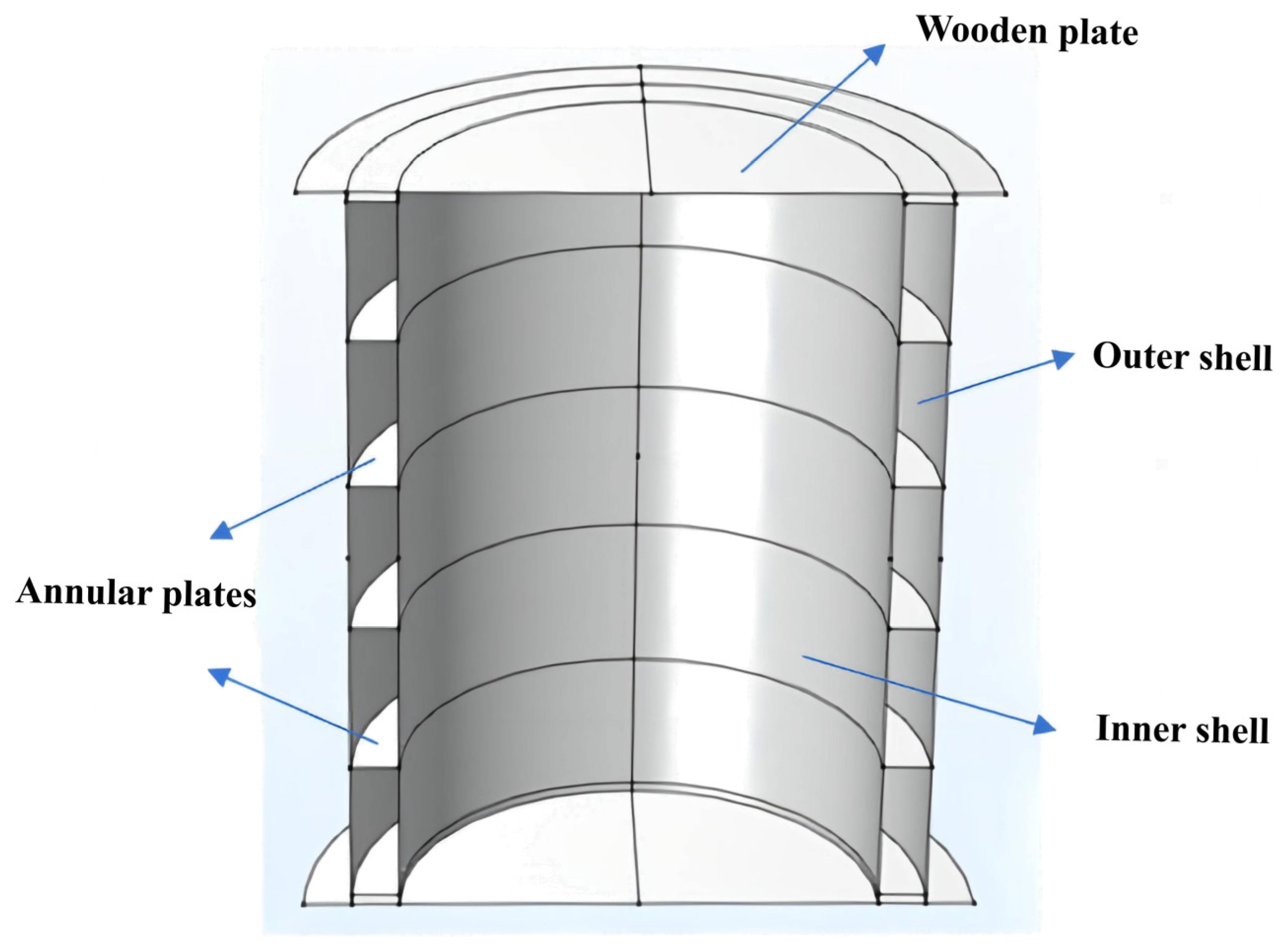
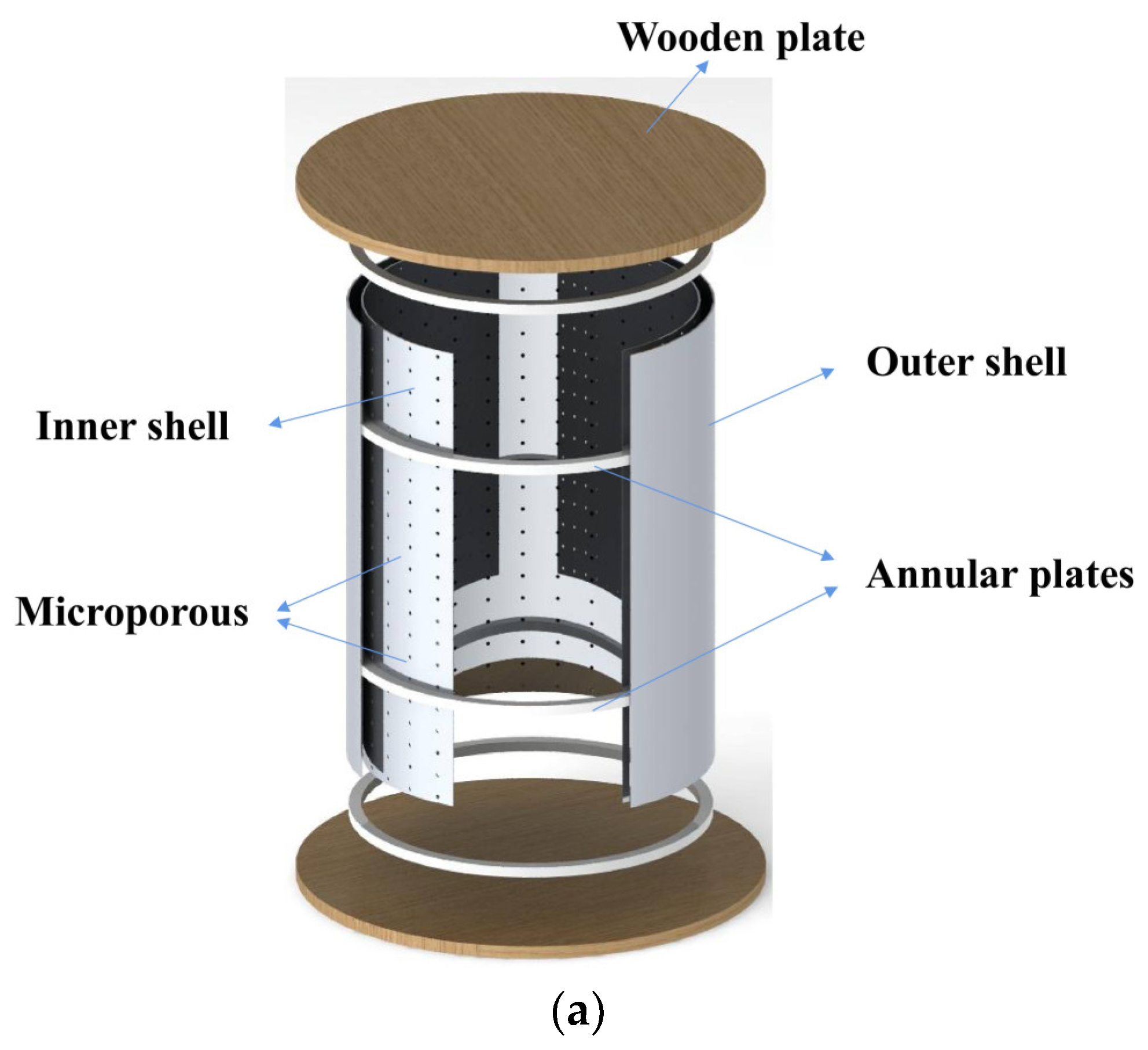
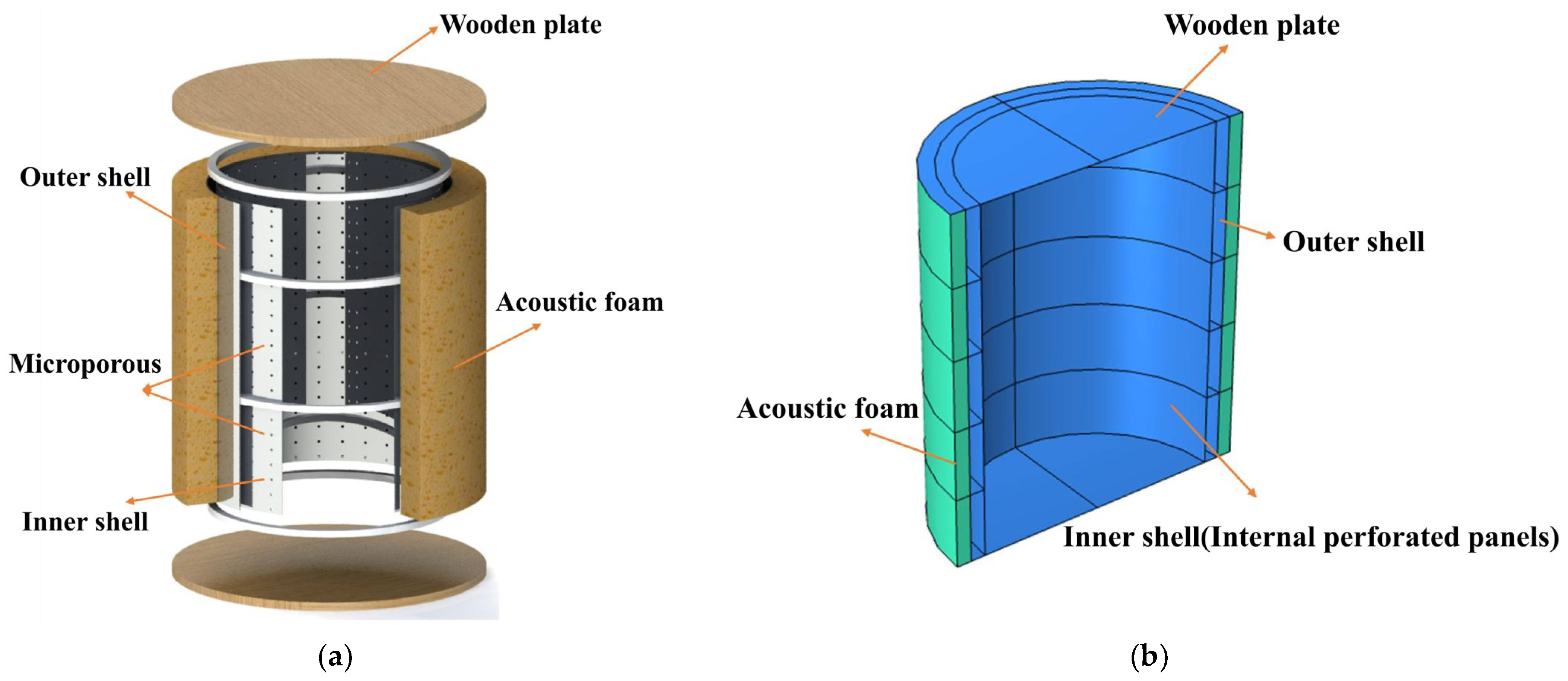
3.1.1. Model Establishment

Following an underwater experimental study on the vibration and acoustic radiation of double-layer shells by Jiang [24], a corresponding finite element simulation model is established. The initial pre-processing, as shown in Figure 5, involves the construction of a geometric model based on the dimensions of the experimental components reported in the literature. The geometric parameters of the two-layer cylindrical shell are as follows: the length of the cylindrical shell is l = 0.8 m, the radius of the inner shell is R1 = 0.25 m, the radius of the outer shell is R2 = 0.3 m, and the thickness of both the inner and outer shells is h = 2 mm; the thickness of the rib plate is hr = 10 mm and the spacing is hdis = 160 mm. Both ends of the cylindrical shell are sealed with steel plates. Upper and lower cover plates are constructed in the finite element model to match the experimental components. The cover plates have a radius of Ra = 0.35 m and a thickness of ha = 10 mm. Simultaneously, based on the experimental content, the hydrophone is located at a radial distance of 1.25 m from the exciter, and, using this information, we construct the inner and outer acoustic field, as shown in Figure 6.
Regarding the material properties, the inner and outer shells of the double-layer cylindrical shell, the annular ribs, and the upper and lower cover plates are all made of steel. The medium between the shells and inside the shell is air, while the external medium is water. The specific simulation parameters are presented in Table 1.
In the literature, the authors applied a 20 N force using an exciter at the midpoint of the inner shell of the model. Simultaneously, they adjusted gravity with weights to immerse the double-layer cylindrical shell in water, without any additional constraints. Therefore, during finite element simulations, an external load was set as a point excitation applied to the middle position of the inner shell, with a force magnitude of 10 N, considering the symmetry of the model. Furthermore, no additional constraint conditions were imposed on the model, meaning the double-layer cylindrical shell was in a free state.
Subsequently, mesh partitioning is carried out. The finite element software includes an internal “Mesh” module for fast and convenient mesh partitioning. This module allows the acoustic mesh sizes to be automatically adjusted during the calculation process according to the corresponding calculation frequencies, significantly reducing the calculation time while maintaining accuracy requirements. In this module, the maximum frequency is set to 1500 Hz and the number of mesh elements per wavelength is set to five to meet the accuracy requirements of the simulation.
Calculations are performed within the frequency range of 250–1500 Hz, as indicated in the literature. The analysis of the vibration and acoustic radiation performance of the double-layer cylindrical shell is completed with the default solver. Subsequently, sound pressure levels are obtained for the purpose of data comparison.

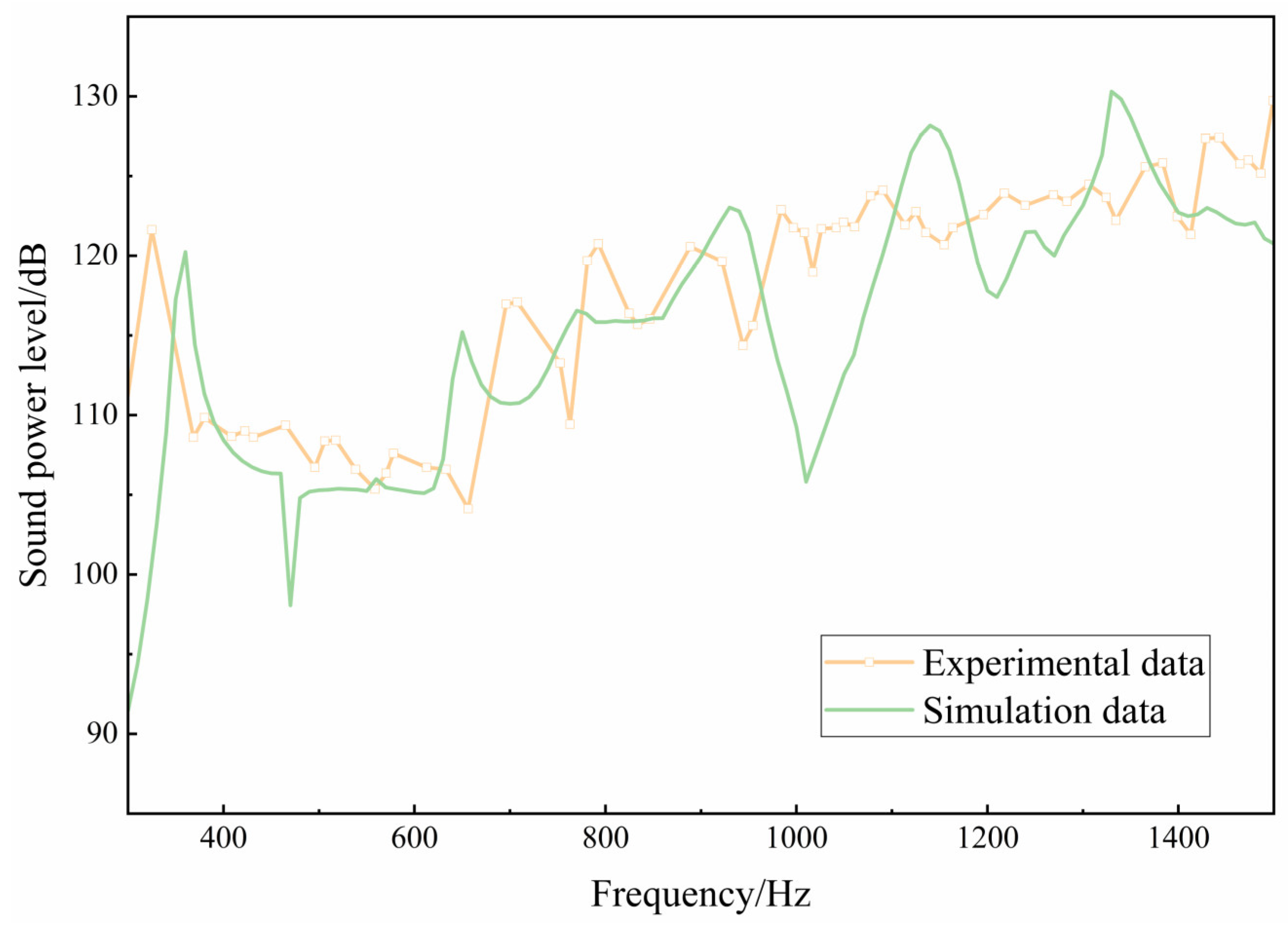
3.1.2. Validation of Finite Element Calculations

The comparison between the sound pressure levels inside the shell obtained through finite element simulation and the experimental results from the literature is shown in Figure 7. The experimental and simulated results are highly consistent for frequencies below 1000 Hz. However, when the solving frequency exceeds 1000 Hz, discrepancies between the simulation and experimental data emerge. This is primarily attributed to the higher modal density of the structure in the high-frequency range, leading to reduced accuracy in finite element simulations. As a result, the high-frequency results exhibit significant fluctuations, resulting in mismatches between the simulation and experimental data. Moreover, frequencies beyond this range are outside the scope of the study. However, upon comprehensive analysis, the finite element simulation outcomes for frequencies under 1000 Hz demonstrate a considerable level of consistency with experimental data obtained from the literature. The sound pressure level curves almost coincide, indicating the reliability of the approach used in the investigation.

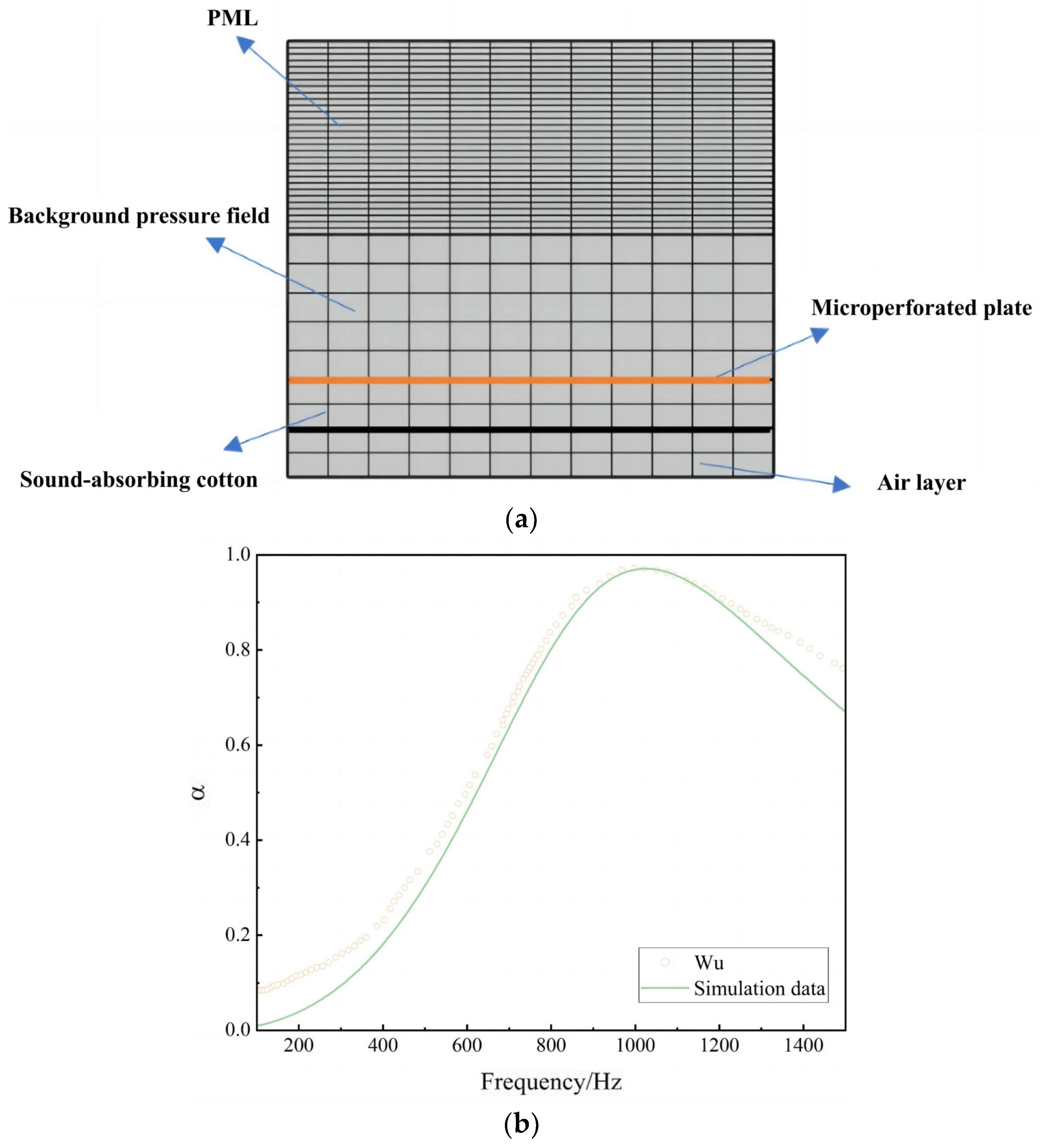
3.2. Establishment and Validation of a Micro-Perforated Finite Element Model

Directly simulating micro-perforations would drastically increase simulation time and computer memory requirements due to their small size. Therefore, an alternative approach is used to integrate the sound absorption properties of micro-perforations into the structure. This alternative approach uses the “Internal Perforated Plate” module in COMSOL to characterize the acoustic performance of a micro-perforated plate.
The experimental parameters for the acoustic impedance of the composite micro-perforated plate are taken from the literature [25]. The following parameters are employed: the circular micro-perforated plate has a diameter of 100 mm, a thickness of 1 mm, a micro-perforation hole diameter of 0.8 mm, and a perforation ratio of 1.67%. Moreover, the Johnson–Champoux–Allard (JCA) model is utilized to characterize the acoustic properties of the porous material. The fibrous acoustic foam used as a porous material exhibits a porosity of 0.97, an air flow resistivity of 73,145.7 Pa·s/m2, and thermal and viscous characteristic lengths of 0.594 mm. Additionally, it has a tortuosity factor of 1.67. A micro-perforated plate is closely incorporated into the acoustic foam to create a composite structure, with a 10 mm air gap positioned behind it. Figure 8a displays the finite element computational model formulated using these parameters.
From Figure 8b, it can be observed that when the solving frequency exceeds 1000 Hz, the accuracy of the finite element simulation method decreases due to the higher modal density of the composite structure in the high-frequency range. This leads to deviations between the simulation results and experimental data, which are also outside the research frequency range. However, overall, the simulation results are in good agreement with the experimental data. Therefore, the finite element method demonstrates the capability to accurately predict the acoustic performance of micro-perforated composite structures.

4. The Influence of Micro-Perforated Shells on the Vibration and Acoustic Radiation of Micro-Perforated Sandwich Cylindrical Shells

4.1. The Influence of a Sandwich Structure on the Vibration and Acoustic Radiation Performance of Cylindrical Shells

A preliminary design for the micro-perforated ring-stiffened sandwich cylindrical shell, as shown in Figure 9a, has been proposed. Additionally, three comparative models have been designed to investigate the vibration and acoustic radiation performance of different sandwich structures in the free air field within the medium-to-low-frequency range (1–1000 Hz).
As shown in Figure 9a, the micro-perforated ring-stiffened sandwich cylindrical shell consists of upper and lower aluminum thin cover plates, a micro-perforated inner shell, an outer shell, and four ring stiffeners. The geometric parameters of the structure are as follows: the length of the cylindrical shell is l = 720 mm, the inner shell radius is R1 = 250 mm, the outer shell radius is R2 = 274.7 mm, and the thickness of both the inner and outer shells is h1 = 2.7 mm; the intermediate ring stiffener has a thickness of hr = 1.6 mm and the spacing is hdis = 144 mm; the micro-perforation hole diameter is 0.1 mm and the perforation ratio is 0.1%. Additionally, both ends of the sandwich cylindrical shell are sealed with cover plates, where the cover plate radius is Ra = 350 mm and the thickness is hp = 2 mm. The structural material parameters are as follows: the inner and outer shells, upper and lower cover plates, as well as the annular ribs are all made of aluminum. Simultaneously, the material for the inner and outer acoustic fields is air. The material parameters for aluminum are listed in Table 2, while the material parameters for air are found in Table 1.
As shown in Figure 9b, the ring-stiffened sandwich cylindrical shell includes upper and lower aluminum thin cover plates, an inner shell, an outer shell, and four ring stiffeners. The inner shell of this structure does not contain micro-perforations, while the remaining geometric parameters and material parameters remain consistent with the micro-perforated ring-stiffened sandwich cylindrical shell. As shown in Figure 9c, the ribless sandwich cylindrical shell includes only upper and lower aluminum thin cover plates, an inner shell, and an outer shell. In Figure 9d, on the basis of the ribless sandwich structure, micro-perforations are introduced into the inner shell of the ribless structure, with a micro-perforation hole diameter of 0.1 mm and a perforation ratio of 0.1%.
The simulation load comprises a point force excitation with a 10 N magnitude, applied at the inner shell center, radially outwards. Additionally, a sound point source, located at the center of the inner cavity and with a radiated power of 1 W, is included. The boundary conditions entail free ends on both sides of the shell. The simulation considers a frequency range of 1–1000 Hz.
Figure 10 illustrates a contrast of the radiated sound power level with and without micro-perforated structures. In the presence of the rib (Figure 10a), micro-perforations have an effect solely on the peak of the structural radiated sound power level within the frequency range of 1–500 Hz, with negligible impact on other frequencies. Within this frequency range, the structure’s resonance is primarily caused by the upper and lower thin cover plates. As demonstrated in Figure 11a, the shell vibration’s lowest natural frequency is 554.44 Hz. Since the cover plates lack micro-perforated structures, the effect of the micro-perforations is weaker. Within the range of 500–1000 Hz, the micro-perforated structure can effectively reduce the radiated sound power level at the characteristic frequency of the shell while reducing the acoustic field-structure resonance peaks (e.g., 600–700 Hz), thereby lowering the structural radiated sound power level. Similarly, for the case without ribs (Figure 10b), within the frequency range of 1–300 Hz, the structure with micro-perforations has an impact only at the peak of the structural radiated sound power level, with minimal influence at other frequencies. Within the 300–1000 Hz frequency range, the micro-perforated structure can effectively reduce the radiated sound power level at the characteristic frequency of the shell while reducing the acoustic field-structure resonance peaks (e.g., 600–800 Hz), thus lowering the structural radiated sound power level. From the perspective of overall radiated sound power level, within the 1–1000 Hz frequency range, the overall radiated sound power levels of the micro-perforated ring-stiffened sandwich shell and the ring-stiffened sandwich shell are 135.59 dB and 135.77 dB, respectively. For the ribless sandwich shell and the ribless micro-perforated sandwich shell, the overall radiated sound power levels are 135.67 dB and 135.45 dB, respectively. Therefore, micro-perforations can reduce the overall radiated sound power level of the structure to some extent.
Figure 12 shows a comparison of the radiated sound power levels with and without ribs in the structure. It can be seen that the structure with ribs has fewer structural resonance peaks. This is because the ribs enhance the stiffness of the structure, reducing structural vibrations. From the perspective of overall radiated sound power level, within the 1–1000 Hz frequency range, the overall radiated sound power levels of the micro-perforated rib-stiffened shell and the ribless perforated shell are 135.59 dB and 135.45 dB, respectively. The overall radiated sound power levels of the rib-stiffened shell and the ribless shell are 135.77 dB and 135.67 dB, respectively. The sound power radiated by the structure with ribs may be lower due to the fact that the energy is mainly transferred through the ribs, whereas without ribs, the medium between the shells becomes the primary path for radiated sound energy to pass through [26]. It is evident that making a rational design for ribs is essential in reducing the radiated sound energy of the shell when arranging ribs to enhance structural stiffness.
In conclusion, micro-perforations can decrease the radiated sound power level at structural natural frequencies, reduce the amount of peaks in the radiated sound power level curve of the shell, and, to a certain extent, diminish the overall radiated sound power level of the structure. In the meantime, ribbed structures enhance the shell’s stiffness, shifting the natural frequencies to higher frequencies, and decreasing the peak values in the radiated sound power level curve. Therefore, micro-perforated rib-stiffened cylindrical shells offer a distinct advantage in mitigating the radiation of vibrational sound from structural components.

4.2. The Influence of Micro-Perforation on the Vibration and Acoustic Radiation Performance of Cylindrical Shells

With a lower radiated sound power level than the non-micro-perforated rib-stiffened cylindrical shell in Section 4.1, the investigation in this section aims to unveil how micro-perforation parameters, such as perforation rate and micro-hole diameter, affect the vibration and sound radiation performance of the micro-perforated rib-stiffened structure. The basic geometric parameters and structural parameters maintain their consistency with the ones in Section 4.1.
To examine the impact of micro-hole perforation rate on the vibration and sound radiation properties of the micro-perforated rib-stiffened cylindrical shell structure, finite element simulation models were created. The models featured perforation rates of 0.05%, 0.01%, 0.15%, 0.2%, 1%, and 2%, while the other geometric and material parameters of the structure remained unaltered. The vibration and sound radiation characteristics of the micro-perforated laminated cylindrical shell were analyzed in an unconfined state across a frequency range of 1–1000 Hz. Evaluation of the resulting sound power level spectrum is presented in Figure 13. As shown in the figure, with a micro-hole diameter of 0.1 mm and other parameters unchanged, within the specified range of variation, as the perforation rate increases, the peak of the structure’s sound radiation power level curve significantly decreases. Additionally, the number of peaks in the 500–700 Hz range also decreases, corresponding to a reduction in the structural acoustic resonance peaks. From the perspective of the overall sound radiation power level, within the range of 1–1000 Hz, the structure’s overall sound radiation power levels for inner shell perforation rates of 0.05%, 0.01%, 0.15%, 0.2%, 1%, and 2% are 135.69 dB, 135.59 dB, 135.51 dB, 135.45 dB, 134.90 dB, and 134.62 dB, respectively, with the structure’s overall sound radiation power level decreasing as the perforation rate increases.
Following the design of the previous experiment, finite element simulation models with micro-hole diameters of 0.02 mm, 0.06 mm, 0.1 mm, 0.14 mm, and 0.5 mm were constructed to investigate the influence of micro-pore diameter on the structural vibration and acoustic radiation performance. The radiation acoustic power level frequency spectra within the 1–1000 Hz frequency range were computed, as shown in Figure 14. It can be seen from the figure that, with a perforation rate of 0.1% and other parameters held constant within the indicated range, as the micro-hole diameter increases continuously, the peak value of the structural radiation acoustic power level curve significantly decreases. Moreover, there is a noticeable reduction in the peaks around 400 Hz and in the range of 600–700 Hz. From an analysis of overall radiation acoustic power levels within the 1–1000 Hz frequency range, it was found that the structural acoustic power levels for inner shell micro-hole diameters are as follows: 135.82 dB, 135.72 dB, 135.59 dB, 135.48 dB, and 134.18 dB. The overall structural radiation acoustic power level follows a downward trend as micro-hole diameter increases.
Findings from the assessment of two variables imply that micro-perforated structures can effectively diminish structural radiated sound power levels at specific frequencies and, to a certain extent, decrease the overall radiated sound power levels from a structure. This is due to the fact that when sound waves pass through micro-perforated structures, a part of the sound energy is absorbed and transformed into heat instead of being reflected or transmitted, which consequently leads to a reduction in total sound power. However, the reduction in the overall radiated sound power level is not significantly notable due to the limited scope of its effect. Micro-perforated structures have inherent acoustic resonance frequencies, which are determined by the geometric dimensions of the small holes and material characteristics. When sound waves reach or match the inherent resonance frequencies, micro-perforated structures create a resonance effect. This phenomenon leads to a noteworthy sound absorption within the porous material, resulting in reduced radiation [27].

5. The Influence of Foam Laying on the Vibration and Acoustic Radiation Performance of Micro-Perforated Sandwich Cylindrical Shells

Section 4 explored how the shell structure and micro-perforation parameters affect the vibrational acoustic radiation performance of micro-perforated laminated cylindrical shells. The study found that micro-perforations can decrease sound power levels near the shell’s natural frequencies. However, it did not yield noteworthy outcomes in reducing overall structural acoustic radiation. In this chapter, the surface of the structural shell will be treated with sound-absorbing materials to decrease the outward radiation of acoustic energy. The study will explore how variables such as foam material type, thickness, and laying method affect the structure’s vibration and acoustic radiation performance.
This chapter examines a laminated shell structure with foam and micro-perforations, composed of upper and lower wooden cover plates, a micro-perforated inner shell, an outer shell, four ring ribs, and an outer shell surface sound-absorbing material layer, as illustrated in Figure 15a. Additionally, a corresponding finite element simulation model is established, as depicted in Figure 15b. The outer shell radius is R2 = 290 mm, while the diameter of the micro-holes measures 0.5 mm. Meanwhile, the laminated cylindrical shell is sealed at each end with wooden cover plates measuring hp = 20 mm in thickness. The radius measurement is equivalent to the sum of the outer shell thickness and the foam layer thickness, and all other geometric parameters correspond to those presented in Figure 9. The structural material parameters are as follows: the inner and outer shells, as well as the annular ribs, are all made of aluminum. The upper and lower cover plates are constructed from wood. Simultaneously, the material for the inner and outer acoustic fields is air. The material parameters for wood can be found in Table 3, while the material parameters for air and aluminum are listed in Table 1 and Table 2, respectively.

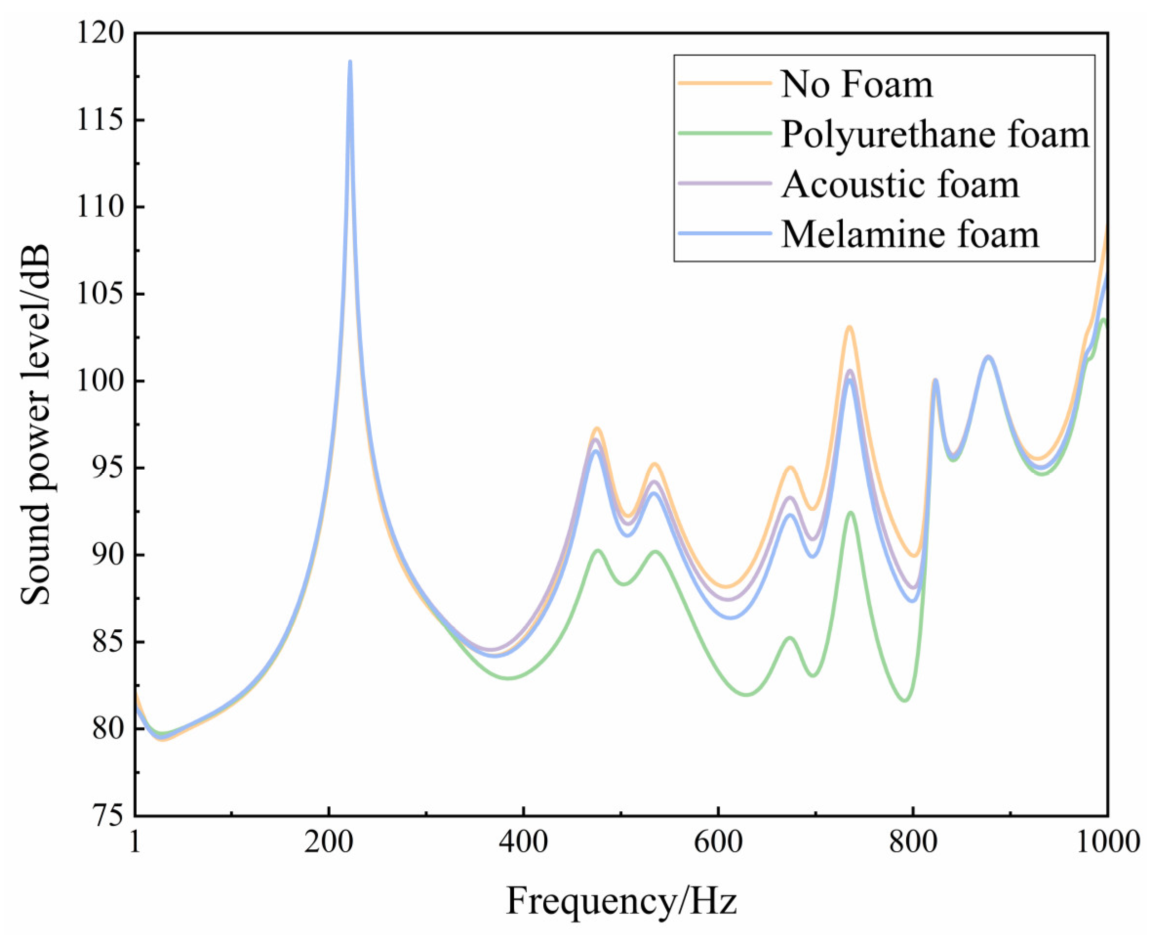
5.1. The Influence of Foam Type on the Vibration and Acoustic Radiation Performance of Cylindrical Shells

In this section, three types of porous sound-absorbing materials, namely polyurethane foam, acoustic foam, and melamine foam, will be selected to investigate the impact of different porous internal structures on the vibration and acoustic radiation performance of micro-perforated laminated shells.
Porous material structures consist mainly of a complex network of interlacing foam skeletons and internal pores that include closed, half-open, and open pores. Consequently, studying sound propagation within porous materials at a microscopic scale presents a challenge. The Johnson–Champoux–Allard (JCA) porous material model is an equivalent fluid model utilized for simulating the propagation of sound waves in porous materials. Five acoustic parameters, namely porosity, static flow resistivity, tortuosity factor, viscous characteristic length, and thermal characteristic length, are employed to comprehensively describe the internal sound field propagation in porous materials [28,29]. This enables a thorough characterization of the acoustic behavior of such materials. Based on this methodology, porous sound-absorbing materials are considered as a special fluid medium for simulation purposes. The acoustic parameters for the three types of porous material structures are presented in Table 4. Based on this, the vibration and acoustic radiation performance of the micro-perforated laminated shell when 40 mm of different types of foam is applied is calculated and solved in the frequency range, as shown in the radiation acoustic power level frequency spectra in Figure 16. From the figure, it can be observed that within the 300–810 Hz frequency range, the application of sound-absorbing foam effectively reduces the radiation acoustic power level, with polyurethane foam performing the best, followed by melamine foam, and acoustic foam showing the poorest performance. Within this frequency range, the overall trend of the structural radiation acoustic power level curve is reduced with the application of foam. Specifically, the application of polyurethane foam, acoustic foam, and melamine foam can reduce the structural radiation acoustic power level by up to 11.14 dB, 2.52 dB, and 3.17 dB, respectively. In the 900–1000 Hz frequency range, sound-absorbing foam once again demonstrates its effectiveness in reducing the structural radiation acoustic power level, with polyurethane foam showing the most remarkable performance.

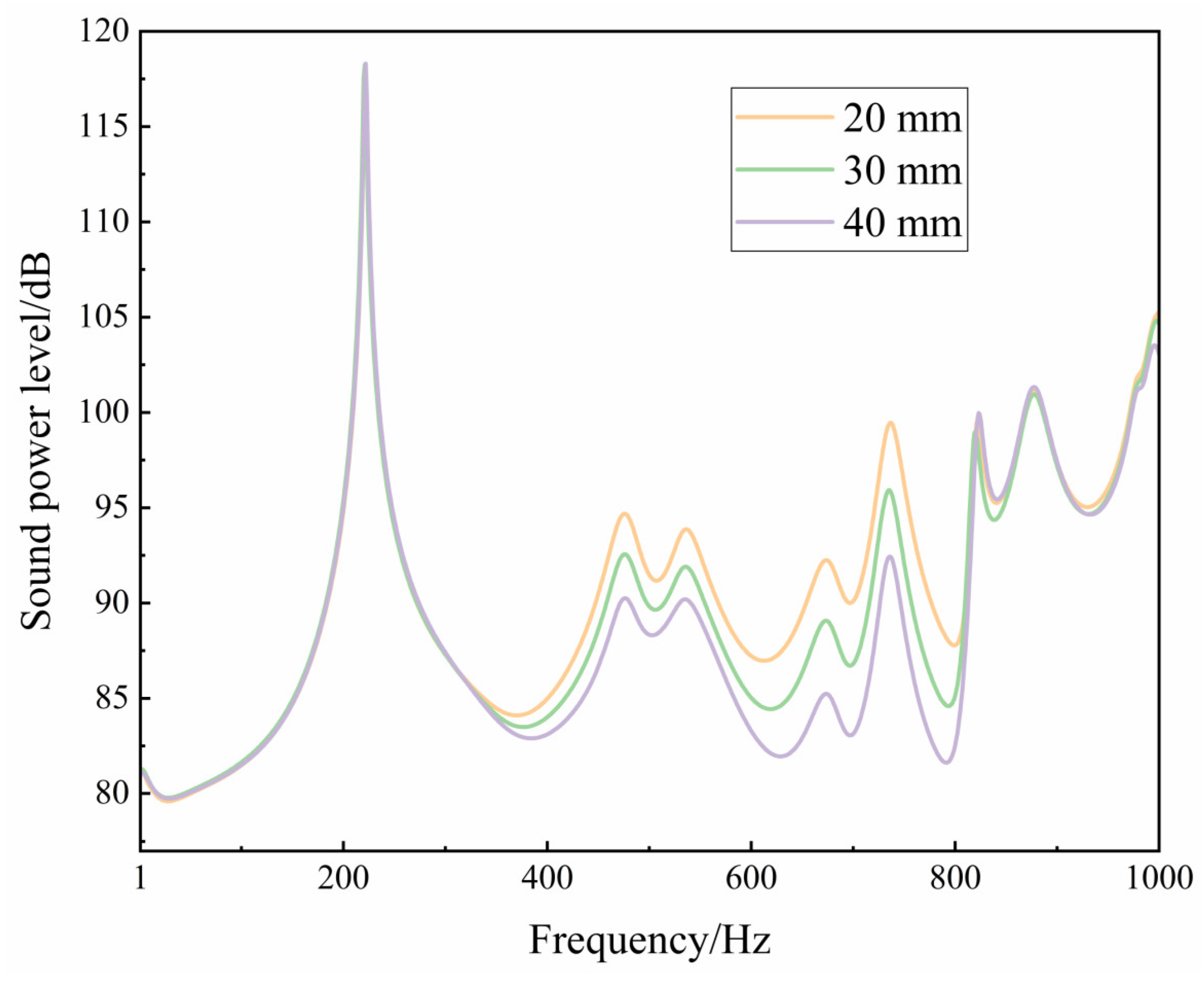
5.2. The Influence of Sound-Absorbing Foam Thickness on the Vibration and Acoustic Radiation Performance of Cylindrical Shells

To investigate the effect of sound-absorbing foam thickness on the vibration and acoustic radiation performance of micro-perforated laminated cylindrical shell structures, while keeping the structural geometry parameters and material parameters unchanged, finite element simulation models were established by varying only the thickness of the sound-absorbing foam to 20 mm, 30 mm, and 40 mm, respectively. The vibration and acoustic radiation performance of the micro-perforated laminated cylindrical shell at different foam thicknesses in the 1–1000 Hz range was explored, and the calculated radiation acoustic power level frequency spectra are shown in Figure 17.
According to the graph, an increase in polyurethane foam thickness leads to a significant reduction in the structural radiation acoustic power level curve in the 380–810 Hz frequency range. Structures with 20 mm, 30 mm, and 40 mm foam can reduce the level of radiation acoustic power up to 3.66 dB, 7.3 dB, and 11.14 dB, respectively, when compared to the scenario without foam. Considering the overall radiation acoustic power level, in the frequency range of 1–1000 Hz, structures with 20 mm, 30 mm, and 40 mm polyurethane foam have radiation acoustic power levels of 126.76 dB, 126.33 dB, and 126.01 dB, correspondingly. This implies that as the foam thickness increases, the overall radiation acoustic power level decreases.

5.3. The Influence of Sound-Absorbing Foam Coverage Rate on the Vibration and Acoustic Radiation Performance of Cylindrical Shells

To investigate the impact of sound-absorbing foam coverage rate on the vibration and acoustic radiation performance of micro-perforated laminated cylindrical shell structures, while keeping the other geometric parameters and material parameters constant, finite element simulation models were established for the influence of 40 mm polyurethane foam within the frequency range. Models with foam coverage rates of 0%, 20%, 60%, and 100% were sequentially created, and the simulated structural radiation acoustic power level frequency spectra are shown in Figure 18.
As observed from the graph, in the 1–300 Hz and 810–900 Hz frequency ranges, the structural radiation acoustic power level curves for different foam coverage rates are essentially consistent, indicating that sound-absorbing foam has a lower effect in the low-frequency range and does not significantly affect the structural outward radiation acoustic power. In the 300–810 Hz and 900–1000 Hz frequency ranges, as the foam coverage rate increases, the structural radiation acoustic power level curves noticeably decrease. This is due to the increase in the structure’s internal sound energy absorption associated with the increase in polyurethane foam coverage rate, thereby reducing the structural radiation acoustic power level. From an objective standpoint, the structures with 0%, 20%, 40%, 60%, 80%, and 100% coverage of polyurethane foam were tested for overall radiation acoustic power levels within the 1–1000 Hz frequency range. Results showed respective dB levels of 127.2, 126.80, 126.43, 126.26, 126.04, and 126.01. These findings suggest that the micro-perforated laminated cylindrical shell exhibits optimal acoustic performance with full foam coverage. Compared to the scenario without foam, the structures’ overall radiation acoustic power levels decrease by 0.4 dB, 0.77 dB, 0.94 dB, 1.16 dB, and 1.19 dB. The reduction magnitude diminishes as the coverage rate increases.

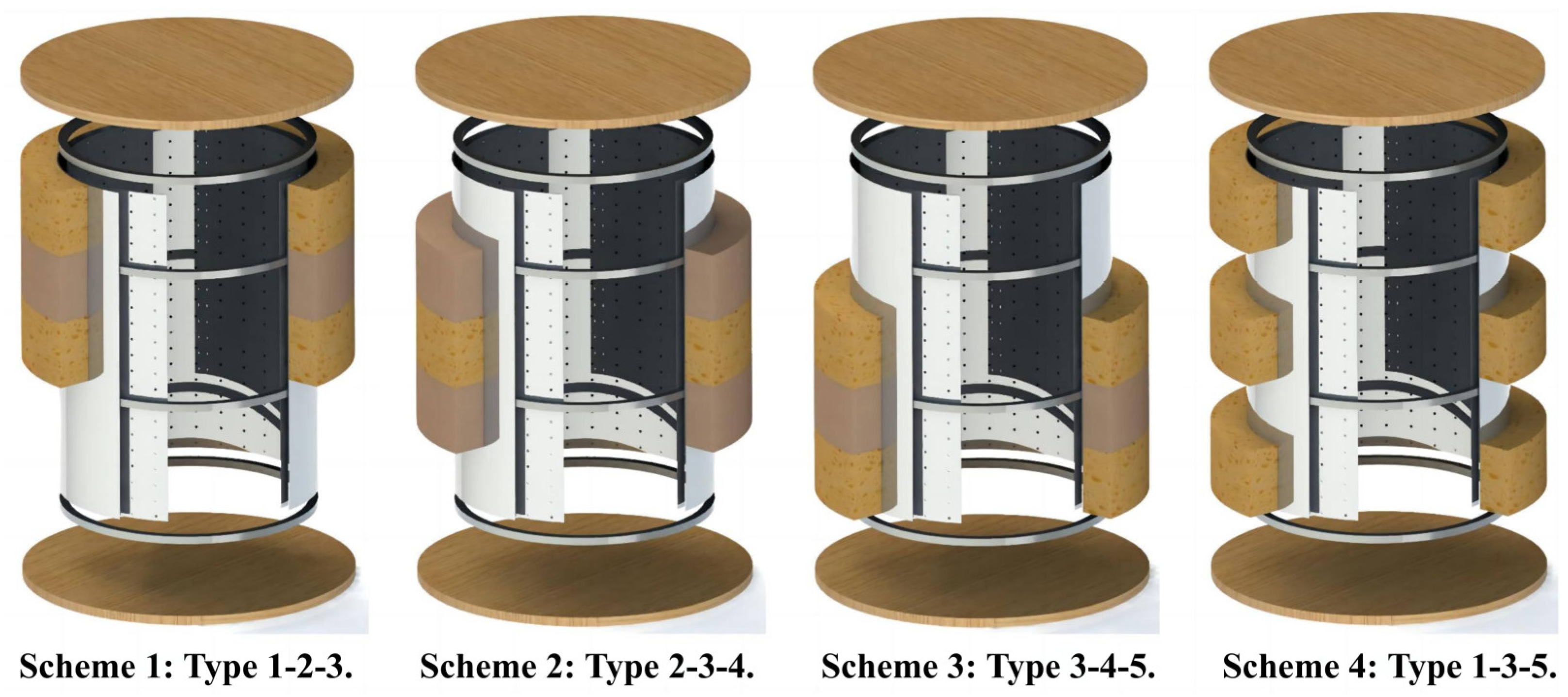
5.4. The Influence of Sound-Absorbing Foam Placement on the Vibration and Acoustic Radiation Performance of Cylindrical Shells

The results from Section 5.3 and Section 5.4 demonstrate the enhanced vibration and acoustic radiation performance of the structure with varying degrees of thickness and coverage rate of polyurethane foam. Nevertheless, the magnitude of improvement in the structural radiation acoustic power level decreases with an increase in foam coverage rate. To further investigate the impact of foam placement on the vibration and acoustic radiation performance of the structure, this section will examine the effect of the location of the foam placement.
To examine the effect of sound-absorbing foam positioning on the vibrational and acoustic radiation performance of micro-perforated laminated cylindrical shell structures, while maintaining constant geometric and material parameters, the foam is divided into five layers based on rib arrangements and numbered from top to bottom as 1–5. Four foam placement methods have been chosen, as demonstrated in Figure 19. All foam placements are polyurethane, and the disparities in the figure are for elucidating the placement methods. Assuming a foam thickness of 20 mm and a coverage rate of 60% inside the cylindrical shell cavity, this section examines the vibration and acoustic radiation performance of the micro-perforated laminated cylindrical shell subjected to different foam placement methods.
We created finite element simulation models for four foam placement schemes with a thickness of 20 mm, solving the vibration and acoustic radiation performance of the micro-perforated laminated cylindrical shell in the frequency range of 1–1000 Hz under free conditions. The computed results are displayed in Figure 20.
From the graph, it can be observed that the trends in structural radiation acoustic power levels for the four placement schemes are essentially the same. Moreover, in the 400–800 Hz frequency range, the curve for Scheme 2 is the lowest, the curves for Scheme 1 and Scheme 3 coincide, while the curve for Scheme 4 is the highest. This is attributed to the fact that the internal point force is located at the center of the inner shell, and the point source is positioned at the center of the inner acoustic field. Therefore, centrally and concentratedly distributed schemes are more effective in attenuating sound waves. Scheme 1 and Scheme 3 are symmetrically placed, and they have the same effect for symmetric external loads. Scheme 4 is symmetrically dispersed, and in this scheme, some foam has no effect on the middle region of sound waves, resulting in a higher structural radiation acoustic power level. From the perspective of overall radiation acoustic power level, in the 1–1000 Hz frequency range, the overall structural radiation acoustic power levels for Schemes 1–4 are 126.9 dB, 126.81 dB, 126.9 dB, and 126.91 dB, respectively. The maximum difference in overall radiation acoustic power level among the four schemes is only 0.1 dB. Therefore, changing the placement location has a relatively small impact on the structural radiation acoustic power level.

6. Conclusions

This study employs a finite element simulation analysis method and introduces micro-perforation acoustic parameters into the acoustic–vibration coupling model of laminated cylindrical shells. The accuracy of the finite element modeling method is verified through comparisons with experimental results from the literature. Based on this, the study investigates the influence of structural parameters, micro-perforation characteristics, foam materials, and foam installation methods on the vibration and acoustic radiation performance of laminated cylindrical shell structures within the 1–1000 Hz frequency range. The primary research work and findings of this paper are as follows:
  • Under the simultaneous excitation of point force and point source, perforations in the inner shell effectively reduce the radiation acoustic power level at the characteristic frequency of the shell and reduce the number of acoustic structural resonance peaks, thereby lowering the structural radiation acoustic power level. Within the selected parameter range, as the micro-perforation rate and perforation diameter increase, the overall structural radiation acoustic power level decreases significantly, and the corresponding peaks decrease. However, due to its narrow operating range, the reduction in the overall structural radiation acoustic power level is not significant;
  • In the frequency range of 1–1000 Hz, the position of sound-absorbing foam has the most significant impact on the vibration and acoustic radiation performance of the structure within the 300–810 Hz frequency range. Various types of foam can lessen the acoustic power level caused by structural radiation, with polyurethane being the optimal choice for reducing it up to 11.14 dB. Nonetheless, the foam’s placement has no effect on the natural vibration frequencies of the structure. When the foam thickness varies within the 80–810 Hz frequency range, the overall level of acoustic power radiated by the structure declines as the foam thickness increases. The performance reaches its maximum at a thickness of 40 mm, resulting in a decrease of up to 11.14 dB;
  • In the 300–810 Hz and 900–1000 Hz frequency ranges, as the sound-absorbing foam placement rate increases, the structural radiation acoustic power level gradually decreases, and the reduction values gradually diminish. Compared to the situation without the placement of sound-absorbing foam, the overall structural radiation acoustic power level is reduced by 0.4 dB, 0.77 dB, 0.94 dB, 1.16 dB, and 1.19 dB when 20%, 40%, 60%, 80%, and 100% foam is placed, respectively, indicating that the acoustic performance of the micro-perforated laminated cylindrical shell is optimal when fully equipped with foam;
  • In the frequency range of 1–1000 Hz and with no change in foam thickness, a 60% placement rate has a minimal effect on the level of structural radiation acoustic power, as the foam thickness is less than 6% of the cavity radius and only the placement location was modified. This finding indicates that to achieve better noise reduction results in practical applications, the relationship between foam thickness and acoustic wavelength must be considered.

Author Contributions

Conceptualization, B.L.; methodology, Z.Z.; validation, Z.Z.; formal analysis, Z.Z. and N.W.; resources, B.L.; data curation, Z.Z. and N.W.; writing—original draft preparation, N.W., Z.Z., W.K., L.W., Y.C., J.H. and S.C.; writing—review and editing, N.W.; visualization, Z.Z.; supervision, B.L.; project administration, B.L.; funding acquisition, B.L. All authors have read and agreed to the published version of the manuscript.

Funding

The work is supported by the 2022 Knowledge Innovation Dawn Special Plan Project (2022010801020393), Research and Innovation Initiatives of WHPU (2022J04). This work was finished at Wuhan Polytechnic University, Wuhan, China.

Institutional Review Board Statement

Not applicable.

Informed Consent Statement

Not applicable.

Data Availability Statement

The data in this study are available in the article.

Conflicts of Interest

The authors declare no conflict of interest.

References

  1. Xin, F.X.; Lu, T.J.; Chen, C.Q. External Mean Flow Influence on Noise Transmission through Double-Leaf Aeroelastic Plates. AIAA J. 2009, 47, 1939–1951. [Google Scholar] [CrossRef]
  2. Fuchs, H.; Zha, X. Micro-Perforated Structures as Sound Absorbers—A Review and Outlook. Acta Acust. United Acust. 2006, 92, 139–146. [Google Scholar]
  3. Fuchs, H.; Zha, X. Acrylic-glass sound absorbers in the plenum of the deutscher bundestag. Appl. Acoust. 1997, 51, 211–217. [Google Scholar] [CrossRef]
  4. Hou, J.; Zhu, H.; Yuan, S.; Liao, J. Transmission loss of flexible micro-perforated muffler with flexible back cavity for water filled pipelines. Acta Acust. 2021, 46, 405–414. [Google Scholar]
  5. Tian, Y.; Chen, J.; Liu, Z.; Lu, W.; Chen, X.; Han, J. Application of Microporous Fiber Composite Acoustic Board in the Noise Control Engineering of Urban Substations. Smart Grid 2016, 4, 988–992. [Google Scholar]
  6. Hu, S.; Chen, S.; Wu, X.; Cai, J.; Li, T.; Peng, J. Study of Design and Performance of Composite Resonance Absorption Barrier. Ind. Saf. Environ. Prot. 2019, 45, 77–80,96. [Google Scholar]
  7. Yang, J.; Cai, J.; Shao, C. Sound Insulation Property of the Composite Structure with Micro-perforated Panels and Honeycomb Core. Noise Vib. Control 2013, 33, 122–125,176. [Google Scholar]
  8. Kang, J.; Brocklesby, M.W. Feasibility of applying micro-perforated absorbers in acoustic window systems. Appl. Acoust. 2005, 66, 669–689. [Google Scholar] [CrossRef]
  9. Zhang, Q.; Mao, Y.; Qi, D. Effect of perforation on the sound transmission through a double-walled cylindrical shell. J. Sound Vib. 2017, 410, 344–363. [Google Scholar] [CrossRef]
  10. Zhang, Q.; Mao, Y.; Qi, D. Analytical Modeling of the Vibro-Acoustic Response of a Double-Walled Cylindrical Shell with Microperforation Excited by Turbulent Boundary Layer Pressure Fluctuations. J. Vib. Acoust. 2017, 140, 021012. [Google Scholar] [CrossRef]
  11. Zhang, Q. Sound transmission through micro-perforated double-walled cylindrical shells lined with porous material. J. Sound Vib. 2020, 485, 115539. [Google Scholar] [CrossRef]
  12. Allard, J.F.; Atalla, N. Propagation of Sound in Porous Media: Modelling Sound Absorbing Materials, 2nd ed.; Wiley-Blackwell: Hoboken, NJ, USA, 2009; p. 358. [Google Scholar]
  13. Aditya, L.; Mahlia, T.M.I.; Rismanchi, B.; Ng, H.M.; Hasan, M.H.; Metselaar, H.S.C.; Muraza, O.; Aditiya, H.B. A review on insulation materials for energy conservation in buildings. Renew. Sustain. Energy Rev. 2017, 73, 1352–1365. [Google Scholar] [CrossRef]
  14. Zhou, J.; Bhaskar, A.; Zhang, X. Sound transmission through double cylindrical shells lined with porous material under turbulent boundary layer excitation. J. Sound Vib. 2015, 357, 253–268. [Google Scholar] [CrossRef]
  15. Oliazadeh, P.; Farshidianfar, A.; Crocker, M.J. Experimental and analytical investigation on sound transmission loss of cylindrical shells with absorbing material. J. Sound Vib. 2018, 434, 28–43. [Google Scholar] [CrossRef]
  16. Darvish Gohari, H.; Zarastvand, M.R.; Talebitooti, R. Acoustic performance prediction of a multilayered finite cylinder equipped with porous foam media. J. Vib. Control 2020, 26, 899–912. [Google Scholar] [CrossRef]
  17. Shahsavari, H.; Kornokar, M.; Talebitooti, R.; Daneshjou, K. The study of sound transmission through sandwich cylindrical shells with circumferentially corrugated cores filled with porous materials. Compos. Struct. 2022, 291, 291. [Google Scholar] [CrossRef]
  18. Yang, X.; Chen, M.; Zhao, Y.; Dong, W. Characteristics and calculation method of sound radiation of cylindrical shell with porous sound-absorbing material under acoustic excitation. Chin. J. Ship Res. 2023, 18, 97–106. [Google Scholar]
  19. Liu, Y.; Liu, J.; Pan, G.-X.; Guo, L.; Huang, Q. A Design Method for Vibration and Acoustic Reduction of the Power System in an Underwater Automobile Glider. Int. J. Acoust. Vib. 2022, 27, 233–244. [Google Scholar] [CrossRef]
  20. Gaul, L.; Wenzel, W. A coupled symmetric BE–FE method for acoustic fluid–structure interaction. Eng. Anal. Bound. Elem. 2002, 26, 629–636. [Google Scholar] [CrossRef]
  21. Zheng, Z.; Li, B.; Yan, S.; Qi, M.; Wang, N.; Kuang, W.; Wen, J.; Ma, Y. Acoustic radiation performance investigation of a double-walled cylindrical shell equipped with annular plates and porous foam media. J. Low Freq. Noise Vib. Act. Control 2022, 42, 851–865. [Google Scholar] [CrossRef]
  22. Berenger, J.P. A perfectly matched layer for the absorption of electromagnetic waves. J. Comput. Phys. 1994, 114, 185–200. [Google Scholar] [CrossRef]
  23. Zhan, F.; Xu, J. Virtual. Lab Acoustics Acoustic Simulation Calculations from Beginner to Proficient; Northwestern Polytechnical University Press Co., Ltd.: Xi’an, China, 2013. [Google Scholar]
  24. Jiang, C. Analysis of Vibro-Acoustic Characteristics of Double Cylindrical Shell Underwater Based on Precise Transfer Matrix Method. Master’s Thesis, Wuhan University of Technology, Wuhan, China, 2019. [Google Scholar]
  25. Wu, J.; Liu, Z.; Wang, Q. Prediction of Acoustic Properties of Sound-absorbing Structures with Composite Micro-perforated Panels. Noise Vib. Control 2022, 42, 203–208. [Google Scholar]
  26. Chen, M.; Luo, D.; Chen, X.; Shen, R. Analysis of sound radiation characteristics of complex double shells. Acta Acust. 2004, 29, 209–215. [Google Scholar]
  27. Floss, S.; Czwielong, F.; Becker, S.; Kaltenbacher, M. Micro-perforated panels for noise reduction. E I Elektrotech. Und Infstechnik. 2021, 138, 171–178. [Google Scholar] [CrossRef]
  28. Champoux, Y.; Allard, J.F. Dynamic tortuosity and bulk modulus in air-saturated porous media. J. Appl. Phys. 1991, 70, 1975–1979. [Google Scholar] [CrossRef]
  29. Johnson, D.L.; Koplik, J.; Dashen, R.F. Theory of dynamic permeability and tortuosity in fluid-saturated porous media. J. Fluid Mech. 1987, 176, 379–402. [Google Scholar] [CrossRef]
Figure 1. Interior acoustic–vibration coupling system.
Applsci 13 11939 g001
Figure 2. Exterior sound and vibration coupling system with artificial absorption boundary.
Applsci 13 11939 g002
Figure 3. Schematic of a perfect matching layer.
Applsci 13 11939 g003
Figure 4. Schematic of an automatic matching layer.
Applsci 13 11939 g004
Figure 5. Schematic diagram of a finite element model for a double-layer cylindrical shell structure.
Applsci 13 11939 g005
Figure 6. Acoustic finite element model.
Applsci 13 11939 g006
Figure 7. Comparison of sound pressure level calculation results.
Applsci 13 11939 g007
Figure 8. Verification graph of a micro-perforated finite element model. (a) Finite element model of a micro-perforated plate; (b) comparative graph of literature results and simulation results.
Applsci 13 11939 g008
Figure 9. Schematic diagrams of different sandwich structures. (a) Micro-perforated ribbed sandwich cylinder shell structure; (b) ribbed sandwich cylinder shell structure; (c) ribless sandwich cylinder shell structure; (d) ribless perforated sandwich cylinder shell structure.
Applsci 13 11939 g009aApplsci 13 11939 g009b
Figure 10. Influence of micro-perforations on structural radiated sound power level. (a) Comparison of radiated sound power levels between a micro-perforated ribbed shell and a ribbed shell; (b) comparison of radiated sound power levels between a ribless shell and a ribless micro-perforated shell.
Applsci 13 11939 g010
Figure 11. Structural mode shapes. (a) vibration mode shapes of a ribbed cylindrical shell; (b) vibration mode shapes of a ribless cylindrical shell.
Applsci 13 11939 g011
Figure 12. Impact of ribs on structural radiated sound power levels. (a) Comparison of radiated sound power levels between a perforated ribbed shell and a perforated ribless shell; (b) comparison of radiated sound power levels between a ribbed shell and a ribless shell.
Applsci 13 11939 g012
Figure 13. Frequency spectra of structural radiated sound power levels at different perforation rates.
Applsci 13 11939 g013
Figure 14. Frequency spectra of structural radiated sound power levels at different perforation diameters.
Applsci 13 11939 g014
Figure 15. Cylindrical shell structure with micro-perforated foam-layered ribbed perforations. (a) Structural schematic diagram; (b) finite element model.
Applsci 13 11939 g015
Figure 16. Structural radiated sound power level spectra for different types of sound-absorbing foam.
Applsci 13 11939 g016
Figure 17. Structural radiated sound power level spectra for different foam thicknesses.
Applsci 13 11939 g017
Figure 18. Structural radiated sound power level spectra for different foam coverage rates.
Applsci 13 11939 g018
Figure 19. Schematic diagrams of foam placement schemes.
Applsci 13 11939 g019
Figure 20. Frequency spectra of structural radiation sound power levels with varying placement positions for 20 mm foam.
Applsci 13 11939 g020
Table 1. Structural parameters of annular ribbed double-layer cylindrical shells and fluid material parameters.
MaterialDensity (kg/m3)Elastic Modulus (GPa)Poisson’s RatioSpeed of Sound (m/s)
Steel78502100.30\
Water1000\\1500
Air1.225\\343
Table 2. Material properties of aluminum.
MaterialDensity (kg/m3)Elastic Modulus (GPa)Poisson’s Ratio
Aluminum2700700.30
Table 3. Material properties of wood.
MaterialDensity (kg/m3)Elastic Modulus (GPa)Poisson’s Ratio
Wood80020.4
Table 4. Parameters of different porous materials for sound-absorbing foam.
Types of MaterialsPorosityStatic Flow Resistivity (Pa·s/m2)Tortuosity FactorViscous Characteristic Length (mm)Thermal Characteristic Length (mm)
Polyurethane foam0.9787,0002.520.0370.119
Acoustic foam0.82315,0231.00.0340.091
Melamine foam0.97313,0001.050.0640.207
Disclaimer/Publisher’s Note: The statements, opinions and data contained in all publications are solely those of the individual author(s) and contributor(s) and not of MDPI and/or the editor(s). MDPI and/or the editor(s) disclaim responsibility for any injury to people or property resulting from any ideas, methods, instructions or products referred to in the content.

