Article

The Dual-Parameter Control of Synchronization in Steel Box Girder Incremental Launching Construction

School of Water Conservancy and Transportation, Zhengzhou University, Zhengzhou 450001, China
*
Author to whom correspondence should be addressed.
Appl. Sci. 2023, 13(21), 12074; https://doi.org/10.3390/app132112074
Submission received: 27 September 2023 / Revised: 24 October 2023 / Accepted: 3 November 2023 / Published: 6 November 2023
(This article belongs to the Section Civil Engineering)

Abstract

:
When a steel box girder is constructed using the jacking method, the contact area between the jack and the bottom of the girder is subjected to complex forces, and it is very critical to ensure the local stability of the girder. When the phenomenon of unsynchronized jacking occurs, it will lead to changes in the contact area and affect the structural safety. In order to solve the above problems, this paper takes the background of the incremental launching construction of the main bridge across the Yellow River on Jiao Ping Expressway, adopts the Midas FEA NX 2021 finite element software to establish a finite element hybrid unit model under the maximum cantilever condition for the first time, and analyzes the local stresses in this state. The results show that the local maximum equivalent stress of the steel box girder is 198.301 MPa, which meets the requirements. The effect of jacking asynchrony on the structural forces is analyzed by simulating jacking asynchrony in the local model. The results show that both vertical jacking asynchrony and lateral deflection will lead to an increase in local stresses in the steel box girder and even steel yielding. On the basis of the above single-parameter study, a two-parameter correlation analysis is carried out to obtain the two-parameter control equation of jacking, the control threshold of the vertical jacking height difference is formulated to be 15 mm, and the dynamic control of lateral deflection is realized according to the control equation. Through comparison, it is found that the two-parameter control threshold of jacking synchronization is reduced, which can supplement the unfavorable state missed during single-parameter control and is a safer and more effective means of control.

1. Introduction

With the rapid development of science and technology, traffic volume is increasing day by day, and China’s transportation network is gradually expanding and improving. As bridges serve as choke points for traffic, people have increasingly higher requirements for their span and construction scale. With the development of modern control theories, control systems, and equipment, incremental launching construction methods have gradually been improved. The incremental launching construction method has many features such as a high control accuracy, no impact on the traffic under bridges, a large span, and a high efficiency.
In 1959, Dr. Leonhardt and Prof. Bauer of the former Federal Republic of Germany successfully applied the incremental launching method for the first time in the construction of the Ager Bridge in Austria, marking the birth of this process and also laying the foundation for the construction of future long-span bridges [1]. With the research and development of computer control technology and automation equipment, the incremental launching construction method has also gradually been applied to the construction of steel box girders. At the end of 2003, the steel box girder section of Chiapas Bridge in Mexico, which was constructed using the incremental launching method, was 1208 m long, with a total weight of more than 9000 t, which rewrote the record of incremental launching construction for the same kind of bridge [2]. China’s incremental launching construction started relatively late. The Dijiahe Bridge on the West Yan Railway, built in 1977, used the incremental launching construction for the first time, achieving a breakthrough in the span of the bridge [3].
Incremental launching construction is generally used in the construction of bridges with large spans or across lines. During the construction process, the cantilever length is large and there are many adverse factors [4]. Therefore, bridges constructed using this method should be carefully monitored to control the construction process [5,6,7,8]. The main contents of incremental launching construction control are line control and the realization of stress-free lines [9,10,11,12], stress control, and synchronized control [13].
In the incremental launching construction method, a change in the contact state between the jack and the beam will cause the local stress on the beam to be more complex. Moreover, due to the thin-walled structural characteristics of steel box girders, it is easy to cause excessive local stress during incremental launching construction. Therefore, it is important to analyze the local forces in the beam during incremental launching construction. Wang [14] analyzed the local stress in the support region under the most unfavorable working conditions in incremental launching construction, and proposed two improvement measures: the partial thickening of steel plates and adding a corner stiff rib, which effectively improved the local stress condition of the girder. Xu Weimin [15] used the gravitational search algorithm to improve the SVR (support vector regression) algorithm, and successfully predicted the local stress of the steel box girder in incremental launching construction. The friction between the base of the beam and the support was not considered in any of the above studies. In response to this question, Tian Zhongchu [16] developed a finite element model for the bridge jacking process. The deflection at the front end of the guide beam and the stresses in the girder section at the root of the cantilever were analyzed. Improvement measures were proposed for the problem of excessive deflection at the front end of the guide beam. Wang [17] established finite element modeling of the incremental launching of open-ended steel box girders, and analyzed the stress and strain during the process of incremental launching; it was found that open-ended steel box girders provide a good structural stability during incremental launching construction. Markovic [18] pointed out that increasing the contact area between the base of the girder and the piers can effectively increase the localized load-carrying capacity of the girder. Truong [19] proposed a new method for predicting the local stresses of stiffened steel plate girders in incremental launching construction using the XGBoost algorithm, and its prediction results were compared with those predicted by machine learning methods such as Support Vector Machines (SVM), Decision Trees (DT), Random Forests (RF), Adaptive Boost (Adaboost), and Deep Learning (DL), verifying the superiority of this method.
All of the above studies are based on the condition that the right and left jacks are in the same working condition. However, when multi-point jacking, the unsynchronized operation of jacks on both sides will cause the tilting of the girder or a lateral offset of the axis, which will affect the normal progress of the incremental launching construction. Therefore, it is important to correct lateral offset during incremental launching construction. Yu Haibin [20] believes that every jack location should be monitored for lateral offset and designed a convenient and effective lateral offset test system. Li Xianghong [21] carried out mathematical statistics on the monitored lateral offset of the beam, pointed out that the lateral offset during incremental launching construction obeys a normal distribution, and based on this, a lateral offset control threshold was proposed. Li Lanqiang [22] utilized round thick steel bars instead of steel plates as lateral limiting devices, which significantly reduced friction without affecting the limiting effect. Xu Shengqiao [23] proposed a two-point limiting method, which reduced the number of limiting devices in incremental launching construction; this method is easy to operate and effectively solves the problem of the trajectory being difficult to control during the incremental launching construction of curved girder bridges. In addition to this, the study of stress changes in the girder caused by unsynchronized jacking is also an important part of the control of incremental launching construction. Li Chuanxi [24] established a finite element model to analyze the changes in local stress when lateral offset or unsynchronized vertical jacking occur during incremental launching construction. The analysis pointed out that both lateral offset and unsynchronized vertical jacking would lead to an increase in local stresses and even the yielding of the steel. Zhu Liming [25] analyzed the force on asymmetric slotted PC beams under lateral offset and proposed that the control threshold of lateral offset could be relaxed to 96 mm. Wang Jinliang [26] carried out numerical simulations of the stress changes caused by lateral offset and found that the lateral offset has a greater impact on the beam stresses in the middle and late stages of a cycle of incremental launching. Kuang Siqin [27] considered the risk of lateral offset in the risk evaluation index of incremental launching construction, and utilized the fuzzy comprehensive evaluation method to carry out a risk assessment of the dependent project in order to prevent accidents. However, existing studies have focused on the single-parameter study of synchronization in steel box girder incremental launching construction, i.e., with both lateral offset and unsynchronized vertical jacking occurring separately. However, in actual construction, both situations may occur at the same time, which may exacerbate the local stress change [28]. Therefore, it is very important to study the local stress of the beam under the action of two parameters.
In this paper, we propose establishing a finite element model for steel box girder incremental launching construction to analyze the local force on the girder in the support region under the maximum cantilever condition and stress changes in the beam body when lateral offset and unsynchronized vertical jacking occur. A correlation analysis of the two-parameter study is conducted, and a two-parameter control equation for the synchronization of incremental launching construction is proposed to supplement the unfavorable states that are omitted in single-parameter control, and to make up for the shortcomings of single-parameter control.

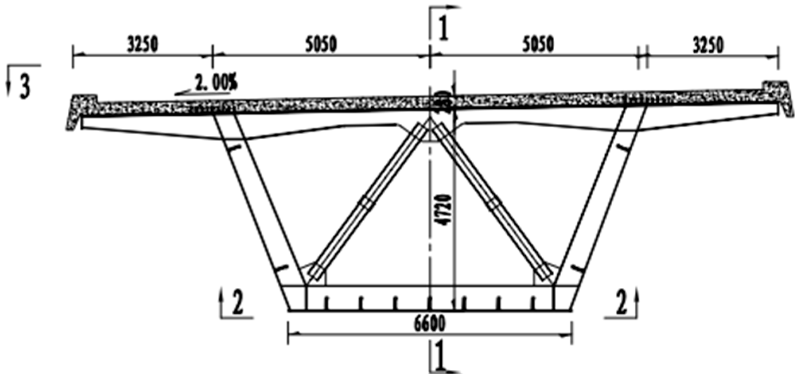
2. Bridge Structural Parameters

This article relies on the project for the incremental launching construction of the main bridge of the Jiaozuo-Xingyang section of the Jiaozuo-Pingdingshan Expressway across the Yellow River. The bridge structure type is a steel–concrete combined girder. Compared to a reinforced concrete girder, a steel–concrete combined girder can reduce structural deadweight, reduce seismic effect, reduce cross-section size, increase the effective use of space, save the molding process and templates, shorten the construction period, and increase the ductility of the girder, etc. Compared to a steel girder, it can reduce the amount of steel used, increase stiffness, and increase stability and integrity. Compared to steel beams, it can reduce the amount of steel, increase stiffness, increase stability and integrity, and enhance the fire resistance and durability of the structure. In recent years, steel–concrete combination beams have been more and more widely used in China’s urban overpass girders and building structures, and are developing in the direction of a large span. The application practice of steel–concrete combined beams in China shows that they have the advantages of both steel and concrete structures, with significant technical and economic benefits and social benefits suitable for the national conditions of China’s capital construction, and are one of the main development directions of future structural systems. The total length of the main bridge is 3656 m, and the span layout is 6 × (6 × 100 m) + 1 × 50 m, with a total of 7 sections. The bridge deck width is 16.55 m, and a 2% unidirectional transverse slope is set on all of them. The cross-section of the main girder is shown in Figure 1. In order to reduce the maximum cantilever length of the main girder and the negative moment at the pivot point, a steel guide beam was set up at the front end of the main girder, the length of the guide beam was 61 m, and the incremental launching arrangement is shown in Figure 2.

3. Finite Element Modeling

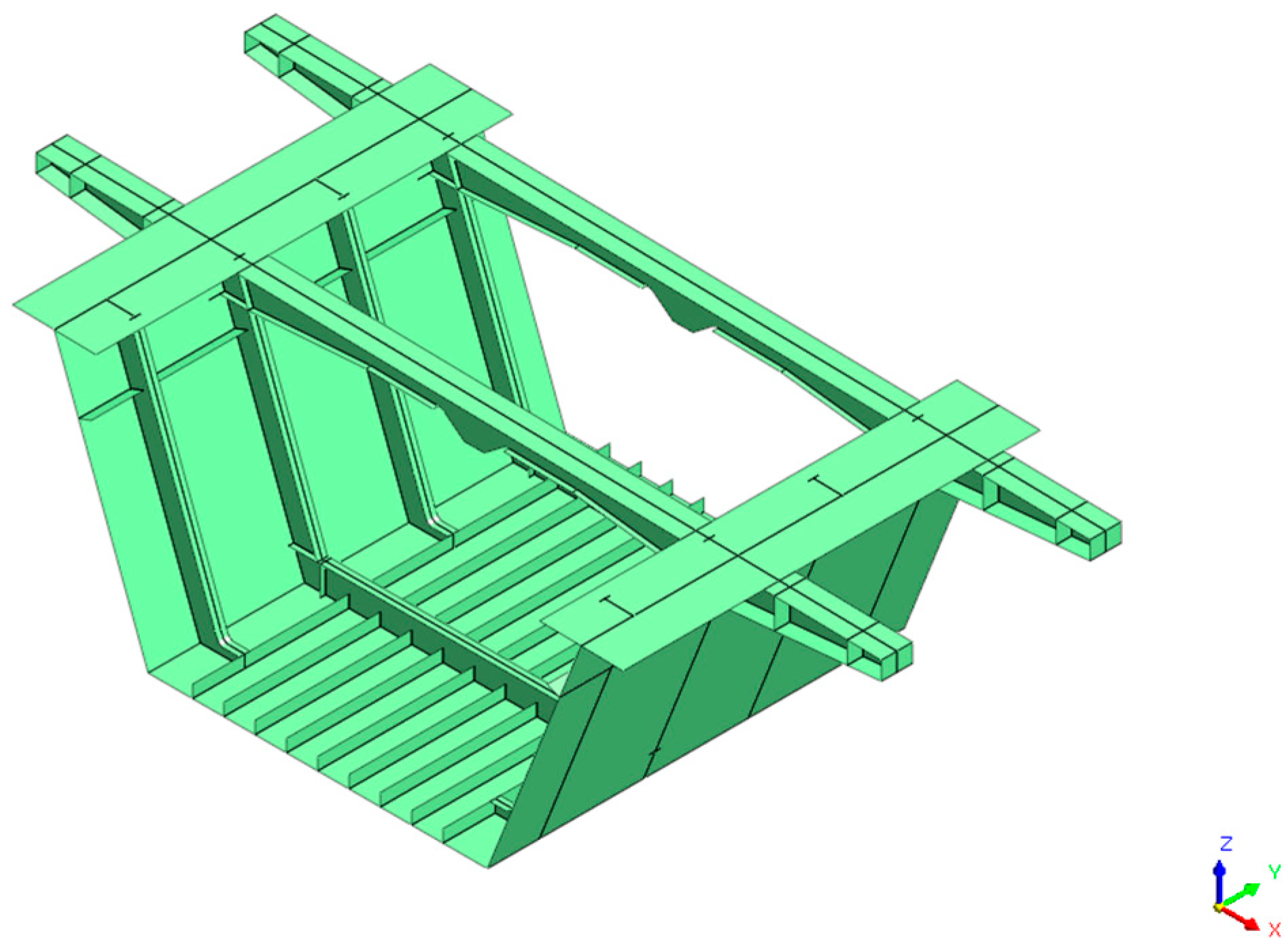
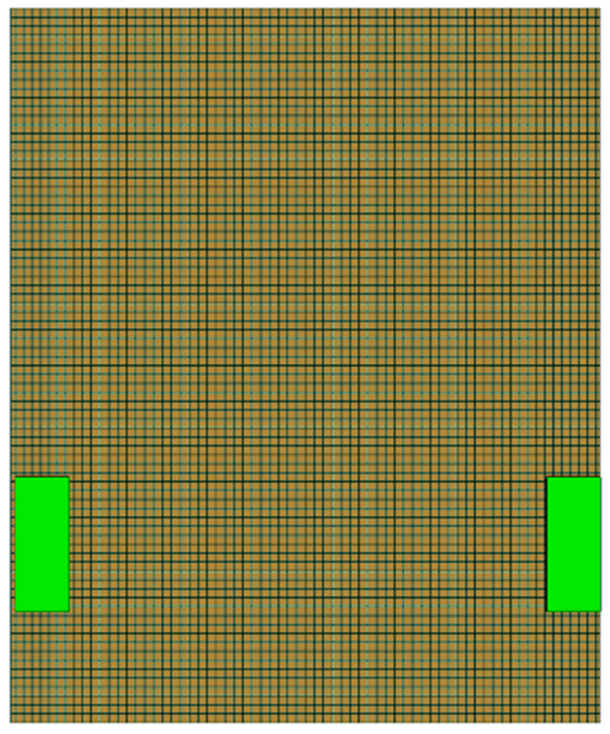
3.1. Module Selection and Meshing

In this paper, the Midas FEA NX finite element analysis software is used to establish a local “beam-shell-solid-contact” finite element model of the steel channel beam under the maximum cantilever condition. The maximum cantilever condition is when the guide beam is about to reach pier 142 and the cantilever length reaches 100 m. The shell unit is selected to model the 8 m long girder section supported by the cantilever root on pier 143 in detail, and the geometric model is shown in Figure 3. The remaining main girders, guide girders, and hollow web truss-type diaphragm are selected to be modeled with beam units, and rigid connections are established in the part where the beam unit meets the shell unit to make their nodes coupled. The rigid connection is shown in Figure 4. Solid units are selected for modeling the pads. The material of the main girder and steel guide beam is Q345qD steel with a density of 7850 kg/m3, a modulus of elasticity of 210 GPa, Poisson’s ratio of 0.3, and the pads are made of rubber pads with a modulus of elasticity of 30 MPa. The overall mesh size of the main beam is 100 mm. The whole beam is divided into 24,379 cells.

3.2. Boundary Condition Simulation

The contact between the steel channel beam base plate and the mat is of the highly accurate face–face discrete cell type, with the steel channel beam base plate as the master face and the top face of the mat as the slave face. The contact form is general contact (only compression and no tension in the normal direction, which can be de-embedded), with no friction in the tangential direction. A constraint is set at each pier in the elevation to constrain its degrees of freedom in x (the transverse bridge direction) and z (the vertical bridge direction).

3.3. Load Simulation

First, gravity is applied to the structure and the acceleration of gravity is taken as −9800 mm/s2. Secondly, the self-weight of the diaphragm as well as the ribbed plate is applied in the form of concentrated loads at the corresponding nodes of the beam unit at magnitudes of −261,995 N (pivot diaphragm), −60,155 N (hollow diaphragm), and −12,057 N (ribbed plate). A multi-scale model of the steel channel beam is shown in Figure 5. The initial position of the pad is shown in Figure 6.

4. Local Stress Analysis

The allowable stress of Q345qD steel is 233 MPa. Observing Figure 7, it can be seen that, under the maximum cantilever condition, the stress level in the contact region between the pads and the steel channel beam is high, which is mainly stressed by the components located in the contact region. Observing the stress cloud (Figure 8) of the components located in the contact region (base plate, web, longitudinal stiffening ribs of the base plate, and hollow web diaphragm system) reveals that the maximum equivalent stress is located at the location of the base plate in direct contact with the pads, with a magnitude of 198.30 MPa. The web is not in direct contact with the pads, but it is located within the direct contact of the pads and has a high stress level with a magnitude of 196.51 MPa due to the deformation coordination. The longitudinal stiffening ribs of the base plate and the transverse bulkhead are still at a certain distance from the pads, and their stresses mainly come from the coordination of deformation, with maximum equivalent stresses of 101.71 MPa and 74.85 MPa, respectively, and the overall stresses being small. The rest of the locations have lower stress levels and a better degree of stress diffusion, and the girder section, as a whole, is in a safe state, which ensures smooth incremental launching construction.

5. Study on Single-Parameter Control of Synchronization in Incremental Launching Construction

The project’s jacking equipment is symmetrically arranged, with one set of jacking devices at each pier, including jacks for the vertical jacking of the beam, jacks to push the beam forward, and jacks to correct the lateral offset, etc. The jacking device is controlled by the center control system. Ideally, the left- and right-side jacks would maintain the same height of vertical jacking and the same distance of travel in the direction of the bridge in each cycle, thus allowing the beam to move forward smoothly. However, in the actual construction process, it is difficult to keep the working status of the left and right jacks at the top of each pier consistent due to errors of the jack control system and sensor system or the difference in the friction force, etc. [29]. When there is a difference between the vertical jacking heights of the left and right jacks, the girder will rotate around the bridge axis, thus generating a deflected load; when there is a difference in the jacking distance between the left and right jacks, the jacking thrust combined force does not coincide with the bridge axis, resulting in the lateral offset of the girder, which causes the contact position to change, leading to changes in the force of the girder, and, as the girder continues to be spliced together side by side, the lateral offsets will be gradually accumulated and even the phenomenon of instability is likely to occur. Therefore, it is necessary to study the phenomenon of jacking desynchronization that occurs during incremental launching construction.

5.1. Stress Changes Due to Unsynchronized Vertical Jacking

The state of unsynchronized vertical jacking under the maximum cantilever condition in jacking construction is simulated by applying forced displacement in the Z direction (vertical bridge direction) to the base of the left pad in the model, and analyzing the stress changes in the steel box girder members under this state. The proposed vertical jacking height differences are: 5 mm, 10 mm, 15 mm, 20 mm, and 25 mm for a comparative analysis.
When there is a difference in the vertical jacking height between the right and left jacks, the girder will rotate around the bridge axis. From Table 1, it can be seen that the base supports the reaction force of the right-side pad (the side with a smaller vertical jacking height) in the occurrence of unsynchronized vertical jacking, the side with the smaller vertical jacking height is subjected to a larger support reaction force, and the size increases with an increase in the jacking height difference. Vertical jacking height difference is shown in Figure 9.
From Figure 10, it can be seen that the maximum equivalent stress values of each steel box girder component increase with the vertical jacking height difference due to the occurrence of the bias load phenomenon. It can also be noticed that there is a difference in the sensitivity of the steel box girder components to unsynchronized vertical jacking. The stress levels in the longitudinal stiff ribs of the base plate and diaphragms increase faster, indicating that are were more sensitive to unsynchronized vertical jacking. In contrast, the unsynchronized vertical jacking between the roof plate and the longitudinal stiffening ribs of the web plate does not have a significant effect on their stress levels due to their long distance from the contact area. The above pattern is consistent with that described in the thirtieth document [30]. The reliability of the model is verified. When the vertical jacking height difference is 15 mm, the overall stress level of the beam is low, and when the height difference reaches 20 mm, the maximum equivalent stress of the base plate reaches 244.45 MPa, which exceeds the permissible stress of Q345qD steel, and is prone to structural instability and damage. Therefore, 15 mm is initially considered as the vertical jacking height difference control threshold for the single-parameter control of jacking synchronization.

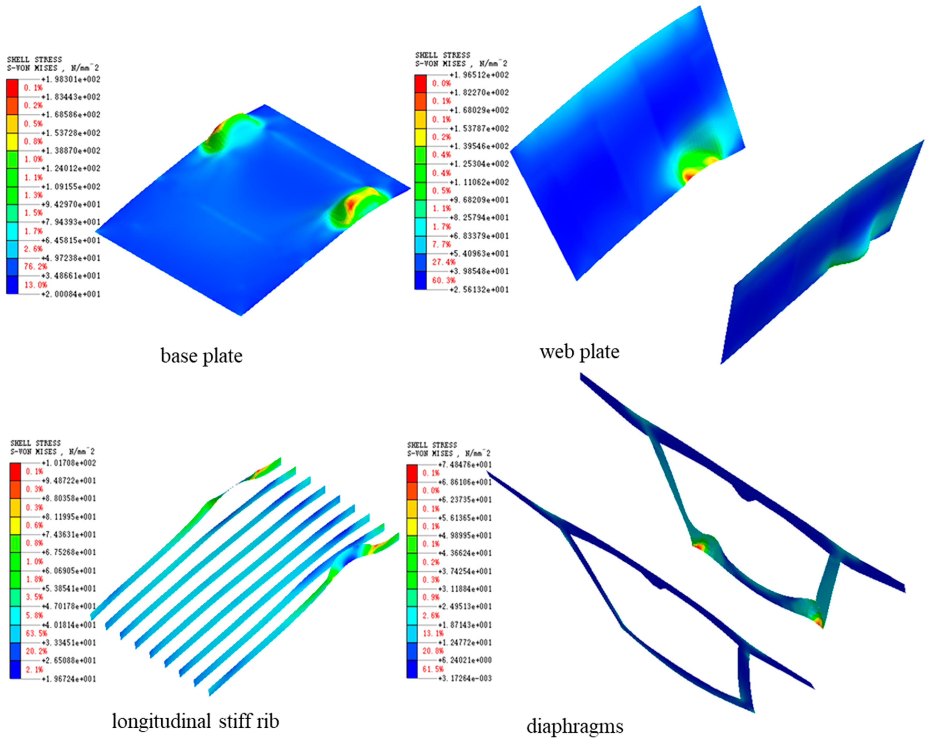
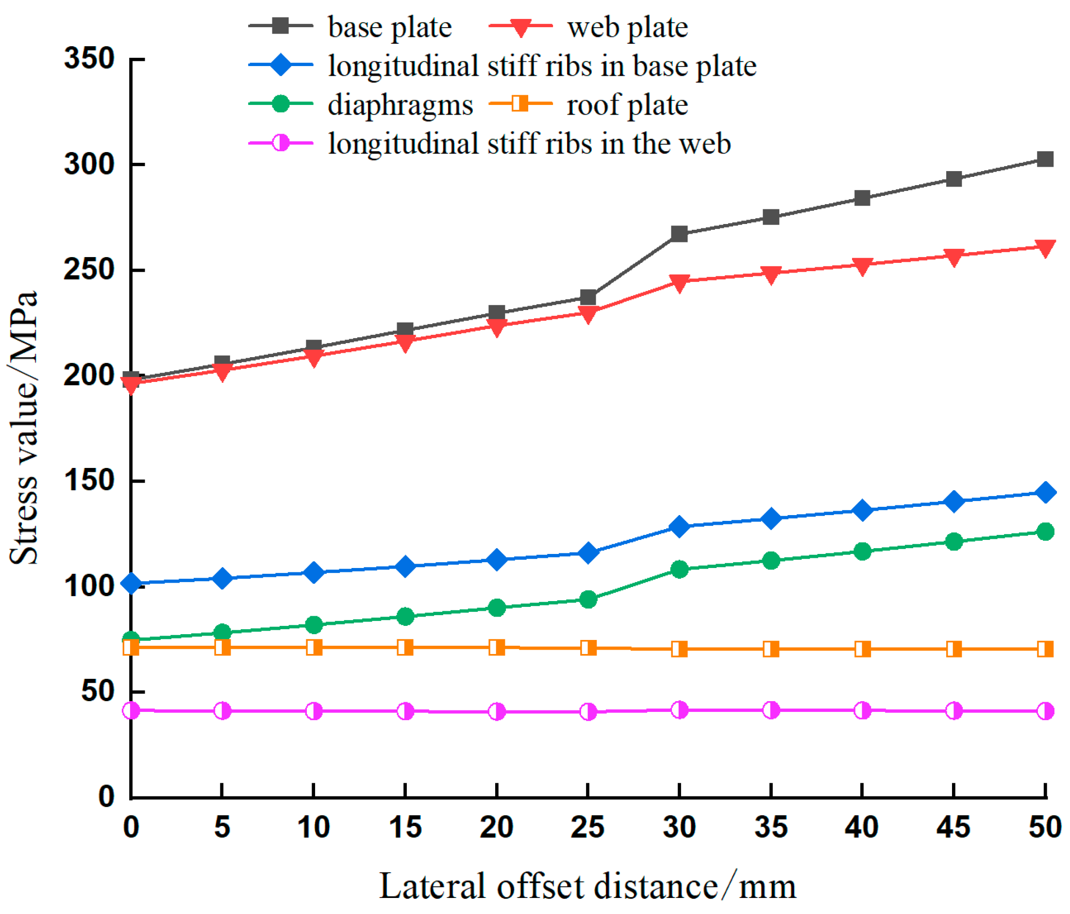
5.2. Stress Changes Due to Lateral Offset

When no lateral offset occurs, the pads are positioned on both sides of the beam axis, symmetrical about the axis. When lateral offset occurs, the contact position will be shifted from side to side. The lateral offset of the beam in incremental launching is simulated by changing the relative position of the pads and the base plate of the steel box girders, and the changes in the local stresses of the main components at lateral offsets of 10 mm, 20 mm, 30 mm, 40 mm, and 50 mm are analyzed, respectively, and the results are shown in Figure 11.
From the figure, it can be seen that, with an increase in the lateral offset distance, the pads on one side are gradually deflected away from the web on that side and close to the outermost longitudinal stiff rib of the base plate. At this time, the base plate and the longitudinal stiff rib of the base plate are involved in more stress, and the maximum equivalent stress and deformation gradually increase. Due to the coordinated deformation of the structure as a whole, the maximum equivalent stresses of the web and the diaphragm are gradually increased. In contrast, the maximum equivalent stresses in the roof plate and longitudinal stiff ribs of the web, which are farther away from the contact region, do not change significantly. When the lateral offset exceeds 25 mm, the pads on one side leave the web. At this time, only the base plate side is located in the direct support area of the pads and the base plate stress increases steeply. When the lateral offset distance is 20 mm, the maximum equivalent stress of the base plate is 229.85 MPa, and when the lateral offset reaches 25 mm, the maximum equivalent stress of the base plate reaches 237.37 MPa, which is more than the permissible stress of steel. As the lateral offset distance continues to increase, the stress level in the base plate may even reach the yield stress of the steel, resulting in the yielding of the plate. Therefore, 20 mm is initially considered as the lateral offset control threshold when considering only a single parameter.

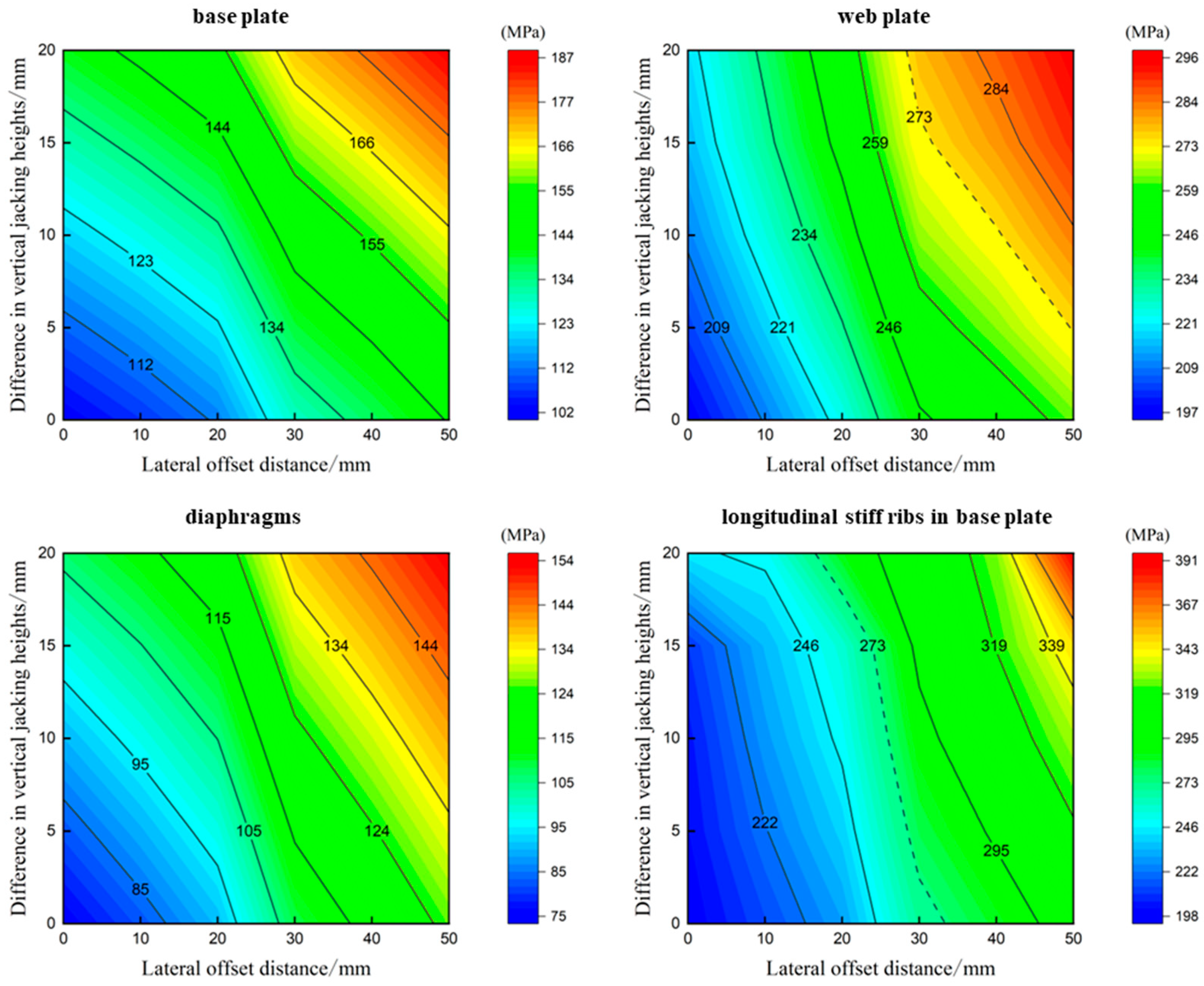
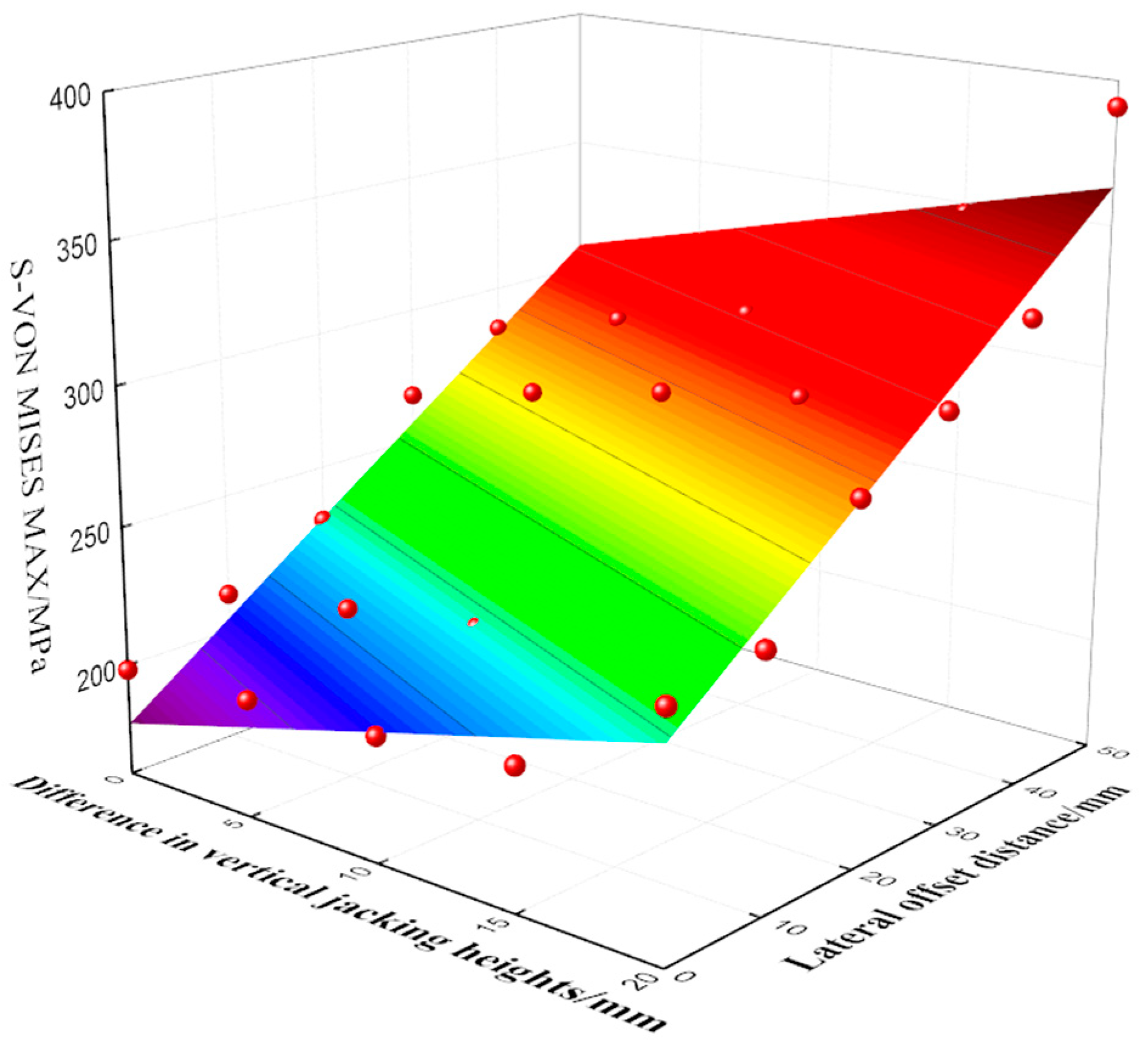
6. Study on Two-Parameter Control of Synchronization in Incremental Launching Construction

According to Wang Biao’s research [31], the probability of the normal operation of jacking equipment in incremental launching construction obeys a normal distribution; as a result, it is highly likely that two unfavorable states, unsynchronized vertical jacking and lateral offset, will occur simultaneously. If the influence of only a single factor is considered, it is easy to set the safety control thresholds to a large extent, which is not conducive to structural safety. To address this problem, based on the above single-parameter-influenced model of steel box girders, a correlation study of two parameters (unsynchronized vertical jacking and lateral offset) for the control of jacking synchronization is carried out. While changing the relative position of the pads to the base of the beam, a forced displacement in the Z-direction is applied to the base of pad on one side to simulate the simultaneous occurrence of the two unfavorable states. The results obtained from the analysis of the variation in the stresses of each main stress member with the vertical jacking height difference and lateral offset distance are shown in Figure 12.
From the figure, it can be seen that the magnitude of the stress increase in each major stress member under the influence of a single parameter is smaller than the magnitude of the stress increase under the combined effect of two parameters. Observing the variation in the maximum equivalent force of the base plate, it can be found that, under the influence of a single parameter, the maximum equivalent force is 229.85 MPa at a lateral offset of 20 mm, and when the vertical jacking height difference is 15 mm, the maximum equivalent stress is 209.97 MPa, none of which exceeds the permissible stress of steel and meets the requirement of single-parameter control. However, under the joint influence of the two parameters, the maximum equivalent stress of the base plate reaches 256.31 MPa, which exceeds the allowable stress of steel. When the lateral offset reaches 50 mm and the vertical jacking height difference reaches 20 mm, the maximum equivalent stress of the base plate reaches 391 MPa, even exceeding the yield stress of steel, and the structure is very easy to be unstable. Therefore, when the two parameters act together, it will exacerbate the stress changes in each stressed member, and setting the control threshold only from the perspective of a single parameter is not enough to ensure the safety of the structure in incremental launching construction; it is necessary to synthesize the effects of the two to set the control threshold.
In order to calculate the two-parameter control threshold, a nonlinear surface is fitted to the maximum equivalent stress value of the beam under the influence of the two parameters. For ease of computation, Z = Z 0 + a x + b y is chosen as the fitted equation, where x represents the vertical jacking height difference and y the lateral offset distance. The fitting results are shown in Figure 13. Solve for Z 0 = 182.71, a = 2.97, b = 2.50. Then, the nonlinear surface fitting equation is:
Z = 182.71 + 2.97 x + 2.50 y
R 2 = 0.99762 , which is very close to 1, suggesting that the fit is valid. The allowable stress of Q345Qd steel is 233 MPa, when Z 233 MPa:
y 1.19 x + 20.06
At this point, the structure is in a safe state and the image of the function is plotted, as shown in Figure 14. The green area in the figure shows the safety range under the two-parameter control of the synchronization of incremental launching construction, and the intersections of the function with the coordinate axes are (16.86, 0), (0, 20.06). In practice, the vertical jacking height difference value can be read directly from the vertical jack controller, while the lateral offset value needs to be further measured manually. Therefore, the vertical jacking height difference control thresholds can be set to 15 mm. After the vertical jacking height difference is read, it is substituted into (2) for calculation to determine the lateral offset control thresholds. For example, when the vertical jacking height difference is 10 mm, the calculated lateral offset value should be less than or equal to 8 mm, so as to realize the dynamic control of lateral offset.

7. Conclusions

(1)
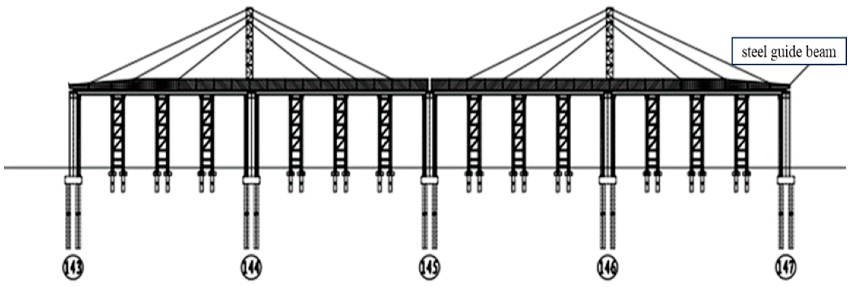
In this paper, the local stresses on the girder segments supported on the top of the piers in the maximum cantilever state were analyzed by establishing a finite element model of the steel box girder in the maximum cantilever state during incremental launching construction. The analysis results indicated that the local force of the steel box girders met the requirements, and the jacking could be carried out smoothly.
(2)
By simulating the unsynchronized vertical jacking and lateral offset occurring during incremental launching construction in the above model, the local stress changes in the girder segments under the separate effects of unsynchronized vertical jacking and lateral offset were analyzed. When unsynchronized vertical jacking occurred, the beam generated a bias load (the side with the smaller jacking height was subjected to a larger reaction force) and the local maximum equivalent force became larger with an increase in the difference in the jacking height. The sensitivities of different stress components to unsynchronized vertical jacking were different, and the diaphragms and longitudinal stiff ribs of the base plate were more sensitive to unsynchronized vertical jacking. When lateral offset occurred, the local maximum equivalent stress occurred in the contact area between the base plate and the pad, and increased with an increase in the lateral offset distance, even approaching the yield stress of the steel and seriously affecting the structural safety. Therefore, thresholds for the synchronization control of incremental launching shall be established and strictly monitored and corrected in a timely manner.
(3)
By calculating the local stresses in the beam when unsynchronized vertical jacking and lateral deflection occurred simultaneously in the beam, it could be found that the beam met the control requirements when the vertical jacking was unsynchronized vertical jacking or when the lateral deflections individually reached a certain value; however, when the two acted together, the local stresses in the beam may still have exceeded the safe range. Against the problem that the single-parameter control of synchronicity misses unfavorable states, this paper proposed the two-parameter control of top thrust synchronization, fitting the maximum equivalent stress under two-parameter co-action, and the permissible stress of Q345qD steel was used as the limit value to obtain the two-parameter control equation of jacking synchronization, determine the control threshold of unsynchronized vertical jacking as 15 mm, and calculate the corresponding control threshold of lateral deflection according to the control equation to realize the dynamic control of lateral deflection.

Author Contributions

Conceptualization, Q.L.; Methodology, H.G.; Software, H.G.; Formal analysis, H.G.; Writing—original draft, H.G.; Writing—review & editing, B.G. All authors have read and agreed to the published version of the manuscript.

Funding

This research received no external funding.

Informed Consent Statement

Not applicable.

Data Availability Statement

The data presented in this study are available on request from the corresponding author. The data are not publicly available due to privacy restrictions.

Conflicts of Interest

The authors declare no conflict of interest.

References

  1. Zhao, R.; Zhang, S. Research status and development trend of bridge jacking method construction. China J. Highw. Transp. 2016, 29, 32–43. [Google Scholar]
  2. Gong, Z. Top thrust weight 9000t continuous steel box girder bridge in Chiapas, Mexico. World Bridges 2004, 3, 27. [Google Scholar]
  3. Shao, H.; Zhou, Y.; Luo, X. Construction of Dijiahe Bridge by Overhead Pushing Method. J. China Railw. Soc. 1979, 2, 63–78. [Google Scholar]
  4. Hua, X.; Cao, L.; Wang, Y. Transient Dynamic Effect Analysis of Incremental Launching Start-Up of Steel Truss Grider Bridge Under Long Cantilever State. Bridge Constr. 2019, 49, 18–22. [Google Scholar]
  5. Zhang, M.; Xin, Y.; Hu, T. Intelligent Monitoring and Analysis of Incremental Launching Construction of Precast Frame Bridge. Ind. Constr. 2022, 52, 106–110. [Google Scholar]
  6. Xiong, B.; Yu, Z.; Ma, M. Application of BIM technology in the jacking construction of steel box girder bridge. Build. Struct. 2022, 52, 1968–1972. [Google Scholar]
  7. Zhou, J.; Li, X.; Wu, Y. Incremental Launching Construction Method for Long-Span Light Rail Bridge with Main Grider Composed of Steel Boxes and Concrete Slabs. World Bridges 2021, 49, 64–71. [Google Scholar]
  8. Chen, W. Monitoring on Incremental Launching Construction of Prestressed Concrete Continuous Box Girder. Railw. Eng. 2018, 58, 53–57. [Google Scholar]
  9. Yang, W.; Que, S.; Chu, M. Rotation Adaptive Control Method for Incremental Launching Construction of Main Girder in Bridge with Complex Vertical Curves. Bridge Constr. 2022, 52, 53–59. [Google Scholar]
  10. Li, C.; Zhou, Q.; Dong, C. Fabrication Configuration and Unstressed Geometry Achievement of Beam Segment of Incrementally Launched Steel Box Girder. J. Highw. Transp. Res. Dev. 2018, 35, 40–48. [Google Scholar]
  11. Chen, X.; Li, J.; Yang, H. Steel Truss Girder Linear and Stress Control Based on Improved Equipment Pushing Constructio. J. Civ. Eng. Manag. 2018, 35, 43–47. [Google Scholar]
  12. Dong, C.; Li, C.; Zhang, Y. Single-step modulus search and composition method for determining the scheme of support elevation adjustment during girder launching with vertically varied curvatures. China Civ. Eng. J. 2015, 48, 101–111. [Google Scholar]
  13. Cui, M. Research on Control Technology of Steel Box Girder Incremental Launching Construction; North China University of Water Resources and Electric Power: Zhengzhou, China, 2020. [Google Scholar]
  14. Wang, D.; Zhang, Z.; Huang, W. Local force analysis and control in incremental launching process of wide steel box beams. J. Zhejiang Univ. Technol. 2023, 51, 248–254. [Google Scholar]
  15. Xu, W.; He, P.; Lu, H. Prediction of Local Maximum Stress of Ultra Wide Steel Box Girder during Incremental Launching Construction Process Based on GSA-SVR. J. Highw. Transp. Res. Dev. 2021, 38, 41–47. [Google Scholar]
  16. Tian, Z.; Chen, Y.; Zhao, L. Local contact analysis and improvement measures of continuous steel girder incremental launchin. J. Chang. Univ. 2012, 32, 44–50. [Google Scholar]
  17. Wang, H.-J.; Liu, H.-Z.; Wang, Z.-S.; Zou, Y.; Wei, H. Incremental launching construction method for open steel box girder. J. Shenyang Univ. Technol. 2016, 38, 337–343. [Google Scholar]
  18. Markovic, N.; Kovacevic, S. Influence of patch load length on plate girders. Part I: Experimental research. J. Constr. Steel Res. 2019, 157, 207–228. [Google Scholar] [CrossRef]
  19. Viet-Hung, T.; Papazafeiropoulos, G.; Quang-Viet, V.; Pham, V.-T.; Kong, Z. Predicting the patch load resistance of stiffened plate girders using machine learning algorithms. Ocean. Eng. 2021, 240, 109886. [Google Scholar]
  20. Yu, H. Stress and Lateral Displacement Test of Highway Box Girder During Incremental Pushing Process. Highw. Eng. 2019, 44, 198–202. [Google Scholar]
  21. Li, X.; Zhao, R.; Xu, T. Testing and statistical analysis of lateral offsets in box girder step launching construction. Tunn. Rail Transit 2015, 2, 33–35+44+66. [Google Scholar]
  22. Li, L.; Liu, Y.; Wang, S. Research on Construction Limit and Deviation Correction Technology of Concrete Continuous Box Girder Jacking. Build. Technol. Dev. 2018, 45, 44–45. [Google Scholar]
  23. Xu, S. A New Method Using Two—Point Limit for Jacking Construction of Curved Concrete Box Girder. J. Railw. Eng. Soc. 2014, 5, 53–58. [Google Scholar]
  24. Li, C.; Chen, Z.; Dong, C. Analysis on Local Stress of Wide Steel Box Beam Constructed by Transverse Four—slide Walking—type Incremental Launching Method. J. Highw. Transp. Res. Dev. 2019, 36, 72–79. [Google Scholar]
  25. Zhu, L.; Tang, J.; Xing, S. Effect of Lateral offset on Force State of Prestressed Concrete Trough Girders with Asymmetric Cross-Section. J. Southwest Jiaotong Univ. 2019, 54, 1155–1161. [Google Scholar]
  26. Wang, J.; Chen, S.; Chen, S. Analysis of the Influence of Axis Deviation on the Stress of Multi-span Steel Truss Girder during Pushing Construction. Railw. Stand. Des. 2020, 64, 86–90. [Google Scholar]
  27. Kuang, S. Risk evaluation and analysis of continuous steel box girder jacking construction. Build. Struct. 2023, 53, 2310–2313. [Google Scholar]
  28. Zhu, L.; Chen, Q.; Wu, B. Research on two parameters control and local stress of walking-type incremental launching wide steel box girder. Build. Struct. 2021, 51, 934–939. [Google Scholar]
  29. He, Y. Structural Behavior of Continuous Steel Box Girder Bridges during Stepwise Incremental Launching Construction. Master’s Thesis, Chongqing Jiaotong University, Chongqing, China, 2017. [Google Scholar]
  30. Xie, Q. An Analytical Study of Local Stresses on Steel Box Girders by Walk-Behind Incremental Launching Construction Process. Ph.D. Thesis, Southwest Jiaotong University, Chengdu, China, 2015. [Google Scholar]
  31. Wang, B. Research on the Causes of Lateral Deviation of Steel-Hybrid Girder Incremental Launching and Countermeasures for Deviation Correction. Ph.D. Thesis, Southwest Jiaotong University, Chengdu, China, 2015. [Google Scholar]
Figure 1. Main beam cross-section.
Applsci 13 12074 g001
Figure 2. Incremental launching arrangement.
Applsci 13 12074 g002
Figure 3. Main beam geometry model.
Applsci 13 12074 g003
Figure 4. Rigid connection with nodal coupling.
Applsci 13 12074 g004
Figure 5. Multi-scale modeling of main beams.
Applsci 13 12074 g005
Figure 6. Contact setup.
Applsci 13 12074 g006
Figure 7. Nephogram of the overall force on the main girder segments.
Applsci 13 12074 g007
Figure 8. Stress nephogram of major components.
Applsci 13 12074 g008
Figure 9. Schematic diagram of vertical jacking height difference.
Applsci 13 12074 g009
Figure 10. Effect of unsynchronized vertical jacking on stresses.
Applsci 13 12074 g010
Figure 11. Effect of lateral offset on stress.
Applsci 13 12074 g011
Figure 12. Stress contour plots of major components under two-parameter action.
Applsci 13 12074 g012
Figure 13. Maximum equivalent stress fitting results under two-parameter effects.
Applsci 13 12074 g013
Figure 14. Dual-parameter dynamic control range.
Applsci 13 12074 g014
Table 1. Change in support force on the lower side of vertical jacking.
Difference in Vertical Jacking Heights/mm0510152025
Reaction force/KN1368.121434.251492.391537.881563.821570.09
Disclaimer/Publisher’s Note: The statements, opinions and data contained in all publications are solely those of the individual author(s) and contributor(s) and not of MDPI and/or the editor(s). MDPI and/or the editor(s) disclaim responsibility for any injury to people or property resulting from any ideas, methods, instructions or products referred to in the content.

