Article

Coupled Thermo-Mechanical Phase-Field Modeling to Simulate the Crack Evolution of Defective Ceramic Materials under Flame Thermal Shock

School of Applied Science, Taiyuan University of Science and Technology, Taiyuan 030024, China
*
Author to whom correspondence should be addressed.
Appl. Sci. 2023, 13(23), 12633; https://doi.org/10.3390/app132312633
Submission received: 4 November 2023 / Revised: 19 November 2023 / Accepted: 22 November 2023 / Published: 23 November 2023

Abstract

:
Crack propagation in ceramics is a highly quick, complex, and nonlinear process that occurs under thermal shock. It is challenging to directly observe the evolution process of cracks in experiments due to the high speed and unpredictability of crack propagation. Based on the phase-field fracture method, a phase-field numerical model combined with thermal and mechanical damage is established to analyze the crack propagation path, velocity, and morphology of pre-cracked ceramic plates under flame thermal shock loading. This research primarily focuses on the impact of prefabricated crack angle and length on crack propagation. According to the findings of the numerical simulation, ceramic plates with varied prefabricated crack angles are loaded via flame thermal shock, and thermal stress is caused by the rapid rise in the temperature difference between the top edge and the inside of the ceramic plate. Hence, the crack propagation rate seems to be quick at first, and then, slows down when the wing-like cracks at the crack tips spread to both ends. The crack tip on the side closer to the flame thermal loading is more likely to generate wing-shaped cracks as the length of the pre-existing crack increases. However, the crack tip on the side further away from the flame thermal loading exhibits the reverse tendency. The complex evolution process of crack initiation, propagation, and coalescence in ceramic materials brought on by flame thermal shock can be predicted by the thermo-mechanical coupled phase-field model, which is a valuable reference for designing and optimizing the thermal shock resistance and mechanical failure prediction of ceramic materials.

1. Introduction

Ceramic materials are extensively used in the aerospace field because they have high melting points, high hardness, low density, superior tribology, and remarkable stability at high temperatures [1]. For instance, they are adopted in gas turbine engines [2], thermal protection materials for nose tips [3], nuclear power generation [4], and the wing leading edges of hypersonic vehicles [5]. Ceramics can be applied to create high-temperature components, most typically thermal barrier coatings, such as turbine blades and combustion chamber linings in aerospace engines [6]. On the other hand, brittle materials, like ceramics, frequently have weak thermal shock resistance, leaving them vulnerable to thermal shock failure [7,8,9] in situations with fast temperature changes. Thermal shock failure occurs as a result of temperature gradients inside ceramic materials. Various parts are subjected to different degrees of thermal stress, which causes internal stress concentration and forms cracks. Therefore, it is critical to comprehend the initiation and propagation of cracks in ceramic materials under thermal shock, as well as to evaluate and enhance the thermal shock resistance to ensure the materials’ functioning in a high-temperature environment.
Scholars have recently used a range of experiments, theories, and numerical approaches to investigate the thermal shock crack behavior of ceramic materials and assess their thermal shock resistance. For example, Li et al. [10] employed a high-speed imaging technique to analyze the difference in crack growth under cold and thermal shock. Su et al. [11] examined the ablation mechanisms of Ti3SiC2 ceramic in a 1600 °C nitrogen plasma flame. Liu et al. [12] investigated the influence of surface brittle-to-ductile transition on the high-temperature thermal shock resistance of Al2O3 ceramics. Ceramic materials are still the subject of a lot of research [13,14,15,16,17]. However, the initiation and propagation of cracks in ceramic materials under thermal shock are incredibly rapid and complicated. In many cases, only the thermal shock crack pattern and fracture surface following thermal shock can be seen due to the limitations of monitoring technology. Consequently, crack initiation and propagation under thermal shock have been extensively studied using numerical simulation methods (such as the finite element method [18], extended finite element method [19], discrete element method [20], etc.). Giannakeas et al. [21] adopted bond-based peridynamics and FEM to simulate thermal shock cracking in ceramics. Cao et al. [22] carried out simulated analysis and the optimization of SiC ceramics via the laser preheating of RSM. Dong et al. [23] utilized the extended finite element method (XFEM) to forecast the development of cracks in ceramics under various loading conditions. However, the aforementioned numerical simulation methods have several drawbacks in studying the crack propagation behavior of brittle materials, such as crack branching and multi-cracking, especially in three-dimensional issues.
The phase-field method, which is based on the energy variational principle [24] of brittle fractures, has lately gained popularity for simulating the fracture of brittle materials. Bourdin et al. [25] described the crack-cracking process by introducing a continuous phase-field variable (0–1). Miehe et al. [26,27,28] made significant contributions to the development of phase fields, as well. Additionally, Wu et al. [29,30] suggested a phase-field regularized cohesive region model that is insensitive to the length-scale parameter based on the phase-field method. In comparison to other models, the phase-field model does not require unique failure criteria to detect when/where cracks nucleate, propagate, branch, merge, etc. It may considerably reduce the computational complexity by simulating the whole solid process, from crack initiation through propagation to fracture. The phase-field fracture model is widely employed in a variety of fracture problems, including brittle fracture [31], hyperelastic fracture [32,33], multi-physical fracture [34,35], etc.
Thermal shock coupled fracture is also a typical problem in the successful application of phase-field models. For example, Miehe et al. [36] developed a fully coupled thermo-mechanical phase-field model for brittle fracture and studied the thermal shock-induced crack of glass ribbon and solid brick. Li et al. [37] explored the thermal shock fracture of ceramic materials with temperature variation based on thermodynamically linked phase-field modeling. Ceramic materials are prone to producing pores and micro-cracks in preparation and service, which will affect their thermal shock resistance. Investigations on the effect of defects on crack growth under hot shock are still rare. Thus far, the relevant influence mechanism has not been particularly clear. In addition, there are few simulations related to hot shock crack propagation, with most focusing on cold shock crack propagation [16,38]. In this paper, the fracture behavior of ceramic materials containing flaws under flame thermal shock is studied using the thermo-mechanical coupled phase-field model.
This paper is arranged as follows. Section 2 develops a thermodynamically consistent phase-field model of thermoelastic brittle fracture from the fundamentals of thermodynamics. Section 3 presents the material parameters, geometry, and boundary conditions of the model. Two instances of research on the effect of changes in the angle and length of prefabricated cracks under flame thermal shock are displayed in Section 4. The conclusions of this paper are drawn in Section 5.

2. Coupled Thermo-Mechanical Phase-Field Modeling

The thermal cracking process of brittle materials, like ceramics, is the main topic of this paper. With the effective stress theory [39,40] and thermal strain taken into account, the mechanical field is coupled with the hygrothermal field. The main field variables in the thermodynamic coupling problem include the temperature field T ( x , t ) , displacement field u ( x , t ) , and damage field d ( x , t ) .

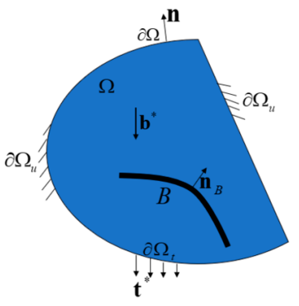
2.1. Energy Imbalance

According to the rules of thermodynamics, i.e., the Clausius–Duhem inequality, the local dissipation energy of power produced by macroscopic and microscopic forces is considered for this thermodynamic coupling problem [35]:
D = σ : ε ˙ + K d ˙ + H d ˙ ρ ( ψ ˙ + T ˙ η ) 1 T T q 0
where σ and ε denote the Cauchy stress tensor and strain, respectively; ψ and η represent the Helmholtz free energy and entropy; K is the internal micro-force; ρ represents the density; and H is the micro-traction on the crack surface.
Elastic energy ψ e , fracture energy ψ c , and thermal energy ψ T make up the Helmholtz free energy.
ψ = ψ ( ε , d , d , T ) = ψ e ( ε , d , T ) + ψ c ( d , d , T ) + ψ T ( T )
For the above free energy equation, the rate of change of free energy is as follows.
ψ ˙ = ψ ˙ e + ψ ˙ c + ψ ˙ T
{ ψ ˙ e = ψ e ε : ε ˙ + ψ e d d ˙ + ψ e T T ˙ ψ ˙ c = ψ c d d ˙ + ψ c ( d ) d ˙ + ψ c T T ˙ ψ ˙ T = ψ T T T ˙
We can obtain the below equation after substituting Equation (4) into Equation (3).
ψ ˙ = ψ e ε : ε ˙ + ( ψ e d + ψ c d ) d ˙ + ψ c ( d ) d ˙ + ( ψ e T + ψ c T + ψ T T ) T ˙
It can be rewritten as follows by taking Equation (5) into the Clausius–Duhem Inequality (1).
( σ ρ ψ ε ) : ε ˙ + ( K ρ ψ d ) d ˙ + ( H ρ ψ ( d ) ) d ˙ ( ρ η + ρ ψ T ) T ˙ 1 T T q 0
It is important to note Inequality (6) needs to meet the thermodynamic processes in any case. As a result, the coefficients of the dissipative terms are not negative, whereas the coefficients of the non-dissipative terms must be zero. According to Coleman-Noll [41], the thermoelastic constitutive relation is depicted below.
{ σ = ρ ψ ε = ρ ψ e ε H = ρ ψ ( d ) = ρ ψ c ( d ) K = ρ ψ d = ρ ψ e d + ρ ψ c d η = ψ T
The rest of the dissipation inequality is also known as the heat conduction inequality.
T q 0

2.2. Damage

In the absence of body force, the linear momentum balance equation can be expressed as follows.
σ = 0
where denotes the divergence operator. The total strain ε can be divided into the elastic strain ε e and the thermal strain ε t .
ε = ε e + ε t = s u : = 1 2 ( u + T u )
The thermal strain ε t should satisfy the linear expansion law.
ε t = α t ( T T 0 ) I
where α t and T 0 represent the coefficient of thermal expansion and initial temperature, respectively. The total elastic free energy density of the undamaged solid is shown below.
ψ e = 1 2 ε e : e : ε e = λ 2 ( tr ε e ) 2 + μ tr ( ε e 2 )
The elastic strain energy density additively decomposes into a positive (tensile) part ψ e + and a negative (compressive) part ψ e when only the tensile part is affected by the degradation function:
ψ e = ψ e + f ( d ) ψ e +
where f ( d ) represents the energy degeneracy function with the following conditions.
f ( d ) [ 0 , 1 ] , f ( 0 ) = 1 , f ( 1 ) = 0 ; f ( d ) < 0 , f ( 1 ) = 0
Only the tensile part contributes to the fracture in this method. Thus, the stress tensor can be further written as follows.
σ = ψ e ε = f ( d ) ψ e + ε + ψ e ε = f ( d ) σ + + σ
The elastic energy degradation function f ( d ) proposed by Wu and Nguyan [42] is used to make the phase-field model insensitive to crack length scale parameters.
f ( d ) = ( 1 d ) 2 ( 1 d ) 2 + a 1 d ( 1 + a 2 d + a 3 d 2 )
In the equation, a 1 = 4 l c h π 0 , a 2 = 1 2 , and a 3 = 0 represent the cohesive nature of the fracture in the process zone. Moreover, l c h = E G c σ u 2 represents Irwin’s length, which is used to measure the size of the fracture process zone. The behavior of the material becomes increasingly brittle as the length scale decreases. Parameters a 2 and a 3 are adopted to adjust different softening curves [29].
We need to apply an irreversible condition, the history strain field [27], to stop the crack from healing:
{ ψ e + 0 , ˙ 0 , ˙ ( ψ e + ) = 0 = max { max t [ 0 , τ ] ψ e + ( ε e , t ) , ψ t h }
where ψ t h is the damage threshold.
ψ t h = σ u 2 2 E
In this equation, σ u and E represent the strength and modulus of elasticity of the material, respectively.

2.3. Considering the Temperature-Dependent Phase-Field Fracture Model

As seen in Figure 1, the external boundary of a cracked solid Ω is represented by Ω , and the crack zone is marked by Γ . As per the Griffith theory of fracture mechanics, the following equation expresses the total fracture energy.
Ψ c = Γ G c ( T ) d A = Ω G c ( T ) γ ( d , d ) d V
Miehe et al. [27] and Wu et al. [29] used the volumetric integral rather than the surface integral to estimate the fracture energy. The crack surface density function γ is written as follows.
γ ( d , d ) = 1 c 0 ( 1 0 ω ( d ) + 0 | d | 2 ) , c 0 = 4 0 1 ω ( β ) d β
The above equation characterizes the evolution of phase-field cracks using a geometric function with the following properties:
ω ( d ) [ 0 , 1 ] , ω ( 0 ) = 0 , ω ( 1 ) = 1 ; ω ( d ) > 0
where 0 is the length scale parameter of a regularized sharp crack, which is related to the width of the diffusion crack And c 0 > 0 represents the scaling parameter [27,29].
The momentum balance equation of the micro force is illustrated below for quasi-static fracture, assuming negligible micro-inertia.
H = K
The governing equation of the phase field can be yielded by combining the micro-force balance Equation (22) with the fracture energy Equation (19).
G c c 0 0 ω ( d ) Y 2 G c 0 c 0 2 d = 0
where Y is the driving force of the phase field, which is expressed as follows.
Y = ψ e d = f ( d )
Consequently, the governing equation of the phase field can be further simplified as shown below.
G c π 0 ( 2 2 d ) + f ( d ) = 0
In thermo-mechanical coupling problems, the temperature variation is significant. Consequently, the influence of temperature close to the crack tip cannot be overlooked when it comes to crack propagation. Therefore, the temperature dependence of the critical energy release rate G c needs to be considered. According to the research of Kitamura et al. [43] and Bayoumi et al. [44], the temperature dependence of the critical energy release rate G c can be described as follows for brittle and quasi-brittle materials:
G c = G c 0 [ 1 b 1 T T r e f T m a x + b 2 ( T T r e f T m a x ) 2 ]
where T r e f and T m a x denote the reference temperature and the maximum temperature, respectively; b 1 and b 2 represent constant model parameters; and G c 0 represents the value of G c at the reference temperature T r e f .
The temperature dependence of material properties affects not only the elastic performance, but also the fracture behavior. Hence, the elastic modulus E, the critical energy release rate G c , and material strength are all thought to be temperature-dependent [45].
E ( θ ) = ϕ 1 ( θ ) E 0 , G c ( θ ) = ϕ 2 ( θ ) G c 0 , σ u ( θ ) = ϕ 3 ( θ ) σ u 0
In the above equation, ϕ 1 , ϕ 2 , and ϕ 3 are related to the temperature degradation function. Then, l c h is as follows.
l c h : = E G c σ u 2 = β l ( θ ) l c h 0 with β l ( θ ) = ϕ 1 ( θ ) ϕ 2 ( θ ) ϕ 3 2 ( θ )
Consequently, a 1 in Equation (16) is presented as below.
a 1 ( θ ) = β l ( θ ) 4 l c h 0 π 0

2.4. Heat Conduction

The following is the energy balance equation, which accounts for the thermal diffusion and the power generated by the microscopic and macroscopic forces [46].
ρ e ˙ = σ : ε ˙ + K d ˙ + H d ˙ q + Q
We can the following based on the given relation e = ψ + T η .
e ˙ = ψ ˙ + T ˙ η + T η ˙
According to the Helmholtz free energy ψ = ψ ( ε , d , d , T ) and the constitutive relationship given by Equation (7), we can obtain the following expression.
ψ ˙ = 1 ρ ( σ : ε ˙ + K d ˙ + H d ˙ ρ T ˙ η )
Combining Equations (31) and (32) yields the following.
ρ e ˙ = σ : ε ˙ + K d ˙ + H d ˙ + ρ T η ˙
We can obtain the following conclusion by comparing Equations (30) and (33).
ρ T η ˙ = q + Q
Based on Equation (7), η ( ε , d , d , T ) = ψ T , we obtain the following equation for a specific entropy rate.
η ˙ = ( 2 ψ T ε : ε ˙ + 2 ψ T d d ˙ + 2 ψ T ( d ) d ˙ + 2 ψ T 2 T ˙ ) = 1 ρ ( σ T : ε ˙ + K T d ˙ + H T d ˙ ρ η T T ˙ )
We consider that Fourier’s law through the inequality relation in Equation (8) automatically satisfies the following equation:
q = k ( d ) T
where k ( d ) represents the phase-field-influenced degraded thermal conductivity and is indicated as follows.
k ( d ) = g ( d ) k 0
In the above equation, k 0 represents the thermal conductivity of the undamaged material, and g ( d ) denotes the thermal degradation function that causes the absence of heat flux on the crack. We may construct the following equation by combining Equations (34) and (35).
T ( σ T : ε ˙ + K T d ˙ + H T d ˙ ρ η T T ˙ ) = k ( d ) 2 T + Q
The specific heat is defined as follows.
c = T η T
Consequently, the following is the complete form of the heat equation.
ρ c T ˙ = k ( d ) 2 T + T ( σ T : ε ˙ + K T d ˙ + H T d ˙ ) + Q
Equation (40) can degenerate into the standard heat conduction equation for thermal conduction with an internal heat source. In this case, we apply the formula for quasi-static crack extension, where the transient coupling terms ε ˙ and d ˙ vanish. Hence, the heat equation takes the following form.
ρ c T ˙ = k ( d ) 2 T + Q

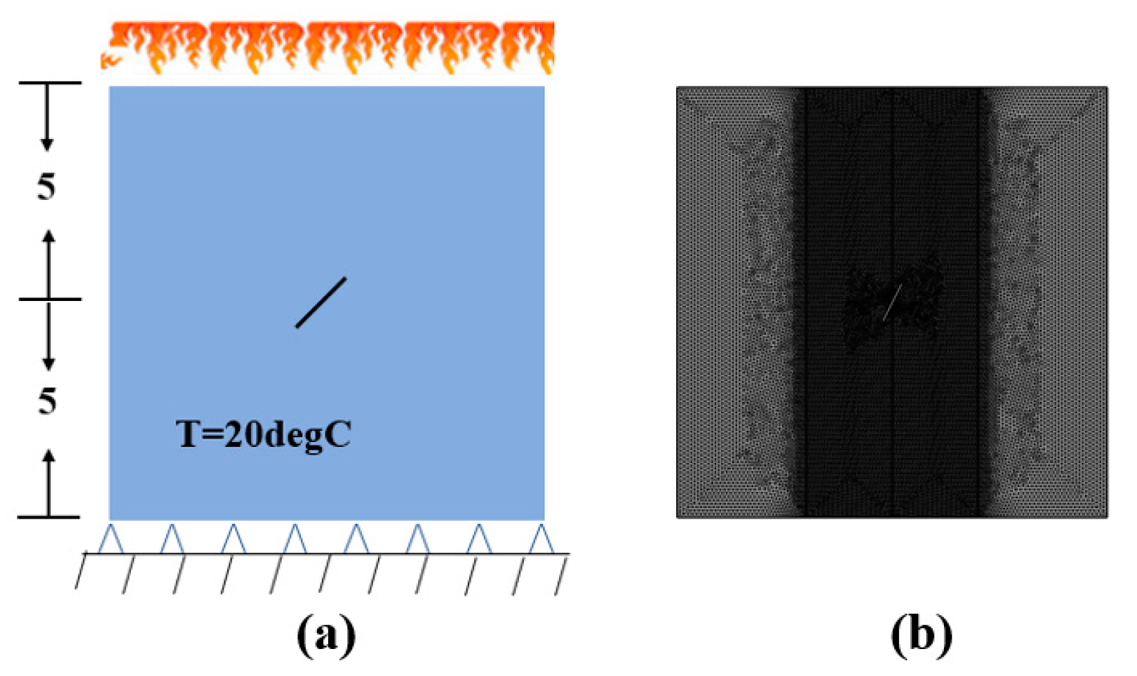
3. Finite Element Modeling

In this section, a numerical simulation based on thermo-mechanical phase-field coupling modeling will be conducted to investigate the influence of flame thermal shock on the behavior of pre-existing cracks in ceramic plates (Figure 2). The proposed model is implemented in the software COMSOL Multiphysics 5.5. The implementations in COMSOL can much more easily to be extended to problems with more fields than those in other software [47], because only the governing equations in strong form are needed in COMSOL. Regarding thermo-mechanical problems, three basic modules, i.e., the Solid Mechanics Module, Poisson’s Equation Module, and Heat Transfer in Solid Module, can be adopted to solve the displacement u , the crack phase field d, and the temperature T. We employ a staggered scheme to solve the coupled system of equations. The difference between the staggered scheme and monolithic scheme is discussed in reference [48].
We propose two numerical simulation schemes to validate the predictive capability of the model. First, we assess the influence of initial crack angle on crack propagation. We can simulate the crack propagation under flame thermal shock by setting different angles. We can study the effect of angle variation on crack propagation behavior by observing the propagation path and rate of the crack. Second, we evaluate the influence of previous crack length on crack propagation. We may examine the response of crack propagation by varying the length of the pre-existing crack. We can evaluate the impact of the pre-existing crack length on crack propagation behavior by comparing the characteristics of crack propagation at different lengths.
The loading conditions, sample dimensions, and boundary conditions for the ceramic plate are depicted in 0. The ceramic specimen is composed of high-purity ceramic (99.5% Al2O3) and has a rectangular shape with a side length of 10 mm. Horizontal and vertical displacements are restricted by the lower boundary. An inward heat flux q 0 = 2 , 000 , 000 ( W / m 2 ) is applied to the upper boundary. The temperature T 0 = 20   ° C is kept constant over the entire ceramic (including the crack surface). The mechanical parameters of the ceramic plate are displayed in Table 1. The triangular element is used to mesh the geometry model, and the size of the mesh of the crack is b 0 = 0.0001   m m . The initial crack width is W = 0.05   mm and the length is L = 1   mm . We investigate the influence of different initial crack angles on crack propagation by changing the initial crack angle (0°, 26.6°, 45°, 63.4°, and 90°). In the simulation, we apply free triangular mesh elements with a minimum element size of h = 0.005 mm. We discovered that local refinement of the mesh elements in the crack propagation region cloud produced more accurate results during the study.

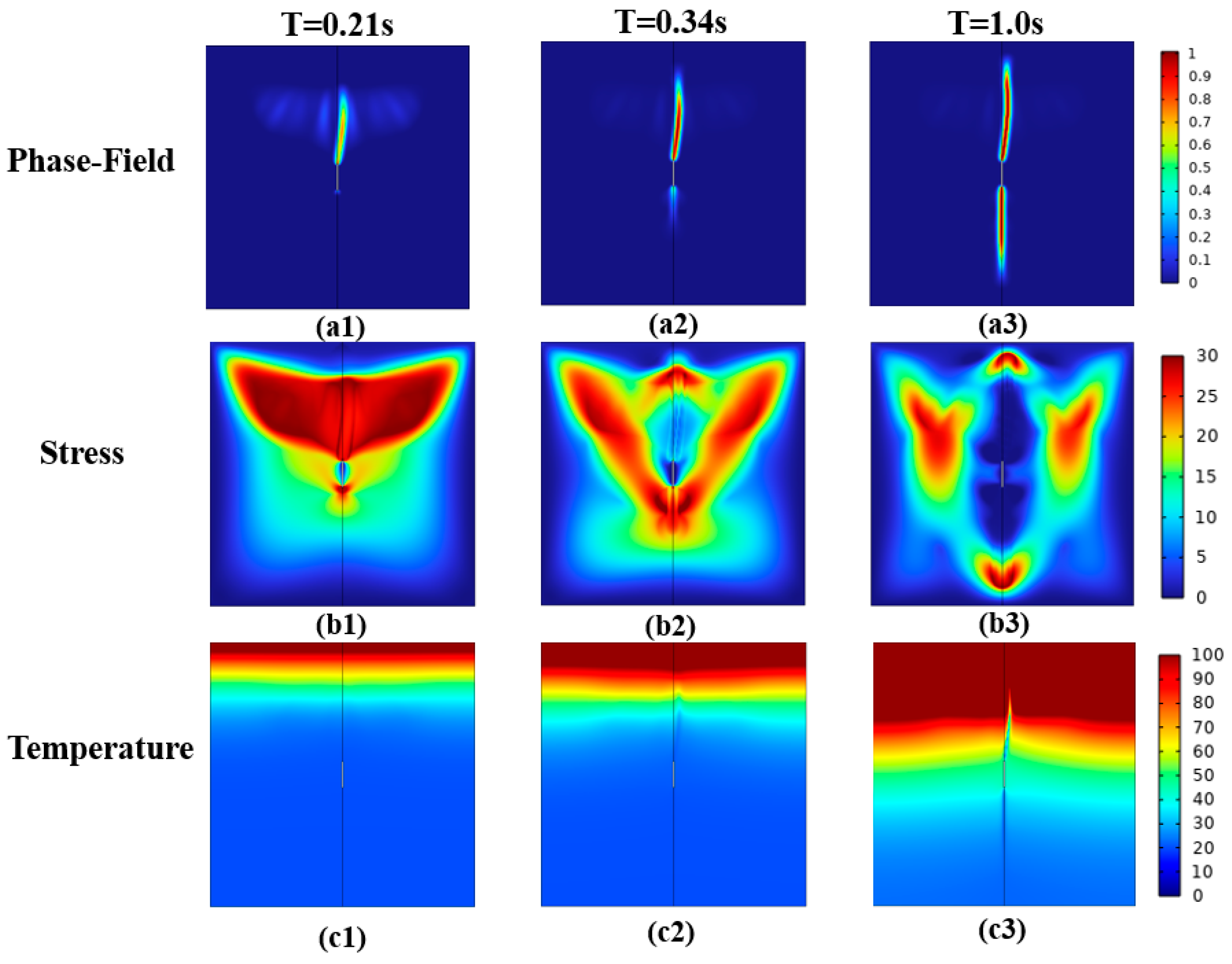
4. Results and Discussion

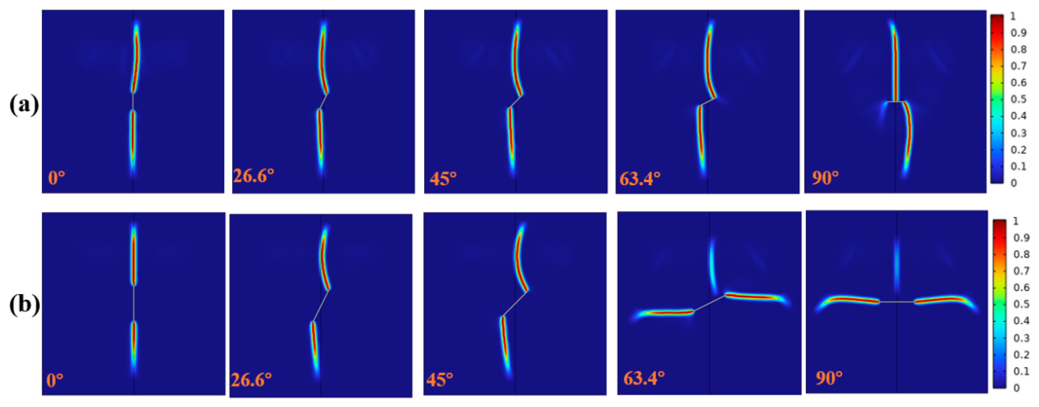
4.1. The Influence of Initial Crack Angle on Crack Propagation

Figure 3 presents the simulation results of ceramic specimens with various pre-existing crack angles (0°, 26.6°, 45°, 63.4°, and 90°) under flame thermal shock. It is clear that the initiation and propagation of initial cracks at five different angles exhibit remarkably similar processes under flame thermal shock. The x-direction stress distribution in the ceramic plate is impacted by the change in the temperature gradient when the upper edge of the ceramic plate experiences flame thermal shock. The ends of the cracks develop into a wing-shaped pattern, and the cracks grow outward along the width direction of the sample. As shown in Figure 3, the simulation results agree well with the experimental results in reference [49]. It is indicated that the proposed phase-field model can simulate the crack patten under hot thermal shock. And it is interesting to remark that there is a difference between the hot thermal shock and the cold shock [47,48]. When the ceramic is subjected to cold shock, the cracks will initiate form the cold surface, and expand inward. However, the cracks tend to propagate from the inside under hot shock. This difference is due to the stress field in the ceramic specimen. It should be noted that the change in the prefabricated crack angle will have some slight implications on the distribution of stress, while the effect on the temperature gradient is insignificant.
The crack propagation process in different periods is explored by taking an initial crack angle of 0° as an example. Figure 4 shows the phase-field evolution stages, the x-direction stress distribution, and the temperature gradient changes of the ceramic plate. During the period of 0–0.21 s, the temperature near the heating surface rises rapidly due to the loading of the upper edge due to the thermal shock of the flame, generating an obvious temperature gradient. As a result, the crack forms, and the stress near the crack tip increases significantly, driving the crack to propagate towards the upper edge. In the period of 0.21–0.34 s, the flame thermal shock load remains loaded on the ceramic plate, causing a larger temperature gradient and a stronger driving force for crack propagation. The crack propagation rate rises dramatically at this stage because of the influence of the temperature gradient. Although the top edge of the ceramic plate is still continuously subjected to flame thermal shock during the period of 0.34–1.0 s, the temperature gradient tends to be stable throughout this period. Therefore, the crack propagation rate exhibits a trend of initially increasing, and then, progressively decreasing.

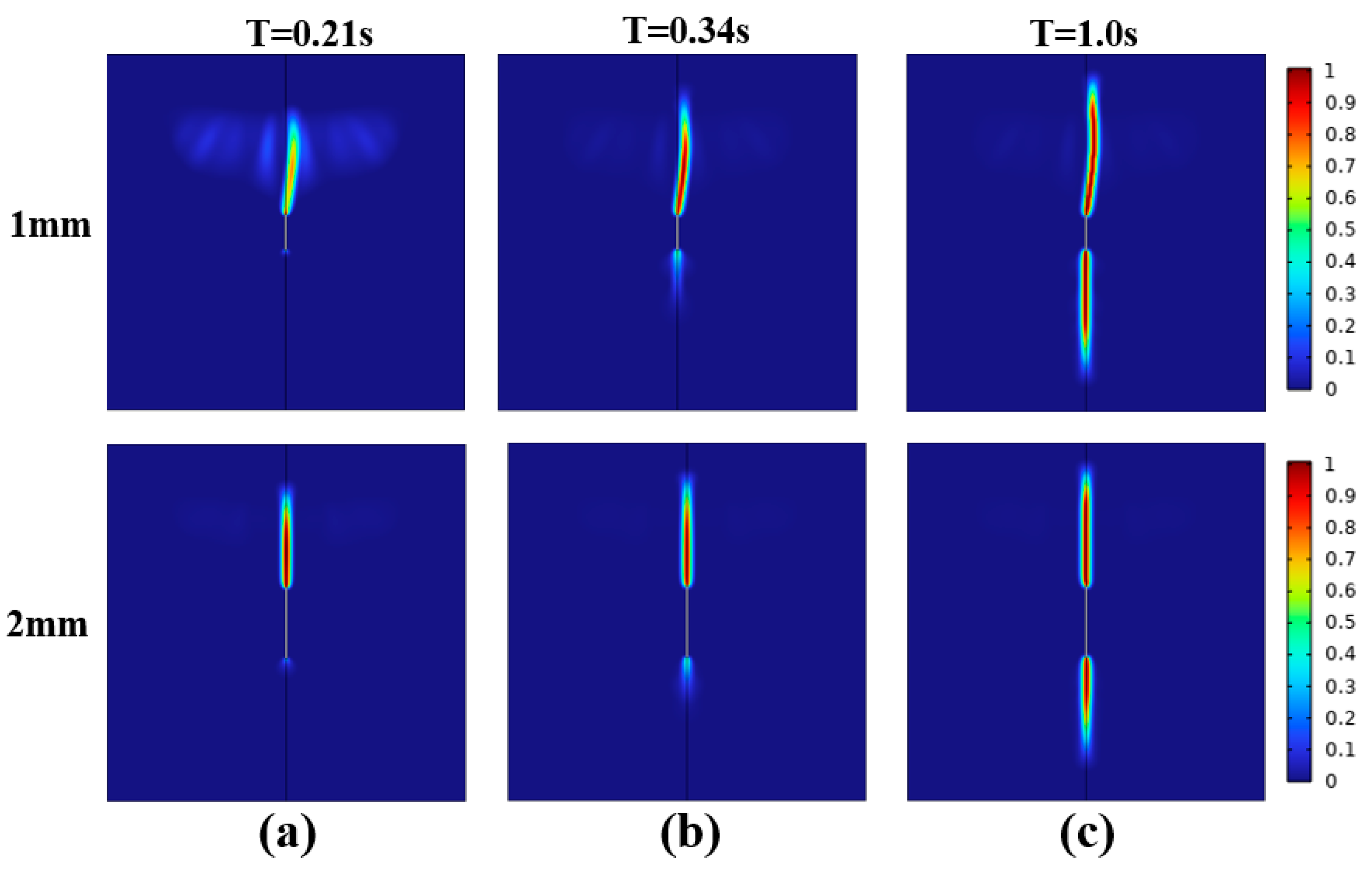
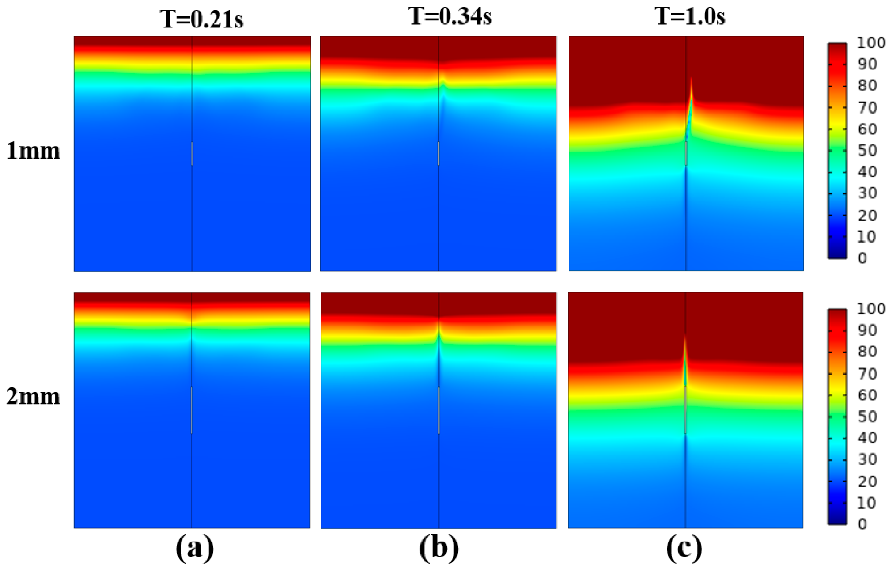
4.2. The Influence of Initial Crack Length on Crack Propagation

The impact of the initial crack length on the crack growth behavior is examined in this section. The crack extension during flame thermal shock loading for a prefabricated crack length of 2 mm is displayed in Figure 5. The graph demonstrates that the trend of crack extension continues to extend along the upper edge of the applied flame thermal shock at prefabricated crack angles of 0°, 26.6°, and 45°, which is the same as that in Section 4.1. However, the crack propagation direction changes when the crack angle is between 63.4° and 90°. In this section, the differences in the crack propagation rate, stress distribution, and temperature gradient caused by variations in the length of pre-existing cracks are explored.
Crack propagation, x-direction stress distribution, and temperature distribution diagrams for two different lengths of pre-existing cracks (1 mm and 2 mm) are displayed in Figure 6a, b and c, respectively, to visually demonstrate the influence of different lengths of pre-existing cracks on crack propagation under flame thermal shock loading.
As exhibited in Figure 6, the crack growth rate rises with the crack length, particularly close to the upper tip of the flame thermal shock load. A temperature gradient develops between the upper edge and the interior of the ceramic under the impact of thermal shock loading. When compared to the crack length of 1 mm, the longer crack length is more prone to being affected by the temperature gradient earlier. Therefore, the extension rate of the upper tip of the crack is greatly increased. However, the temperature gradient within the ceramic tends to stay stable as long as the flame thermal shock load is maintained. The crack propagation rate slows down in the latter two stages, which is consistent with the findings in Section 4.1. Nevertheless, the propagation rate of the lower tip decreases as the length of the prefabricated crack at the lower tip of the crack increases. The temperature gradient change is not obvious because the distance between the lower tip of the crack and the upper surface of the flame thermal shock load rises. It can be concluded from the comparative analysis that the upper crack tip is more likely to initiate a crack than the lower crack tip. Additionally, the maximum growth pace of the upper crack tip increases with the distance from the heated surface. On the contrary, the maximum propagation speed of the lower crack tip decreases with this distance.
The x-direction stress and temperature distribution for different lengths of pre-cracks are illustrated in Figure 7 and Figure 8. The variation in crack length does not cause significant temperature changes, except for slight differences around the crack tip. Overall, the length of the crack has little effect on the temperature distribution. Similarly, the stress distribution seems to be mostly constant over the length of the crack, with only slight differences near the crack tip.

5. Conclusions

The influence of pre-cracked ceramic plates under flame thermal shock is studied in depth in this paper according to the finite element simulation results based on the phase-field thermodynamic coupling model, mainly from the two aspects of pre-cracked angle and length. Therefore, the following specific conclusions are drawn. A relatively obvious temperature gradient is formed rapidly at the upper region of the ceramic plate under flame thermal shock load. This causes the formation of wing-shaped cracks at both ends of the prefabricated crack, which gradually spread in the direction of the thermal shock load. It is found that the tip region of the crack is more susceptible to temperature gradients for ceramic plates with different lengths of prefabricated cracks as the crack length increases, resulting in easier crack initiation and propagation. The simulation of different prefabricated crack lengths reveals that the upper tip of the crack is more likely to generate wing-shaped cracks than the lower tip. The simulation results are in agreement with the experimental results in the reference, and the crack pattern under hot thermal shock is different to that under cold shock. The proposed model can be used to analyze other materials under hot thermal shock.

Author Contributions

Conceptualization, Z.W. and Q.S.; methodology, Z.W.; software, S.Y.Z. All authors have read and agreed to the published version of the manuscript.

Funding

This work was supported by the National Natural Science Foundation of China (Grant No. 12002230) and the Scientific and Technological Innovation Programs of Higher Education Institutions in Shanxi (2021L327).

Data Availability Statement

The data presented in this study are available in this article.

Conflicts of Interest

The authors declare no conflict of interest.

References

  1. Wang, Y.; Zhou, X.; Zhang, T. Size effect of thermal shock crack patterns in ceramics: Insights from a nonlocal numerical approach. Mech. Mater. 2019, 137, 103133. [Google Scholar] [CrossRef]
  2. Fahrenholtz, W.G.; Hilmas, G.E. Ultra-high temperature ceramics: Materials for extreme environments. Scr. Mater. 2017, 129, 94–99. [Google Scholar] [CrossRef]
  3. Monteverde, F.; Savino, R. ZrB2-SiC Sharp Leading Edges in High Enthalpy Supersonic Flows. J. Am. Ceram. Soc. 2012, 95, 2282–2289. [Google Scholar] [CrossRef]
  4. Savino, R.; Mungiguerra, S.; Di Martino, G.D. Testing ultra-high-temperature ceramics for thermal protection and rocket applications. Adv. Appl. Ceram. 2018, 117 (Suppl. S1), s9–s18. [Google Scholar] [CrossRef]
  5. Wei, K.; Liang, D.; Mei, M.; Yang, X.; Chen, L. A viscoelastic model of compression and relaxation behaviors in preforming process for carbon fiber fabrics with binder. Compos. Part. B Eng. 2019, 158, 1–9. [Google Scholar] [CrossRef]
  6. Cao, Y.; Wang, Q.; Ning, X.; Liu, Y. Evaluation of the phase stability, and mechanical and thermal properties of Ba(Sr1/3Ta2/3)O3 as a potential ceramic material for thermal barrier coatings. Ceram. Int. 2019, 45, 12989–12993. [Google Scholar] [CrossRef]
  7. Han, J.-C.; Wang, B.-L. Thermal shock resistance of ceramics with temperature-dependent material properties at elevated temperature. Acta Mater. 2011, 59, 1373–1382. [Google Scholar] [CrossRef]
  8. Wang, A.; Hu, P.; Du, B.; Fang, C.; Zhang, D.; Zhang, X. Cracking behavior of ZrB2-SiC-Graphite sharp leading edges during thermal shock. Ceram. Int. 2018, 44, 7694–7699. [Google Scholar] [CrossRef]
  9. Wang, Y.; Xia, B.; Su, H.; Chen, H.; Feng, X. Improving the thermal shock resistance of ceramics by crack arrest blocks. Sci. China Technol. Sci. 2016, 59, 913–919. [Google Scholar] [CrossRef]
  10. Li, Y.; Li, Q.; Wu, X.; Shao, Y.; Li, L.; Song, F. Cracking in the translucent alumina ceramic during flame thermal shock. Ceram. Int. 2021, 47, 30974–30979. [Google Scholar] [CrossRef]
  11. Su, X.; Liu, G.; Dai, B.; Hu, B.; Fu, S.; Wan, D.; Bao, Y.; Feng, Q.; Grasso, S.; Hu, C. Ablation mechanisms of Ti3SiC2 ceramic at 1600 °C in nitrogen plasma flame. Ceram. Int. 2022, 48, 14004–14013. [Google Scholar] [CrossRef]
  12. Liu, C.; Cai, C.; Xie, J.; Guo, W.; Qin, H.; Gao, P.; Xiao, H. Effect of surface brittle-to-ductile transition on high-temperature thermal shock resistance of Al2O3 ceramics. Ceram. Int. 2022, 48, 20627–20638. [Google Scholar] [CrossRef]
  13. Tang, S.B.; Zhang, H.; Tang, C.A.; Liu, H.Y. Numerical model for the cracking behavior of heterogeneous brittle solids subjected to thermal shock. Int. J. Solids Struct. 2016, 80, 520–531. [Google Scholar] [CrossRef]
  14. Bourdin, B.; Marigo, J.-J.; Maurini, C.; Sicsic, P. Morphogenesis and Propagation of Complex Cracks Induced by Thermal Shocks. Phys. Rev. Lett. 2014, 112, 014301. [Google Scholar] [CrossRef] [PubMed]
  15. Wang, Y.; Zhou, X.; Kou, M. An improved coupled thermo-mechanic bond-based peridynamic model for cracking behaviors in brittle solids subjected to thermal shocks. Eur. J. Mech.-A/Solids 2019, 73, 282–305. [Google Scholar] [CrossRef]
  16. Chu, D.; Li, X.; Liu, Z. Study the dynamic crack path in brittle material under thermal shock loading by phase field modeling. Int. J. Fract. 2017, 208, 115–130. [Google Scholar] [CrossRef]
  17. Li, J.; Song, F.; Jiang, C. Direct numerical simulations on crack formation in ceramic materials under thermal shock by using a non-local fracture model. J. Eur. Ceram. Soc. 2013, 33, 2677–2687. [Google Scholar] [CrossRef]
  18. Jiang, W.; Spencer, B.W.; Dolbow, J.E. Ceramic nuclear fuel fracture modeling with the extended finite element method. Eng. Fract. Mech. 2020, 223, 106713. [Google Scholar] [CrossRef]
  19. Menouillard, T.; Belytschko, T. Analysis and computations of oscillating crack propagation in a heated strip. Int. J. Fract. 2011, 167, 57–70. [Google Scholar] [CrossRef]
  20. Meng, J.; Cao, P.; Huang, J.; Lin, H.; Chen, Y.; Cao, R. Second-order cone programming formulation of discontinuous deformation analysis. Int. J. Numer. Methods Eng. 2019, 118, 243–257. [Google Scholar] [CrossRef]
  21. Giannakeas, I.N.; Papathanasiou, T.K.; Bahai, H. Simulation of thermal shock cracking in ceramics using bond-based peridynamics and FEM. J. Eur. Ceram. Soc. 2018, 38, 3037–3048. [Google Scholar] [CrossRef]
  22. Cao, C.; Zhao, Y.; Dai, D.; Zhang, X.; Song, Z.; Liu, Q.; Liu, G.; Gao, Y.; Zhang, H.; Zheng, Z. Simulation analysis and optimization of laser preheating SiC ceramics based on RSM. Int. J. Therm. Sci. 2023, 185, 108070. [Google Scholar] [CrossRef]
  23. Dong, X.; Shin, Y.C. Crack formation within ceramics via coupled multiscale genome and XFEM predictions under various loading conditions. Eng. Fract. Mech. 2018, 204, 517–530. [Google Scholar] [CrossRef]
  24. Francfort, G.A.; Marigo, J.-J. Revisiting brittle fracture as an energy minimization problem. J. Mech. Phys. Solids 1998, 46, 1319–1342. [Google Scholar] [CrossRef]
  25. Bourdin, B.; Francfort, G.A.; Marigo, J.-J. Numerical experiments in revisited brittle fracture. J. Mech. Phys. Solids 2000, 48, 797–826. [Google Scholar] [CrossRef]
  26. Miehe, C.; Welschinger, F.; Hofacker, M. Thermodynamically consistent phase-field models of fracture: Variational principles and multi-field FE implementations. Int. J. Numer. Methods Eng. 2010, 83, 1273–1311. [Google Scholar] [CrossRef]
  27. Miehe, C.; Hofacker, M.; Welschinger, F. A phase field model for rate-independent crack propagation: Robust algorithmic implementation based on operator splits. Comput. Methods Appl. Mech. Eng. 2010, 199, 2765–2778. [Google Scholar] [CrossRef]
  28. Miehe, C.; Welschinger, F.; Hofacker, M. A phase field model of electromechanical fracture. J. Mech. Phys. Solids 2010, 58, 1716–1740. [Google Scholar] [CrossRef]
  29. Wu, J.-Y.; Nguyen, V.P. A length scale insensitive phase-field damage model for brittle fracture. J. Mech. Phys. Solids 2018, 119, 20–42. [Google Scholar] [CrossRef]
  30. Wu, J.-Y. A geometrically regularized gradient-damage model with energetic equivalence. Comput. Methods Appl. Mech. Eng. 2018, 328, 612–637. [Google Scholar] [CrossRef]
  31. Yu, Y.; Hou, C.; Zhao, M. Phase field model for brittle fracture using threshold strategy. Theor. Appl. Fract. Mech. 2023, 125, 103831. [Google Scholar] [CrossRef]
  32. Xing, C.; Yu, T.; Sun, Y.; Wang, Y. An adaptive phase-field model with variable-node elements for fracture of hyperelastic materials at large deformations. Eng. Fract. Mech. 2023, 281, 109115. [Google Scholar] [CrossRef]
  33. Zheng, S.; Huang, R.; Lin, R.; Liu, Z. A phase field solution for modelling hyperelastic material and hydrogel fracture in ABAQUS. Eng. Fract. Mech. 2022, 276, 108894. [Google Scholar] [CrossRef]
  34. Zhou, S.; Zhuang, X.; Rabczuk, T. A phase-field modeling approach of fracture propagation in poroelastic media. Eng. Geol. 2018, 240, 189–203. [Google Scholar] [CrossRef]
  35. Ruan, H.; Rezaei, S.; Yang, Y.; Gross, D.; Xu, B.-X. A thermo-mechanical phase-field fracture model: Application to hot cracking simulations in additive manufacturing. J. Mech. Phys. Solids 2023, 172, 105169. [Google Scholar] [CrossRef]
  36. Miehe, C.; Sch¨anzel, L.-M.; Ulmer, H. Phase field modeling of fracture in multi-physics problems. Part I. Balance of crack surface and failure criteria for brittle crack propagation in thermo-elastic solids. Comput. Methods Appl. Mech. Eng. 2015, 294, 449–485. [Google Scholar] [CrossRef]
  37. Li, D.; Li, P.; Li, W.; Li, W.; Zhou, K. Three-dimensional phase-field modeling of temperature-dependent thermal shock-induced fracture in ceramic materials. Eng. Fract. Mech. 2022, 268, 108444. [Google Scholar] [CrossRef]
  38. Mandal, T.K.; Nguyen, V.P.; Wu, J.-Y.; Nguyen-Thanh, C.; de Vaucorbeil, A. Fracture of thermo-elastic solids: Phase-field modeling and new results with an efficient monolithic solver. Comput. Methods Appl. Mech. Eng. 2021, 376, 113648. [Google Scholar] [CrossRef]
  39. Biot, M.A. General Theory of Three-Dimensional Consolidation. J. Appl. Phys. 1941, 12, 155–164. [Google Scholar] [CrossRef]
  40. Schrefler, B.A.; Gawin, D. The Effective Stress Principle: Incremental or Finite Form? Int. J. Numer. Anal. Methods Geomech. 1996, 20, 785–814. [Google Scholar] [CrossRef]
  41. Coleman, B.D.; Noll, W. The thermodynamics of elastic materials with heat conduction and viscosity. In The Foundations of Mechanics and Thermodynamics; Springer: Berlin/Heidelberg, Germany, 1974; pp. 145–156. [Google Scholar]
  42. Wu, J.-Y.; Mandal, T.K.; Nguyen, V.P. A phase-field regularized cohesive zone model for hydrogen assisted cracking. Comput. Methods Appl. Mech. Eng. 2020, 358, 112614. [Google Scholar] [CrossRef]
  43. Kitamura, K. Crack Surface Energy: Temperature and Force Dependence. Mater. Trans. 2008, 49, 643–649. [Google Scholar] [CrossRef]
  44. Bayoumi, M.R.; Bassim, M.N. Temperature dependence of fracture toughness J IC and ductility for BCC materials in the transition region. Int. J. Fract. 1983, 23, 259–269. [Google Scholar] [CrossRef]
  45. Wu, J.-Y.; Chen, W.-X. On the phase-field modeling of fully coupled chemo-mechanical deterioration and fracture in calcium leached cementitious solids. Int. J. Solids Struct. 2022, 238, 111380. [Google Scholar] [CrossRef]
  46. Stumpf, H.; Hackl, K. Micromechanical concept for the analysis of damage evolution in thermo-viscoelastic and quasi-brittle materials. Int. J. Solids Struct. 2003, 40, 1567–1584. [Google Scholar] [CrossRef]
  47. Chen, W.-X.; Wu, J.-Y. Phase-field cohesive zone modeling of multi-physical fracture in solids and the open-source implementation in Comsol Multiphysics. Theor. Appl. Fract. Mech. 2022, 117, 103153. [Google Scholar] [CrossRef]
  48. Zhuang, X.; Zhou, S.; Huynh, G.; Areias, P.; Rabczuk, T. Phase field modeling and computer implementation: A review. Eng. Fract. Mech. 2022, 262, 108234. [Google Scholar] [CrossRef]
  49. Li, Q.; Li, Y.; Li, J.; Li, L.; Wu, X.; Shao, Y.; Charles, Y.; Barboura, S.; Song, F. Prefabricated crack propagation in translucent alumina ceramic sheets during flame thermal shock. Eng. Fract. Mech. 2022, 263, 108285. [Google Scholar] [CrossRef]
Figure 1. A cracking solid with cracks.
Applsci 13 12633 g001
Figure 2. (a) Geometry model and boundary conditions of ceramic plate, (b) finite element mesh.
Applsci 13 12633 g002
Figure 3. Evolution of thermal shock cracks in prefabricated cracked ceramic plates from five angles. (a) Damage; (b) x-direction stress distribution (MPa); (c) temperature distribution (°C); and (d) the results of reference [49].
Applsci 13 12633 g003
Figure 4. The initial crack angle of 0°: (a1a3) phase-field evolution; (b1b3) x-direction stress (MPa); (c1c3) temperature distribution (°C).
Applsci 13 12633 g004
Figure 5. Crack propagation diagram under the influence of different prefabricated crack lengths: (a) 1 mm; (b) 2 mm.
Applsci 13 12633 g005
Figure 6. Crack propagation diagram for different prefabricated crack lengths at different time: (a) 0.21 s, (b) 0.34 s and (c) 1 s.
Applsci 13 12633 g006
Figure 7. x-direction stress diagram for different prefabricated crack lengths at different time: (a) 0.21 s, (b) 0.34 s and (c) 1 s.
Applsci 13 12633 g007
Figure 8. Temperature distribution diagram for different prefabricated crack lengths at different time: (a) 0.21 s, (b) 0.34 s and (c) 1 s.
Applsci 13 12633 g008
Table 1. Material parameters [49].
E υ f t G f T 0 q 0
370   G P a 0.22 30   M P a 22.47   N / m 20   ° C 2,000,000 ( W / m 2 )
Disclaimer/Publisher’s Note: The statements, opinions and data contained in all publications are solely those of the individual author(s) and contributor(s) and not of MDPI and/or the editor(s). MDPI and/or the editor(s) disclaim responsibility for any injury to people or property resulting from any ideas, methods, instructions or products referred to in the content.

